

Page 1

Up-turned edge
Alignment mark
Alignment Point
Alignment
Point
Locking Ta b
Down-turned Edge
Pre-Punched
fastening holes
Locking Ta b
Connecting Area
15-3/4”
Expanded
Polystyrene
Backer Board
Installation Guide
Valley @
Dormer Area
Eave Line
8-3/8”
22-1/4”
Strike square horizontal chalk line
at shingle course as a “benchmark”
to work at opposite side of valley.
Horizontal chalk line
for first course
CastleTop is a diamond shaped at metal shingle. These shingles have a unique
locking feature that allow for easy installation. The overlapping shingles have a
turned down edge on the lower front and a turned up edge on the upper front.
The panel is 15 ¾” square, net coverage is 13 ⁄” x 13 ⁄”. There are approximately
78 shingles per 100 square feet. The CastleTop shingle is packed 39 shingles
per carton, which equates to approximately half of a square.
Review and understand
complete guide before
beginning installation.
This guide has been prepared
as suggested details to
particular design conditions.
Each condition has cer tain
limitations to per formance, aesthetics
or economics. Professionals qualified to assess the
information regarding suitability for a specific project
should determine that the selection and installation
are made to their requirements. ATAS cannot assume
any responsibility for the actual selection and/or
installation of materials. The panels, flashings and trim
shown in this guide, illustrated over solid and plumb
substrate, assume that the structure has been
designed and prepared in accordance with local
building codes.
Published panel width dimensions are to be considered as nominal dimensions. Overall panel
width dimensions may vary during installation due to adjustments to accommodate as built roof
conditions.
Shingle Layout
It is recommended to apply
waterproof membrane, such as
ATA-Shield**, at eave, gable, and
valley. Place ATA-Guard*
underlayment up from the eave.
For re-roof applications, remove
the extended roof material and old
drip edge. After Starter Trim is
installed (see page 2), snap a
horizontal chalk line at 8 ⁄” from
the edge after squaring up eave.
Snap vertical lines at 11 ⁄” o.c.
Line-up shingle corners with chalk
lines to assure square alignment of
the shingles. To aid in squaring of
shingle, make sure alignment
points meet at the alignment mark
of the lower course. Shingles are
secured with three fasteners per
shingle.
Helpful hint: to square-up the
shingle, line up the top hole with the
vertical line.
Page 2
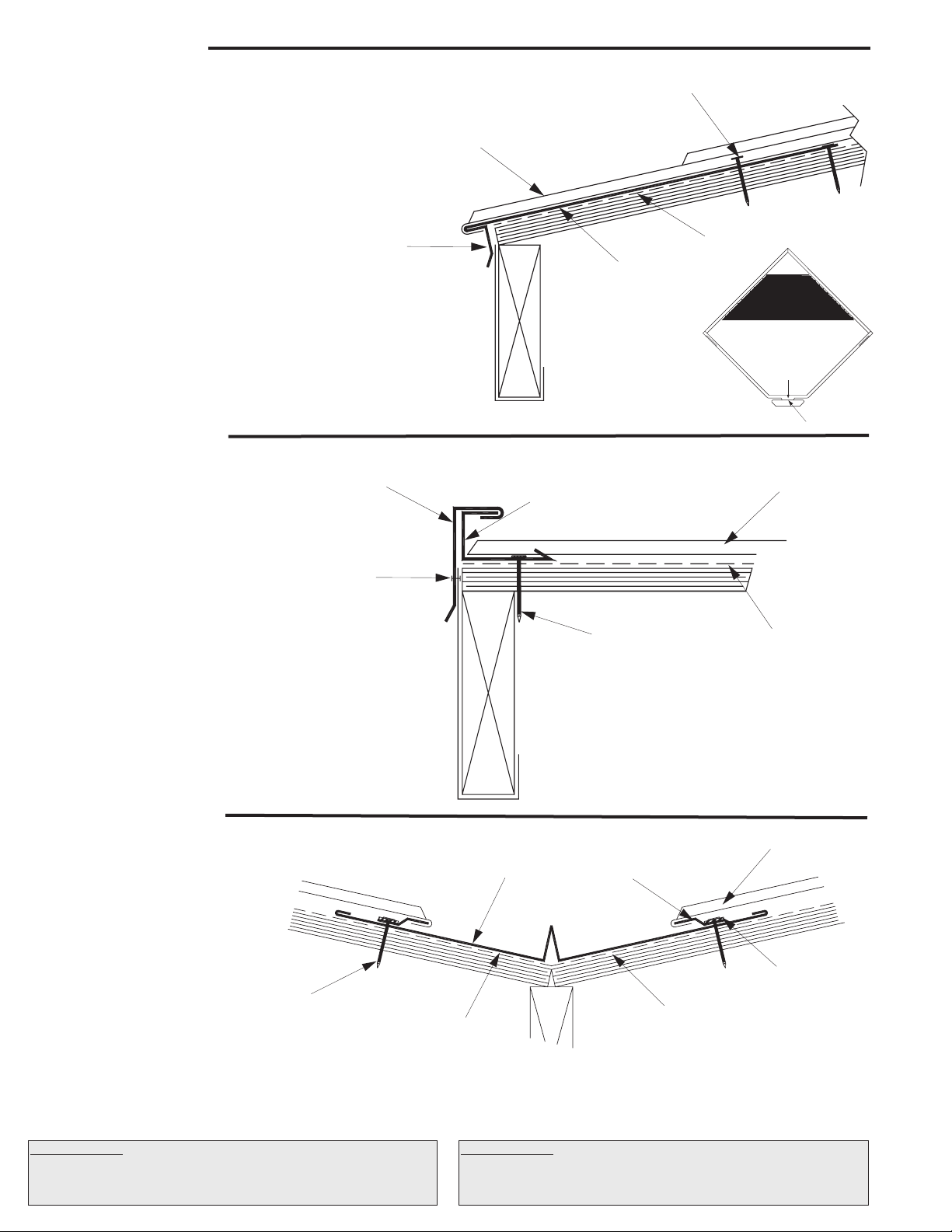
Eave Detail
ATA-Guard*
Castle Top Shingle
2” Ring Shank
Grommetted Nail
HCA112
Drip Edge/
Starter Trim
ATA-Shield**
ATA-Guard*
Castle Top Shingle
2” Ring Shank
Grommetted Nail
Approriate
Fastener
HCA201
Gable Trim Cap
HCA200 Channel Trim
Butyl Ta pe
ATA -Guard*
Castle Top Shingle
2” Ring Shank
Grommetted Nail
HCA800
Valley Pan
HCA975
Joggle Cleat
ATA -Shield**
Remove foam backer from
lower part of shingle
first row only
Bend Line
Cut Line
1. When applying in a re-roof application, cut back
existing shingles and drip edge to be flush with the
eave and gable lines. Apply ATA-Shield at eave.
2. Install Drip Edge/Starter Trim. Place lap joint of
starter trim at center of shingles to hide seam.
Fasteners should be located under the center of each
shingle.
3. Apply ATA-Guard to entire roof.
4. Remove the foam backer from lower half of the first
row of shingles to assure a flat seal onto the starter
trim.
5. Cut lower part of locking edge from shingle (see
detail); bend the remaining tab inward under edge of
starter trim to avoid wind uplift. Fasteners must
penetrate solid substrate.
Gable Detail
1. Install Channel Trim on gable edge, fasten into
the substrate 12” o.c.
2. Insert cut edge of shingles into channel trim.
3. Hook Gable trim over channel, fasten with
appropriate fastners.
Valley Detail
1. Install ATA-Shield** 18” up both side of
the valley line.
2. Install the valley with the joggle cleat
maintaining a 3” clearance from valley’s
center. Place butyl tape between joggle
cleat and pan. Fasten through tape into
the substrate 6” o.c. max.
3. Overlap valley pans by a minimum of
6”.Apply butyl tape/caulk between all
valley metals.
4. Cut backer foam 1” from cut edge of
shingle and turn shingle under as shown.
5. Hook shingles onto the joggle cleat and lay in the valley pan and fasten.
Maintain square line-up of shingles.
Underlayments: ATA-Guard* is a polyolefin based, 100% asphalt free,
high strength reinforced roofing underlayment for use beneath
metal roofing on steep slope applications. 1000 sq. ft. per roll at 48”
wide.
Underlayments: ATA-Shield** is the recommended self adhesive
underlayment for eaves, sidewall and any critical areas exposed to ice
damming and extensive water run off. Available in 65’-8” x 39 ⁄” rolls
(200 sq. ft. per roll).
Page 3
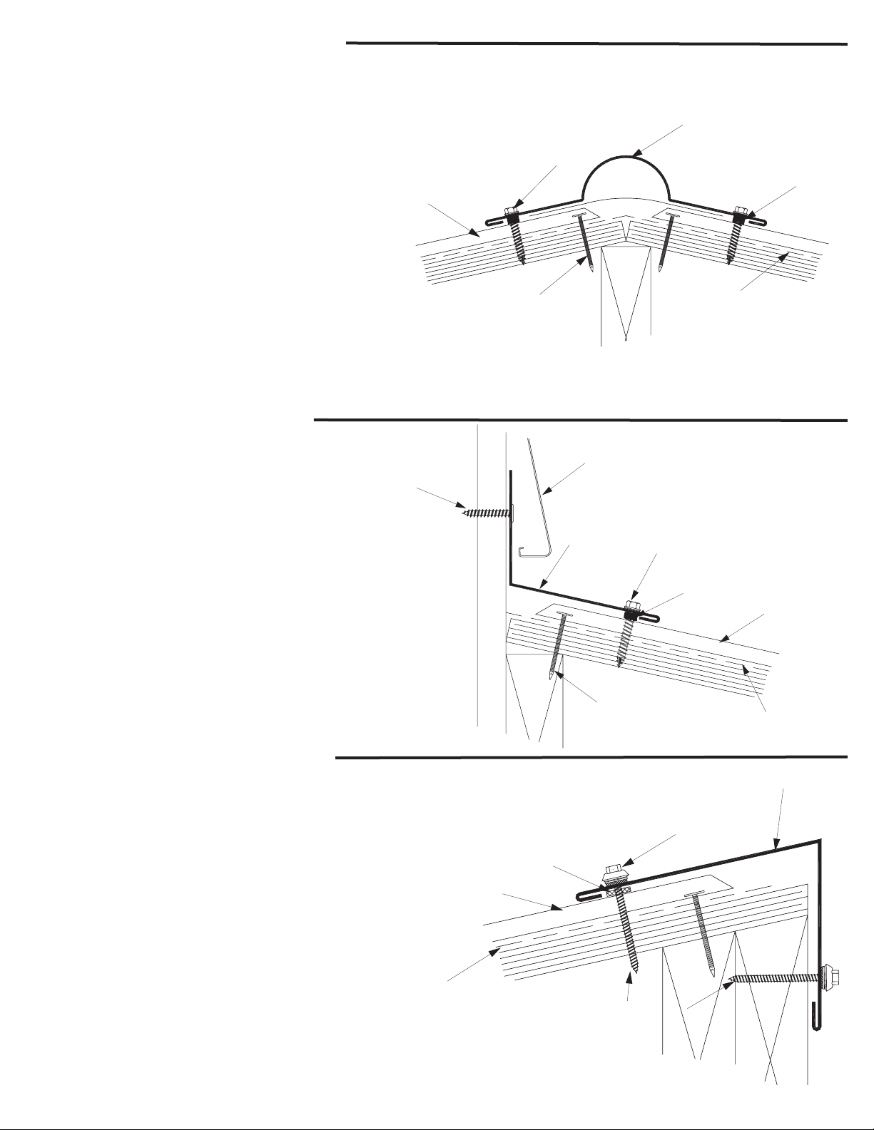
Hip & Ridge Detail
ATA -Guard*
Castle Top Shingle
2” Ring Shank
Grommetted Nail
2” x 5/16” Painted
Gasketed Screw
HCA303
Ridge/Hip Cap
Soft Cell Closure Ta pe
ATA -Guard*
Castle Top Shingle
2” Ring Shank
Grommetted Nail
2” x 5/16” Painted
Gasketed Screw
HCA500
Headwall
Tr im
Approriate
Fastener
Soft Cell Closure Ta pe
Wall Tr eatment
ATA -Guard*
Castle Top Shingle
2” Ring Shank
Grommetted Nail
HCA342
Shed Ridge
Cap
Soft Cell
Closure Ta pe
2” x 5/16” Painted
Gasketed Screw
Hip and ridge applications are handled
in the same manner.
1. Install Castle Top roof shingles to meet at hip/ridge.
2. Apply expandable sealant tape to ridge cap; place
just behind returned edge of cap.
3. Secure the cap with 2” x ⁄” painted gasketed
screws on each side of ridge at approximately 2’-0” o.c.
Make sure the screw penetrates soft cell closure
between metals.
Note: Make sure to fasten the caps to the high point on
the shingle in order to avoid dimpling, and make sure the
screw penetrates the cap through the expandable
sealant tape into the solid substrate. Ridge caps can
accommodate standard ridge venting products. Refer to
venting manufacturer’s instructions and local building
code requirements.
Headwall Detail
1. Install the shingles up to the headwall.
2. Depending on wall treatment, cut reglet in wall.
3. Apply soft cell closure tape to the headwall trim just
behind returned hem of headwall.
4. Lay headwall trim over shingles while insuring that the
perpendicular section is flush to the wall.
5. Secure the headwall with 2” x ⁄” painted gasketed
screws at approximately 2’-0” o.c. Make sure the screw
penetrates soft cell closure between metals.
6. Install counterflashing or wall treatment over headwall.
Shed Ridge Detail
1. Install metal shingle up to the roof peak.
2. Apply soft cell closure tape on the inside of the shed ridge
cap just above the hem.
3. Lay shed ridge trim over shingles while insuring that the
cap is tight against the peak.
4. Secure shed ridge cap with 2” x ⁄” painted gasketed
screws at 24” o.c., making sure to fasten through tape and
shingle into solid substrate.
Page 4

Sidewall Detail
Approriate
Fastener
Wall Treatment
HCA410
Sidewall Trim
HCA200
Channel Trim
Castle Top
Shingle
Blocking
ATA -Guard*
Trim Boards
Wood Substrate
1” Screw (Shown)
or 2” Screw Shank
Grommetted Nail
1. Install ATA-Shield** along roof plane and up
sidewall.
2. Install channel trim; fasten into the substrate 12”
o.c.
3. Place panel into channel, fasten.
4. Apply soft cell closure tape in channel.
5. Install sidewall trim. Secure to the exterior wall.
6. Install wall treatment or counterflashing.
Note Regarding Trim Details
The application of flashing and trim requires a detailed approach. Consideration should be given to the roof ’s geometry and course it creates for
water run-off. Location of gutters and the use of snow retention systems should also be considered. Proper planning regarding the sequence of
material overlap is critical. Sealants, such as butyl tapes and tripolymers, should be used at overlapping trim edges, in conjunction with exposed
fasteners, and to seal flashings. All fasteners should be properly tightened and not overdriven at an angle. Fasteners that are too loose can “back out”
over time. An overdriven fastener may cause a depression in the material, which becomes a collection point for standing water.
Pipe Detail
Step 1
Cut on the proper pipe
diameter marked on the
flashing.
Pipe drawings provided by Triangle Fasteners
Tools and Rules:
Basic Equipment Required:
Tie-off ropes, safety harness, long level, ladders, scaffolding with
approved planking, extension cords with approved ground plugs
and services.
Additional Tools:
Metal folding tool, hammer, chalk line, measuring tape, metal
cutting tools - nibblers, drills, hacksaw, utility knife, pop-rivet
gun, caulking guns, layout and combination square, C clamps,
sheet metal shears (including RH, LH, straight and overhand).
Power driven screw gun with proper bits, depth-setting
nosepiece, variable speed.
Choose the correct equipment and tools to do the job in a
safe manner. Wear safety gear and follow OHSA
requirements.
Position over pipe and slide
For further information or assistance, contact our Product Support at 800.468.1441
Step 2
down the pipe.
Corporate Office - Allentown, PA 18106 www.atas.com (610.395.8445)
©2012 ATAS International, Inc. and Accel Roofing Products. All rights reserved. CastleTop® is a registered trademark of ATAS International, Inc.
Apply polyurethane sealant
to the bottom of the base.
1. Never cut the panels with an abrasive cut-off wheel or torch, as this will damage
the finish.
2. Do not weld the trim or panels.
3. Remove any small burrs left by cutting, screwing or drilling.
4. Remove protective masking immediately after trim and panels are installed.
5. Caution should be taken when unloading the panels to prevent damage.
6. Use appropriate screws for the type of underlayment and long enough to fully
penetrate and secure the panel.
7. The stored materials should be kept dry.
8. Do not cut on finished roof. Remove all drill spirals, chips and dust immediately.
9. Seal neoprene closures and soft cell foam by applying appropriate sealant to
both surfaces.
10. Put appropriate sealant/butyl tape between overlapping trims.
11. Overlap trims in a manner not to impede the flow of water.
Step 3
Mold the flexible base to the
Follow these simple rules:
Step 4
panel contours.
Step 5
Fasten with ¼” x
1 ⁄” drilling
fastener every 1½”
around the base.
ATAS International, Inc.
LRD0412 LAT230
 Loading...