

Page 1

\
I
r
I
I
r
I
•
I
)I~
ATARf
GAM
E S
TM·318
I"~
•
Page 2
Page 3
Corrections/
Tetl·is*
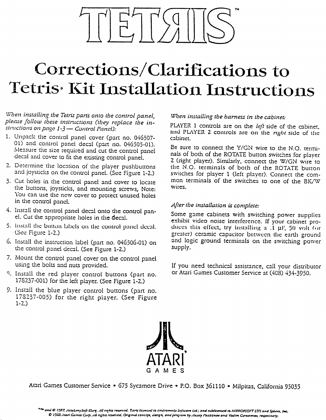
\\i7Jen
installing the Tetris parts onto the
please
s/ntctiollS
1.
.,
3.
follow
Unpack
01)
and
!\'ie::!sure
dec:J.I
Determine
and
joysticks
Cut
holes
the
buttons,
You
c:m
in
the
4. Install
el.
Cut
5.
11lSl:dl
(Set.:
6. Inst:J.ll
the
control
Mount
7.
using
S. Ins(::tll
178237-001)
9.
Install
173237-005)
1-2.)
these instruc/ions (they replace the
012
page
the
control
comrol
the
size
and
cover
the
on
in
(he
joysticks,
use
the
control
the
the
lhe
Figure
the
the
the
pando
comrol
:J.ppropriatc
LHIllLlll
1-2.)
instruction
panel
control
bolts
(he
red
for
the
blue
IUt
1-3
- COl/troL Pane/):
pancl
panel
required
to fit
loc:ttion
tile
control
control
new
panel
I:lbds
decal.
panel
and
nuts
player
the
left
player
for
the
dec:J.I
the
existing
of
panel
and
cover
deal
holes
Ull
bbel
(See
cover
provided.
control
player.
control
right
cover
and
[he
paneL
mounting
to
tht:
(part
Clarifications
Il1stallatioll
(part:
(p:J.rt:
cut
control
player
and
protect
onto
in
the
t:ul1lrul
no.
Figure
on
buttons
(See
player.
control
no.
the
(See
cover
the
decal.
046506-01)
1-2.)
the
Figure
burtons
panel,
no.
046507-
046505-01).
control
pushbu[(ons
screws,
unused
control
(See
panel.
Figure
to loc:lte
control
p:l1ld
(part
1-2.)
(part
panel
1-2.)
Note:
holes
1.1I.:c.::11.
p:mel
Figure
in-
pan-
on
no.
no.
When installing the
PLWER 1 controls
PLAYER
:lIlU
cabinet.
Be
sure
nals
of
2
(right
the
N.O.
switches
mon
wires.
~fter
Some
exhibit
UlIl:c.::;
gre:Hl.!r)
and
supply.
If
you
or
AWri
9
111St1
to
connect
both
of
player).
terminals
for
terminais
harness
are
2
controls
the
the
ROTATE
Similarly,
of
player 1 (left
of
the
uctiOl1.S
in
the cabinet:
on
the
;'Irc
on
Y/GN
button
connect
both
of
player).
switches
(be installalion is complete:
gJ.me
logic
video
this
ceramic
ground
need
Games
c:lbinets
noise
cefc.:t:t,
capac.:itor
technic:ll
Customer
with
switching
interference.
try
Ill:ilalliJlg a
between
terminals
assistance,
Service
on
to
left
side
thc
right
wire
to
switches
the
the
ROTATE
Connect
to
one
If
your
.1
tht!
the
switching
call
:It
(408) 434-3950.
of
the
sidc
me
N.O.
W/GN
of
power
c::Ibinet
~F.
50
earth
your
Clbiner,
of
tile
termi-
for
player
wire
bu[[on
the
com-
the
BK.I\V
supplies
pro-
volt
(or
ground
power
distributor
to
Atari
Games
....
anti 0 19.'7.
o
t%$
Customer
,ICIIII..-,.S<t{I.C1"ry;:.
,11drl CoI,.,er
C4Jrp.
Service
,11/
"Sil"
AU
n.sbu
• 675
,",,"nI.
rc:unni.
Sycamore
T.1rV
/Ic,,",n./ /0
On&,naJ
CD"'cpI.
)I~
ATARf
GAM
tim!"-
Drive
,I
"tiro
",
E S
.......
..
I
pmsram
• P.O.
",
s.V,
..
Box
..,,.../Jd.,
t1y
,I/o:..Lry PazbU"""
361110
If"d
tvblkrou.rd,o
• Milpitas, California
"n"
,IIfRRORJOFT
V""'m
C .......
Lm
"'~
"nd
nsp«1Iurl}'.
Spb<:rr.
95035
Pc.
Page 4
}Ll[l§.
t~tlli11gtll.e
j'oy·s
ticl\:.s
YO"lil·
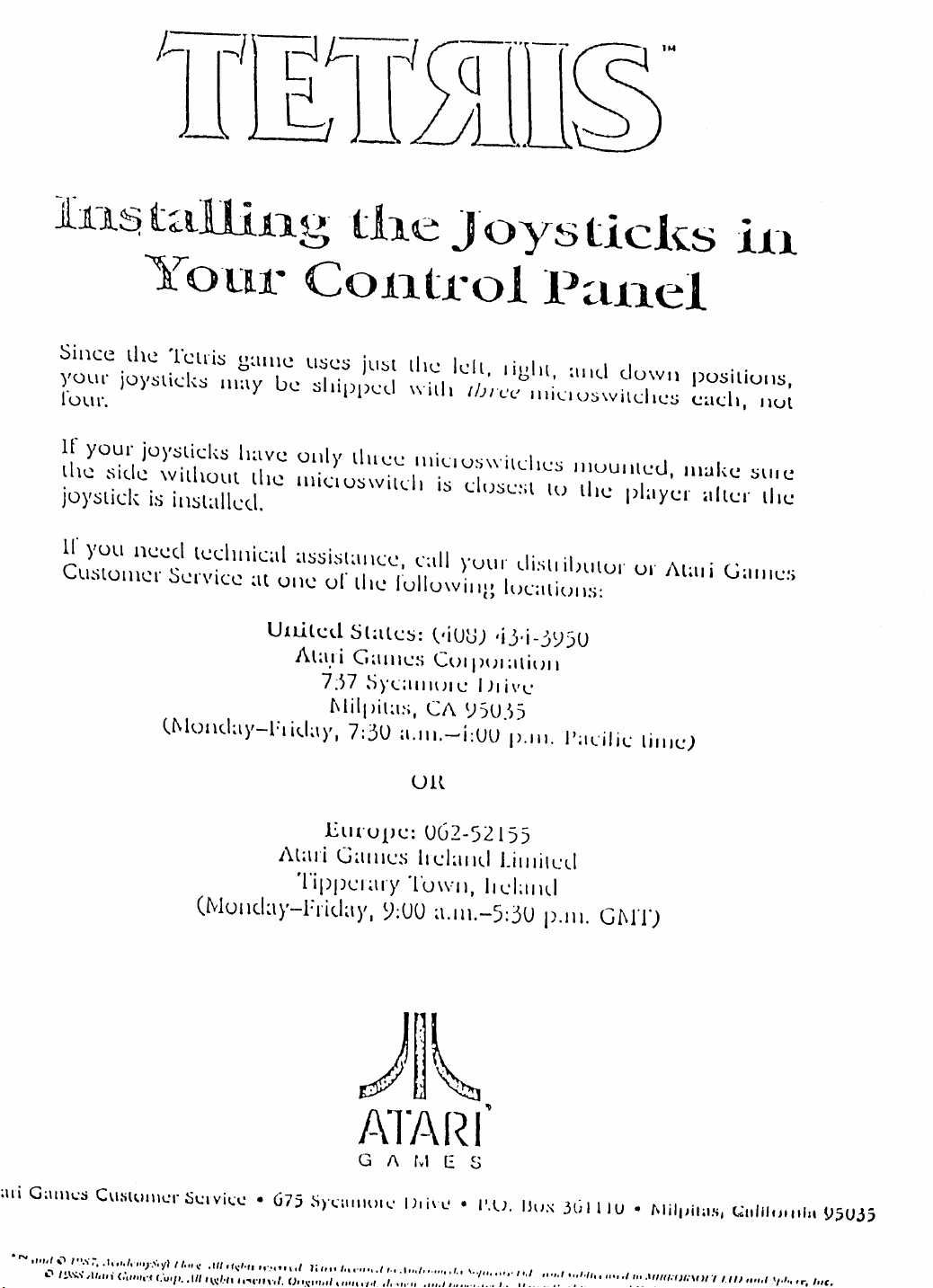
Since
Yol.lr
rOll
If
the
joystick
11'
Cu,stol11cr SI..!l'vicc
joyslicks
r.
your
.sid\..!
YOll
the
Telri~
lllay
joyslicks
without
is
installed.
nCl..!d
ll..!chl1ical
U',lo1Idar-Flida),.
galll\"!
U\..!
have
the
at
ulle
United
C011.tl1toll~~lll.el
lIses
shipped
ollly
IlliclO~wilcll
~\SSisl~1I
ur
Ala,li
757
c\lilpil~I:;,
just
the
wilh
three
llle
11IiClUS\\"ilChes
\CC,
cdl
("ullow
Slales:
GalllCS
SYCIIIH)(C
7:30
a.lIl.-i:uu
Ult
is
~'iUG)
COl
C/\
Id
l.
ffJn:C!
close:;l
yuur
illg
,i)·i-':'Sl5U
PUI
IJliv\...'
t;SU.'»
I
igill.
alld
IlIiuoswilche!';
IlIuullleu,
lu
tile
disll
ilnllor
luClliulls:
;lliull
1',111.
I';lcilic
dowl1
player
ur
i\tal
lilllc..;)
POSitiOIlS,
c..;ach,
Ilwke
.t1tc..;r
stile
i
(J;lIl1e:,
Ilul
lile
;ni
......
G;IlI\l':S
IIIIII
"
I
'.\"i;-,
,-'
l!,.\.')..'\
~lll"i
CUM~lI"l:r
.1,'
•••
1.
"'}'S'
(.',''",,.«
i\lari
(Mullc.la),-hida)'.
Sl!1
vil.:l!
•
675
yl
I
t."
~
.111,
ft.:.""
,,',"
f:Ut/',
.111
,\~/.'t1
9,
"~t'li
\"fl,
Eurupe:
Galllc~
TippCI;\I)'
G
~)'I.:\lI"U'\.·
\.1
1;"
It
In
'.\;1'1,"
,ft'"
""""
'1"
(J,
TUWII,
y;uu
1\
1)1
I.,
.,
...
. •
lId;lIld
tv!
/.
002-52155
Lilllilcd
IlcLllld
a.II\.-5:3U
E S
in!
•
I',U,
""',
,t"
''''/10
"'"
,
Ilux
1,/
p.ll!.
3ti
,.
-I,
f •
,,'·/h
G£\l'n
III
U
I
.",
.111'
•
I\lilpil;lS,
.Hua;OI,'\I
t~lIlj"jlllill
U"
'_III
"".1
\/.1
~~UJj
••
'r,
Page 5

)~
ATARf
GAM
E S
Kit Installation Instructions
no
and
© 1987, AcademySoft-Elorg.
ware
Ltd.;
and
© 1988 Alari Games Corp. All rights reserved, Original concept, design, and program by
Alexey Pazhitnov and Vadirn Gerasimov, respectively.
sublicensed
to
MIRRORSOfT
All
rights reserved. Tetris licensed
LTD
and
Sphere, Inc.
to
Andromeda Soft-
Page 6
Tetris
Copyright © 1989
Corporation.
No
part
of
this publication may be reproduced by any
chanical, photographic or electronic process, or
of
a phonographic recording, nor may
trieval system, transmitted, or othetwise copied for public or
private use, without permission from the publisher.
all
The game play,
al
are protected by the
This
Act
provides for substantial penalties for violating feder-
al copyright laws. Courts can impound infringing articles
while legal action
courts can order destruction
In
addition, the
ages of
cases. Infringers may also have to pay costs and attorneys'
fees and
fines of
$500,000
Atari
rights against infringers.
diately halt any manufacture, distribution, or operation
copy of video games made by us. Anyone who purchases
such copies risks forfeiting such a game.
Published
Atari
675
P.O.
Milpitas, California
Printed
Produced by the
Department.
Editing and Design: Andrea Dencker
Illustration:
up
face
up
in the case of corporations.
Games Corporation
by:
Games Corporation
Sycamore Drive
Box
361110
in
the
graphic designs, and this technical manu-
U.S.
is
pending. If infringers are convicted,
Act
provides for payment of statutory dam-
to
$50,000
an imprisonment
to
$250,000
per infringing transaction
in
We
95035
U.S.A
Atari
Games Technical Publications
Mary
Ohanessian Sumner
by
Atarl
All
rights
Copyright
of
the case of individuals and up to
will
will
IT
Act
the infringing articles.
of
up
to
aggressively enforce
use
all
Games
reserved.
in
the
form
it
be stored
of
1976.
five
years as well
legal means to imme-
in
in
its
a re-
certain
copy-
of
me-
as
Notice
Regarding
Non-Atarl® Parts
WARNING
Use
of
non-Atari parts
any Atari game circuitry
affect the safety
cause injury
You
may void the game warranty (printed
of
cover
• Substitute non-Atari parts
• Modify or alter any circuits in the game by using kits or
this manual)
parts not supplied by
to
you
if
you do any
Atari
or
modifications
may
adversely
of
your game, and may
and
your players.
on
of
the following:
in
the game.
Games Corporation.
NOTE
This equipment generates, uses, and can radiate radio
quency energy, and if not installed and used
with the instruction manual, may cause interference to radio
It
communications.
a
with the limits for a
Subpart]
(FCC)
tection against such interference when operated in a com-
mercial environment. Operation of this equipment in a residential area or modification to this equipment
cause interference, in which case the user, at his own expense,
required to correct the interference. If you suspect interference from an
ing:
•
• The power cord
• On games proVided with an Electromagnetic Interference
If
please contact Customer Service at
See
area.
of
Part
Rules,
will
be required to take whatever measures may be
All
ground wires
shown
in
three-wire outlet.
(EM!) ground cage, be sure that the game printed-circuit
boards
(PCBs)
cage and that the end board
screws
in
you are still unable to solve the interference problem,
the inside front cover of this manual for service
has been tested and found to comply
Class
A computing device pursuant to
15
of Federal Communications Commission
which are designed to provide reasonable pro-
Atari
game at your location, check the follow-
in
the game are properly connected
the game wiring diagram.
is
properly plugged into a grounded
are properly installed on the
is
securely installed with
place and tightened.
Atari
Games Corporation.
of
the inside back
fre-
in
accordance
is
likely to
as
EMI
ground
all
in
your
ii
Page 7
Tetris
Table
1
Installation
How
to
Use This Manual ..................................
JAMMA
Power
Video Display Requirements ..............................
Installation Precautions ......................................
Tools Required .................................................... 1-2
Preparing
Inspecting
Installing
Testing After Power-Up ...................................... 1-7
Adjusting
Setting
Game
Tetris
2 Self-Test
RAM
ROM
Switch Test .........................................................
Statistics Screen ..................................................
Coin
Game
EEROM
Video Display Tests ............................................ 2-2
Audio Test .......................................................... 2-2
Cabinet Requirements ...........................
Supply Requirements ..............................
the
Existing
the
Kit ............................................... 1-2
the
Kit
the
Video Display ............................... 1-7
the
Coin
Play ........................................................... 1-7
Game
Statistics .......................................... 1-8
Test ............................................................
Test ...........................................................
Options
Options ................................................... 2-2
..................................................... 2-2
Reset Options ........................................ 2-2
Game
for Conversion
Parts ........................................ 1-2
and
Game
Options .................. 1-7
of
1-1
1-1
l-l
1-1
1-1
..
1-2
2-1
2-1
2-1
2-1
Contents
3
Troubleshooting
Video Display Sync Problems ........................... 3-1
Horizontal Shifting ............................................. 3-1
In
Case
of
Difficulty ...........................................
Warranty
3-1
iii
Page 8

Tetris
Safety
The following safety precautions apply to all
erators
cautions will
apply.
and
service personneL Specific warnings
be
found in this manual
whenever
Summary
game
op-
and
they
WARNING
Properly
electrical
To avoid electrical shock, do not plug in the game un-
til it has
game should only
wire outlet. If you have only a two-wire outlet,
ommend
three-wire
properly grounded, players may receive
shock! After servicing
check that the grounding wire
inside
this, lock
AC
be
AC
quirements are listed in the first chapter
ual.
Disconnect
cal shock, disconnect the game from the
fore removing
you
ful to avoid electrical shock. High voltages continue to
exist
circuitry
the
with metal objects! Always discharge
from the
connect it from the
Ground
shock
been
you
grounded
of
the
up
Power
sure that the game's
line voltage
Connection.
remove
even
after
and
internal parts
CRT
the
if this game
inspected
be
plugged into a
hire a licensed electrician to install a
outlet. If the control panel
control panel. After
the
game.
in
your location. The line voltage re-
Power
or
the
During
or
repairing
repair the video display,
power
cathode-ray tube
of
the display with
before servicing it. Do this after you dis-
power
of
a large, well-insulated, IS-gauge
Game. Players may receive
is
not properly grounded!
and
properly grounded. This
grounded
we
an
electrical
any
part
on
the control panel,
is
firmly secured to the
you
have
checked
Before you plug in the game,
power
is
jumper
supply can accept the
of
this man-
Repairs. To avoid electri-
AC
power
any
part
of
the
game. If
be
very care-
disconnected
source. First, attach
wire
momentarily
end
jumper wire to the
anode
wire
cap. Wait
and
in
(CRn.
your
the
to
ground. Then
touch
of
the
by
under
do
this again.
the display
Do not touch
hands
high voltage
one
the free
grounded
sliding
the
two
minutes
anode
an
three-
rec-
is
not
be-
or
end
CRT
the
Use
Only
Atari Parts. To maintain the safety
Atari game,
Using non-Atari parts
may
be
players.
Handle
it breaks, it may implode! Shattered glass from the implosion can
Use
the
replacement fuses which are specified for
game. Replacement fuses must match those replaced
in fuse type, voltage rating,
use
only Atari parts
dangerous,
the
CRT
With
fly
six feet
Proper
Fuses. To avoid electrical shock, use
when
or
modifying the game circuitry
and
could
injure
you
Care. If you drop the
or
more.
and
current rating.
you
your
of
your
repair it.
and
your
CRT
and
original
CAUTION
Properly
connectors
properly plugged in. The connectors are keyed to fit
only
force them. If you reverse a connector,
your
Ensure
games manufactured for operation
er
(used in the United States) must not
countries with 50 Hz line
60 Hz machine operates
rescent line ballast transformer will overheat
a potential fire hazard. Check the product identifica-
tion label
quired.
ABOUT NOTES, CAUTIONS,
one
game
Attach
way.
the
on
All
on
each
If
they
and
void
your
Proper
your machine for
Connectors.
printed
do
not
warranty.
AC
Line
power
on
50 Hz line power, the fluo-
Make sure that the
circuit
board
slip
on
it
Frequency.
on
60 Hz line pow-
be
(used
in Europe). If a
the
line frequency re-
(PCB) are
easily,
do
may damage
Video
operated in
and
cause
AND
not
WARNINGS
In
Atari publications, notes, cautions,
have the following meaning:
of
NOTE - A highlighted piece
CAUTION - Equipment
or
destroyed if instructions are
void the warranty
and
thereon,
damaged
structions.
WARNING
or
injured if instructions are not followed.
video displays if equipment
or
destroyed
- Players
and/or
on
Atari printed-circuit boards, parts
due
and/or
information.
parts can
not
to failure
technicians can
and
be
followed.
or
of
following in-
warnings
damaged
You
will
parts are
be
killed
iv
Page 9

Chapter
1
Installation
How
This manual is written for those
of
electricity
such
vides information for installing, testing,
shooting
The manual
• Chapter 1 describes
the
• Chapter 2 contains self-test procedures.
• Chapter 3 contains troubleshooting procedures.
Chapter 1 provides
the
chapter before attempting to convert any game.
to
Use
and
technical expertise in video games,
as
game
operators
the
Tetris™ kit.
is
divided into the following chapters:
Tetris
game
play.
the
Tetris kit. Carefully
This
and
the
information required to install
read
Manual
who
have knowledge
service personnel.
and
installation
the
procedure
information
It
trouble-
in
WARNING
To
avoid
video game
sion. After inspection, plug it only into
grounded 3-wire outlet.
JAMMA
electrical
cabinet
shock,
during the conver-
Cabinet
unplug
the
a
Requirements
This section describes
the Tetris kit into a
ufacturers' Association QAMMA)-compatible cabinet:
• Speaker: 8
•
On/Off
•
Coin
•
Coin
•
Power
00
printed-circuit board (PCB)
tor while
ously damage the
ohms
Switch: 6
Door: Dual coin acceptors
Meter:
Cord: Three-conductor with
not unplug or plug
the
the
Japan
10
watts
amp
+5
VDC
or
CAUTION
power is
PCB.
requirements for installing
Amusement Machinery Man-
(or
greater) 120
+12
VDC
in
the
edge
on.
You
VAC
ground
Tetris game
connec-
could seri-
pro-
and
this
Power
Supply
Requirements
General requirements:
+5
VDC
•
+12
•
± 0.25V @ 2.0 amps
VDC ± O.5V
@ 1.0
amp
CAUTION
Regarding
Tetris
uses much less current from the
power
Not all switching power supplies will stay
in
regulation with such a low current (ap-
proximately 1 amp). Before plugging in
the
Tetris game PCB, make sure
switching power supply will stay
1ation
switcher
the
greater than
the game
Video
switching
supply
with only a 1 amp load. Otherwise,
than
may
5V
PCB.
power
most
video games.
produce a voltage
and
seriously damage
Display
Requirements
• Color
• Video input IV to
• Sync
• Horizontal frequency 15.750
• Vertical frequency
• Horizontal mounting
• Recommended size:
Installation
During installation:
1. Be sure to unplug
2.
3.
RGB
monitor
3V
TTL
positive polarity separate horizontal
vertical,
or
negative polarity composite sync
60
19
Precautions
power
vice cabinet.
Be sure all connections
cure.
Make
sure
all
grounding
and
properly affixed.
peak-to-peak positive polarity
KHz
Hz
inch
while working
and
harness routing are se-
connections
supplies:
5V
your
in
regu-
on
are
and
the ser-
secure
1-1
Page 10

Tetris
Tools
• Drill
bits
1/4
•
1/4
•
• Hole cutter 1-3/16 inch
• Phillips screwdriver
• Flat blade screwdriver
• Small flat blade screwdriver
• Socket
• Wire cutters
• Straight
• Putty knife
Sandpaper
•
• Paint
• Squeegee
X-ACTOTM
•
• Wood
• Fast-ons (if installing a
Preparing
Game
1.
Turn
2.
Remove
JAMMA).
3.
Remove all control
trols.
4.
Remove
cabinet
graphics
with lacquer thinner).
5.
Remove the video display plexiglass, display bezel,
attraction shield,
6.
Paint the cabinet, if required.
7. Wipe
Inspecting
Verify
in Table 1-1. If any part
contact
formation:
1.
Tetris kit serial
2.
Part
aged
3.
Date received
Required
with
3/32
inch,
inch plex bit
inch plex hole
set
and
strippers
edge
knife
patch
for
Conversion
off
power
to the game.
the
old
any
side decals from
has
woodgrain
and
adhesive (you
down
and
each
component
your
distributor
number
number
parts
and
1/4
inch,
and
7/16
inch
saw
new
JAMMA
the
and
vacuum the cabinet as necessary.
description
Existing
PCB
and
panel
decals, labels,
sides,
marquee, if any.
the
Kit
with the kit parts list proVided
is
miSSing
and
provide the following in-
harness)
game
harness
the
cabinet. If
remove
can
remove adhesive
or
damaged, please
of
any missing
and
(if
the
or
drill
not
con-
your
old
dam-
table
.·lH:r~~iG.tP~~t···
A.ij:i6500~OlilI/··
:-,';'.::?::-:.;',::::::""
"::::C::':()'::
::::::~:
:=:-:,-:-<
..
Pa.rtNo.
A044809;01
136C>66-1100
136066-1101
;137329-450
'··137412-101 .
137430-001
137535-0C>6
137577~00r
A046501...Q1
046502,.Q1
046511~01
()46511,.Q2
()46503,.Q
046504,.01
046505,.Q1
039450,.Q1
TM-328
171089-101
178237-001
178237-005
160044-001
178000~002
102020-001
178265-001
72-6612
75-5116B
177010-240
178114-032
Note:
noted in parentheses.
1
Allparts are
Installing
Display
1.
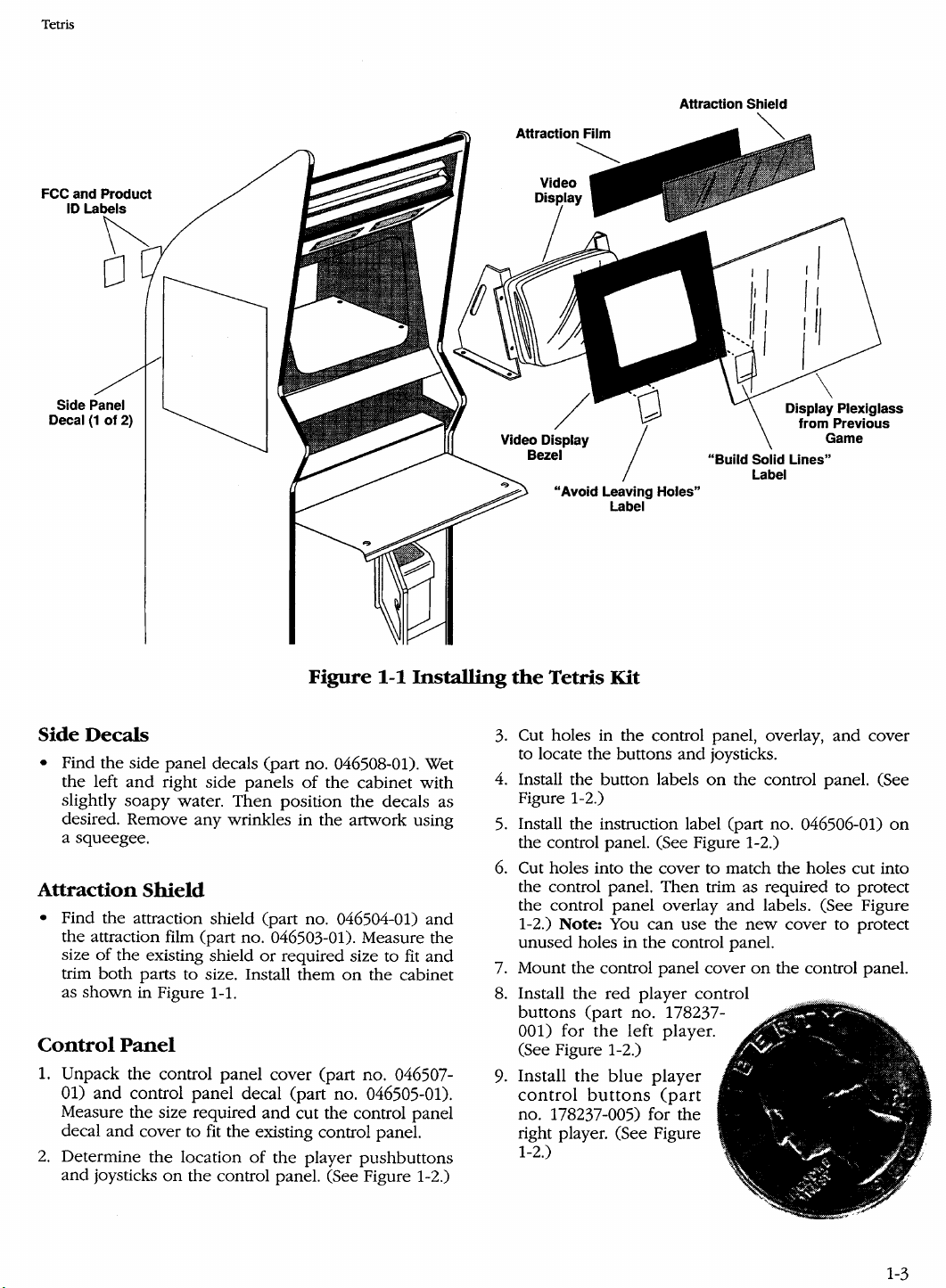
Find the display bezel (part no. 046502-01). Measure the size
quired
bezel to size. (See Figure 1-1.)
2.
Place
the
046511-02) in
ners, respectively,
1-1.)
Product ID
• Place
the
and
FCC
the cabinet.
J.JeScription
Te~~M~;~p¢~A;,~.·'ii~pl~ce~bl~pirts
ontliisibOardaridtheiI: l()cationsare:··
.•..•
TetfiSj>rograw
·····TetrisGraphics~OM
...•
EARO.MIC·ar65F
...SLAPStICICit
...
POKEY
RAMICif40B
...
....
····95(j2AMi(:t(jpr9c~ss9qTC;<lr§6E····
Assy;JAMMAH<lrne~s
B~zt!lll)isplay
La»el, Bezel
eZe1
U¥1;13
•••
Pilm{AUraction.w!.GraphiCs
Shield, AttraCtion
l)e<:a,I,~()nt:(()l
.
G6ei;ibi;waion
COY(!f,
Control Panel
Decal, Side Panel
pt
rabel;
..
Label;
Instructioris,·TetdsKitIIlStallation •
Joysti~k;
Button
BU1:tohASsy,
Microswitch, Snap-Action, ",,I Gold
tacts(4)
Bag, Anti-Static, Air Cap
PilIl},
Standoff, LcStyle,Nylon (4)
Screw,.Type.AB,Cross~Recesse<i,#6
3/4"Lg. (4) . .
Bolt,Cariiige,Blk;"i10~24X:l!i.~g
N\lt,PolyLock;tI'~0::24(12)
.
Tape,~olypropyleIle,qear,2"
aquantityollea.c!J,~ceptwbere
odl.l
FCC
...
+Position,.1.251.'13Ik.Knob
Assy,lted
Barrier,
the
Bezel
of
the existing display bezel
size to fit
bezel
and
Tetris
label (part no. 039450-01)
and
labels
the
lower
of
the display bezel. (See Figure
FCC
product
RQMI¢:ic45F
4()F
IC;
at35H;35](2)
.....
........
•.
...••............• . •.........
..
• .
~anel
(2)
D
ct
r
:
(2)
Blue
(2)
Air
cap
Kit Parts
cut
the
cardboard
(part
nos. 046511-01
left
and
Label
ID
(part
leat
35A
.....
..................
Wide
or
lower
right cor-
no. 038158-01)
on
the back
.....
...
(2)
Con~
.·x
..
(12)
.
the re-
display
and
.
of
1-2
Page 11
Tetris
FCC and Product
10
Attraction Shield
Attraction Film
Side Panel
Decal
(1
of 2)
Side
Decals
• Find the side
the
left
and
slightly
soapy
desired. Remove
Figure
panel
decals (part no. 046508-01). Wet
right side panels
water.
Then
any
wrinkles in the artwork using
of
position
1-1
the
cabinet with
the
decals as
a squeegee.
Attraction
Shield
• Find the attraction shield (part no. 046504-01)
the attraction film (part no. 046503-01). Measure the
size
of
the existing shield
trim
both
parts to size. Install them
as
shown
Control
1.
Unpack
01)
in Figure 1-1.
Panel
the
and
control
control
panel
Measure the size required
and
decal
2.
Determine
and
cover to
joysticks
the
on
location
the
or
required size to fit
on
the cabinet
panel
cover (part no. 046507-
decal (part no. 046505-01).
and
cut the control panel
fit
the existing control panel.
of
the
player
pushbuttons
control panel. (See Figure 1-2.)
Installing
3.
4.
5.
6.
and
and
7. Mount the control panel cover
8. Install
9.
Display Plexiglass
from Previous
Game
"Build Solid Lines"
"Avoid Leaving Holes"
the
Tetris Kit
Cut holes in
Label
the
control panel, overlay,
to locate the buttons
Install the button labels
and
Label
and
joysticks.
on
the control panel. (See
cover
Figure 1-2.)
Install the instruction label (part no. 046506-01)
the control panel. (See Figure 1-2.)
Cut holes into the cover to match the holes cut into
the control panel. Then trim as reqUired to protect
the control
1-2.)
unused
buttons
001) for
panel
Note:
You
overlay
can
and
use the
holes in the control panel.
the
red
(part
the
player
no. 178237-
left player.
control
labels. (See Figure
new
cover to protect
on
the control panel.
(See Figure 1-2.)
Install
control
no. 178237-005) for
the
blue
buttons
player
(part
the
right player. (See Figure
1-2.)
on
1-3
Page 12

Tetris
Control Panel
Cover
Red Buttons
After buttons are securely
tightened on
place
a small amount
on two
keep
the
from
the
the
or
three areas
buttons
top.
Joysticks
1.
Unpack
final assembly
tation
handle if
the
joysticks (part no. 171089-101). Perform
of
the joysticks using the documen-
included
you
with them. Use
have a
short joystick handle if you have a metal
control panel.
Figure 1-2
NOTE
placed
control panel, you can
of
clear
RTV
silicon
of
the locknut
from
being unscrewed
the
long joystick
wooden
control panel
Mount
the
joystick as-
sembly
base
control
securing
the
parts:
Converting
and
to
and
the
on
the
panel
following
it
by
with
the
Control
• 10-24 x 1 inch carriage bolt (part no. 75-5116B)
• 10-24 poly locknut (part no. 177010-240)
General
Skip to
ready
1.
2.
3.
Grounding
equipped
Find the
install it.
Refer to Table 1-2,
wiring information.
Connect the
harnessing. You can
by butt soldering. (The following describes the butt
soldering technique.)
Panel
Harness
with a
JAMMA
JAMMA
Installation
the
Cabinet
JAMMA
harness (part no. A046501-01)
JAMMA
harness to existing
do
if
your
cabinet is al-
harness.
Pin
Assignments, for
component
this using crimp splices
CAUTION
Make sure that
ed
correctly
the
wire
to
the
JAMMA connector.
inputs are connect-
and
or
1-4
Page 13

Page 14

Installation
4.
Try using the existing connectors. Cut the original
wire approximately 3 inches from the original con-
nector. Strip off about one-half inch
tion.
5.
Slip
the
stripped.
6.
Solder the
the original wire
shrink
tubing
new
wire designated for that position to
you
over
just stripped.
the
of
the insula-
wire
you
just
Connecting
1.
Connect the designated wires to the coin switches
and
meter.
2.
Connect the
on
the
power
3.
Be sure to clean
nisms.
Coin
power
supply outputs for the coin
Door
door
lamps to the appropriate voltage
supply. Some games have separate
and
Wires
lubricate the
door
lamps.
old
coin mecha-
Tetris
WARNING
Do
not simply tie
can cause nagging intermittent problems
through loose connections, oxidation, or
both, or a
7. Slide shrink tubing
Melt shrink tubing
wire connections. Do not
unravel
tem.
8.
Use wire tie wraps
net
where
Connecting
1.
Connect
power
+ 12V The
voltages
used
wires.
2.
You will notice that there
each
voltage. You must
called
help to ensure that you
connector
Connecting
Connect
and
BLUE
wires.
fire
and
cause problems with the electrical sys-
it seems necessary.
Power
the
supply. You will
new
used
out
in the footnotes
and
Video
the
wires designated for
video guns along with the sync
the
wires together. This
in
the
electrical system.
down
over
the
soldered wire.
around
and
all uninsulated in-line
use
electrical tape.
secure the cable to the cabi-
It
can
Wires
wires
that
are
designated
need
a supply
game
may
not
require all
in the original game. Tie off any un-
is
more than
double
do
cause it to burn.
Display
up
of
Table 1-2. This will
not overload the edge
Wires
the
of
one
some
RED,
and
for
your
+5V
and
of
the
wire for
wires as
GREEN,
ground
NOTE
JAMMA provides only negative composite sync. Most video displays accept negative
composite
sync. If your video display requires sepa-
rate positive sync, see page
manual or call
Customer Service.
Connecting
Find the two wires (twisted pair) that are designated
for the
speaker
Speaker
and
or
TELEHELP
Wires
hook
them up.
separate
3-1
at Atari Games
positive
of
this
Grounding
Find
the
line. Connect this
coin
door, control panel,
supply. This
protection. This
or
larger.
Cabinet
Do the following before plugging
1.
Apply
lowing voltages. If
power
any further.
•
+5
connector
• +12 volts
nector
2.
Check that the display has
glow
tube.
3.
Check that the attraction shield lamp has power.
4.
Check that
properly. Now
Tetris Printed-Circuit
1. Find
and
standoffs to secure the
feet.
2.
Connect the 56-pin connector to the
label
PCB.
Table
3. Apply
PCB
fer to Chapter
on
what
Testing
The Tetris kit tests itself
ble indications
and
controls. Self-test information
the
Cabinet
ground lead
is
System
power
and
volts
on
of
the filament inside the neck
the
Tetris
install it
on
the same side as the components
The connector
1-2
shows the
power
functions.
to do.
~reen)
lead
of
the
115V input
in
daisy-chain fashion to
video
display,
a safety requirement
AC
ground must
be
Checkout
in
the Game
to the game,
any
correct the
pins 3,
on
the
4,
pins F
system ON/OFF switch functions
turn
off
Game
inside
is
JAMMA
to
the
If
a video picture is
3,
Troubleshooting, for suggestions
and
check for the fol-
voltage
problem
C,
and 6 of
the
PCB
the
keyed for
game. Check that
is
before proceeding
and D of
the 56-pin
power
power
Board
PCB
Installation
(part no. A044809-0l)
cabinet.
through its mounting
proper
pin
assignments.
After Power-Up
and
provides visual
of
the condition
of
the game circuitry
is
for
the players'
of
#18
incorrect, remove
the 56-pin
by
observing the
of
to
the
Use
PCB
not
displayed
power
the
and
power
AWG
wire
PCB:
PCB
PCB
con-
the picture
game.
the
nylon
with the
on
the
orientation.
the
Game
present, re-
and
audi-
on
the
1-6
Page 15
Page 16
Installation
Tetris
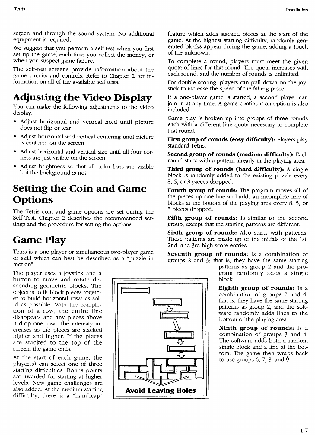
Accounting
LEFT COINS
RIGHT
COINS
2 PLYR STARTS
EASY STARTS
MEDIUM STARTS
HARD STARTS
CONTINUES
o PLY TIME
1 PLY TIME
2 PLY TIME
Tetrls™
Location:
Date:
Information
Game
Statistics
______
_______________
Minutes:Seconds
0:00-0:15
0:15-0:30
0:30-0:45
0:45-1:00
1:00-1:15
1:15-1:30
1:30-1:45
1:45-2:00
2:00-2:15
2:!5-2:30
_
_
AVG. GAME TIME
2:30-2:45
2:45-3:00
3:00-3:15
3:15-3:30
3:30-3:45
3:45-4:00
4:00-4:15
4:15-4:30
4:30-4:45
4:45-5:00
5:00-5:15
5:15-5:30
5:30-5:45
6:00-12:00
Photocopy tbis
TM
Sphere, Inc.
If!
1988
page
for
use
at
and
@ 1987, AcademySoft-Eiorg. All rigbts reserved. Tetris licensed to
Atari Games
multiple locations.
CO/po
All rights reserved. Original concept, design,
Andromeda
and
program
12:00+
Software lid.;
by
Ale.xry Pazhitnov
and
sublicensed
and
to
Vadim Gerasimov, respectively.
MIRRORSOFI'LTD
and
Page 17
Page 18
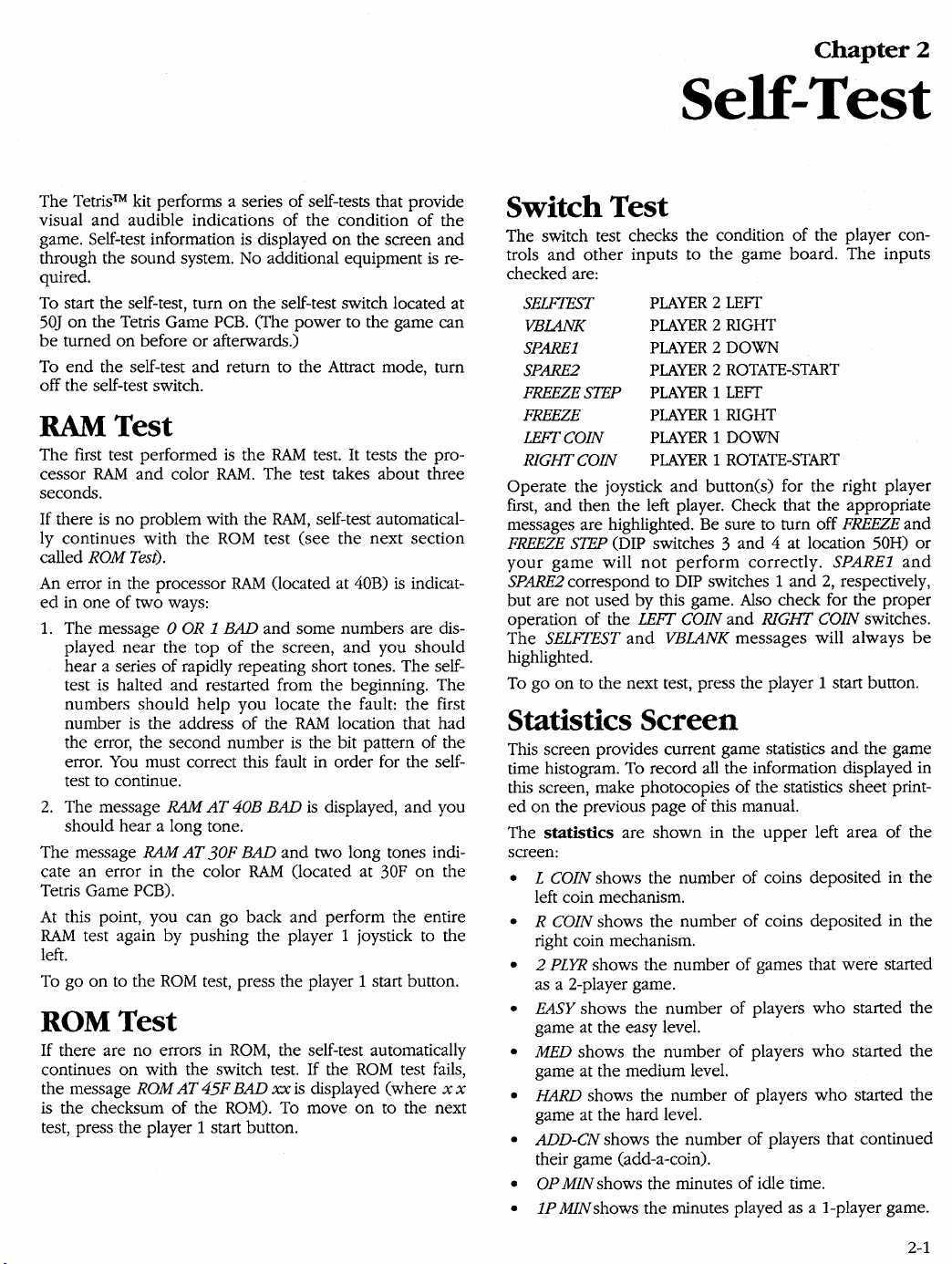
Self-test
Tetris
•
2P
MIN
shows the minutes played as a 2-player game.
•
AVG
shows the average game time in minutes
seconds.
The
game
time
histogram
screen. The histogram shows the length
in 15-second increments, except as indicated.
All
statistical information is accumulated from the last
time the statistics were reset.
the player 1 joystick to the right, the player 2 joystick to
the left, and press the player 2 start button. The message
WORKING
screen will
To
go
appears
be
redrawn with all values zeroed.
on
to the next test, press the player 1 start button.
for
is
shown in the middle of the
of
games played
To
reset the statistics, hold
about
6 seconds
and
then
and
the
Coin Options
The coin options screen indicates the current coin option
settings
Push the player 1 joystick left or right to select which option to change. Push the player 2 joystick left or right to
change the values
factory default
• COIN MODE indicates the current cost of each game.
• The
• BONUS
To
nal settings, press the player 2 start button.
and
is
used to change those settings.
of
the selected option. Note that the
of
each option
RIGHT
and LEFT MECH MULTIPllER options each
allow you to set various coin denominations.
ADDER
reward players
time. The option
of
the BONUS ADDER selections.
cancel the coin option changes
is
used to vary coin denominations or
who
of
is
highlighted in green.
insert more than
Free
Play
is
also included as one
and
one
restore the origi-
coin at a
the high-score table after 2000 games if no player has
200
achieved a high score in the last
To
cancel the game option changes and restore the origi-
nal settings, press the player 2 start button.
Press the player 1 start button to set the selected options
on
and go
tions screen by turning off the self-test switch will
the selected game options.
EEROM
The
certain areas of the
the player 1 joystick left or right to move the red box to
the desired option. Note that the factory default
option
• RESET HIGH-SCORE TABLE sets the High-Score Table
entries to the defaults stored in
•
SET
and
ROM.
• INI11AIJZE EEROM initializes the data in
should
EEROM
accounting information.
To cancel the
nal settings, press the player 2 start button.
Press the player
sets
seconds to perform the requested resets. If you exit from
the
switch,
to the next screen. Exiting from the game op-
Reset Options
EEROM
and
EEROM
reset options screen is used to clear
EEROM
is
highlighted in green.
OPTIONS TO FACTORY DEFAULTS sets the coin
game options to
only
use
device located at
EEROM
1 start button to perform the selected re-
go on to the next screen.
reset
screen
none of the reset options will
(nonvolatile memory). Move
the
factory defaults
this
when
65F
reset options
by
turning
games.
not
set
or
set
of
each
ROM.
stored
EEROM.
you have replaced the
because this clears all
and
restore the origi-
It
may take
be
up
off
the
performed.
in
You
to eight
self-test
NOTE
If
you replace the
if
a hardware problem occurs, the coin op-
tions change
Press the player 1 start button to set the game for the options selected
the coin options screen by turning off the self-test switch
not
will
and
set the game for the selected coin options.
to
go
EEROM
the
on
to
at location 65F
default (green) settings.
the next screen. Exiting from
or
Game Options
The game options screen indicates the current game option settings
the player 1 joystick left or right to select which option to
change,
change the value of the selected option. Note that the
factory default of each option
• DIFFICULTY controls the overall difficulty level of the
game.
•
ATTRACT
played during the Attract mode (once every
• AUTO HIGH-SCORE-TABLE RESET automatically resets
2-2
and
is
and
push
MUSIC controls
used to change those settings. Push
the player 2 joystick left or right to
is
highlighted in green.
whether
or
not
10
music
minutes).
is
Video Display Tests
You
can use the following tests to adjust the video display:
• Screen Pattern Tests
Move the player
among the convergence, color purity, and several
other screen patterns. Press the player 2 start button
to change colors within each pattern.
• Color Test
• 256-Color Test
To move from one test to the next, press the player
start button.
1 joystick left
or
right to select
Audio Test
of
The audio test indicates the condition
sound-effects circuits.
SOUND NUMBER indicates the sound selected by moving
the player 2 joystick left (decrements number)
(increments number). To hear the sound, press the player
2 start button one or more times. Pulling the player 2 joy-
stick down (towards you) silences the audio.
Pressing the player
Test portion of the self-test.
1 start button returns to the Switch
the music and
or
right
1
Page 19

Page 20

Troubleshooting
No
Sound
• Check
• Check for
• Check the wiring from the
• Check the
Bad
• Check the wiring to the speaker for
• Check
the
tor.
ly
811)
between
Sound
nections.
the
volume control adjustment.
proper
speaker
sound
voltage
the +
with another speaker.
for
on
the
PCB
to the speaker.
low
resistance (approximate-
and
- tabs.
PCB
edge connec-
bad
solder con-
No
Switch
• Check the ground connections to the switches.
• Check
proper
for
• Check
proper
Switch
• Check the wiring
for
• Check the wiring for shorts
Coin
• Check the wiring to the coin meter.
• Check that
meter.
Input
the
connection.
the
operation.
Operates
proper
orientation.
Meter
wiring
between
switches
Incorrect
between
Doesn't
+5V
to +12V is
the
with
an
the
between
Function
on
PCB
and
ohmmeter
Function
PCB
and
switch inputs.
the
+ side
switches
to verify
switches
of
Tetris
the
3-2
Page 21

Page 22

)I\.
ATARf
GAM
E S
Atari
Milpitas. California 9503&.1110
Games
675 Sycamore Drive
(408) 434-3700
Corporation
 Loading...