

.
_·\<
•: :·;, '
- -
...
_. ,-.
.. -......
..-..
..
--
~;
-~;.:~:r :.:
·_
.
.:_
SM144
MONOCHROME
MONITOR
FIELD
SERVICE
MANUAL
~
ATARI

:-
'
!CONTENTS I
SPECIFICATIONS
.........................................................................
2
SAFETY
PRECAUTIONS
...........................................................
3
TIMING
CHART
.............................................................................
4
HOW
TO REMOVE REAR CABINET FOR SERVICE
......
5
CONTROLS LOCATION
.............................................................
6
CIRCUIT DESCRIPTION
............................................................
7
DESCRIPTION OF
SIGNAL
CABLE .
.......
....................
...
.......
8
GEOMETRIC DISTORTION
......................................................
9
SERVICE
ADJUSTMENTS
.....................................................
10
ALIGNMENT
LOCATIONS
.......................................................
11
DESCRIPTION OF
ALIGNMENT
LOCATIONS
...............
12
TROUBLESHOOTING GUIDE
...........................................
13-17
BLOCK
DIAGRAM
......................................................................
18
TRANSISTOR &
IC
BASING
.................................................
19
·~.
--------
.......
: rSPECIFICATIONS I
1.
CATHODE
RAY
TUBE
14"
diagonal,
goo
defelection
Face plate: Antiglare treatment
Flat Square Tube
2.
SIGNAL
CONNECTOR
Input signals are applied through a
13
pin
"Din"
connector. The machting connector is a
13
pin
"Din"
female connector. (Refer to Fig.
3)
2-1
VIDEO INPUT
Amplitude
Signal
Polarity
Rise & Fall Time
2·2 VERTICAL
Amplitude
Blanking time
Vert. Frequency
2-3
HORIZONTAL
: 1 Vp-p TTL MIN
: Positive
: 10nS max.
:
5.0Vp-p ± 0.25V
: 0.70mS max.
: 71.2Hz
Amplitude : 5.0Vp-p ± 0.25V
Blanking time : 4mS max.
Horiz. Frequency : 35.7KHz
2-4
SOUND INPUT SIGNAL
Sound : Mono phone
Amplitude : 1Vp-p
Impedance : 47Kohm
2-5
VIDEO OUTPUT
Video Bandwidth
Rise
& Fall Time
2-6
SOUND AMPLIFIER
: 32MHz.
:
20nS max.
Frequency Response :
100Hz-15KHz(±
3d
B)
Output Power : Max 0.5W
Audio Distortion : Max, 10%
3.
POWER
SUPPLY
3-1
Power Rating
3-2
AC
Ripple
3-3
Consumption
:
AC 90-136V, 60Hz
AC
198-265V, 50Hz
: Less than 1
OOmV
:
35
watt max.
VOLTAGE CHART
.................................................................
20-21
PRINTED CIRCUIT BOARD
...................................................
22
EXPLODED
VIEW
........................................................................
23
AUDIO
CIRCUIT
.........................................................................
24
POWER CIRCUIT
FOR
220-240V
VERSION
............
25·26
POWER CIRCUIT FOR 120V VERSION
.....................
27-28
VIDEO
MAIN
AMP
CIRCUIT
..........................................
29·30
VIDEO PRE-AMP &
BLANKING
CIRCUIT
..................
31-32
HORIZONTAL DEFLECTION CIRCUIT
.......................
33-34
VERTICAL
DEFLECTION CIRCUIT
...............................
35-36
CIRCUIT
DIAGRAM
.......................... ; .................................
37-38
PACKING
DIAGRAM
.................................................................
39
REPLACEMENT
PARTS LIST
.........................................
40·43
4.
DISPLAY
AREA
Active Video Area
5.
CENTERING
Horizontal
Vertical
6.
GEOMETRY
Refer to Fig. 4
7.
LINEARITY
Adjacent character
Total character
8.
RESOLUTION/FOCUS
MAX
9.
EXTERNAL
CONTROLS
:
235mmx14
7mm
(9.25" X 5.79")
: ± 4 mm (0.16'').
: + 4mm (0.16").
- 6mm (0.24").
: 10%
:10%
:640
X 400
Brightness, Contrast, Volume(Sound), H-size,
Vsize, H-position, V-position.
Push-On (Power Switch)
10.
ENVIRONMENT
Operating Temperature
Storage Temperature
Relative Humidity
Altitude
11.
WEIGHT
(NET)
12.
DIMENSIONS
:
10
to
41°C
: 0
to
+60°C
: 5 to 80%
(noncondensing)
:
3000m (9800ft.)
: 7.9Kg(17.421bs)
:
328(W) X 318(D)
X
347(H)
mm
(12.89(W)
X 12.52(D)
x 13.66(H) inch)
3-3
DC
Output Power
: 55V ± 0.5V,
33V
± 0.5V
14V
±0.5V,
12V ± 0.5V
-2-
. . . . .
..
··
-·
··-
--~·
...
..
___ ..
".. .-
...
-··- .
r-·-·
[SAFETY PRECAUTIONS!
CAUTION: No work should
be
attempted on
an
exposed monitor chassis by anyone not familiar with
servicing procedures and precautions.
1.
SAFETY
PROCEDURES
should be developed by
habit so that when the technician is rushed
with
repair work,
he
automatically takes precautions.
2.
A GOOD PRACTICE, when working on any unit,
is
to
first ground the chassis and to use only one
hand when testing circuitry. This
will avoid the
possibility of carelessly putting one hand on the
chassis or the ground
and
the other on
an
electrical connection which could cause a severe elec·
trical shock.
3.
Extreme care should
be
used in HANDLING THE
PICTURE TUBE. Rough handling may cause
it
to
implode due to atmospheric pressure.
Do
not nick
or
scratch glass or subject
it
to
any undue
pressure in removal or installation. When
handl·
ing, safety goggles and heavy golves should be
{j
worm
for protection. Discharge the picture tube
by shorting the anode connection to the chassis
ground (not cabinet or other mounting parts).
When discharging, go from the ground
to
the
anode or use a self insulated piece
of
wire. When
servicing or repairing the monitor,
if
the CRT is
replaced
by
a type
of
tube other than that
specified under the GoldStar Part Number
as
original equipment in this service manual, avoid
prolonged exposure at close range
to
unshield·
ed
areas of the cathode
ray
tube. Possible danger
of
personal injury from unnecessary exposure
to
X-ray radiation may result.
4.
AN ISOLATION TRANSFORMER should always
be used during the servicing
of a unit
whose
chassis is connected to one side
of
the power
line. Use a transformer
of
adequate power rating
as
this
protects the serviceman from accidents
resulting
in
personal injury from electrical shocks.
f"-
. It will also protect the chassis and
its
com-
'
.•
ponents from being damaged by accidental
shorts
of
the circuitry that may be inadvertently
introduced during the service operation.
5.
BEFORE
RETURNING A SERVICED
UNIT, the ser·
vice technician must thoroughly test the
unit
to
be certain that
it
is completely safe
to
operate
without
danger of electrical shock.
DO
NOT
USE
A LINE ISOLATION TRANSFORMER WHEN MAK·
lNG THIS
TEST.
-3-
/
GROUND
lEAD
OF
MfTER
TO
AN'I'
EARTH
GROUND
SUCM
AS
A COLD WATER
PIPE
t!>QO
Q~otM
tO
WATT
RESISTOR
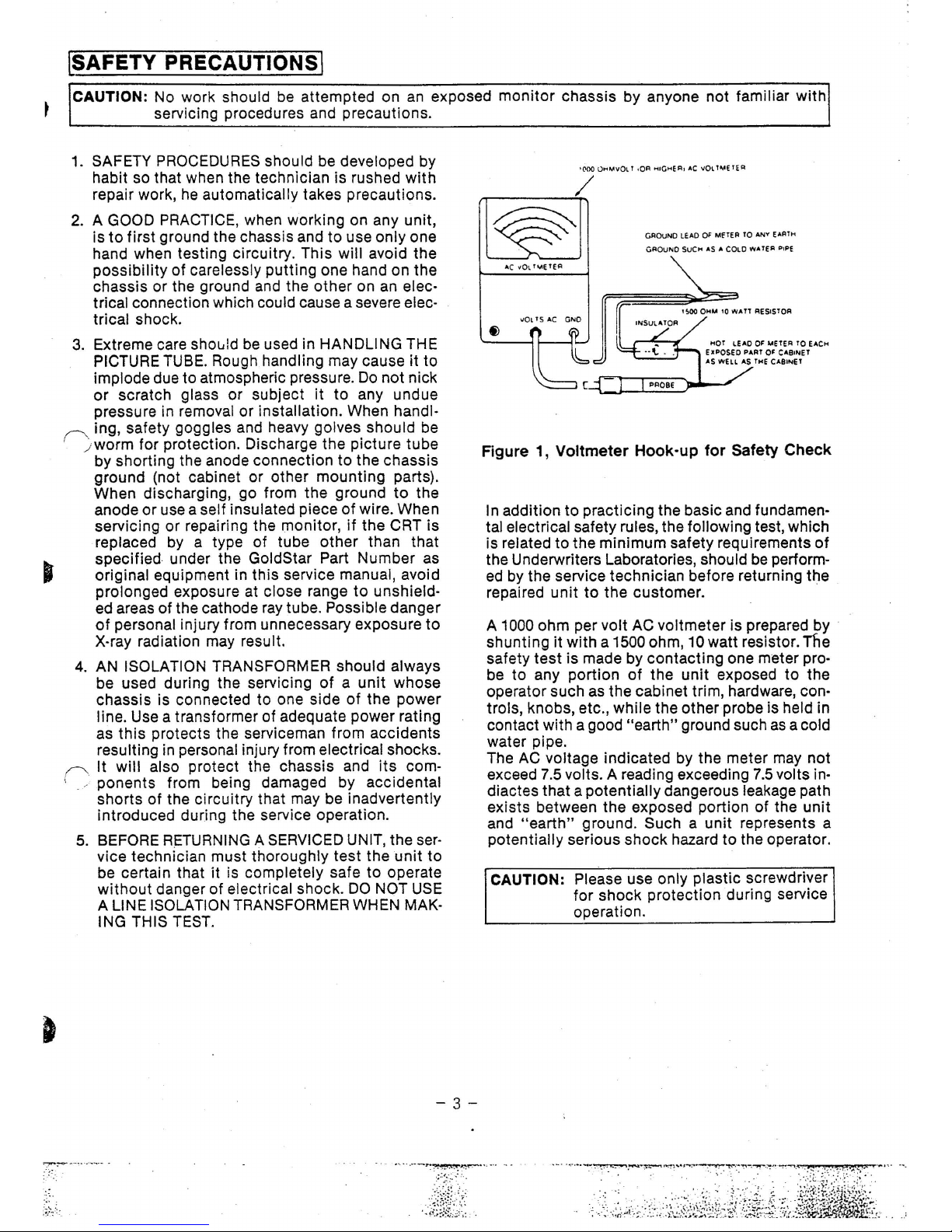
Figure 1, Voltmeter Hook-up for Safety Check
In addition
to
practicing the basic and fundamen·
tal electrical safety rules, the following test, which
is related
to
the minimum safety requirements
of
the Underwriters Laboratories, should
be
perform-
ed
by the service technician before returning the
repaired
unit
to
the customer.
A
1000
ohm per volt
AC
voltmeter is prepared by
shunting it with a
1500 ohm,
10
watt resistor. Tfie
safety test is made by contacting one meter pro-
be
to
any portion
of
the unit exposed
to
the
operator such as the cabinet trim, hardware,
con-
trols, knobs, etc., while the other probe is held in
contact with a good
"earth" ground such
as
a cold
water pipe.
The
AC
voltage indicated by the meter
may
not
exceed
7.5
volts. A reading exceeding
7.5
volts indiactes that a potentially dangerous leakage path
exists between the exposed portion
of
the
unit
and
"earth"
ground. Such a unit represents a
potentially serious shock hazard to the operator.
CAUTION: Please use only plastic screwdriver
for shock protection during service
operation.
·····.-
--~~,..,r:--·········
IFEATURESj
• 2000 characters (displays 25rows x
80
columns)
•
32
MHz bandwidth, high class
• Accepts separate
TIL
signal such as vertical sync and Horizontal sync,
TIL
Video.
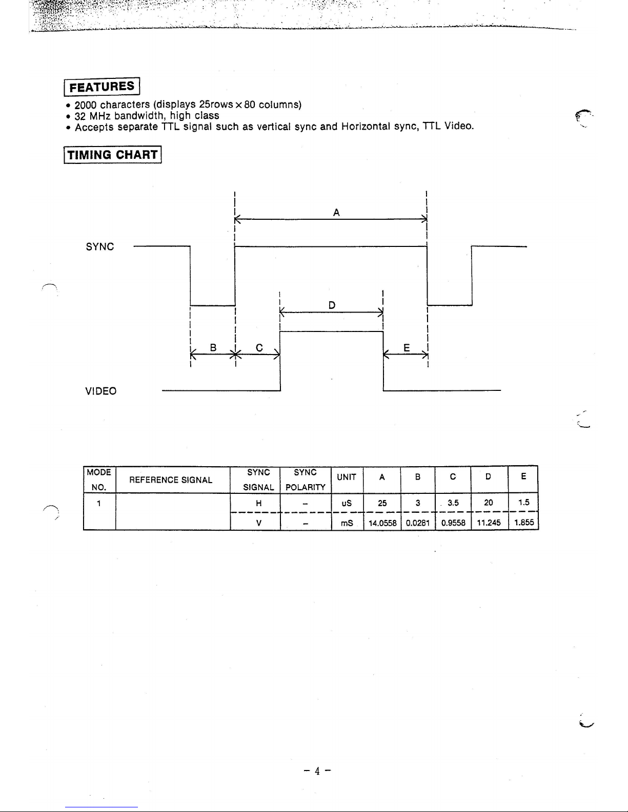
1 TIMING CHART I
SYNC
I
I
I
I
I
I
I
I
I
I
1/
B
,J,
c
'
I'
-'1"-
7
I
VIDEO
MODE SYNC
REFERENCE
SIGNAL
NO. SIGNAL
1 H
1------
v
A
I
I
D
~
I
SYNC
UNIT
POLARITY
-
uS
------
----
-
mS
-4-
I
I
1..-
A
25
---
14.0558
E
8
3
I
/1
I
----
0.0281
c
3.5
---
0.9558
D
E
20
1.5
----
---
11.245 1.855

I HOW TO REMOVE REAR CABINET FOR SERVICE I
t • Unscrew the Four screws maked
®shown
in Figure 2
JJ~~
ATARI
0
looodO
Figure
2
®
- 5. -
.
~-·:~: ~~-·~~~~~~~
..
_:·~~
·--
~-7'
:
....
-·······
......
--·-· . .. ···- · .
....
..
--~-
-
.............. ------·-
..
l
~:~-----~'!.
-·?i;·.:
-
·_
·' -...
--:-
--·?~:-:\~~~~~~~~~
.
·.·._
...
. ·._
.·
. >
..
.
...
.
. : : ·- ' . . :
~
...
. • -;
•,
-.:
~
..
~
I
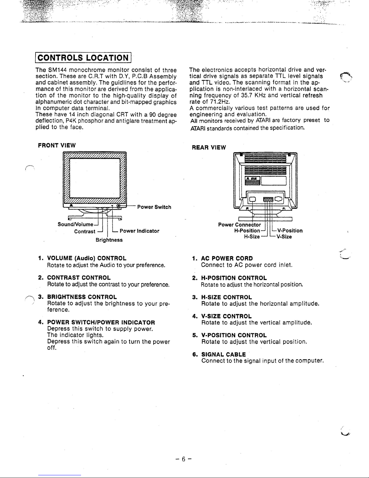
coNTROLs
LOCATION I
The SM144 monochrome
monitor
consist
of
three
section. These are
C.R.T
with
D.Y, P.C.B Assembly
and cabinet
assembly. The guidlines
for
the perfor-
mance of this monitor are derived from the
applica-
tion
of
the
monitor
to
the high-quality display
of
alphanumeric dot character
and
bit-mapped graphics
in computer data
terminal.
These have
14
inch diagonal
CRT
with
a 90 degree
deflection,
P4K
phosphor
and
antiglare treatment
ap-
plied
to
the face.
FRONT
VIEW
Power
Indicator
Brightness
1.
VOLUME (Audio) CONTROL
Rotate
to
adjust the Audio
to
your preference.
2. CONTRAST
CONTROL
Rotate to adjust the contrast to your preference.
3.
BRIGHTNESS CONTROL
Rotate
to
adjust the brightness
to
your
pre-
ference.
4. POWER
SWITCH/POWER INDICATOR
Depress this
switch
to
supply power.
The indicator
lights.
Depress
this
switch
again
to
turn
the
power
off.
. ..
....
. :
.
:':'
:·.~:t!;~~~:
..
~::·_
' . •.
The electronics accepts horizontal drive and vertical
drive signals
as
separate
TIL
level signals
and TTL video. The scanning format in the ap-
plication is non-interlaced
with
a horizontal scan-
ning frequency
of
35.7
KHz and vertical refresh
rate
of
71.2Hz.
A
commercially various test patterns are used
for
engineering and evaluation.
All monitors received
by
ATARI
are
factory preset
to
ATARI
standards contained the specification.
REAR
VIEW
Power Connector
H•Position
H-Size
1. AC POWER CORD
Connect
to
AC power cord inlet.
2. H·POSITION CONTROL
Rotate
to
adjust the horizontal position.
3.
H·SIZE CONTROL
Rotate
to
adjust the horizontal amplitude.
4.
V·SIZE CONTROL
Rotate
to
adjust the vertical amplitude.
5. V·POSITION CONTROL
Rotate
to
adjust the vertical position.
6.
SIGNAL CABLE
Connect
to
the signal
input
of
the computer.
-6-
· . . ·
.....
~
_
,.,
'\ .
.._
.. ·
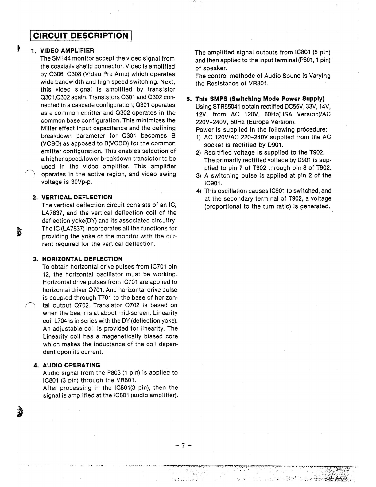
I CIRCUIT DESCRIPTION I
1.
VIDEO AMPLIFIER
The SM144
monitor
accept
the video signal from
the coaxially sheild connector. Video is amplified
by 0306, 0308 (Video
Pre
Amp)
which
operates
wide bandwidth and high speed switching. Next,
th
is video signal is amplified by
transistor
0301,0302 again. Transistors 0301 and 0302 connected in a cascade configuration; 0301 operates
as a common
emitter
and
0302
operates in the
common base configuration. This minimizes the
Miller
effect
input
capacitance and the
defi~ing
breakdown parameter for 0301 becomes B
(VCBO)
as
apposed
to
B(VCBO) for
the
common
emitter
configuration. This enables sel_
ection
of
a higher speed/lower breakdown
transistor
to
be
used in the video
amplifier
. This
amplifier
r---\ operates in the active region, and video swing
voltage is 30Vp-p.
2. VERTICAL DEFLECTION
The vertical
deflection
circuit
consists
of
an IC,
LA7837, and
the
vertical
deflection
coil
of
the
deflection
yoke(OY) and
its
associated
circuitry.
The IC {LA7837) incorporates all the
functions
for
providing the yoke
of
the
monitor
with the
cur~
rent required
for
the
vertical
deflection.
3.
HORIZONTAL DEFLECTION
To obtain horizontal drive pulses from
IC701
pin
12, the horizontal
oscillator
must
be working.
Horizontal drive pulses from
IC701
are applied
to
horizontal driver 0701. And horizontal drive pulse
is
coupled through
T701
to
the base
of
horizon-
0 tal
output
0702. Transistor
0702
is based on
when the beam is at about mid-screen. Linearity
coil L704 is in series with the
OY
(deflection yoke).
An adjustable
coil
is provided for linearity. The
Linearity coil has a magenetically biased core
which
makes
the
inductance
of
the coil depen·
dent
upon
its
current.
4. AUDIO OPERATING
Audio
signal from the
P803
(1
pin) is applied
to
IC801
(3
pin) through the VR801.
After
processing in the IC801(3 pin), then the
signal is amplified at the
IC801
(audio amplifier).
The
amplified
signal
outputs
from
IC801
(5
pin)
and then applied
to
the input terminal
(P801,
1 pin)
of
speaker.
The
control
methode
of
Audio Sound
is
Varying
the Resistance
of
VR801.
5. This SMPS (Switching Mode Power Supply)
Using
STR55041
obtain rectified
OC55V,
33V,
14V,
12V,
from
AC 120V, 60Hz(USA Version)/AC
220V-240V, 50Hz (Europe Version).
Power is supplied in the following procedure:
1)
AC 120V/AC 220-240V supplied from the AC
socket
is
rectified
by 0901.
2)
Recitified
voltage is supplied
to
the T902.
The
primarily
rectified
voltage by
0901
is sup-
plied
to
pin 7
of
T902 through pin 8
of
T902.
3) A switching
pulse is applied at pin 2
of
the
IC901.
4)
This oscillation causes
IC901
to
switched, and
at
the
secondary terminal
of
T902, a voltage
(proportional
to
the
turn ratio) is generated.
-7-
·":'··
..
-~
·:""""'·~
..
...
.
....,...
....
. -
.........
~.
~
..
.
. ';.;
..
:::
.:
~
.
:;·:
.. : :; :··
+
;
.-
>
;l{~~i
t£:·,
..

·-;*~~~
~~w~
~~
~~07F;~xn'<
4
r:r:
·
')'':..
~---··,
·.-·
·· ...
··
· ·
~-:-:
_.
~_~_·:
·_
··:.·
:·
.·_
:_·_,
_::
·.
~._:
..
·
.~
;_:_~,
_
;·
_
.
__
.~
:·.::::_
~-~:
·
_F
_
..
~:~·-·_·./·~_
:·
~,-.:_
.·
:.
~_:;_=,·
_~
_:_:~_-
_
:_·
_.::.~_~
..
~
.•
.
~
.::,
__
:_~--
.
--~_~
..
·_:_:
._ ..
~_,:
·-"'.
_
......
·.··
•.~
::_
.. -._.
·_;
__
:~_
.. ·_.:_·
.• : __
··.··
·· ·
·:
__
.·_._-.· _·
_·._.·.
_· .
_.
- _· :'_:
_·
.. .;-_· ·
.......
-:\·
· -
;·
_2
.mf-:?5;~~12
~t::·
.. ·,.·
:::
.
.:.~"--
-
·.;.-..
-·
.
._:-...;;........:...;...
__
,..:...:.
~.......:..;..--
--
... _ .. --.
·.:_;~
__
--~-
_-- -
.....:..:..
~~~
--
-
-.
-~---
- ·
~-
I DESCRIPTION OF SIGNAL CABLE I
1.
13
PIN CONNECTOR (MALE)
TO
THE COMPUTER
PIN
SIGNAL
NAME
PIN SIGNAL NAME
4
1
1
Audio
8
GND
2
Not used 9
H-sync
8
5
3
Not used
10
Not used
4 GND
11
Video
12
9
5
Not used 12
V-sync
6
Not used
13
GND
7 Not used
13
2. 6 PIN CONNECTOR
ON
THE P.C.B
3. 3
PIN CONNECTOR
ON
THE P.C.B
P401
P803
1 2 3 4 5 6
2
3
000000
0 0 0
I I
J
1
PIN SIGNAL NAME
PIN
SIGNAL
NAME
1
GND
1
AUDIO
2
VIDEO
2
Not
used
3
GND
3
GND
4
H-sync
5
V-sync
6
GND
Figure
3.
Signal
Connector
Pin
Assignments
-8-
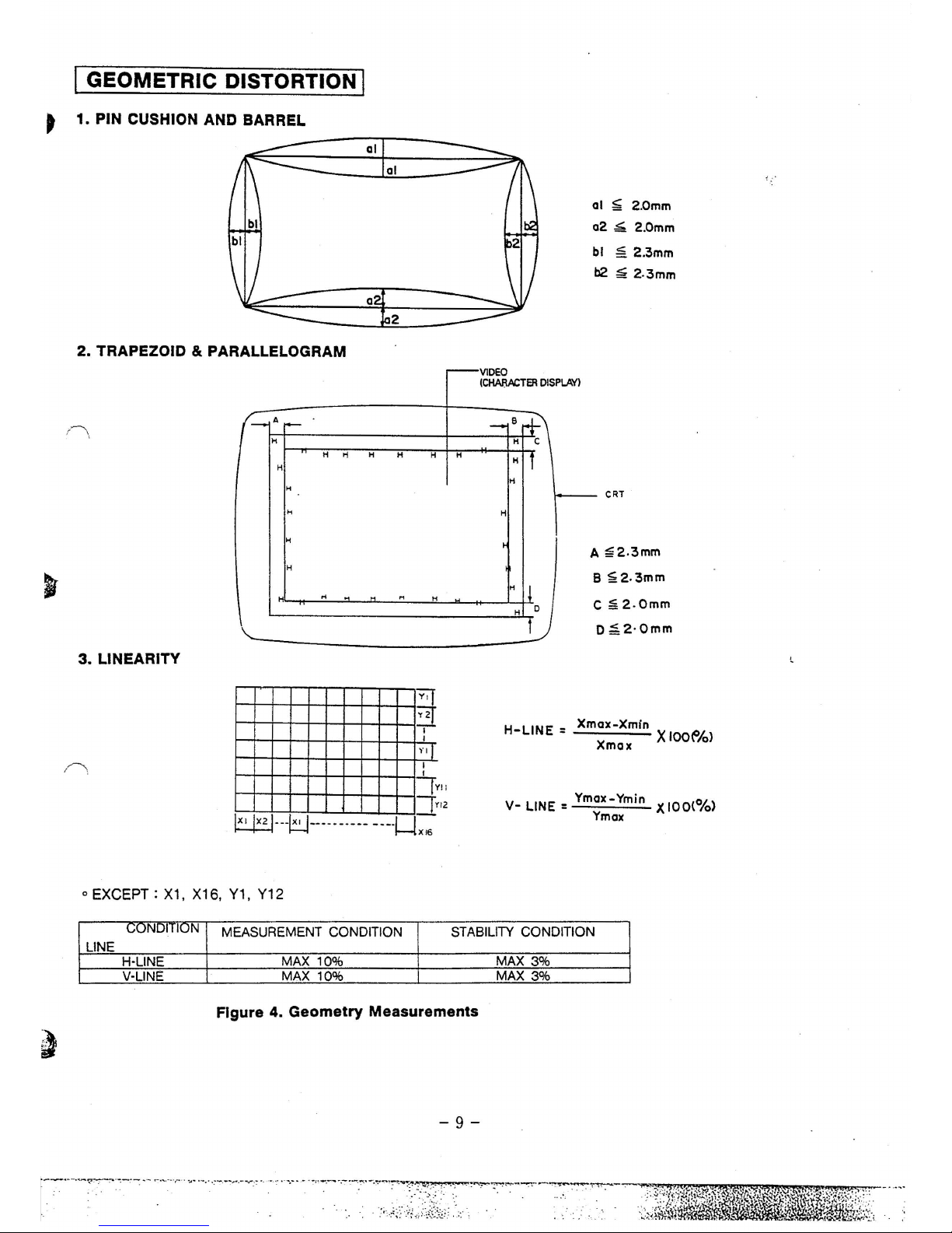
I GEOMETRIC DISTORTION I
~
1. PIN CUSHION AND BARREL
--------~--------
2. TRAPEZOID & PARALLELOGRAM
al ~ 2.0mm
a2
~
2.0mm
bl ~ 2.3mm
b2 ~ 2.3mm
~VIDEO
t
\.
(-:-
.
H
H
H
H H
H
H
H
H
H
H
M
...
...
3. LINEARITY
Y.J
~
I
I
Yll
I
I
ly
JY
~
---
~---- ·
-···-
-·-·1-!X16
o EXCEPT:
X1, X16,
Y1,
Y12
H
!i
12
ICHAI'IACTER
DISPLAY)
-e+~
H
c
H f
H
H
~
H
!!
H
D
1
1----
CRT
A
~2.3mm
B
~2.3mm
C ~
2.0mm
0~2·0mm
H-LINE
: Xmax-Xmin
----
X
IOO(%>
X max
V-
LINE:
Ymax-Ymin X
100(%)
Ymax
CONDITION
MEASUREMENT CONDITION STABILITY CONDITION
LINE
H·LINE
MAX
10%
MAX
3%
V·LINE
MAX
10%
MAX
3%
Figure 4. Geometry Measurements
-9-

·w·f•"'~'-t<3-lf.:'·~i',-
· •' ,
•.
,,..,,~
-
· · ·'
·
-~~zttwJ.~rt!.~t -:
:'
.~:
·~~)~~~~'f:
-
.
:
~~:
-
.
:'
-..
--..:. ~
~~2~·
::
..
:
:~~~:-·
. -· ...... •••
..
. . ··•
~·
-·r•
·-·-
..... :.
·
'-'--~-
~---·· ·~···--··--
•
· •
~--
·--·-..:i,;•
:-:
;::_~:;,{:;i
·'--·
--
-··
•• • • •"• ·-
-·-
-··
·· ,;_,_.,.
____
.._
...
- ·
w£!..o-.::
.....
- ....
..
_-l.-
•---·-~·
~
·
.... · ·-
I SERVICE ADJUSTMENTS I
NOTE:
ALL GEOMETRY MEASUREMENTS SHOULD
BE
PERFORMED
AT
THE DISPLAY ADJUSTEDT0230
mm WIDE AND
165
mm HEIGHT AFTER WARMING
UP
THE MONITOR
FOR
30
MINUTES.
1. H-HOLD ADJUSTMENT
1-1.
Set the H-position VR702
to
the mechanical
center position.
1·2.
Display white over the entire screen.
1-3.
Turn the H-hold
VR701
until
the picture is
almost-stable.
2.
HORIZONTAL
AND
VERTICAL CENTERING
ADJUSTMENT
2-1.
Adjust centering magnet (on
the
DY)
that the
(-
. picture to
be
mechanical center.
2-2.
Display the cross hatch pattern screen.
2-3.
Adjust H-position VR702
until
the picture is
positioned at the center
of
screen.
2-4.
Adjust V-position
VR605
until the picture is posi-
tioned at the center of screen.
3.
HORIZONTAL
AND
VERTICAL SIZE
ADJUSTMENT
NOTE:
Before
attemping
adjustment,
adjust
brightness volume to be
30
± 8FL in Full
white pattern, at
this
time contrast volume
is maximum.
3·1.
Adjustment
of
horizontal size.
3·1·1. Display cross hatch pattern screen.
3·1·2. Adjust the H-size VR704
until
the picture
size become 230 mm.
3-2.
Adjustments
of
Vertical Size
3-2-1.
Display cross hatch pattern screen.
3·2·2. Adjust the V-size VR603
until
the picture
size becomes 165 mm.
4.
VERTICAL
LINEARITY & HORIZONTAL
LINEARITY
ADJUSTMENT
4-1.
Display the cross hatch pattern screen.
4-2.
Adjust
VR604
(V-Lin,
Volume)
to
the best condi-
tion.
4-3.
Check
the vertical linearity when the nonlinearity
is
within
10%
on
all
signal
with
cross hatch pat-
tern.
4-4.
Adjust
L704
(H-Lin
Coil)
to
the best condition.
4-5.
Check
the Horizontal linearity when the nonlin-
earity
is
within 10%
on
all
signal
with
cross hatch
pattern.
5.
DISTORTION ADJUSTMENT
5·1.
Display the cross hatch pattern screen.
5-2.
Adjust clic:tortion magnet
(on
the
DY)
to
meet
Fig. 4
G~ometry
measurements.
5-3.
Adjust side pincnshion or Barrel co,;
tml
v~lume
(VR707)
to meet Fig. 4 Geomertry measurements.
6.
BRIGHTNESS AND CONTRAST
Set
the Sub-Brightness control
VR705
to
disappear
of
the backraster; when external brightness control
knob is positioned at the maximum.
Thereafter, set external contrast volume
to
max posi-
tion and control internal contrast volume
(VR710)
to
30FL at center screen.
The contrast control is used
to
vary the data
brightness level
as
dicated by ambient lighting
conditions.
7.
FOCUS ADJUSTMENT
Adjust the focus control volume
(VR301)
for best over
all focus
of
test
pattern (Display
with
all
"H"
character). Usually the center and corners
of
the
screen do not focus at the same setting and a
com·
promise must be made.
-:-10-
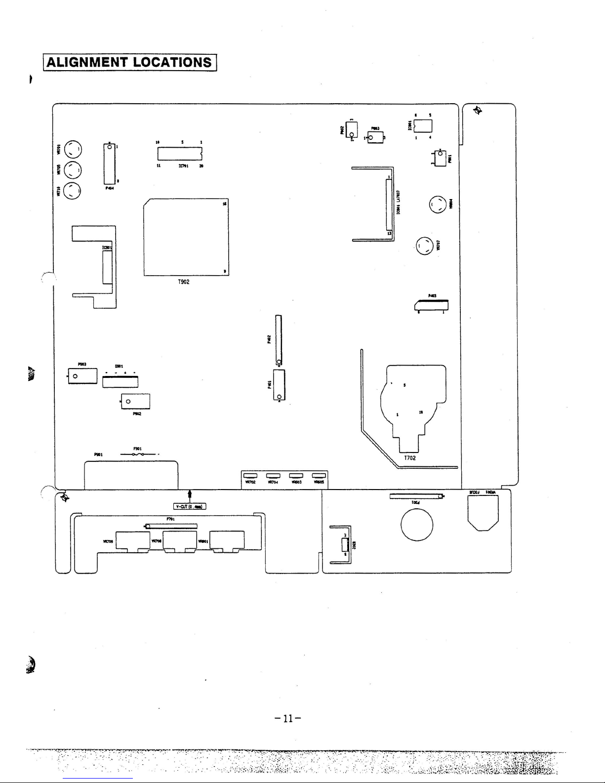
!ALIGNMENT LOCATIONS I
I s
'$-
i[J
-
ftD
-
1-D
I
•
i()
0:
"
s
I
I
l
t]i
;()
II
11:?11
..
I
·o
....
~
- I
i "
Ql
/
:l
II
ft
ll
~
()i
r
I
L-
T902
'---L_
...
(
I
•
I
-
..
1
~~
EJ,·
..
·D
I
s
EJ
-
1
"
...
I
....
T702
1
rr=J
r=J
r=J
;I
"""'
..,..
_,
,._.;
r
~
•
RC:I
11QM.
.....
0
v-arr o.-.1
0
~
,...........
,,
..
r
]}
~[
l--f
]-·[
J
~U
~
-ll-
·
--=----~
~
~
-~
"="~~~~--~ __,_:
~·~
----~~-·-
·
:.~
.7-r:.~'-~.
=-:./.-
.
..
·.·
~.-·-
.:~
.1;:
~ -'
·
__
:_~:.
·
.·.
·
·.-·~·~.
- -.··
--
_:.
.
..
~:7
: ·
·~·
.·
·
~·:-
~.
~
1\7T?}:
y\:::-
..
\''::
~~-~-:-:-.:
-.:~~-
:/I.
~·;:,
t-\,~~
i~~~
t--~s--·
-
' .. · .·
•··
·
:{.,;o;·
:~~~~
i::i(
{
j;
',;l;)
;$ttJl•.i~~\~
m;
t.i
&::.;
...
·.,.
':

·:~~~--
·-n~
~;~r~
~:~-~~~~;:
t~:\~l::
::_· - -~·.
:
_·.
.
,.
. .
.. _ -.:..
. · .•
b'-
...
_.
:.·.~~-J~
~-
.....
~i~~~-i.:.,
·.:.:
~
-·
.
....
::
...
::
~...,..;.
·
..;,;.
·
_-..:.
- -~.:.:;;·~
:-
;._
__
I DESCRIPTION OF ALIGNMENT LOCATIONS I
1. Main P .C.B
Marking
Description
Marking
Description Marking Description
VR701
H-Hold
VR
IC701
H-Deflection IC
P403
From D.Y(Deflectior
VR705 Sub-Bright
VR
IC601
V-Deflection IC
Yoke)
VR710 Sub-Contrast
VR
IC801
Audio AMP IC
P802
To
Control Volume
VR604 V-Linearity
VR
0901
Bridge Diode
P.C.B(P701)
VR707 Side Pincusition
VR
IC901
SMPS
Control
P803
From Signal Cable
VR702
EXT
H-Position
VR
Switching IC
P801
To Speaker
VR704
EXT
H-Size
VR
P901
AC Socket
VR603
EXT
V-Size
VR
P903/904
To Power Switch
VR605
EXT
V-Position
VR
P401
From Signal Cable
T902 Power Trans
P402
To CRT Socket
T702
F.B.T(Fiy Back Trans)
P.C.B
(P301)
F901
Fuse
P404
To Control Volume
P.C.B
(P701)
2. Control Volume P.C.B
Martc:lng
Description
VR709
EXT Brightness
VR
VR708
EXT Contrast VA
VR801
EXT Sound
VR
P701
From Main P.C.B
P404 & P802
3. CRT Socket P.C.B
Martc:lng
Description
VR301
Focus
VR
0302
Video
AMP Out
P301
From Main P.C.B
P402
-12-

I TROUBLESHOOTING.GUIDE I
Problem 1.
NO
POWER
(Cause)
Trouble in the power circuit
IC901,
0901
and
its
external elements are faulty.
( \
NO
POWER
YES
TROUBLE
IN
PRIMARY
OTHER
COMPONENTS
NO
NO
NO
NO
NO
NO
-13-
TROUBLE
IN
POWER
CORO
TROUBLE
IN
FUSE
F90
1. 1.6A/2SOV
TROUBLE
IN
0901
TROUBLE
IN
IC901
STRS5041
TROUBLE
IN
0901
TROUBLE
IN
SMPS
SECONDARY
B
LINE
SHORT
SSV
. 33V.
14V.
12V
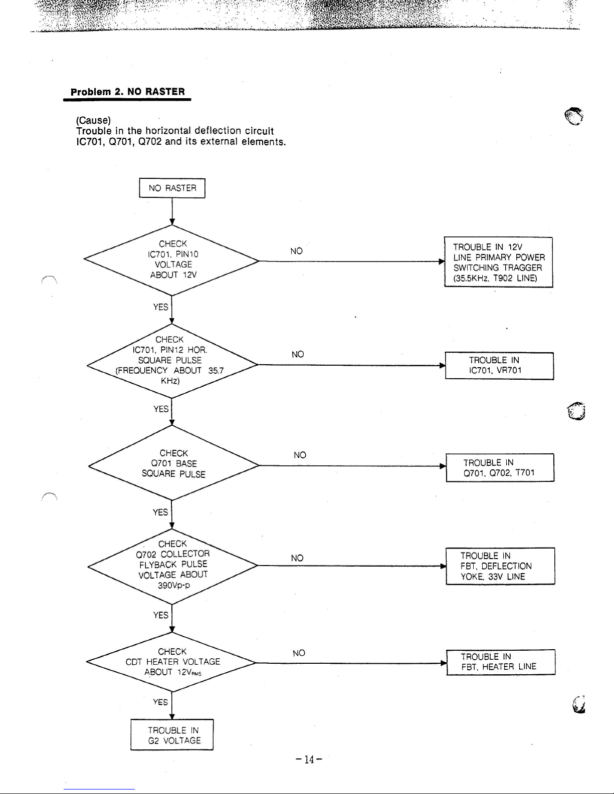
Problem 2.
NO
RASTER
(Cause)
Trouble in the horizontal deflection circuit
IC701, 0701, 0702
and
its external elements.
NO
RASTER
YES
TROUBLE
IN
G2
VOLTAGE
NO
NO
NO
NO
NO
-14-
TROUBLE
IN
12V
LINE
PRIMARY
POWER
SWITCHING
TRAGGER
(35.5KHz.
T902
LINE)
TROUBLE
IN
IC701,
VR701
TROUBLE
IN
0701. 0702.
T701
TROUBLE
IN
FBT,
DEFLECTION
YOKE.
33V
LINE
TROUBLE
IN
FBT.
HEATER
LINE

Problem 3.
NO
IMPROPER HORIZONTAL
OR
VERTICAL SYNCHRONIZATION
(Cause)
1)
Defective horizontal sync.
IC701
and its applied parts are faults·.
2)
Defective vertical sync.
This is due to a failure
of
the vertical oscillator.
(IC701
and its applied parts), or applied parts of the IC601.
NO
CHECK
THE LINE
OF
BETWEEN
PIN
401
AND IC701
PIN
1
CHECK
IC701
NO
AND
12V
LINE
TROUBLE
IN
HOR.
TROUBLE
IN
OTHER COM-
PONETS
OR
VER.
SYNC
YES
-15-
NO
TROUBLE
IN
SIGNAL CABLE
PIN
401
TROUBLE
IN
0601
TROUBLE
IN
IC701 AND
12V
LINE
 Loading...