

Page 1
SAN FRANCISCO
RUSH 2049’”
SAFETY, SPECIFICATIONS,
INSPECTION
NOTICE: This manual is subject to change without notice. Atari reserves the right to make
improvements in equipment function,
manufacturing methods may warrant.
Fill out and mail in the Game Information Card. Include the game serial number from the label
on the rear of the cabinet. For your records, write the game serial number in the manual.
&
INSTALLATION
design, or components as progress in engineering or
Page 2
SAFETY INSTRUCTIONS
The following safety instructions apply to operators and service personnel. Read these instructions before
preparing your game for play. Other safety instructions appear throughout this manual.
DEFINITIONS OF SAFETY TERMS
DANGER
WARNING
injury.
CAUTION
injury. CAUTION also alerts you about unsafe practices.
NOTICE
A
8
indicates imminent hazard. If you fail to avoid this hazard, it WILL cause death or serious injury.
indicates a potential hazard. If you fail to avoid this hazard, it COULD cause death or serious
indicates a potential hazard. If you fail to avoid this hazard, it MAY cause minor or moderate
indicates information of special importance.
WARNING: TRANSPORTING GAMES. This game contains glass and fragile
electronic devices. Use appropriate care when transporting this game. Avoid rough
Y
‘I
handling when moving the cabinet. Don’t move this game with the power on.
WARNING: DISCONNECT POWER.
before attempting service or adjustments. Installing or repairing PC boards with power
ON can damage components and void the warranty. Be sure that you securely install
ground wires.
WARNING: GROUND GAMES.
have inspected and properly grounded it. Only plug this game into a grounded,
wire outlet. Don’t use a
WARNING: AVOID ELECTRICAL SHOCKS.
an isolation transformer. Internal cabinet AC isn’t isolated from the external AC line.
%heatef
Always turn the power OFF and unplug the.game
Avoid electrical shocks! Don’t plug in a game until you
plug, or cut off the ground pin on the line cord.
This video game system does not utilize
three-
0
WARNING: HAZARD TO EPILEPTICS. A very small portion of the population has a
condition which may cause epileptic seizures or momentary loss of consciousness
I
0
A
when viewing certain kinds of flashing lights or patterns that are present in our daily
environment. These persons may experience seizures while watching some kinds of
television pictures or playing certain video games. People who have not had any
previous seizures may nonetheless have an undetected epileptic condition.
If you or anyone in your family has experienced symptoms linked to an epileptic
condition (e.g., seizures or loss of awareness), immediately consult your physician
before using any video games.
We recommend that parents observe their children while they play video games. If
or your child experience the following symptoms: dizziness, altered vision, eye or
muscle twitching, involuntary movements,
convulsions, DISCONTINUE USE IMMEDIATELY and consult your physician.
1-2
loss of awareness, disorientation, or
you
Page 3
FRAGILE
El
1
l
A
A
A
I
l
A
Y
WARNING: HANDLE FLUORESCENT TUBE AND CRT WITH CARE. If
YOU
drop a
fluorescent tube or CRT and it breaks, it will implode! Shattered glass can fly eight feet
or more from the implosion.
CAUTION: CHECK POWER SELECTOR, LAMP. Set the 110/220VAC selector on the
power supply for the correct line voltage. Check the selector setting before switching on
the game. Verify that the fluorescent lamp assembly is correct for the local line voltage.
CAUTION: USE PROPER FUSE. Avoid electrical shock! Replacement fuses must
Abe
of the same type as those they replace. Fuse voltage and current ratings must match
ratings on the original fuse.
CAUTION: ATTACH CONNECTORS PROPERLY. Be sure that printed circuit board
(PCB) connectors mate properly. If connectors don’t slip on easily, don’t force them. A
reversed connector may damage your game and void the warranty. Connector keys
only allow a connector to fit one set of pins on a board.
CAUTION: USE CARE WHEN SHIPPING HARD DISKS. The hard disk drive must be
packed in an anti-static bag. When shipping the drive for repair or replacement, pack it
in an approved container (P/N 08-8068). Never stack or drop hard disk drives.
PRODUCT SPECIFICATIONS
Operating Requirements
Location
Domestic 120VAC @ 60Hz 4.0 Amps
Foreign
Japan
Cabinet Statistics
Shipping Dimensions
Main Cabinet
Width 37.5” (95 cm)
Depth 37.0” (94 cm)
Height 70.5”
Equipment Characteristics
Video Display Monitor
VGA Resolution RGB
27” (68.6 cm) CRT
Game Characteristics
Rayer
1 to 8 players per race (with linking)
Choice of vehicle and course
High Score Recognition
Electrical Power
230VAC @
1OOVAC @
Variables
5OHz
50Hz 4.0 Amps
(179 cm)
2.0 Amps
Temperature
32°F to 100°F
(0% to 38°C)
Shipping Dimensions
Seat/Pedestal
Width 26.0” (66
Depth
Height 52.0” (132 cm)
Audio System
Digital
Two 3.5” (9 cm), Two 5.5”
(14 cm), One 8” (20 cm)
Operator Variables
Coinage, Game Options,
Difficulty, Force, Volume,
33.0”
5Speaker
cm)
(84 cm)
Sound
Audits, Statistics
Humidity
Not to exceed 95% relative
Shipping Weight
All Cartons
6oxed
Currency Acceptors
2 Coin Mechanisms, Coin Counter
Dollar Bill Validator Ready
Electronic Coin Acceptor Ready
Diagnostics
Automatic Power-Up Self-Test
Manual, Multi-Level Menu System
475
Ibs.
(215 kg.)
1-3
Page 4
PRODUCT CONFIGURATION
Stand-Alone Units
Each game is ready to play right out of the shipping carton. Use the game menu system to set player
variables in advance, or you can accept the factory settings and leave the choices to the players.
Tandem Units
Linking allows players to compete against each other (on one course). Operator menus are the same as
in stand-alone games. Linking cables to connect games are factory installed. Use the crossover couplers
included in the spare parts to link two cabinets. Hardware is for attaching cabinets together is provided.
Cabinet Arrays
I Icn =
VU” u 8”
Refer to the inside rear cover for more information about the optional Hub Linking Kit.
Iqai
nntwnrk to connect more cabinets together. Network hubs can interconnect up to eight games.
-, . .-...
-
INSTALLATION & INSPECTION
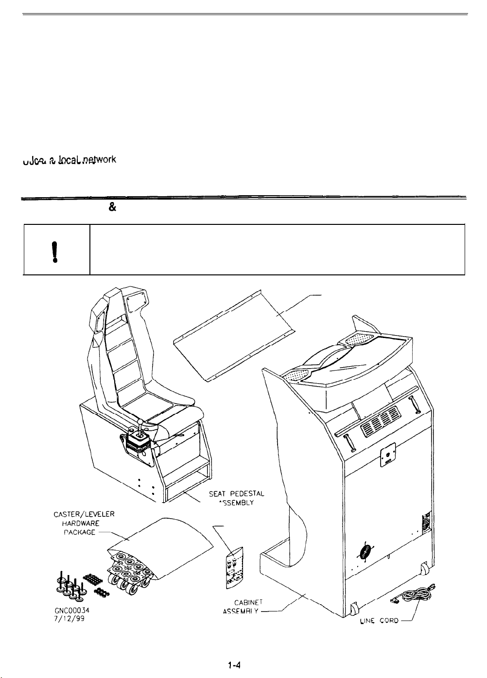
WARNING: The cabinet is top-heavy. Use the handles when moving cabinets. Don’t
push against plastic parts. Don’t raise the marquee light box until instructed to do so.
Installation of the casters, leg levelers, and marquee bracket requires two individuals.
MARQUEE BRACKET
A
I
0
7/l 2/99
SPARE PA RTS
MAIN
CABINE
GAME UNPACKED AND READY FOR ASSEMBLY
Page 5
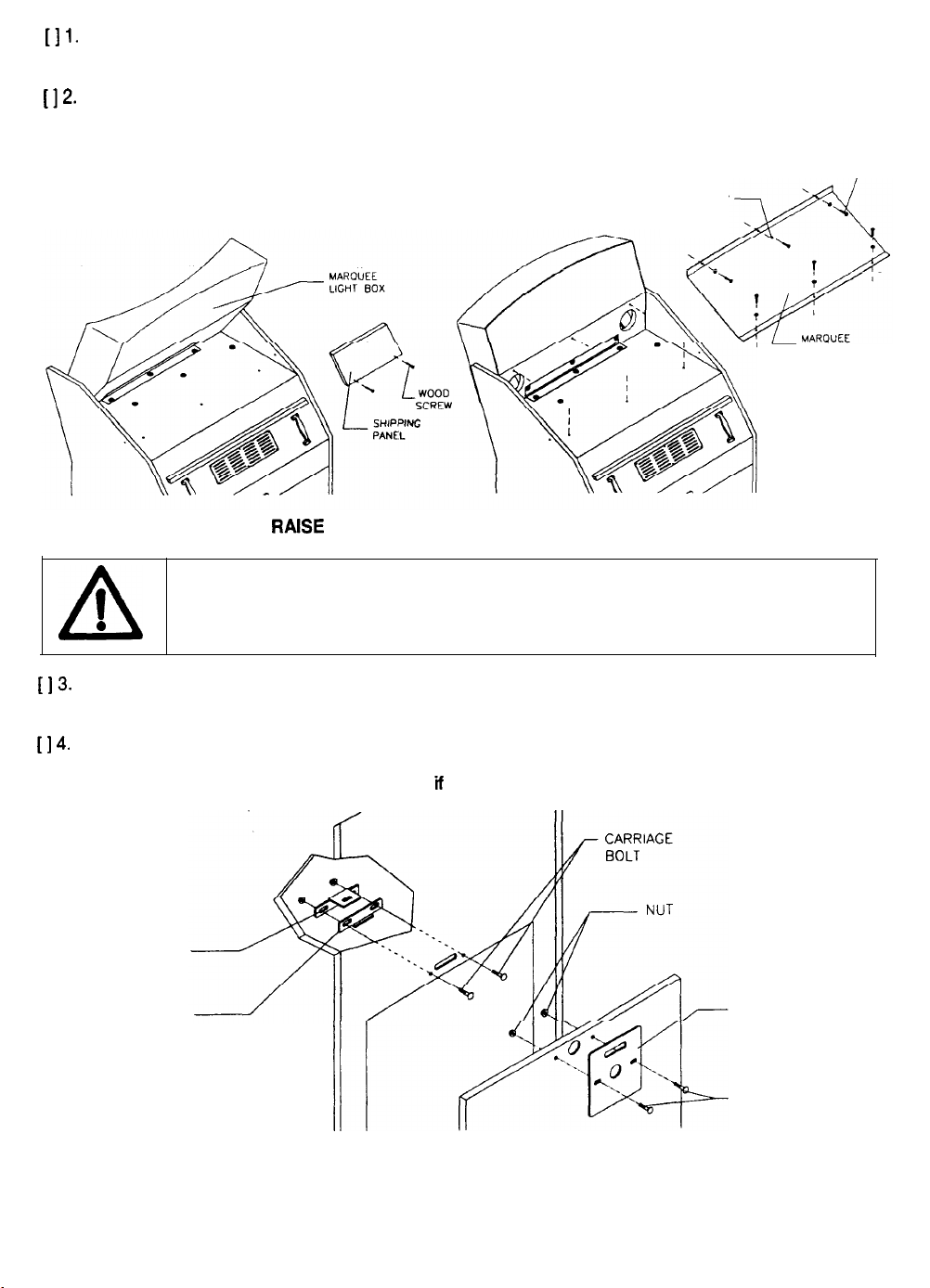
[I
Remove and set aside items from the shipping containers. Remove all packing material. Inspect
1.
for damage. Check the main cabinet exterior, pedestal, shifter, and all of the seat surfaces.
[12-
A
Remove the keys from the steering wheel. Unlock and open the coin and cash doors. Electrical
cords, mechanical components, and game spare parts are packed inside the cash box.
I
0
TAMPER RESISTANT SCREW
FLAT WASHER
RAfSE
AND SECURE MARQUEE LIGHT BOX
WARNING: The marquee light box is not secure until the bracket has been installed.
Keep tools and fingers away from the top of the cabinet to prevent damage. Have the
second individual hold the box in place while completing the following steps.
7
BRACKET
Il3-
[I 4.
Slowly lift the rear of the marquee light box. Raise until the box rests upright on the main cabinet.
Remove the screws and lift the shipping panel off the cabinet.
Orient the marquee bracket over the top of the cabinet and the back of the light box. Align the
holes. Install tamper resistant screws. Tighten each screw with the wrench from the spare parts.
Remove the bracket and reinstall the panel
HASP
BRACKET
KEY LOCK
BRACKET
CABINET SHOWN
FOR REFERENCE
CABINET SECURITY MODIFICATIONS
if the light box must be lowered for cabinet relocation.
LOCK
PLATE
CARRIAGE
BOLT
l-5
Page 6
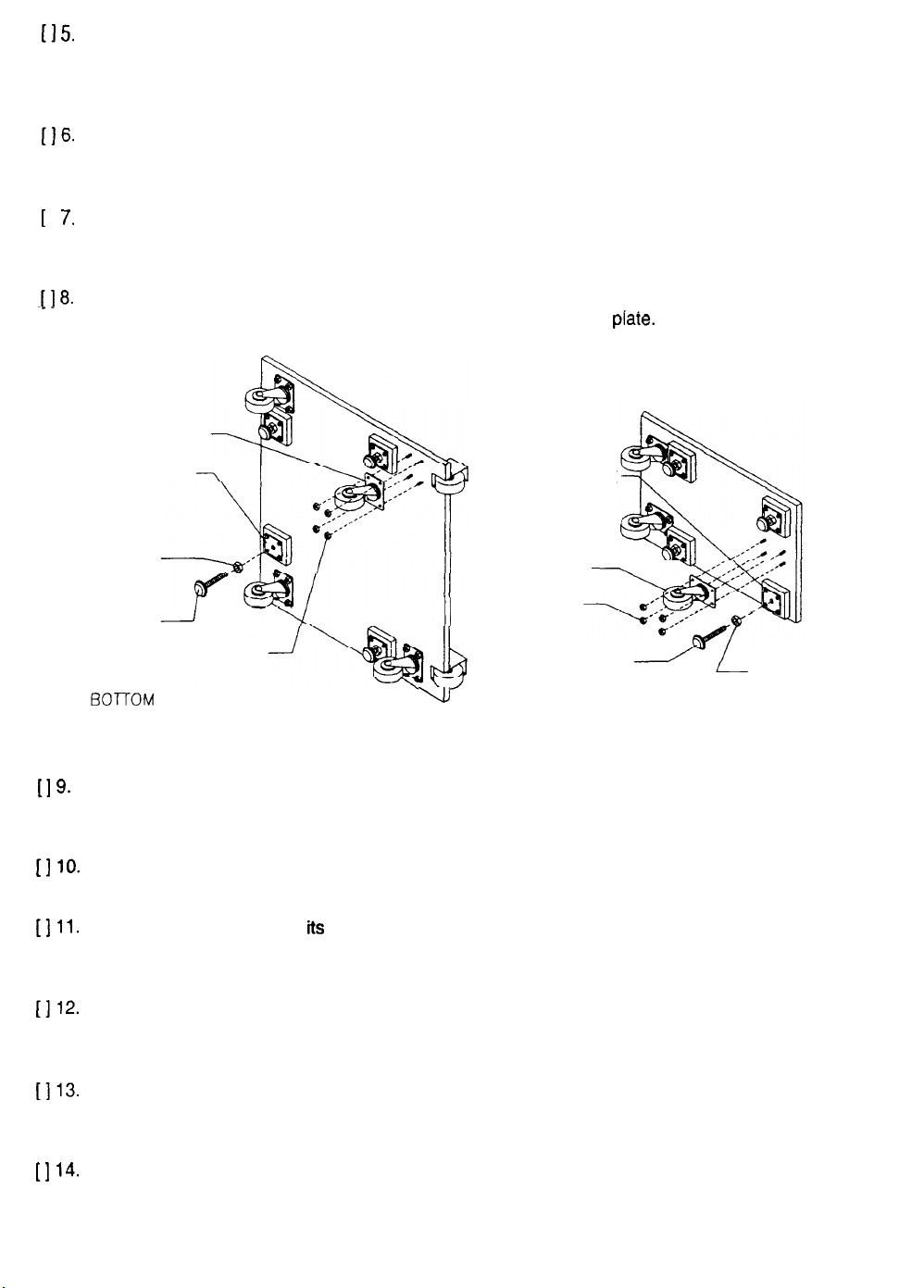
[I 5.
The hasp bracket is in the spare parts bag. Remove four screws from the sides of the cabinet rear
door. Unlock and remove the rear door. Remove the two lock bracket nuts from inside the
cabinet, above the rear door opening. Slide the hasp onto the bolts so that it protrudes from the
hole in the back of the cabinet. Reinstall and tighten nuts.
[IS.
Locate the lock plate at the top of the rear door. Remove the bolts and nuts from the lock plate.
Rotate the plate so that the slot will be above the door. Reinstall and tighten the bolts and nuts.
Now you can install an extra padlock to secure the rear door.
[
I
The main cabinet requires four swivel casters, one in each corner. Lay the cabinet on its back or
7.
prop up one side to allow caster mounting. Orient a caster plate over the threaded studs. Align the
holes and seat the plate against the wood. Install a nut on each stud. Tighten each nut firmly.
1 I 8.
The main cabinet requires four leg levelers, one in each corner. Install one nut onto each leveler.
Install one leveler and nut into the threaded hole in every ieveier
SWIVEL CASTER
LEVELER PLATE
LEVELER NUT
LEG LEVELER
BO7OM
CASTER NUT
VIEW OF CABINET ASSEMBLY
LEVELER PLATE
SWIVEL CASTER
CASTER NUT
v
piate.
Do not tighten these nuts.
LEG LEVELER
BOTTOM VIEW OF SEAT ASEMBLY
LEVELER NUT
[I 9.
[I
10.
1111.
[112-
[113.
[I
14.
ATTACHMENT OF CASTERS AND LEVELERS
The seat pedestal requires three swivel casters, one in each rear corner and one at the front
center. Lay the pedestal on its side or prop up one side. Orient a caster plate over the threaded
studs. Align the holes and seat the plate. Install a nut on each stud. Tighten each nut firmly.
The seat pedestal requires four leg levelers, one in each comer. Install one nut onto each leg
leveler. Install a leveler with its nut into the threaded hole in each leveler plate. Do not tighten nuts.
Roll the main cabinet to
its intended location. Maintain clearance between the cabinet and walls,
drapes, other games, etc. Lower each leg leveler until the cabinet is stable and level. Adjust the
levelers to raise the wheels up off the floor. Distribute the cabinet’s weight equally on each corner.
The factory ships the pedestal mounting rails bolted inside the main cabinet. Remove the two front
and two rear hex-head bolts that secure each rail. Pull the rails out, reverse them, and reinsert
them. Align the holes and reinstall the bolts.
Locate and expose the wiring harnesses inside the main cabinet and the seat pedestal. Roll the
pedestal section up to the front of the cabinet. Leave enough space to attach the wiring harness.
Mate each seat connector with its cabinet connector. Press the connectors firmly to seat contacts.
Align the pedestal opening with the rail ends. Slide the pedestal forward onto extended mounting
rails while guiding the wiring inside. Align the holes. Attach the pedestal using tamper-resistant
screws and large flat washers from the spare parts bag. Tighten the screws firmly.
l-6
Page 7
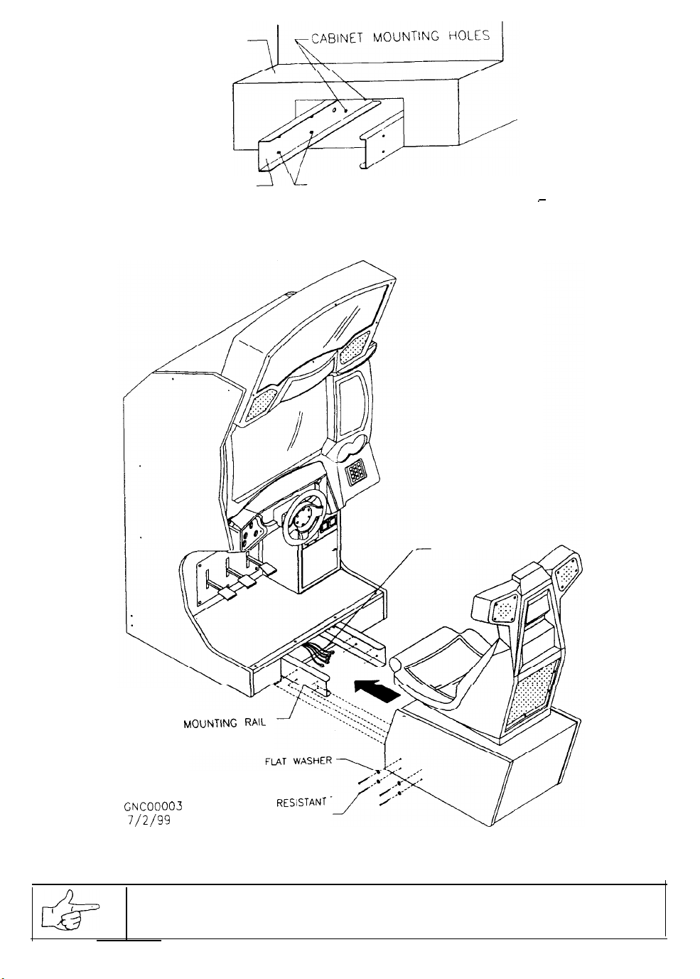
CABINET BASECABINET BASE
MOUNTING RAILMOUNTING RAIL PEDESTAL MOUNTING HOLESPEDESTAL MOUNTING HOLES (NUTS)(NUTS)
LOCATION OF PEDESTAL ASSEMBLY MOUNTING HOLES
WIRING HARNESS
--
MOUNTING
GNC00003
7/2/w
RAIL
TAMPER RESiSTANT
CAP SCREW
CABINET AND PEDESTAL ASSEMBLY
NOTICE: When you install the pedestal, carefully avoid pinching wires or connectors!
-
1-7
Page 8
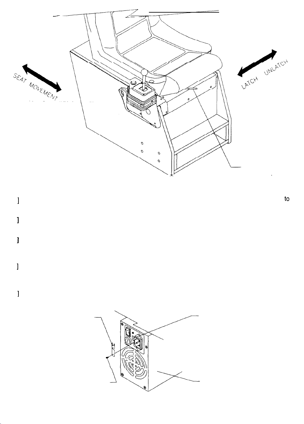
SEAT TRAVEL AND DETENT POSITIONS
SEAT POSITION
ADJUST LEVER
[ ] 15. Lower each seat pedestal leg leveler until the cabinet is stable and level. Adjust the levelers
to
raise the wheels up off the floor. Distribute the pedestal’s weight equally on each leg leveler.
[ ] 16.
Sit in the driver’s seat. Use the seat position adjustment lever to change the seat position. The
seat must move smoothly back and forth, locking securely into position when the lever is released.
Repeat the previous steps for additional cabinets. Refer to the array instructions on a following
]
17.
[
page. When all cabinets have been placed in final positions and bolted together, tighten the
leveler nuts against the plates.
]
18. To link cabinets (recommended), uncoil the linking cable and extend it out of each cabinet. Lay
[
the cable in the
notch at the bottom center of the door area. After you are satisfied with individual
cabinet operation, go to the linking setup instructions page.
[
Use a voltmeter to measure the AC line voltage. The power supply switch setting must match this
]
19.
voltage. If it is incorrect, remove the switch safety plate and change the voltage switch position.
SAFETY PLATE
VOLTAGE SWITCH
MOUNTING SCREW
LINE VOLTAGE SWITCH ADJUSTMENT
POWER SUPPLY
l-8
Page 9
L1
POWER SUPPLY
(EXHAUST AIR)
CHECK CABINET AIR FLOW
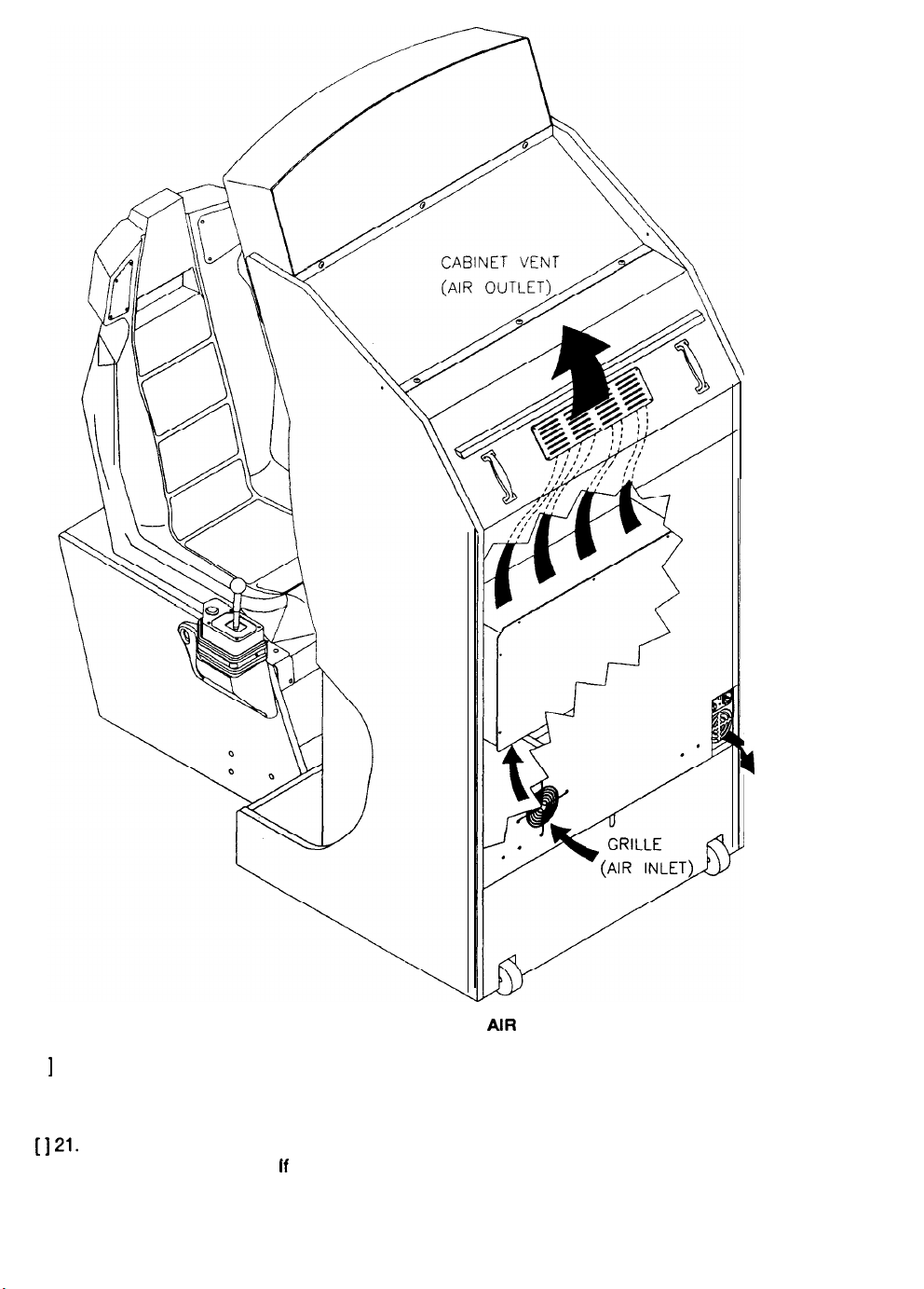
[ ] 20. Check the cabinet to be certain that the cooling fan air paths are not blocked. The power supply
has rear vents. The game electronics fan is mounted at the lower left corner of the enclosure
directly behind the rear door air inlet. Keep manuals and other documents away from these areas.
1121.
Reinstall the rear door onto the cabinet. Lock the door and remove the key. Install the screws at
If
the sides of the door.
the cabinet requires extra security, install a padlock now (not supplied).
1-9
Page 10
FLANGE GRIP NUT
SECURITY BRACKET. LEFT
(OPTIONAL)
COIN VAULT
GNC0002!
?/2/99
SECURITY BRACKET INSTALLATION
SECURITY BRACKET RIGHT
(OPTIONAL)
’
[I=
[I
23.
1124.
1125.
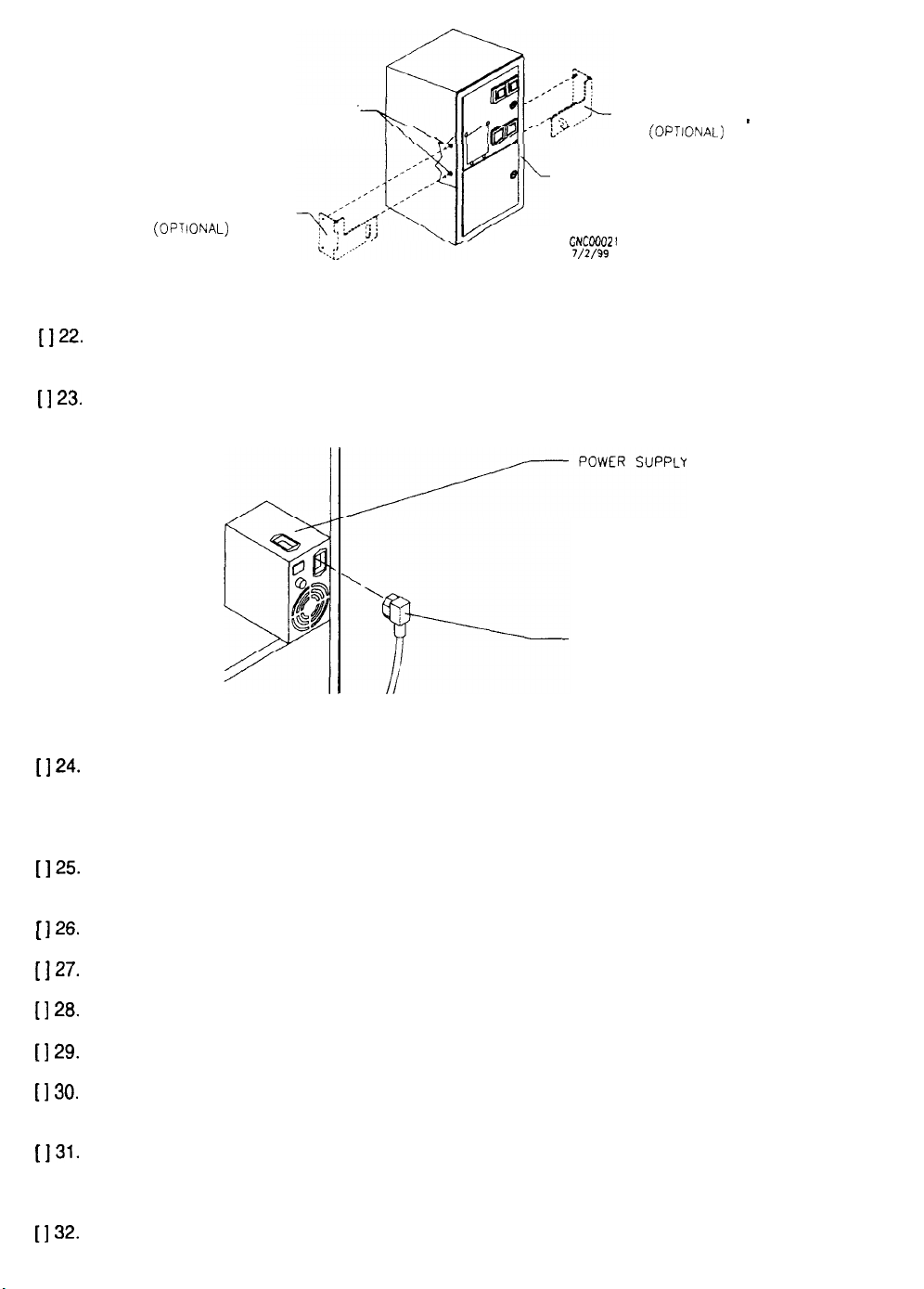
To install the optional coin security brackets, open the doors. Remove the cash tub. Remove the
flange grip nuts. Insert the bolts through the brackets and into the vault. Install and tighten nuts.
The power cord is with the spare parts. Match the holes on the IEC plug with the prongs in the
receptacle on the power supply. Push the plug firmly to seat it.
LINE CORD
LINE CORD INSTALLATION
Plug the game into a grounded (three-terminal) AC wail outlet. The master switch is on the power
supply. Turn the power on and verify that both fans function. The game will power up and begin
self-diagnostics. If diagnostics find no errors, the game enters its Attract Mode of operation.
(Attract Mode includes scenes and sounds from typical races, player’s scores, messages, etc.).
Open the coin door. The operator control switches are inside the coin vault on the outside wall.
Press the TEST MODE button to enter the Menu System. The main menu screen appears.
[ 126.
1127.
[I
28.
[I
2%
[I 30.
[131-
[I 32.
Select CONTROLS TEST at the Self Test Menu. Check that controls and lamps are functional.
Select SOUND TESTS at the Self Test Menu. Verify operation of cabinet and seat speakers.
Select MONITOR TESTS at the Self Test Menu. Verify colors, linearity, contrast, brightness, etc.
Select DISK TESTS at the Self Test Menu. Run all the tests in order to verify drive operation,
Select EXIT TO GAME at the Self Test Menu. The system should enter Attract Mode. Open the
coin door and press the SERVICE CREDITS button a few times to allow game play.
Press the gas pedal to select variables and begin play. Check steering, clutch, brake, gear shift.
Listen to the audio while playing the game. Note sound irregularities (phase problems, no low
frequencies, mono audio from stereo speakers, etc.).
Change the volume and make adjustments as necessary. Close and lock all open doors.
l-10
Page 11
CABINET
ARRA’?
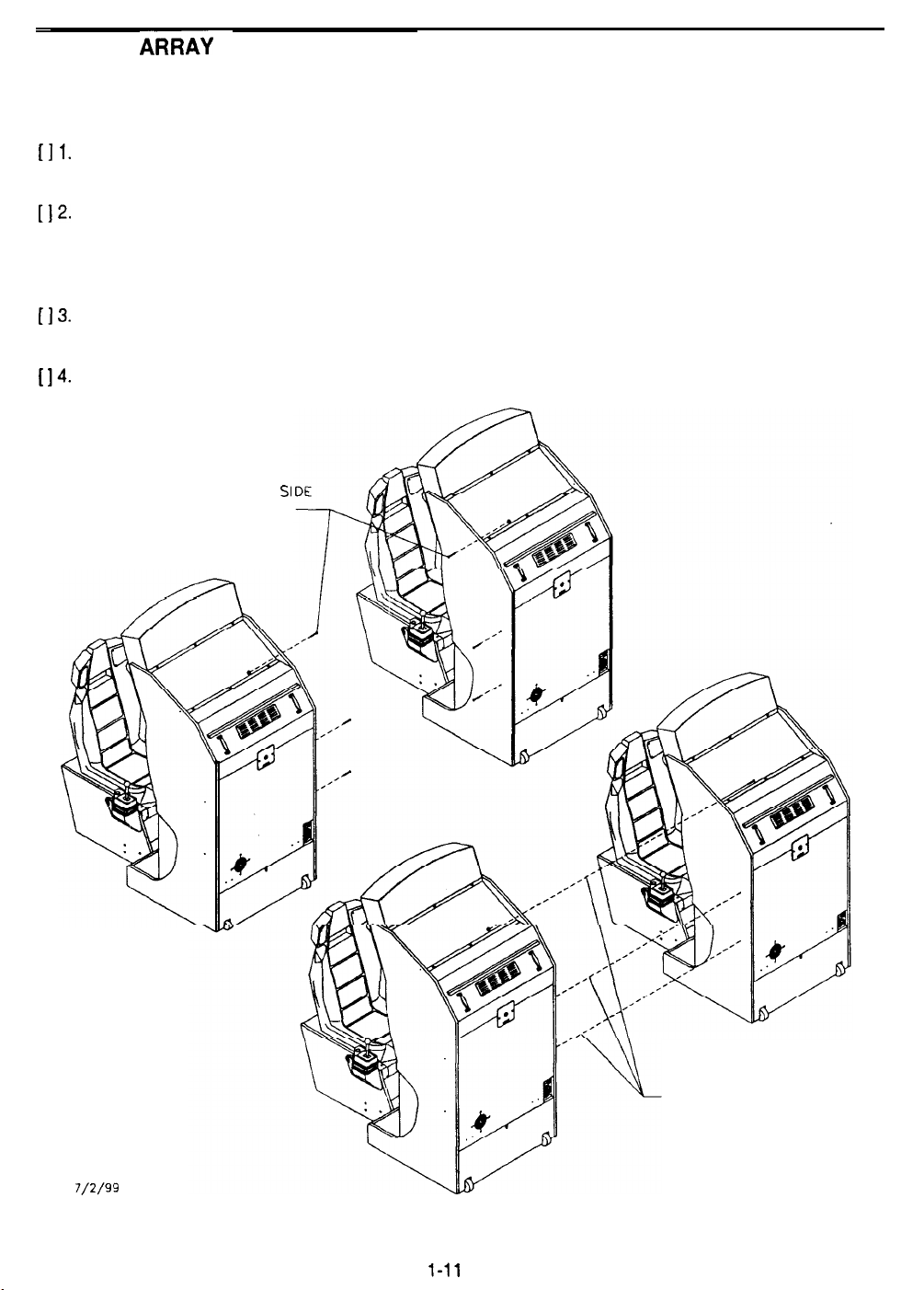
Multiple cabinets should be attached together to form a game array. Each cabinet comes with its own
mounting hardware to mechanically connect the cabinets. See the following pages for linking instructions.
[I 1.
LIZ.
[I
3.
I 14.
Install the cabinet casters, leg levelers, seat pedestal, etc., as described on previous pages. Place
the completed cabinets next to each other, leaving sufficient space to remove and install bolts.
Unlock and remove the rear cabinet door. Remove three flat head carriage bolts on the inner
sides of each cabinet, two along the rear of the adjacent sides, and one at the top center of the
side. Retain three of the flange grip nuts. Place the six bolts and the remaining three nuts in the
spare parts bag. Locate three longer carriage bolts from the spare parts.
Move the cabinets next to one another. Adjust levelers until the sides are parallel and touching
each other. Align the holes. Insert the long bolts through both cabinets. Install nuts and tighten.
Repeat these steps for additional cabinets. Install and lock the rear doors.
INNER CABINET
BOLTS AND NUTS
SI
CNCOOOO I
7/2/99
INSERT BOLTS THROUGH
BOTH CABINETS
BOLTING CABINETS TOGETHER TO FORM AN ARRAY
Page 12
LINKING
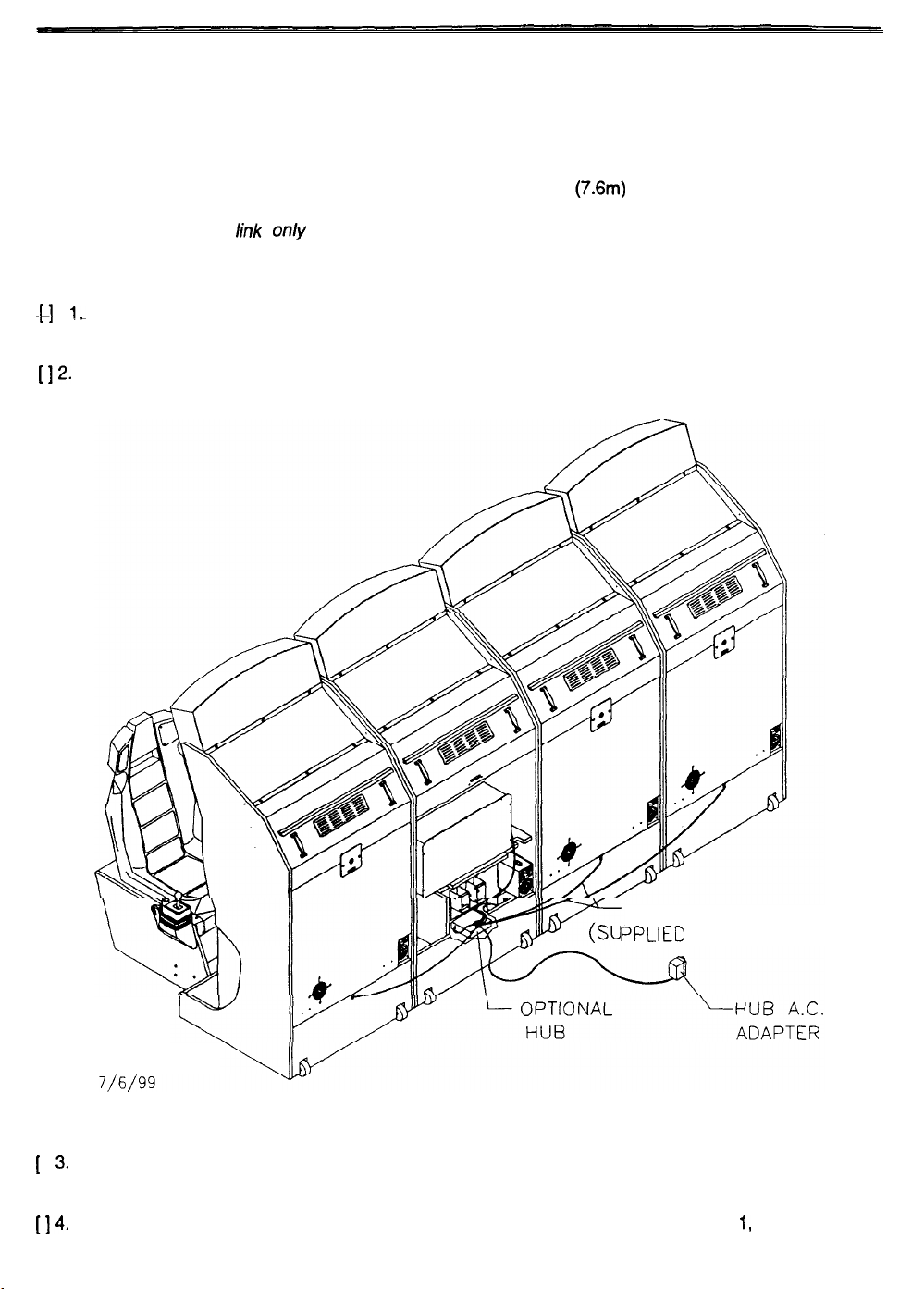
Connect games together electronically to permit simultaneous competition between players. The linking
cables are factory installed in each cabinet. Crossover couplers are supplied in the spare parts. Once
connected, games can operate individually (as before) or in linked mode as players desire.
Players quickly learn to associate joined cabinets with linked operation. If possible, attach the cabinets
together to form an array. You may separate cabinets by up to 25 ft.
A crossover coupler can link only two cabinets. Up to eight cabinets can be interconnected to form a Local
Area Network (LAN). The optional Hub Link Kit is required to manage this network. The hub has circuitry
to prevent errors from data collisions (several games sending data at the same time, etc.).
$1
IL
Insert the free end of each linking cable into a receptacle in the crossover coupler. Press firmly to
seat the contacts. The locking tab will snap into place when the plug mates properiy with tine jack.
(7.6m) if necessary.
[12-
Place the connected coupler inside one of the cabinets. Place the coupler on the floor under the
electronics. Retract any excess cable back into the cabinets so that it does not touch the floor.
1
I
[Id*
LINKING CABLE
PPLIED WITH GAME)
GNC00002
TYPICAL HUB INSTALLATION
Use a hub to link more than two game cabinets. Active electronics permit the use of long cables,
3.
allowing remote hub location. The optional Hub Linking Kit has detailed instructions.
Enter the menu system and set each linked cabinet to a different number (Cabinet 1, 2, 3, etc.).
1-12
Page 13
SAN FRANCISCO
R&H
2049’”
/
CHAPTER
FEATURES & OPERATION
NOTICE
Information in this manual is subject to change without notice. ATARI reserves the right to make improvements in
equipment function, design, or components as progress in engineering or manufacturing methods may warrant.
Fill out and mail in the Game Registration card. Include the game serial number from the label on the rear of the
cabinet. For your records, write the game serial number in the manual. SERIAL NUMBER
Page 14

L
FEATURES
PREVIEW
in
the Attract Mode, the game automatically cycles through scenes and sounds from typical races. Players
are presented with laps from several different camera angles and spectator viewpoints. Use the Preview
feature to see some of the fast grooves for curves and tunnels.
Tap the MUSIC button during any of these scenes to skip ahead to the next scene. Press and hold MUSIC
for five seconds to continue a particular scene, best lines through curves, or to see copyright and team
credits. Press any keypad button to see the “Join Team Rush” message. VIEW 1 displays 1999 contest
rules (if available). VIEW 2 chooses between solo and linked high scores. VIEW 3 displays other track
high scores. ABORT shows the time to beat to win a free race (only if this feature has been enabled).
Press the GAS pedal to begin game play.
ENTRY
The first time player selection screen presents two choices. Select JOIN TEAM RUSH to register (first
time entry), then enter the data requested on screen. Team Rush members need only enter their PIN;
subsequent games allow members to select CONTINUE. PLAY allows driving without team membership.
Players use the keypad to enter their PIN code. Turn the steering wheel to enter driver name. Mistake?
Press REVERSE to erase the last digit entered. The
save data and move on to the next item. Use the MUSIC button to cycle through alternate character sets.
RACE LENGTH
Several things affect the length of a race. Difficult tracks have more turns and speed changes between the
start and finish lines. Each checkpoint requires a certain minimum speed to continue racing. Players pick
up bonus time as each checkpoint is passed. Skilled players can earn extra laps before the race ends.
l
key clears the entire entry (start over). Press # key
TRACKS
Each track requires a different skill level. Track 1 is for beginners, As advanced or expert tracks are
chosen, the course difficulty increases. This forces players to maintain higher speeds and make fewer
errors to continue racing. Each track sets the race at a different time of day (the expert track requires
driving at night). The tracks also change as the race progresses just to increase the challenge.
Press the VIEW 1 button during track selection for mirror effect (left/right images reversed). VIEW 2
presents another chance to join Team Rush. REVERSE declines a linked race. MUSIC displays additional
tracks for registered players (Track 4 is available after 30 cumulative miles, Track 5 appears at 50, etc.).
SOLO
Press and hold both REVERSE and ABORT at the race starting line to eliminate other cars from the track.
This allows players to learn the track without interference from human or computer controlled cars. Solo
races may also be used for qualification runs and time trials prior to linked race or tournament competition.
LINKS
If games have been connected together in a network, players can choose to accept a linked race. A JOIN
IN message shows when this type of competition is possible. Other players will see the LINKING message
when they begin their track and car selections.
CARS
Players choose from several basic car styles. Each car has different
Winners quickly learn to choose the car best suited to each individual track. Each car may be customized.
During car selection, press the VIEW 1 button to change car colors. Press VIEW 3 to change car handling
characteristics (more power, more spin out). Hold MUSIC and press VIEW 1 to eliminate catchup feature
(catchup speeds up slow cars; this guarantees a close finish every time). Hold MUSIC and press VIEW 2
to remove the computer controlled drone cars from a race. Hold MUSIC and press VIEW 3 to adjust the
steering response strength (changes road feel). Press REVERSE to add extra time to a selection screen.
style
and racing team colors.
2-2
Page 15

SHIFTER
Players may choose between manual and automatic transmissions. Manual shifting usually produces
better speed control, resulting in faster lap times. The operator may set all games to shift as automatic
transmission type if players agreed or a particular style of competition requires this feature.
The previous button options from car selection (see CARS) remain in effect during shifter selection. Once
again, press REVERSE if you need more time to make your selection.
SHORTCUTS
To keep things interesting, there are extra rewards for those brave enough to experiment. Drivers who
don’t stick to the marked course will find many alternate routes to the checkered flag. There are a number
of side trips to take you over, under, around, and through the race course. Stunt drivers will find their
efforts well worth the effort; the right combination of speed and direction can launch a car high into the air.
When a car is airborne, press the CLUTCH pedal to extend the length of your flight.
PHANTOM PHOTON OPTION
Players who elect to drive solo races with no drones will compete with ghost cars of previous high scoring
Team Rush drivers. The Phantom Photon cars are virtual images; they cannot force the player’s vehicle
off the road or interact in any way during a race. Operator selections set the phantom car variables.
Each phantom car represents a different time to surpass. Beat the “Best Ever” car to set the new fastest
track time. ‘Best in Previous N Days” goal changes are based on operator settings in the Menu System. If
free races are enabled, players simply cross the finish line ahead of the “Free” car to win a free race.
CONTESTS, AWARDS AND BONUSES
Players who join Team Rush are awarded a quantity of miles at the end of each race. These ‘Frequent
Driver Miles” accumulate until a player reaches a fixed value; when this quantity is surpassed, new
features appear (new tracks, additional cars, etc.). Press the VIEW 1 button during attract scenes to
display the 1999 contest rules (where permitted by international, federal, state, and local regulations).
Players who choose to compete in solo races will find gold Rush coins scattered along the race courses.
Drive over these symbols to extend time, upgrade cars, etc.. There are 100 gold coins on each track.
Operators may choose to award high scoring drivers a free race. Drivers must beat the listed track time;
each new record sets a new goal for every other player. The computer adjusts for the award percentages.
DISADVANTAGED DRIVERS
Broken leg? Too short to reach the pedals? Too young to grasp gas and brake operation? No problem.
Five seconds after a race has started, the computer switches on and automatically applies full throttle.
Players need only to pilot the car to participate. If you steer well, you can complete the course.
DAMAGE CONTROL
In the unlikely event that a player control malfunctions during a race (gas pedal stuck off, brake or clutch
stuck on, shifter stuck in one gear, etc.), the computer compensates. Unless there is switch or sensor
activity, the computer disables the affected control at the beginning of the race and permits the car to be
driven. After five seconds of control failure, the gas is turned on, the brake or clutch is turned off, the gear
shifts normally. Should the pedal or gear begin to function again, the computer releases its control.
If a fault is detected in only one gear, the computer compensates by choosing that gear when no other
gear is selected. This achieves normal operation. If two or more gears do not function, the computer
selects automatic transmission and changes gears for the driver (players can not select manual shifting).
When the condition remains in effect for more than three successive races, the fault is logged as an error
condition. An on-screen indicator alerts the attendant or operator that inspection is required. The game
always remains playable, so team members can continue to rack up miles until the problem is resolved.
2-3
Page 16

OPERATOR ALERT SIGNAL
When the computer analyzes the error log and determines an on-going condition exists for more than
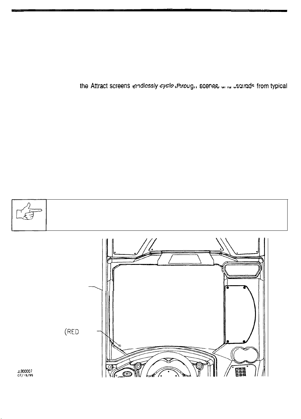
three consecutive games, it activates a visual signal. The signal appears as a red dot in the lower left
corner of the Attract screens (refer to Alert Mode under Game Operation on the following page). This
alerts the operator or attendant that the game performance is compromised. The fault is detected well
before scheduled routine maintenance occurs.
When the alert signal is seen, the operator must discover what error condition has been detected. After
players have finished racing, unlock and open the coin door. Press and hold the TEST button to enter the
Menu System. Select each test in order and activate it. One of the tests will find the error and display it.
When the error condition is resolved, the computer self-test routine detects that the game is again fully
functional. The visual signal is removed from the screen to prevent false alerts.
PLAYER STATISTICS
This game stores individual data for registered team members on the hard disk drive. The information is
duplicated on the hard disk drive of every linked cabinet. When a disk drive is replaced, the files will be
duplicated on the new disk drive only after a team member plays a game on this cabinet. These redundant
files prevent data loss and increase game reliability. The maximum number of stored records is 1024.
2-4
Page 17
GAME OPERATION
INITIAL START UP
Switch ON power to the game. Automatic self-diagnostic tests verify and report the condition of the hard
disk drive, memory, controls, etc. Messages display while the software is loading. Error messages remain
until the ABORT button is pressed. If there are no errors, the game enters Attract Mode automatically.
NOTE: When faults are detected, the game halts and an error message may appear on the screen.
Record any messages before attempting to service the game. Press ABORT to clear messages.
Before the game starts, ihe AtiiXi
SCEXCS =:I wvzaauy u,utu &I llvu
nn~n e @l~ ~ w 4n t hrnl tghIacmxw ac a n d sn t m dc fr o% !ygi c a !
uvvl Ivv .., I- vvIII~v
games. Insert the desired amount of coins or tokens and press the GAS pedal to begin game play.
ATTRACT MODE
Before the game starts, the Attract screens show scenes and sounds from typical games. The attraction
screens cycle endlessly until a player starts the game. Players may preview the game before starting.
During the Attract Mode, an advertisement periodically appears regarding contests and promotions. When
the time limits for these events expire the details will disappear from the display (refer to Game Options).
ALERT MODE
The Operator Alert Signal will appear at the lower left corner of the Attract screens if the computer veriiies
a fault. When the cause has been corrected, the indicator automatically disappears from the screen
TEST MODE
The operator may enter the menu system at any time to analyze the game or adjust it if required.
NOTICE: Do not open the coin door and enter the Test Mode while games are linked.
This may halt games in progress on other cabinets.
LEFT SIDE OF CABINET
(RED
ALERT SIGNAL
X300007
07/19/99
DOT)
LOCATION OF OPERATOR ALERT SIGNAL
2-5
Page 18
PLAYER CONTROLS
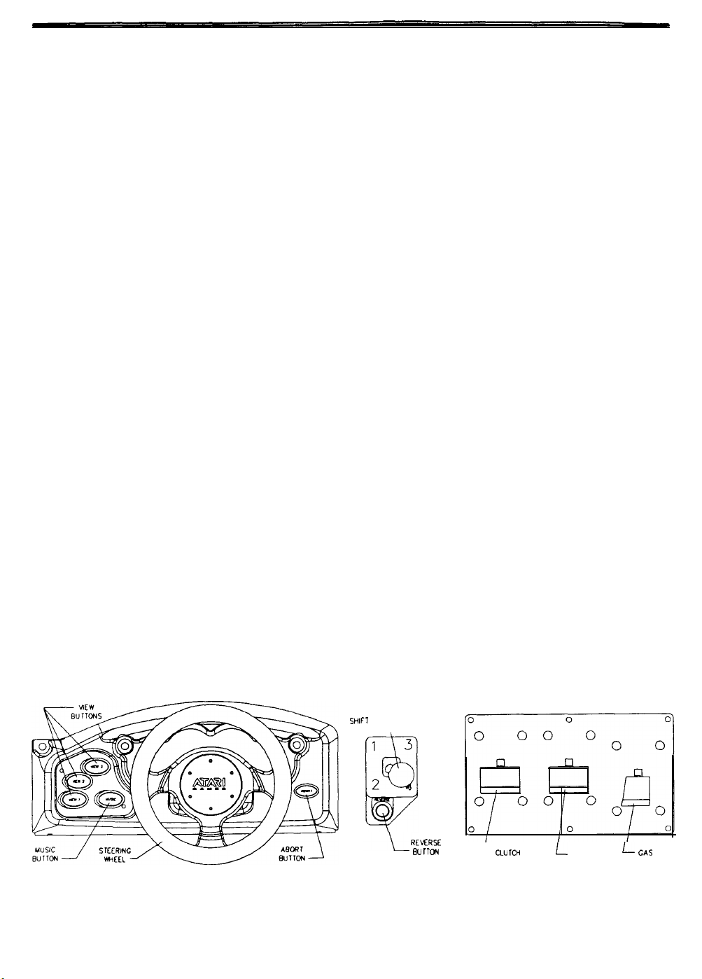
Player controls allow a driver to pilot the cars around the track. These controls mimic those found in a real
car. Many of these controls are also used when setting up a custom car or entering player information.
VIEW 1 button permits players to see the course from the front of the car during the race.
VIEW 2 button allows players to see the roadway from inside the car (normal driver viewpoint),
VIEW 3 button gives the player an aerial view. Players see the whole area from above and behind the car.
MUSIC changes the tune volume during a race. Tap this button to change loudness or to turn sounds off.
ABORT button resumes immediate game play. The car lands back in the middle of the selected track.
REVERSE button changes the direction of wheel rotation. Press this button to back up the vehicle.
GEARSHIFT selects the best gear for acceleration, cruising, or deceleration (manual transmission only).
SEAT ADJUSTER pulls to the left to change seat position. Release the lever and rock the seat to lock it.
REAR VIEW MIRROR allows the driver to see who is behind him. The mirror cannot be adjusted.
LEADER LIGHT illuminates when the driver passes all other cars on the track. It indicates a front runner.
INFORMATION PANEL gives a brief description of the Team Rush entry procedure instructions.
KEYPAD is used to enter a new or previous registered team member’s Personal Identification Number.
GAS PEDAL controls the car acceleration. Full throttle occurs after five seconds if gas pedal is not used.
BRAKE PEDAL slows or stops the car. Heavy braking affects the players ability to steer the car quickly.
CLUTCH PEDAL permits fast gear changes. The clutch also adds distance when the car is airborne.
STEERING WHEEL aims the car during a race. The steering wheel provides road feedback to drivers.
GEAR
SH’FT
7
REMRSE
BU
rroN
L
CLU 1CH
L
BRAKE
L-
GAS
PLAYER CONTROL LOCATIONS
2-6
Page 19
OPERATOR CONTROLS
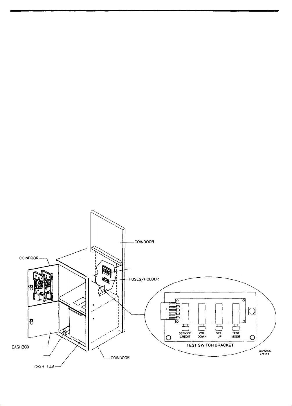
Operators have lock-and-key access to the menu system for statistics, adjustments, and testing to prevent
tampering. On-screen messages guide the operator through menu options.
The ON/OFF SWITCH is located next to line cord on the power supply. The switch is on the cabinet rear.
The MONITOR REMOTE ADJUSTMENTS are located inside the coin vault. Use the monitor test
along
with these controls to adjust the video image size, brightness, contrast, etc.
screens
The RESET SWITCH restarts the game during service. It does not change statistics or setup information.
Press RESET to observe CPU indicators during startup. RESET is on the CPU Board Assembly.
The DIP SWITCHES are used to set the hardware variables for this game. These switches are located on
the Sound I/O Board Assembly inside the electronics enclosure.
The TEST button activates the game SELF TEST menu system. Press the Test button to enter the Menu
System and select individual diagnostics, audits, utilities, and other features.
The VOLUME UP button moves up through the menu selections or adjustment items and raises the
sound level in game play. The VIEW and MUSIC buttons also move through the selections.
The VOLUME DOWN button moves down through the menu selections or adjustment items or lowers the
sound level in game play. The VIEW and MUSIC buttons also move through the selections.
The SERVICE CREDIT button allots credits without affecting the game’s bookkeeping total. Press this
button to get out of a menu selection or return to the main menu.
The PLAYER CONTROLS are also used to move through the Menu System and start or end tests.
CASHBOX DOOR
COIN METER
COINDOOR WOOD PANEL
SHOWN FOR REFERENCE
MONITOR CONTROLS
COINDOOR VAULT ASSEMBLY
OPERATOR CONTROL LOCATIONS
2-7
Page 20
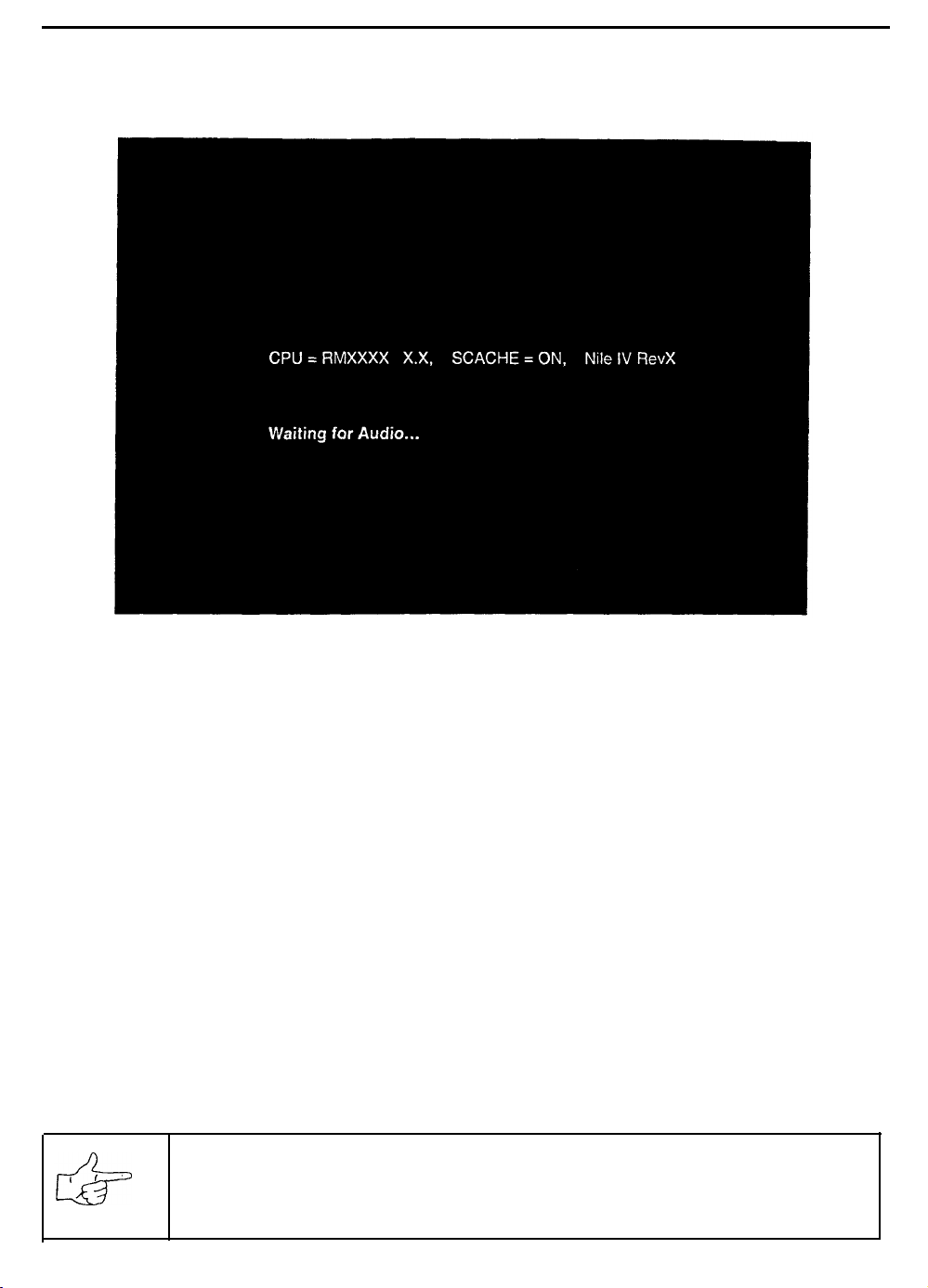
POWER-ON SELF-TESTS
The Power-On Self-Tests let the game calibrate the player controls. Don’t touch the wheel during the test.
These basic tests run automatically. They detect faults that would prevent proper game operation.
POWER-ON SELF-TESTS SCREEN
The Power-On Self-Test (POST) runs whenever you switch power off and on. The POST also runs
whenever the processor resets. The POST prevents system calibration errors to critical player controls.
A successful self-test takes less than one minute to complete. Note down messages before proceeding to
menus or game play. Players can override this screen, but may reduce performance.
After the above screen appears, the system turns the steering wheel to each of its extremes. The screen
indicates maximum and minimum position values. Dirt, debris, binding, or loose parts may cause this
routine to detect errors. The calibration routine requires less than 10 seconds.
Don’t touch the wheel or pedals during the automatic portion of this calibration routine. If the self-test has
determined that the pedals are not set correctly, on-screen messages direct you to press and release
each pedal to set travel limits. These new values will be stored in memory.
Steering wheel and pedal positions are checked for position and function. Messages appear on screen as
each item is tested, along with detected errors. Diagnose errors more thoroughly by manual testing.
ABORT.
aborting. Pressing ABORT starts the game. Yet if faults exist, players may not be able to control the cars.
During service or repair, you may need to repeatedly disconnect and restore power. Each break in power
causes these tests to rerun. After the first time, you may press ABORT to skip unwanted tests.
Use the ABORT button to cancel the POST. Allow the tests to complete at least once before
NOTICE: When the games are linked, the cabinet number error message may
appear during or after the Power-On Tests screen. Select and set a unique
cabinet number at each video game machine to eliminate this error.
2-8
Page 21
SERVICE REQUIRED TESTS
Each time the game returns to its Attract Mode the program checks the error log. If errors are found, the
Operator Alert Signal will appear at the lower left corner of the Attract screens if the computer verifies a
fault. The operator can inspect the game condition at a glance without entering the Menu System.
Once the red dot has appeared on screen, the operator must take action. Unlock and open the coin door.
Press and hold the TEST button to enter the Menu System. Test the controls, monitor, sound, disk drive,
etc. until the problem area can be determined. If the calibrate and repair routines do not resolve the
problem, refer to the Troubleshooting Chapter for assistance. Make repairs or adjustments as necessary.
When the cause has been corrected, the indicator automatically disappears from the screen.
SWITCHES AND JUMPERS
There are a number of hardware variables that can be changed to adapt the electronics to other uses.
Jumpers determine which circuit paths are active, and DIP Switches select instructions.
Switches
The CPU Board push button switch Sl is near the larger heatsink. This switch resets the processor. This
switch is used during service to restart the game without cycling the power off and on again.
There are two DIP Switch blocks (U13 and U17, near the center of the Sound
consists of eight individual switches. These switches are factory set for normal game operation.
NOTE: A/I instruction variables for this game are software selectable from the menu system. Each
DIP Switch should be set to its OFF position (Factory default) for proper game operation.
I/O Board Assembly).‘Each
Jumpers
Jumpers on the CPU Board match various system characteristics to optimize the memory circuits and
video signals. These jumpers may require adjustment to accommodate future upgrades or service.
NOTE: The circuit paths are optimized at the factory during the final board test procedure. Each
jumper should be left in its original position to avoid error messages or video sync problems.
ERRORS
The system detects errors at start up or during various diagnostic tests or operations and reports them on
the screen. Some errors, such as minor disk data faults, are automatically repaired by the system. Other
errors, such as player control calibration, are fixed by manually resetting the values in game memory. In
most cases, the game will continue to operate with reduced performance after discovering minor errors.
Always record error messages before attempting to correct any problem. The USER MESSAGES report
may store some additional temporary messages (refer to STATISTICS earlier in this section).
After recording the error messages, turn off the game’s power, wait a few minutes, then turn the power
back on again. Pay attention to the start-up screens and note any error messages during the Power On
Tests. If possible, enter the SELF TEST MENU SYSTEM and run all of tests related to where the errors
occurred. Record any new error messages and compare them to those previously recorded to determine
whether the errors are random or continuous in nature.
NOTE: Do
Games with errors may generate reduced earnings due to poor performance.
nor
ignore error messages even when the game can be forced to start and operate.
2-9
Page 22

NOTES
2-10
Page 23
SAN FRANCISCO
RUSH 2049’”
CHAPTER
PARTS
Warning
USE OF NON-ATARI PARTS OR CIRCUIT MODIFICATIONS MAY CAUSE SERIOUS INJURY OR EQUIPMENT
DAMAGE! USE ONLY ATARI AUTHORIZED PARTS.
.
For safety and reliability, substitute parts and modifications are not recommended.
l Substitute parts or modifications may void EMC directives or FCC type acceptance.
Page 24
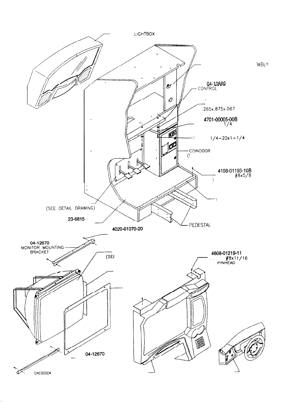
A-23188 MAIN CABINET ASSEMBLY
FRONT VIEW
PEDAL MECHANISM
MARQUEE
LIGHTBOX ASSEMBLY
(SEE DETAIL DRAWING)
INSTRUCTION LIGHT ASSE
( SEE D ETAIL DRAWING)
nA-17&W
-- - -
-CONTROL
-
PANEL BRACKET
4700-00034-00
FLAT WASHER
.265x.075x.067
4701-OoOQ5-006
LOCKWASHER
l/4
4020-01070-20
SCREW
COINDOOR ASSEMBLY
SEE DETAIL DRAWING)
1/4-20x1-1/4
4108-01193-108
SCREW
TAMPER RESISTANT
01-15069
BASE TRIM
-MBLY
SPLIT
HH
#8x5/8
J/2/99
FLOORBOARD MAT
M ONITOR MOUNTING
BRACKET
MONITOR COVER ASSEMBLY
SCREW 1/4x1-1/4 HH
VIDEO MONITOR
E DETAIL DRAWING)
08-8354
LIGHT BARRIER
03-9929
BARRIER PANEL
(SEE DETAIL DRAWING)
04-10112
- UPEDESTAL
SUPPORT BEAM
4608-01219-11
SCREW
CONTROL PANEL ASSEMBLY
(SEE DETAIL DRAWING)
#8x1 l/16
3-2
Page 25
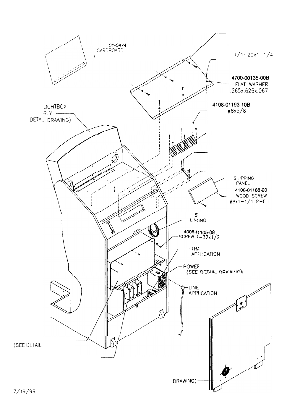
A-23188 MAIN CABINET ASSEMBLY
REAR VIEW
u,--I-r
,ARDBOARD HEADER
(FOR U.S. MODELS ONLY)
/-
01-15079
MAROUEE SUPPORT
BRACKET
4020-01100-20
SCREW
1/4-20x1 -l/4
TAMPER RESISTANT
4700-00135-008
fMT 'uVASHiR
.265x.626x.067
MAROUEE
(SEE
ASSEM
DETAll
LIGHTBOX
?IkAwINc)\
SCREW
,
j
T
-
PARTICLE BOARD SCREW
797-15276-00
<ING CABLE 16’
~110508
1-32x1,/2
\NSFORMER (SEE
‘LIGATION
?
SUPPLY ASSEMBLY
rlC T AI I
4108-01193-109
#8x5/8
TAMPER RESISTANT
01-13996
LOUVERED VENT
4108-01188-208
#8x1-1/2 FLH
20-9267
HANDLE
P-PH SEMS
CHART)
nn. ,. ., ., rr \
TRX
ELECTRONICS ASSEMBLY
(SEE
DETAIL DRAWING)
PEDAL MECHANISM
( SEE DETAIL DRAWING)
GNC00005
7/l 9/99
CORD (SEE
JCATION CHART)
-
REAR DOOR ASSMBLY
(SEE DE T AIL
DRAWING)-
3-3
Page 26
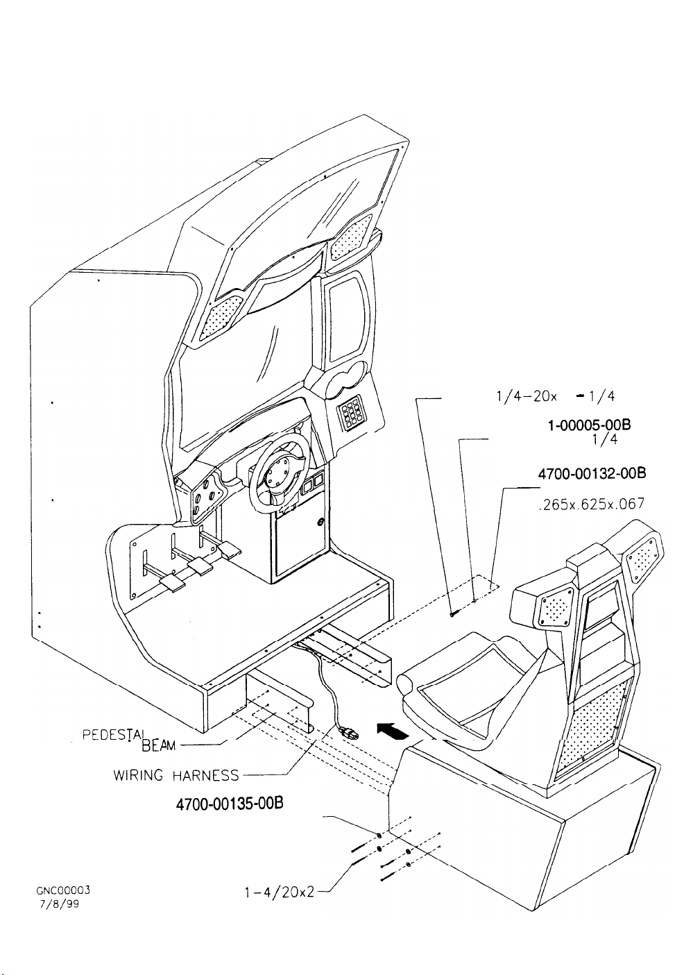
CABINET AND PEDESTAL ASSEMBLY
FRONT VIEW
4020-01070-20
SCREW
1,/4-20x
LOCKWASHER
470
1 -
l/4
1-00005-006
l/4
HH
SPLIT
S UPPORT
WIR
BEP
llNG
4700-00135-OOB
FLAT WASHER-----
.265x.626x.067
r--
4700-00132-008
FLAT WASHER
.265x.625x.067
GNCQ0003
7/a/99
4020-01100-32
:APSCREW
TAMPER RESISTANT
1-4/20x2-
3-4
Page 27
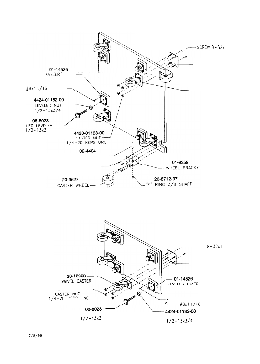
CASTER AND LEVELER ASSEMBLIES
BOTTOM VIEW
4608-01219-11
SCREW
#8x1
1/2-13x3
LEVELER PLATE
l/16
PINHEAD
CASTER SHAFT
WOOD SCREW
,,/---SCREW
4008-01113-16
8-32x1
04-10633
SWIVEL MOUNTING BRACKET
20-10360
SWIVEL CASTER
PC-HWH
GNC00006
7/a/99
BOTTOM VIEW OF CABINET ASSEMBLY
4420-01128-00
l/4-20
KEPS
U
LEG LEVELER
1/2-13x3
BOTTOM VIEW OF SEAT ASEMBLY
-SCREW
SWIVEL MOUNTING BRACKET
4608-01219-11
CREW #8x1
l/16
4424-01182-00
LEVELER NUT
1/2-13x3/4
4008-01113-16
8-32x1
PL-HWH
04-10633
PINHEAD
3-5
Page 28
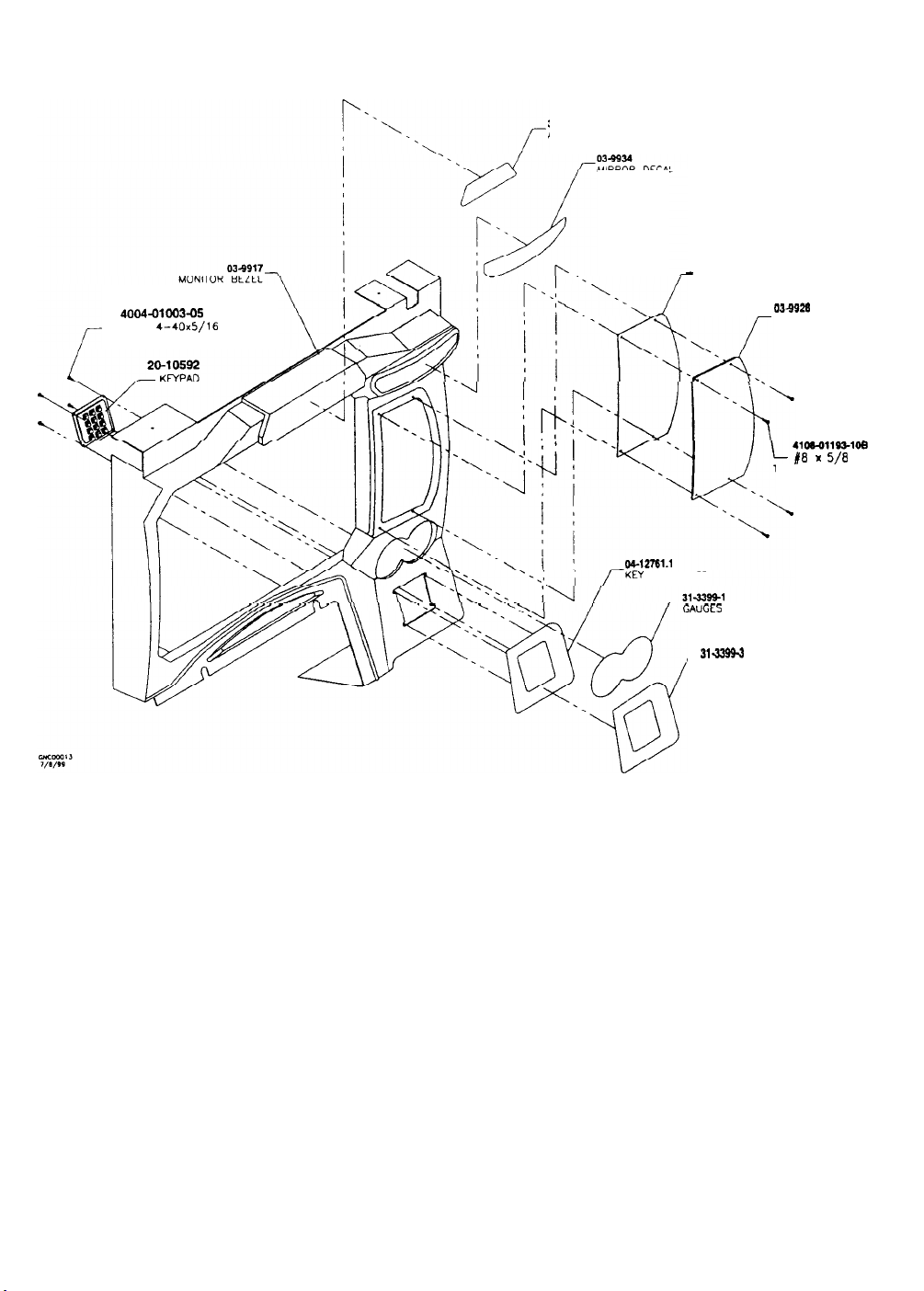
A-23191 MONITOR COVER ASSEMBLY
FRONT VIEW
315399-z
ATARI GAMES DECAL
MIRROR DECAL
315397.1
-
DECAL. BEZEL
4004-0100305
SCREW
4-40x5/16
P-PH-S
UEY
PAD PLATE
GAUGES
DECAL
31-3399-3
-KM PAD DECAL
03-9920
INSTRUCTIONS PANEL
41oEo11931oB
#0 1
5/0
TAMPER RESISTANT
3-6
Page 29
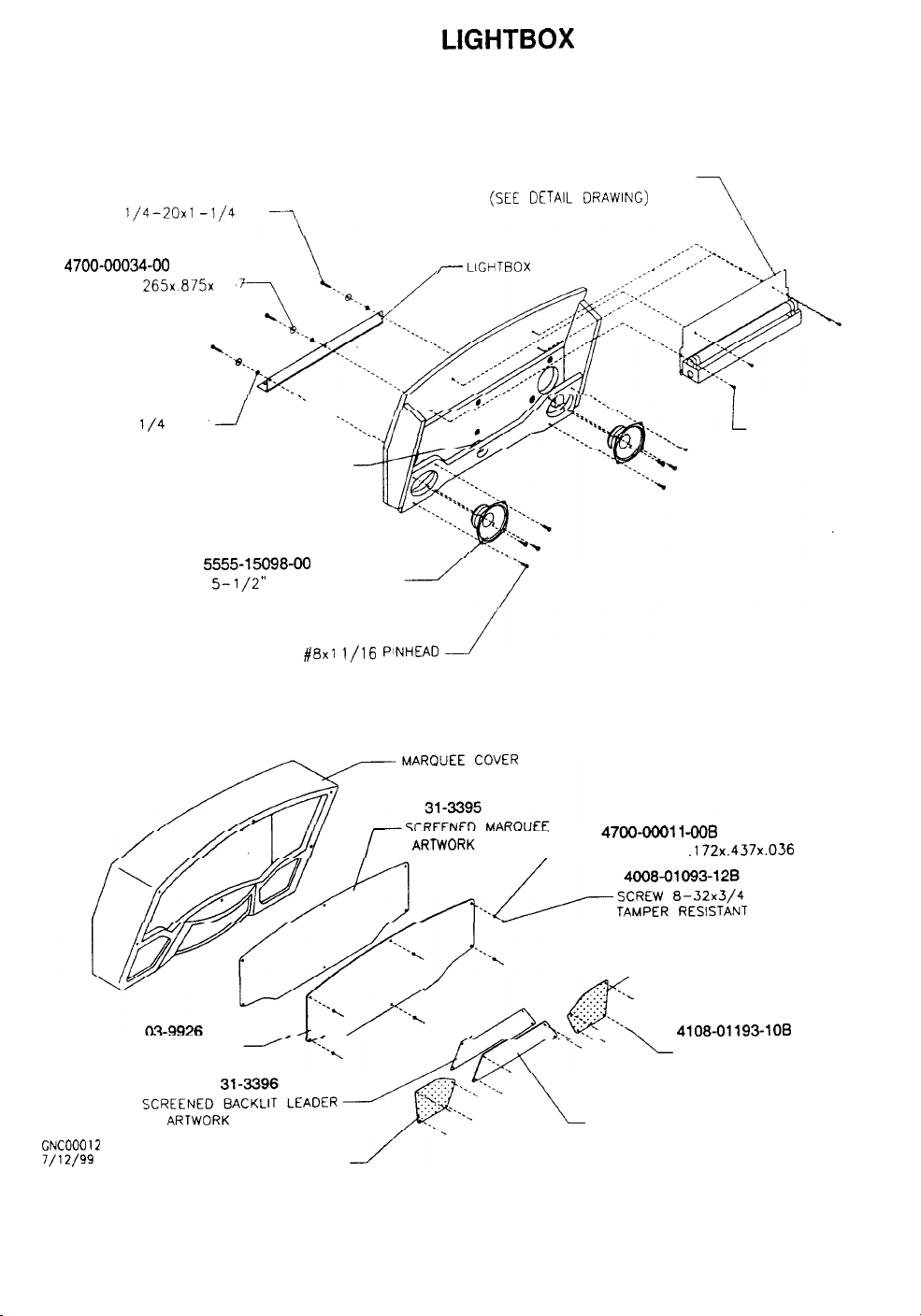
A-231 89 MARQUEE LIGHTBOX ASSEMBLY
FRONT VIEW
4020-01070-20
SCREW
4700-00034-00
FLAT WASHER 265x.875x 06
4701-00005-00
LOCKWASHER
1/4-20x1 -l/4
l/4
SPLIT
LEADER LIGHT ASSEMBLY
(SEE DETAIL DRAWING)
5555-15098-00
SPEAKER,
5-l/2”
HH
\
-.
--- . . . . .._____
8 OHM SHIELDED
4608-01219-11
SCREW #8x1
l/16 PINHEAD
FLUORESCENT LAMP ASSEMBLY
(SEE
DETAIL DRAWING)
20-10560
/- LIGHTBOX HINGE
4008-01113-06
SCREW 8-32x3/8
PL-HWH
GNC00012
MAROUEE PANEL
01-15065
SPEAKER GRILL
03-9916
’
//-J+g;,
47oo-m,, -OOB
-FLAT WASHER .172x.437x.036
01-15065
,-SPEAKER GRILL
4108-01193-106
L
SCREW
TAMPER RESISTANT
03-9927
LEADER PANEL
#8x5/8
3-7
Page 30
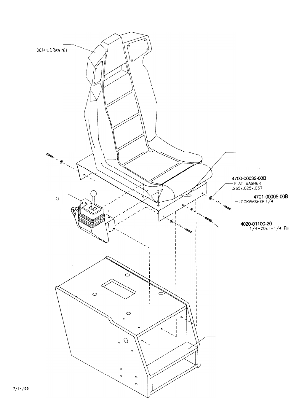
SEAT ASSEMBLY
(SEE
DETAIL DRAWIN
A-23199 SEAT PEDESTAL
FRONT VIEW
ASSEMBLY
SEAT SLIDE ASSEMBLY
( SEE DETAIL DR AWIN G)
SHIFTER ASSEMBLY
(SEE DETAIL DRAWING)
-
,,,,
/’ ,’
.
-CAPSCREW
04-12676
PEDESTAL ASSEMBLY
4701-00005-008
LOCKWASHER
4020-01100-20
TAMPER RESISTANT
l/4
1/4-20x1-1/4
SPLIT
BH
GNC00019
T/14/99
3-8
Page 31
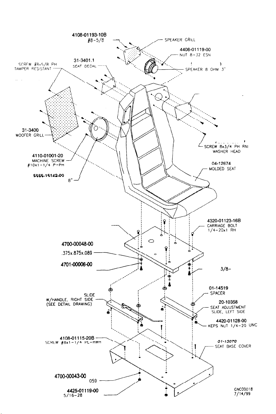
A-23200 SEAT ASSEMBLY
FRONT VIEW
4108-01193-108
----
.- --
SPEAKER WOOFER
4108-01193-108
SCREW
TAMPER RESISTANT
--
a--J
/E-S/S
PH
04-12815
-
5555-16234-00
01-14497
,r-
SPEAKER PORT GRILL
4208-01203-12
01-14495.1
SEAT BASE PANEL
4700-00048ao
FLAT WASHER
.375x.875x.089
47Ol-Oooo6-00
LOCKWASHER 3/a SPLIT
SEAT ADJUSTMENT
FLAT WASHER 328x.562x
4700-00043-00
4425-01119-
NUT
5/16-28
ESN UNC
SLIDE
4322-01070-12
SCREW
3/8-
16x3/4
HEX HEAD
0%
CNCOOOlB
7/l 4/99
3-9
Page 32
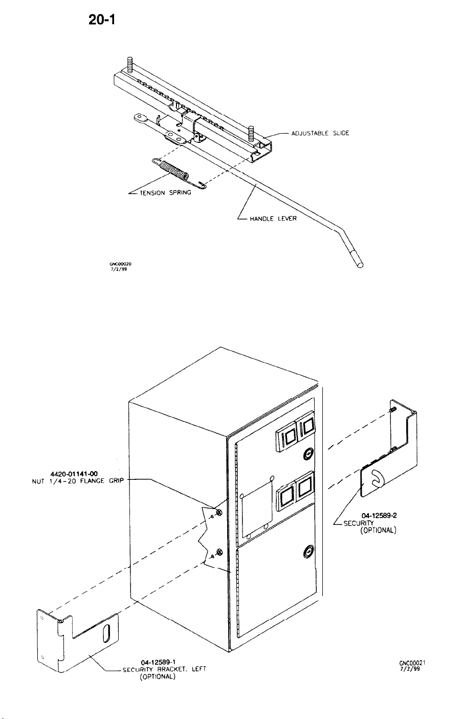
20-l 0357 SEAT ADJUSTER WITH HANDLE
FRONT VIEW
OPTIONAL COIN BOX SECURITY BRACKETS
FRONT VIEW
P
__I
3-10
0
0
8
/
/
/
/
04-12589-2
SECIJRIM BRACKET. RIGHT
(OPTIONAL)
GNC00021
T/2/99
Page 33
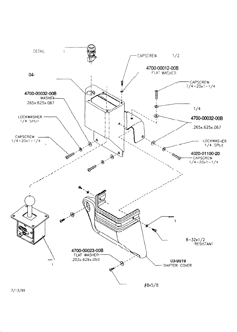
PUSH BUTTON, WHITE
DETAIL DRAWING) 4008-01100-08
(SEE
04-
12675
SHIFTER HOUSING
4700~00032-008
FLAT WASHE
.265x.625x.067
4701-00005-006
4020-01100-20
TAMPER RESISTANT
A-23202 SHIFTER ASSEMBLY
FRONT VIEW
CAPSCREW 8-32x
TAMPER RESISTANT
I
I
I
/
/
4700~00012-OOB
- FMT \*,ncLlcP
187x.375x.040
.vrli\ ICI\
l/2
4020-01100-20
7
CAPSCREW
1/4-20x1 -l/4
TAMPER RESISTANT
4701-00005-008
LOCKWASHER
l/4
SPLIT
4700-00032-006
FLAT WASHER
.265x.625x.067
4701-00005-008
-iER
.IT
/’
/
/
/
I-,’
4-SPEED SHIFTER
(SEE DETAIL DRAWING)
GNC00022
7/l 3/99
‘\
/
,’
. .
/’
/’
/’
TAMPER RESISTANT
‘-,
,/’
4700-00012-008
-
FLAT WASHER
i 87x.375x.040
4008-01093-08
SCREW
8-32x1/2
TAMPER
PH
RESlSTANl
4700-00023-OOB
4108-01193-I OB
SCREW
#8x5/8
TAMPER RESISTANT
PH
3-11
Page 34
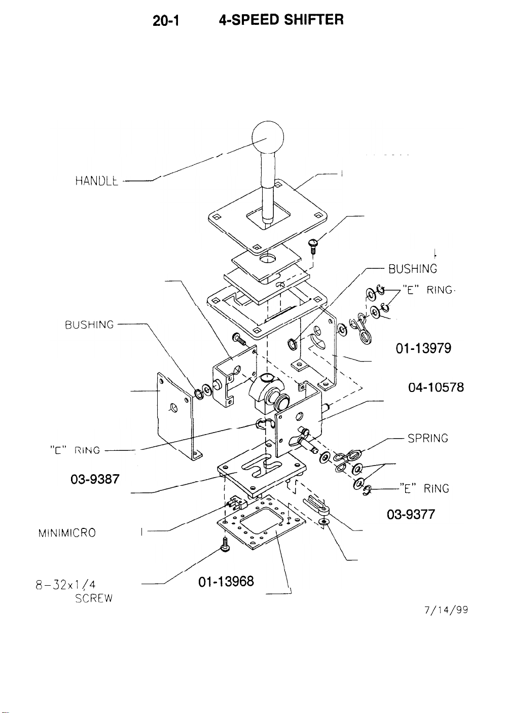
HANtILt d
04-10577
SIDE PLATE, RIGHT
20-l 0369 4-SPEED SHIFl-ER
FRONT VIEW
31-2611
INDICATOR PLATE
4008-01003-04
8-32x1/4 P-PH
SEMS SCREW
02-5284
02-5284
01-13969
SIDE PLATE, REAR
GATE BLOCK
5647-14574-00
MINIMICRO SWITCH
4008-01003-04
8-32x1
SEMS
/4 P-PH
Si)REW
BACK PLATE
FLAT WASHER
SIDE PLATE, FRONT
SIDE PLATE, LEFT
10-514
FLAT WASHER
SWITCH ACTUATOR
FLAT WASHER
-
GNC00023
7/14/99
3-12
Page 35
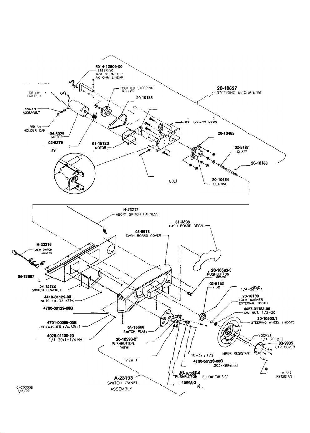
A-23192 DASH ASSEMBLY
FRONT VIEW
CONTROL PANE
\ 1,
TOOTHED DRIVE
PULL
REAR VIEW
--..‘.-.I
BRACKET
‘.\
--/
// ‘24.
20-10166
r---
TOOTHED BELT
TENSION BRACKET
BELT TENSION
ADJUST
EOLT
/
4410-01126-00
PuSHBUllON. RED
BEARING
29-10693-6
HOUSING
20-10163
SHAFT
4026-01191-166
SOCKET HEAO BOLT
/
KEY
CNCWOO8
J/8/99
47Oo-OO129-aoB
FIAT WASHER
2651625x.067
47Olam6QOB
I
m-YW.C"FT) ,,4 <PI IT
402O-Ollm-20
SCREW
1/4-20x1-1/4 BH
TAMPER RESISTANT
20-10693-2
PUSHBUTlON.
PUSHBUTTON, BLUE
ASSEMBLY
BLUE
-VIEW
2’
20-10593-l
-
3-13
4010-01100-06
lo-32 x l/2
I-PM .-.m.aa n-WWUUIL~B
l-
FLAT WASHER .203x 466x 030
II
M
. . .
..?#.a
N,Vil-
PUSHBUl-TON.
C10693-3
__--
2a
PUSHBUTTON.
/
a
ELLOW
Y
-
JE -VIEW 3”
BLl
TA
‘MuSIC-
4020.0107416
+OCKET
l/4-20 I( 1
4006-01100-06
2
IO-32 I
TAMPER RESISTAN
HEAD BOLT
l/2
Page 36
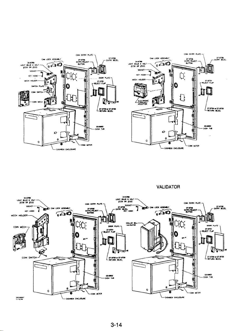
COIN DOOR ASSEMBLIES
(REFER TO APPLICATION CHART FOR PART NUMBERS
ELECTRO-MECHANICAL COIN DOOR ASSEMBLY
ELECTRONIC COIN DOOR ASSEMBLY
ALTERNATE ELECTRO-MECHANICAL ASSEMBLY
DOLLAR BIL
VALIDATOR DOOR ASSEMBLY
Page 37
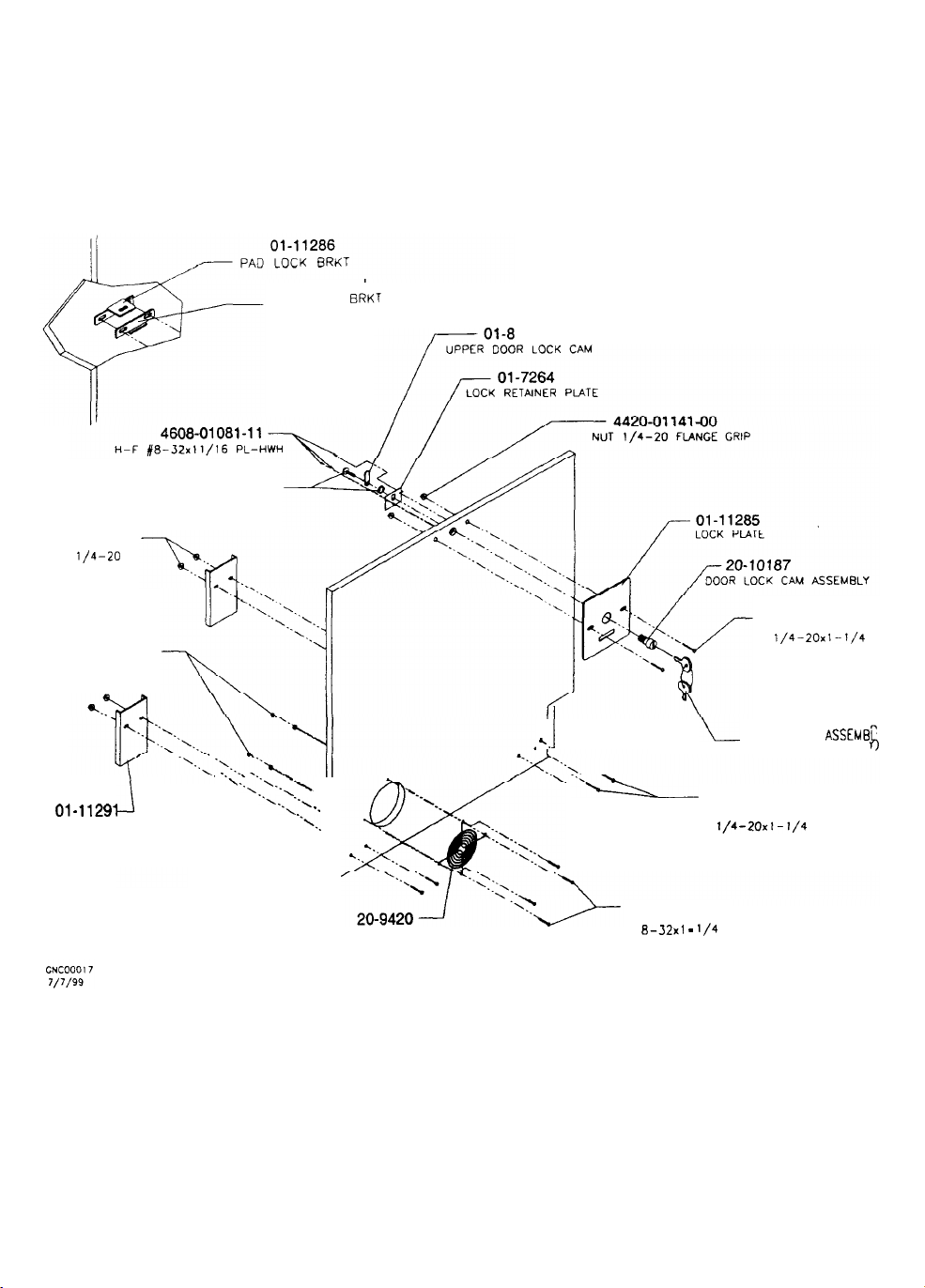
(PART OF DOOR CAM LOCK ASSEMBLY)
4420-01141-00
NUT
l/4-20
FLANGE GRIP
A-23196 REAR DOOR ASSEMBLY
REAR VIEW
01-11287
KEY LOCK
BRKT
989
4408-01128-00
NUT 8-32 KEPS
01.
.11291
BRACKET
DOOR
“\ ‘A
‘.\
“\
“1
“,
“1
“1..
-.
I
FAN GUARD 4”
4320-01123-208
CARRIAGE BOLT
1/4-20x1-1/4
KEYS (PART OF 000
*.
I
-‘--
4308-01123-20
8-32x1
4320-01123-208
CARRIAGE BOLT
-
l/4
CAM LOCK ASSEMEL
CARRIAGE BOLT
1/4-20x1-1/4
3-15
Page 38
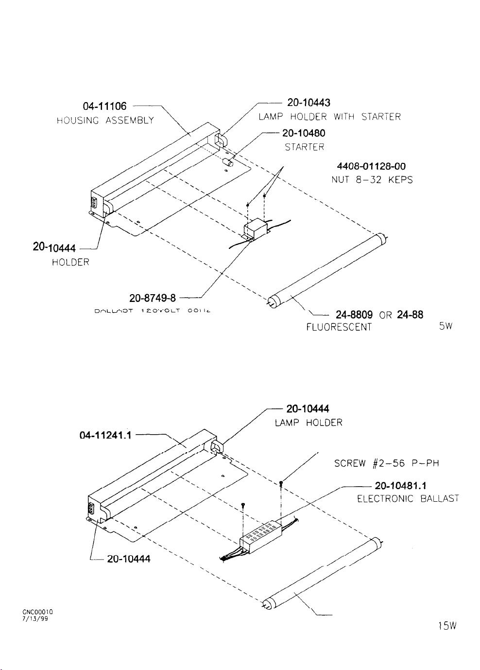
FLUORESCENT LAMP ASSEMBLIES
FRONT VIEW
A-22365
20-
LAMP
FLUORESCENT LAMP ASSEMBLY (U.S./CANADA)
74
FLUORESC:ENT
BULB 18” 1
A-22506
FLUORESCENT HOUSING
LAMP HOLDER
GNCOOOIO
7/l 3/99
FLUORESCENT LAMP ASSEMBLY (UNIVERSAL)
4002-01105-04
24-8809
FLUORESCENT BULB 18” l5W
3-16
OR
24-8874
Page 39
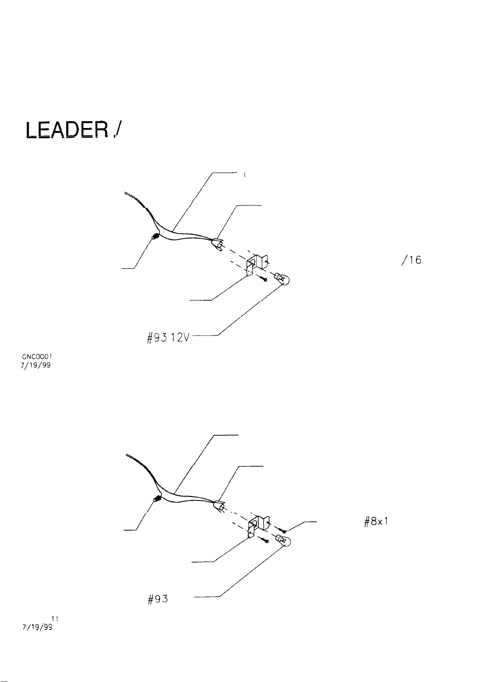
INCANDESCENT LAMP ASSEMBLIES
FRONT VIEW
A-231 90
LEADER
5822-15270-00
WIRE CONNECTOR
01-15064
LEADER LIGHT BRACKET
LIGHT BULB
GNCOOOl 1
7/ 19/99
/ INSTRUCTION LIGHT ASSEMBLY
-. ~~ ~~~~
LIGHT HARNESS
24-8870
LIGHT SOCKET
4608-01219-11
/16
1 1 PINHEAD
-,-SCREW
24-8862
#93 12V
#8x
WIRE CONNECTOR
LEADER LIGHT BRACKET
LIGHT BULB
GNCOOO
11
7/ 19/99
#93
12V
LIGHT HARNESS
LIGHT SOCKET
3-17
SCREW
#8x1
l/l 6 PINHEAD
Page 40
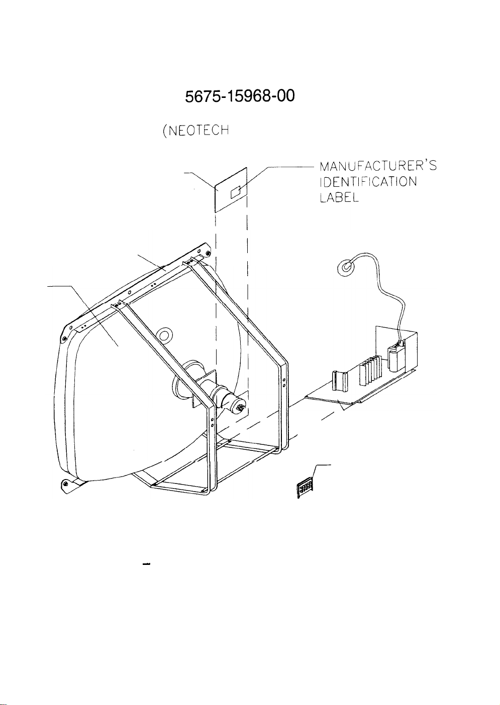
CRT
*NECK BOARD
FRAME----,
VIDEO MONITOR ASSEMBLY
REAR VIEW
5675-l 5968-00
VIDEO MONITOR
(NEOTECH
NT-2702)
,
’
-*MAIN
/
REMOTE ADJUSTMENT
BOARD ASSEMBLY
*THESE PARTS ARE AVAILABLE ONLY AS
-
A SET
ORDER PART NO. 04-12785
3-18
BOARD
ASSEMBLY
Page 41
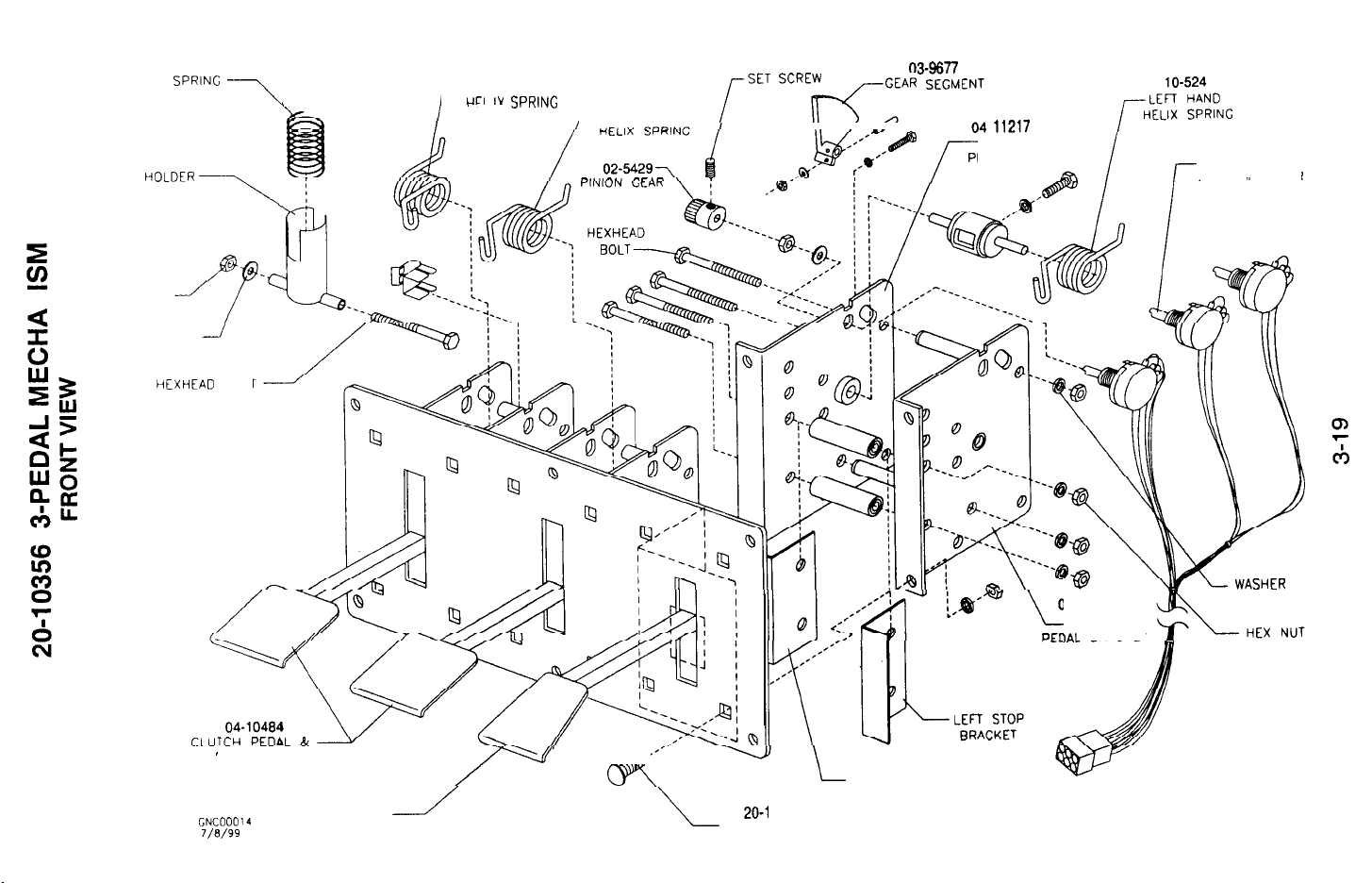
Z
COMPRESSION
SPR’NG
SPRING
HoLDER
e-f’,,
NUT
HEX
FLAT WASHER
HEXHEAD BOLT
1 O-525
\
\,
--/
RIGHT HAND
I---
UCI IV SC”I,NG
1 C-524
,--LEFT HAND
iSET
scREf-q-,,,
03-9677
-1
D
/-
,,2,7
RIGHT
PEDAL BRACKET
I
14-11216
-LEFT
IAl RRACKET
5014-15453-00
POTENTIOMETER
5K OHM LINEAR
I-
BRAKE PEDAL
GNCLlOOl4
?/E/99
04-10483
GAS PEDAL
/==af
/
/
-A’
20-I
0573
CARRIAGE BOLT
RIGHT STOP
BRACKET
Page 42
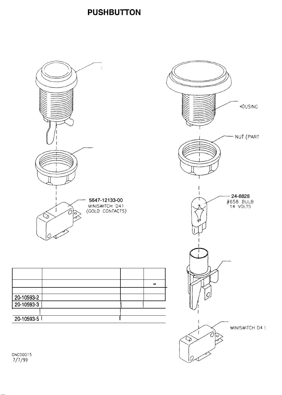
PUSHBUlTON ASSEMBLIES
(REFER TO APPLICATION CHART FOR PART NUMBERS
ROUND PUSHBUTTON OVAL ILLUMINATED
(REVERSE GEAR) (DASH BOARD)
SWITCH
HOUSING
NUT (PART OF
ASSEMBLY)
SWITCH
iOUSING
-NUT
ASSEMBLY)
(PART OF
PART
NUMBER
20-10208-2 ROUND PUSHBUTTON
20-10593-l OVAL ILLUMINATED PUSHBUTTON
20-10593-2 OVAL ILLUMINATED PUSHBUTTON
20-10593-3 1 OVAL ILLUMINATED PUSHBUTTON 1 BLUE
(
20-10593-b
20-10593-5 1
OVAL ILLUMINATED PUSHBUTTON 1 YELLOW 1 MUSIC
OVAL ILLUMINATED PUSHBUTTON1RED
DESCRIPTION COLOR
WHITE
BLUE VIEW 1
BLUE
LEGEND
-
VIEW 2
(
VIEW 3
1
ABORT
I
LAMP HOLDER
0
“-
5647-l 2133-00
MINISWITCH
(GOLD CONTACTS)
04 1
GNCOOOl5
7/7/99
3-20
Page 43
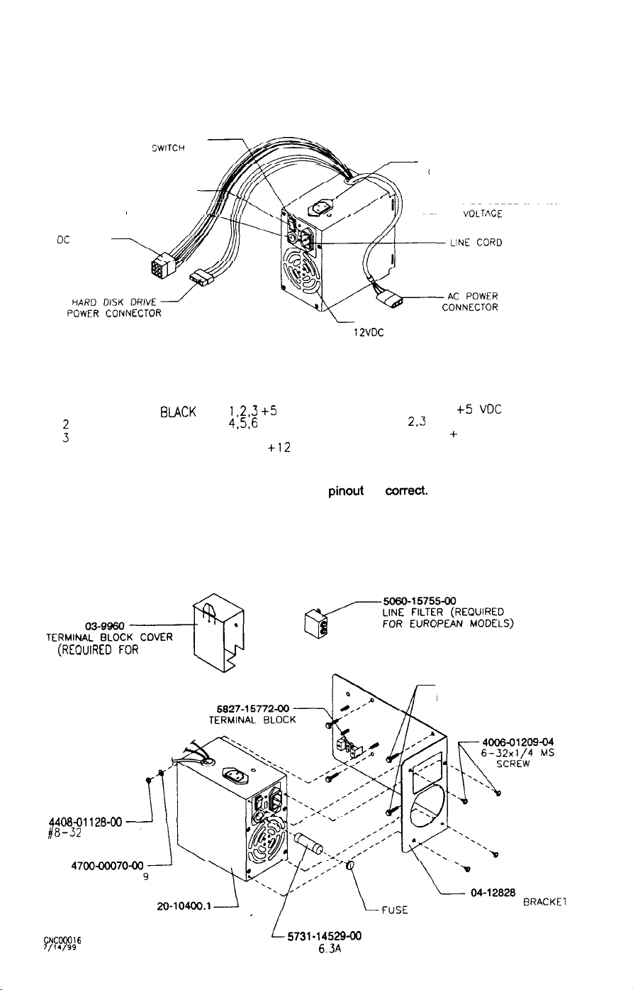
OC POWER
CONNECTOR
POWER SUPPLY COMPONENTS
FRONT VIEW
SWITCHING POWER SUPPLY
LINE VOLTAGE
k
POWER SWITCH
LINE FUSE--..
-+j
L
INTERNAL
12VDC
7
AUXILIARY POWER
CONNECTOR
CONNECTOR
FAN
ADJUSTMENT
A.C. AUXILIARY POWER
CONNECTOR
PINS FUNCTION COLOR
1
LINE BLACK
GROUND GREEN
NEUTRAL WHITE
NOTE: Many computer grade power supplies use alternate wire colors.
This is acceptable as long as the
POWER SUPPLY ASSEMBLY
(REouIRED
EUROPEAN MODELS)
FOR
D.C. MAIN POWER
CONNECTOR
PINS FUNCTION COLOR
1,2,3 +5
4,5,6
VDC RED
RETURN BLACK
7
-5 VDC BLUE
+12
8
9 -12 VDC WHITE
VDC YELLOW
pinout is CotTaCt.
HARD DISK DRIVE POWER
CONNECTOR
PINS FUNCTION COLOR
1
+5
VDC
RETURN BLACK
2.3
+ 12 VDC YELLOW
4
460801081-l 1
#8x11/16 H-F SCREW
RED
4408-01128-00
#8-32
KEPS NUT
4700-ooo70-00
187x.625x.05
FLAT WASHER
WC00016
7/14/99
POWER SUPPLY ASSEMBLY
5731-14529-00
FUSE 6.3A 250V
3-21
HOLDER CAP
POWER
SUPPLY BRACKEl
Page 44
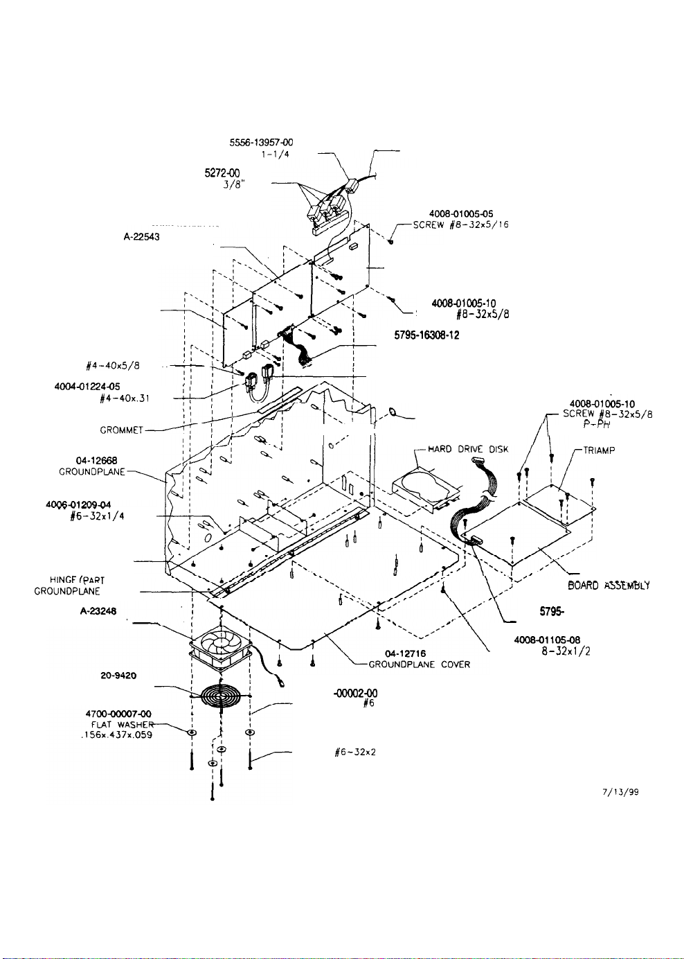
A-23194 ELECTRONICS ASSEMBLY
FRONT VIEW
A-225‘G
CPU BOARD ASSEMBLY
20-10565
VIDEO BOARD
ASSEMBLY
4004-01005-10
SCREW
JACKSCREW #4-40x.31 2 SH
SCREW
W/SPRING SEMS
#4-40x5/a
4m4-01224~5
RM-37-11
FLEXIBLE
04-12668
GROUNDPLANE\
.__ _.-__ _.
#6-32x1/4
P-PH ’
GROMMET/
P-PH
55.s13957ac
FERRITE BEAD
5556-l 5272-00
FERRITE BEAD
I ’ I ‘“-‘?‘I .
I/,
3/8”
SPLI T
l-1/4
x3/4
! SHIELDED VIDEO CABLE
H-23210 2
MAIN HARNESS ASSEMBLY
,iscRcw
-SOUND I/O BOARD ASSEMBLY
RIBBON CABLE. 40-PIN 12”
4008-01005~5
#a-32d/16
A-23255
4008-01005-10
SCREW #a-32x5/a P-PH
5795-16308-12
m-10493
m-10599
SPLIT GROMMET
__.--
A-231 95
P - PH
r
/I
scREw
4008~1&5-10
#a-32x5/a
cl
“L,
r-m
04-12769.1
TRIAMP
ASSEMBLY
f
BOARD
4408-01128-00
NUT #a-32 KEPS
HINGE (PART OF
GROUNDPANE
FAN ASSEMBLY
FAN GUARD 4”
ASS’Y)
---lw
4701
moo2-00
LOCKWASHER #6 SPLIT
4006-01113-32
SCREW
#6-32x2 PL-HWH
3-22
74’
RIBBON CABLE.
4008-01105-08
-SCREW
P-PH SEMS
r.n.mm
~“AKLJ A3,tMDCT
5795-
10937
8-32x1/2
04-12770.1
WHEEL DRIVER
.rCr.,n,
-18
20-PIN
CNC00009
7/13/99
.I
Page 45
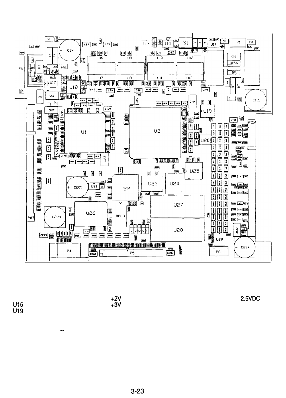
A-22543 CPU BOARD ASSEMBLY
Field Replaceable Parts
DESIGNATION
u5
u15 5460-l 5671-00 +3V Regulator Voltage Regulator 3.3 VDC
u19
u22
U27 A-5343-30036-1
U28
PART NUMBER FUNCTION DESCRIPTION
5250-l 6015-00 +2V Regulator Voltage Regulator 2.5VDC
A-2331 5
A-2291 2
_-
Bus Controller Configuration Programmed Logic Device
CPU Configuration Programmed Logic Device
CPU Boot ROM EPROM Assembly
CPU Expansion ROM
EPROM Assembly (empty)
3-23
Page 46
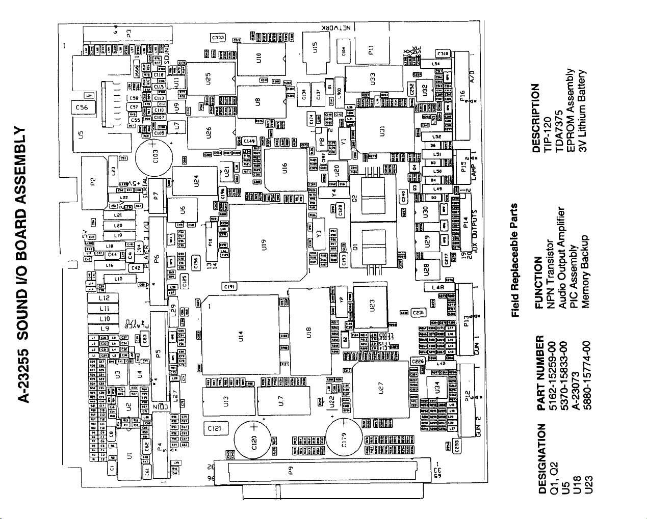
L
I
J
Page 47
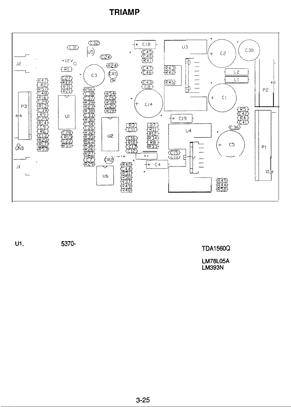
04-12769.1 TRIAMP BOARD ASSEMBLY
10 a
DESIGNATION PART NUMBER
5370-
Ul,
u3
u4
u5
U6
u2
15163-00
5370-l 5984-00
5370-l 5833-00
5250-I 3302-00
5370-l 6254-00
Field Replaceable Parts
FUNCTION
Audio Amplifier
Audio Output Amplifier
Audio Output Amplifier
Voltage Regulator
Comparator
DESCRIPTION
LM3403
TDAl560Q
TDA7375
LM78L05A
LM393N
3-25
Page 48
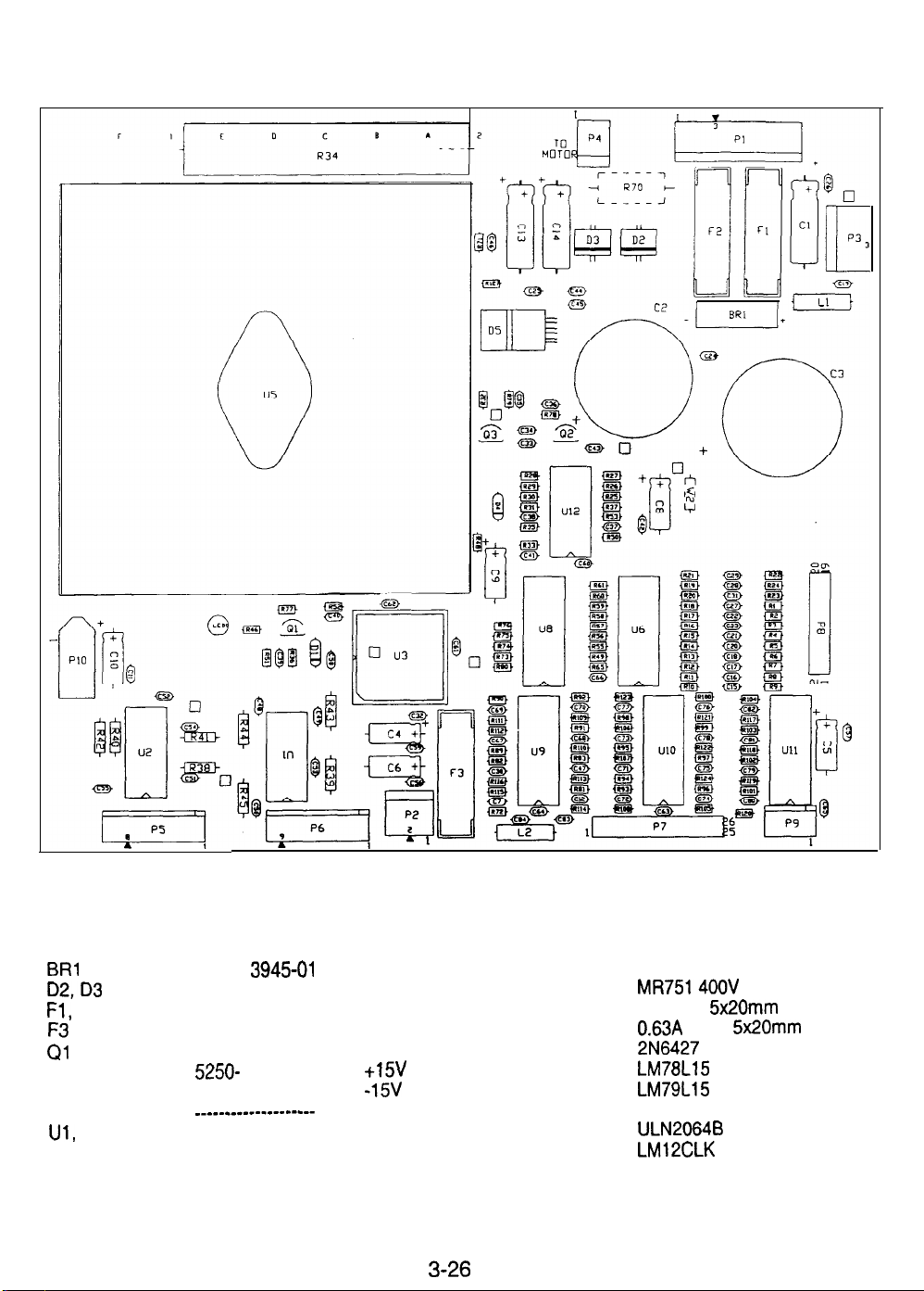
04-12769.1 WHEEL DRIVER BOARD ASSEMBLY
DESIGNATION PART NUMBER
BRl
D2,D3
Fl, F2
2
Q2
Q3
Q4
Ul,
u2
u5
5100-l
3945-01
5070-l 4526-00
5731-l 4094-00
5731-l 5627-00
5162-08976-00
5250-
15624-00
5250-l 5625-00
_____-_-m---m-------
5370-l 2602-00
5370-l 4069-00
Field Replaceable Parts
FUNCTION DESCRIPTION
Bridge Rectifier
Power Diode
Slow Blow Fuse
Fast Blow Fuse
Darlington Transistor
+15V
Regulator
-15V
Regulator
None
Amplifier
Power Amplifier
4oov 6A SIP
MR7514OOV 6A
4A 125V
0.63A
2N6427 NPN
LM78Ll5
LM79L15
Not Used
ULN2064B
LM12CLK
5x20mm
250V
5x20mm
3-26
Page 49
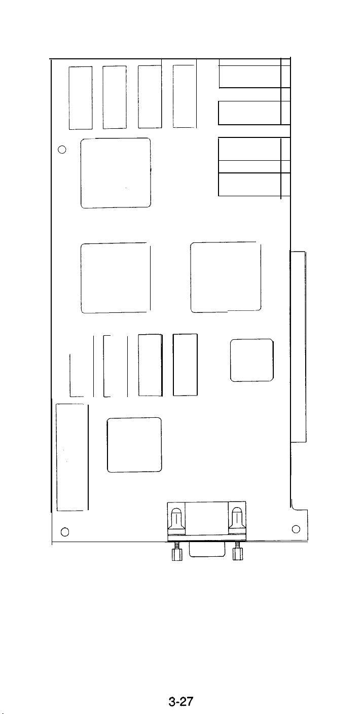
2040565 VIDEO CARD ASSEMBLY
r
1
I
L
0
Field Replaceable Parts
No field replaceable parts have been identified
3-27
Page 50
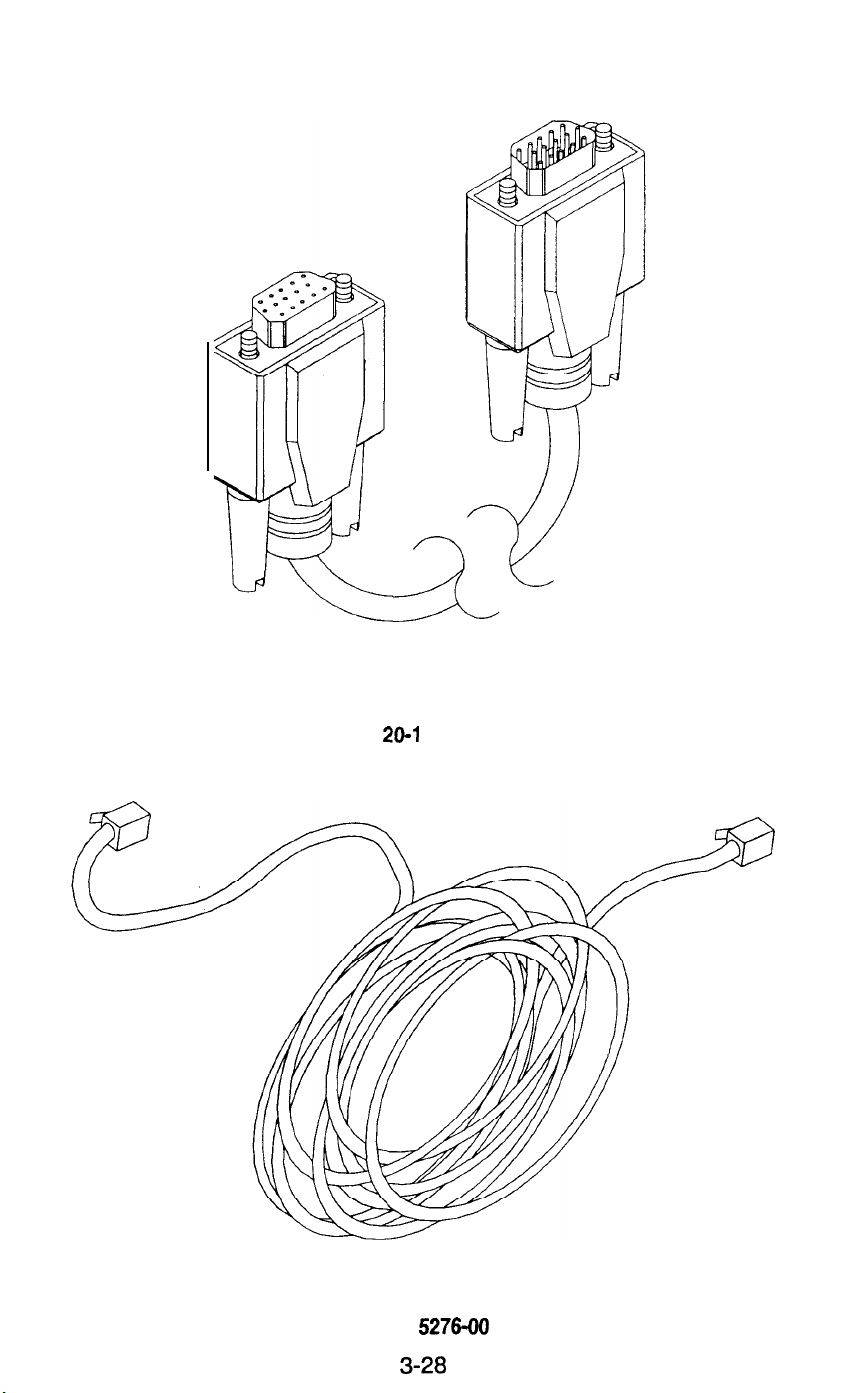
Electronic Cable Assemblies
VIDEO COMMUNICATIONS CABLE (SHIELDED DB-15F TO DB-15M)
20-l 0493
LINKING CABLE (UNSHIELDED TWISTED PAIR CATEGORY 5)
5797-l 5276-00
3-28
Page 51
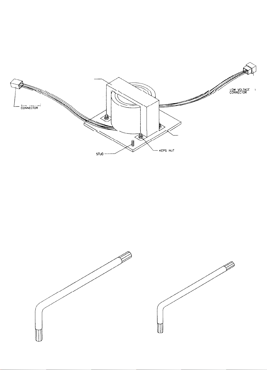
LINE VOLTAGE
TRANSFORMER ASSEMBLY
(SEE APPLICATION TABLE FOR PART NUMBER
TRANSFORMER
I
MOUNTING PLATE
GROUNO WIRE
STUD
TAMPER RESISTANT WRENCHES
(REFER TO OTHER PARTS NECESSARY)
3-29
Page 52
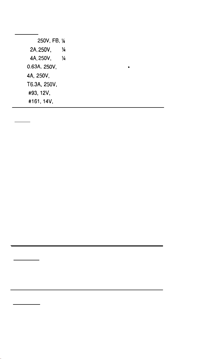
Other Parts Necessary
Protection
Fuse, 1 A,
Fuse,
Fuse,
Fuse,
Fuse,
Fuse,
Bulb,
Bulb,
Cables
AC Line Harness
AC Power Harness
Line Filter Harness
Shifter Harness
Sound Harness
Circuit Board Harness
Speaker and Light Harness
Pedestal Harness
Seat Speaker Harness
Ground Braid
Main Wiring Harness
View Switch Harness
Abort Switch Harness
Fluorescent Lamp Cable
25OV, FB, % x 1%
2A, 25OV,
4A, 25OV,
0.63A, 25OV, FB, 5 x 20 mm 573 1 - 15627-00
4A, 25OV, SB, 5 x 20 mm 5731-l 4094-00
T6.3A,
#93,
#161,
SB, % x 1%
SB,
‘/4
x 1%
25OV, 5 x 20 mm 5731-l 4529-00
12V, Incandescent 24-8862
14V, Incandescent 24-8840
5730-l 5278-00
5731-08665-00
5731-06314-00
H-22399
H-2321 1.1
H-22393
H-2321 5
H-23249
H-23230
H-2321 2
H-23213.1
H-2321 4.1
H-21 672
H-23210.1
H-2321 6
H-2321 7
H-21 492
Documents
Video Product Safety Manual
Game Information Card
Game Manual
Other Items
T-20 Tamper-Resistant Wrench
T-27 Tamper-Resistant Wrench
Crossover Coupler
16-l 0968
16-l 0650
16-30036-l 01
20-9620
20-l 0140
5796-l 5262-00
3-30
Page 53
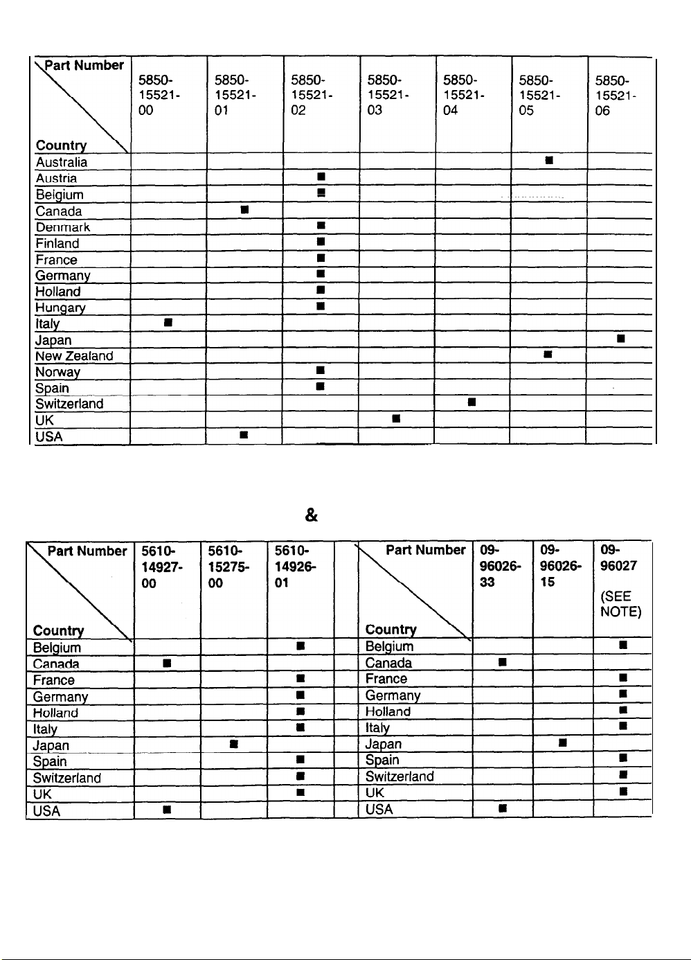
LINE CORD APPLICATION TABLE
TRANSFORMER APPLICATION & COIN DOOR APPLICATION TABLES
NOTE: These coin doors are used with 09-77000 Electronic Coin Acceptors. This device must be
programmed for the desired type of currency. Contact your authorized distributor for assistance in
programming the acceptor.
3-31
Page 54

NOTES
3-32
Page 55
SAN FRANCISCO
RUSH 2049’”
CHAPTER
FOUR
SERVICE
NOTICE
Information in this manual is subject to change without notice.
equipment function, design, or components as progress in engineering or manufacturing methods may warrant.
Fill out and mail in the Game Registration card.
cabinet. For your records, write the game serial number in the manual. SERIAL NUMBER
Include the game serial number from the label on the rear of the
Atari reserves the right to make improvements in
Page 56
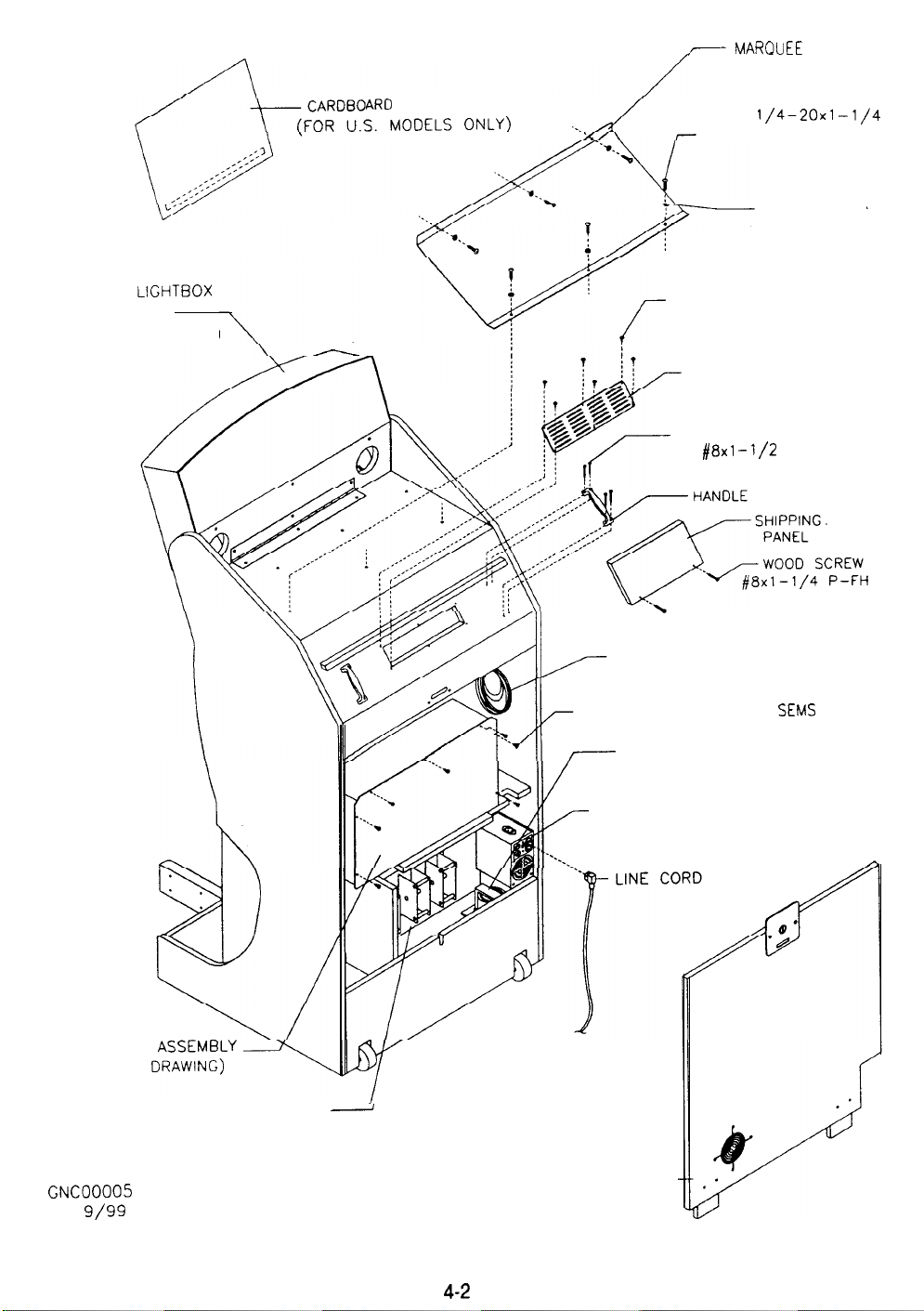
AR0 HEADER
/
,J
SCREW
TAMPER RESISTANT
01-15079
MAROUEE SUPPORT
BRACKET
1/4-20x1
FLAT WASHER
265x.626x.067
-l/4
MARQUEE
ASSEMBLY
(SEE DETAIL DRAWING)
LIGHTBOX
SCREW #8x5/8 TRX
TAMPER RESISTANT
LOUVERED VENT
PARTICLE BOARD SCREW
#8x1
-l/2
LINKING CABLE 16’
SCREW 8-32x1/2 P-PH
TRANSFORMER (SEE
APPLICATION CHART)
POWER SUPPLY ASSEMBLY
FLH
SEMS
ELECTRONICS
(SEE DETAIL
GNC00005
7/l
9/99
PEDAL MECH A NIS M
(SEE DE T AIL DRAWING)
-
REAR DOOR ASSMBLY
(SEE DETAIL DRAWING)-
4-2
Page 57
SERVICE
Only qualified service personnel should perform maintenance and repairs. The product guidelines
to all game operators and service personnel. There are specific notes, cautions, and
this manual where they apply. Read the SAFETY pages thoroughly before beginning service.
This game uses complex electronic components that are very SENSITIVE to static electricity.
Observe and follow these precautions prior to handling the game electronics:
I.
Ensure that the A.C. power to the game is turned OFF prior to servicing the electronics.
2.
Discharge any static electricity build up in your body by touching the metal power supply
chassis. Do this BEFORE touching or handling the electronic assemblies.
3.
Store the electronic assemblies in an anti-static area. Use anti-static bags to store or
transport the hard disk drive, the CPU Board Assembly, and all other electronics.
4.
DO NOT remove or connect any electronic assemblies when the cabinet power is ON.
Doing so will damage the electronic assemblies and void the warranty.
5.
Always replace ground wires, shields, covers, etc., when maintenance or service Is completed.
Coin Mechanism
Switch off power to the game. Unlock the coin door and swing it open. Unlatch and remove each coin
mechanism separately to clean or replace with a different type. Ensure that the mechanism seats fully in
the holder upon reinstallation. Close and lock the release latch, then close the door. Turn on the game.
Enter the menu system to change mechanism setup. Test known good and bad coins to verify operation.
Coin Counter
Switch off power to the game. Unlock the cash door and swing it open. The meter is located at the lower
left corner of the vault opening. Record the meter count before testing or replacement.
warnings
apply
throughout
Locate the meter wires, Disconnect wiring at the connector. Remove two screws from the front bracket.
Ensure that replacement has a diode across the terminals to protect the electronic meter driver circuits.
Monitor Cover Lights and Keypad
Switch off power to the game. Remove the screws and lift off the cover panel and artwork to expose the
interior of the instruction light area. The lamp requires a quarter turn for removal.
Lower the dash and steering mechanism (following page). Remove the marquee bracket and tilt the light
box back on top of the cabinet. Remove screws. Lift the monitor cover to service or remove the keypad.
Marquee Light Box
Switch off power to the game. Remove the screws and lift off the cover panel and artwork to expose the
interior of the light box.
for removal. European models do not require a separate lamp starter.
!
A
CAUTION THE VIDEO MONITOR IS VERY HEAVY, WITH MOST OF THE WEIGHT TOWARD
THE FRONT OF THE ASSEMBLY. Be sure it is firmly supported as it is removed from the cabinet.
The monitor does not require isolation from the A.C. line voltage in normal operation.
when operating outside the cabinet or servicing the monitor on a test bench, YOU MUST ISOLATE
THE MONITOR FROM LINE VOLTAGE WITH AN ISOLATION TRANSFORMER.
Monitor
Switch off power to the game.
previously. Remove the monitor bezel and the barrier panels.
monitor’s mounting brackets to its mounting panel.
monitor in a safe place. Clean the face of the CRT before reinstalling barrier panels and monitor cover.
The
leader lamp, fluorescent lamp, and starter (if used) all require a quarter turn
However,
Lower the dashboard and remove the monitor cover as described
Remove the four flange nuts securing the
Pull the monitor carefully from the cabinet. Set the
The monitor used in this cabinet is VGA sty/e.
a replacement, but the CRT screen curvature is siightiy different.
correct/y against the monitor cover; other
Other monitors may look as if they can be used as
sty/es will not synchronize or seal up properly.
4-3
On/y VGA sty/e monitors will fit
Page 58
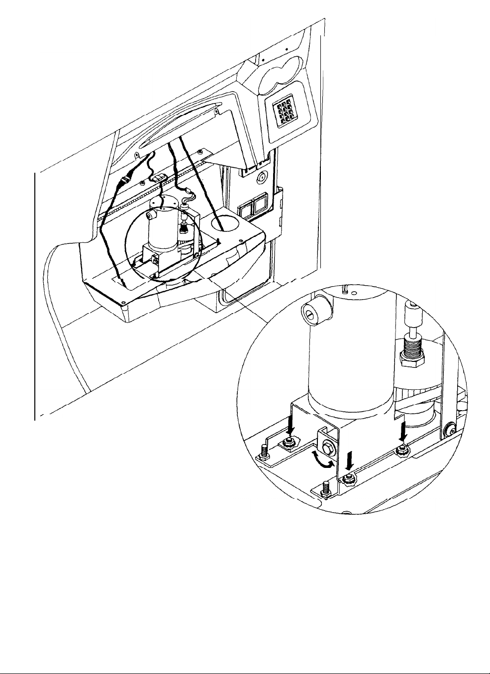
Dashboard and Steering Mechanism
Switch off power to the game. Support the steering wheel. Remove one screw from the upper left corner
and two at the sides of the instrument cluster just above the steering wheel. Remove the support and
lower the dash. Ensure that wires and cables are not pinched or caught in hinge when dash is reinstalled.
While the dashboard is lowered, inspect the motor, pulleys, and belt. Install a new belt if the existing one is
broken or shows signs of wear. There are two nuts on each side of the motor mounting bracket. Loosen
all four bracket nuts and rotate the tension adjustment bolt as necessary. Tighten this bolt until there is no
belt deflection, then loosen it one full turn to provide correct tension. Tighten the motor bracket nuts.
4-4
Page 59
Speakers
Switch off power to the game. The woofer is mounted behind a grille at the back of the drivers seat. The
smaller full range speakers are mounted behind the seat headrest grilles. The larger full range speakers
are mounted behind the grilles above the video monitor.
Remove the screws and set the grille aside.
Always remove the upper mounting screws first and replace them last to avoid damage to the speaker.
Remove the speakers from the enclosure and disconnect the wires.
polarity. Do
no t use excess force when removing or tightening mounting screws threaded into p lastic .
Mark each wire to ensure proper
Gear Shift Assembly
Switch off power to the game. Remove shift plate mounting screws. Disconnect cables. Lift up and out.
Pedal Assembly
Switch off power to the game. Unlock and remove the rear door. Disconnect the pedal cable assembly
from the wiring harness. Adjust the seat to the maximum rear position. Remove six outer mounting
screws from the front perimeter of the pedal plate. Pull assembly toward seat until it clears the opening,
then lift it up and away from the cabinet.
Power Supply
Switch off power to the game. Disconnect the line cord. Unlock and remove the rear door. Unplug the
IEC AC. connector and the wiring harnesses from the top of the supply.
Leave the terminal strip alone.
Disconnect the D.C. power cable from the hard disk drive. Do not remove the supply mounting bracket or
the line filter (found on European models only). Remove four front and two rear screws from the supply,
then slide it out of the cabinet. Verify the line voltage switch setting before reinstalling the power supply.
Game Electronics
Switch off power to the game. Unlock and remove the rear door. Remove the screws and slowly swing
the metal enclosure cover open. You may apply power with the cover open if necessary to observe the
indicators. Disconnect cables and remove mounting screws to replace circuit boards. Anti-static bags
and protective containers from new parts must be used to store the component if it is not reinstalled.
Sound l/O Board Assembly
Switch off power to the game. Unlock and open the rear door and the coin door. Remove the screws and
slowly swing the metal enclosure cover open. Carefully note the orientation of the
JAMMA
connector and
the other cables. Extract the harnesses from the board connectors. Remove six mounting screws and
washers from the Sound l/O Board Assembly. Carefully remove the Sound I/O Board, rocking it gently to
separate the PCI edge connector from the CPU Board Assembly. Lii the board up and off the posts.
Upon reinstallation, tighten the screws starting at the center and working toward the outer edge. Use anti-
static bags and protective containers from new parts to store the board if not reinstalled.
CPU Board Assembly
Switch off power to the game. Unlock and open the rear door and the coin door. Remove the screws and
slowly swing the metal enclosure cover open.
Carefully note the orientation of the
JAMMA
connector and
the other cables. Extract the harnesses and the hard disk drive ribbon cable from their board connectors.
Loosen screws and disconnect the VGA cable from the CPU Board connector. Remove the six mounting
screws and washers from the Sound I/O Board Assembly. Carefully remove the Sound
l/O Board, rocking
it gently to separate the PCI edge connector from the CPU Board Assembly. Lift it up and out. Set the
Sound Board aside. Remove six screws and washers holding the CPU Board Assembly to the enclosure.
Carefully separate the CPU Board from the Video Card PCI connector, rocking it gently to separate the
edge connector from the board. Upon reinstallation, tighten the screws of both the CPU Board Assembly
and Sound I/O Board Assembly in order, starting at the centers and working toward the outer edges of the
boards. Use anti-static bags and protective containers from new parts to store the board if not reinstalled.
Video Card Assembly
Switch off power to the game. Unlock and open the rear door and the coin door. Remove the screws and
slowly swing the metal enclosure cover open. Carefully note the orientation of the
JAMMA
connector and
the other cables. Extract the harnesses and the hard disk drive ribbon cable from their board connectors.
Disconnect and remove the Sound I/O Board Assembly and the CPU Board Assembly and set them
aside. Loosen the screws and disconnect the VGA cable from the Video Card output connector. Remove
the Video Card. Use anti-static bags and protective containers to store the assembly if not reinstalled.
4-5
Page 60
Triamp Board Assembly
Switch off power to the game. Unlock and open the rear door and the coin door. Remove the screws and
slowly swing the metal enclosure cover open. Carefully note the orientation of the connector and the other
cables. Extract the harnesses from the board connectors. Remove four mounting screws and washers
from the Triamp Board Assembly. Lii the board up and off the posts. Handle the board by a heatsink.
Use anti-static bags and protective containers from new parts to store the board if not reinstalled.
Wheel Driver Board Assembly
Switch off power to the game. Unlock and open the rear door and the coin door. Remove the screws and
slowly swing the metal enclosure cover open. Carefully note the orientation of the connector and the other
cables. Extract the harnesses from the board connectors. Leave the other end of the ribbon cable
connected to the Sound
Whee!~Driver
Use anti-static bags and protective containers from new parts to store the board if not reinstalled.
Board Assembly,
I/O
Board Assembly. Remove four mounting screws and washers from the
Ci&_theJ)oord
up and off the posts.
Handle the board by the heatsink.
Hard Disk Drive
A computer type Hard Disk Drive stores data for the video and action. Switch off power to the game.
Unlock and remove the rear door. Unplug drive power and ribbon cable from the hard disk drive. Loosen
four screws. Lift the hard disk drive up and out of the brackets. Remove the drive mounting screws.
To avoid risk of damage during installation, mount the hard disk drive in the brackets before connecting
cables. Install the screws before mounting the hard disk drive in the brackets.
When the hard disk drive has been replaced, data from other linked games will be copied onto the new
drive as soon as a registered driver plays one game. No files will transfer until the game has been played.
!
A
CAUTION Do not stack or drop hard disk drives.
shipping container to return the assembly to your distributor.
Battery
A battery on the Sound
switch off power to the game. Unlock and remove the rear door. Remove the screws and slowly swing
the metal enclosure cover open. The battery is on top of an integrated circuit near the center of the circuit
board. Carefully note the battery position and polarity, then gently pry it loose at each end. The integrated
circuit will remain attached to the board. Do not allow metal surfaces or tools to contact the exposed pins.
To reinstall the battery, orient cell over the integrated circuit. The battery is keyed to
not force. Align the battery pins with the holes in the integrated circuit. Press until the battery snaps in.
I/O
Board retains data in memory when the power is disrupted. To remove it,
REMEMBER: HARD DISK DRIVES ARE FRAGILE
Use an anti-static bag and an approved
fit only one way. Do
Set the clock to the correct date and time after removing and replacing the battery. Contests and other
events are controlled by the clock information.
CAUTION
Danger of explosion if battery is incorrectly installed. Replace only with the same
or equivalent type recommended by the manufacturer.
according to instructions printed on the battery or the manufacturer’s packaging.
NOTE: To avoid explosion, all replacement batteries must match the original in size,
voltage rating, and composition. Manufacturer recommended equivalent types
are acceptable. These batteries are designed for very long life. Do not attempt
to recharge these batteries! Avoid direct shorts across the terminals or from
terminals to ground. Remove them from their holders and store in a safe place
until repairs have been completed. Dispose of used batteries according to the
manufacturer’s instructions.
4-6
Dispose of used batteries
Page 61
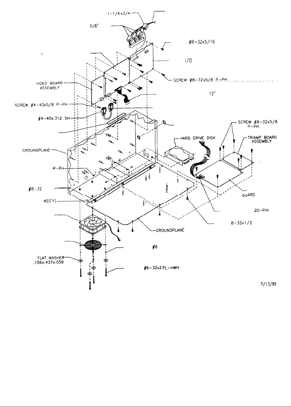
FERRITE BEAD
l-1/4 x3/4\
MAIN HARNESS ASSEMBLY
CPU BOARD ASSEMBLY
JACKSCREW
FLEXIBLE GROMMET
SCREW #6-32x1/4
W/SPRING SEMS
NUT
HINGE (PART OF
GROUNDPLANE
#4-40x.3
GROUNDPLANE
#E-32
KEPS
ASS’Y)
FAN ASSEMBLY
FERRITE BEAD
P-PH
3/8”
\
SPLIT
SCREW
SOUND
RIBBON CABLE, 40-PIN
SHIELDED VIDEO CABLE
GROUNDPLANE COVER
#8-32x5/16
I/O
BOARD ASSEMBLY
SPLIT GROMMET
P-PH
12”
RIBBON CABLE,
SCREW
P-PH SEMS
8-32x1/2
WHEEL DRIVER
AR0 ASSEMBLY
ZO-PIN
FAN GUARD 4”
Fan Assembly
Switch off power to the game.
Remove the cabinet rear door.
LOCKWASHER
SCREW
#6
SPLIT
#6-32x2 PL-HwH
GNC00009
7/l J/99
Remove the screws from the metal cover
of the electronics assembly. To remove a fan, disconnect the power harness and remove the mounting
screws. Note the fan orientation.
Each fan has an arrow molded into its plastic case to indicate airflow
direction. Be certain to reinstall the fans in the proper orientation to assure airflow over the circuit boards.
4-7
Page 62
Dollar Bill Validator
(Use MARS
Dollar bill validators or other currency acceptors may be installed in games that were manufactured with
the additional wiring connector. Switch off power to the game and unplug the A.C. line cord. Unlock the
coin door and swing it open.
Remove nuts, spacers, and cover plate from the door. Change switch settings or make adjustments
before mounting the unit. If the manufacturer has supplied an adapter plate, place it over the door cutout
at this time. Install spacers on threaded studs, then align the validator mounting holes with the studs and
seat the unit in the door opening. Install the nuts and tighten firmly. Attach the ground wire (green with
yellow stripe) lug to the door ground stud next to the hinge. Mate the wiring harnesses and press to fully
seat connectors. Route wires away from door edges and hinge. Inspect for proper bill chute alignment.
Be certain that the dollar bill validator is set to produce long output pulse
Reverse these steps to remove a validator for service or replacement.
Plug in the line cord and
good and bad bills to verify proper operation. Close and lock the coin door when the settings are correct.
AE2411
-U3
U.L. Recognized currency changer)
Read the coin door label for additional information.
turn
on the game. Change the mechanism setup and pricing, then test known
tidfhs
to
avoid
count errors.
4-8
Page 63
SAN FRANCISCO
RUSH 2049’”
CHAPTER
DIAGNOSTIC, AUDIT
&
ADJUSTMENT MENU SYSTEM
,
&
NOTICE: This manual is subject to change without notice. Atari reserves the right to improve
equipment function, design, or components as progress warrants.
Page 64
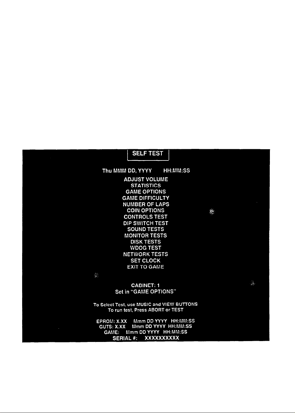
MENU SYSTEM
WHAT IS THE MENU SYSTEM?
The game’s Me nu System is a series of auditing, game adjustment and diagnostic screens. You can
easily access and apply these screens to optimize game performance. For instance.. .
l
Use game audits screens to assess game performance.
l
Use adjustment screens to help you to customize game performance. For instance, you can restore
factory default game settings. You can also calibrate player controls for accuracy.
l
Use diagnostic screens to verify proper equipment operation.
ACTIVATING THE MENU SYSTEM
Open the coin door. Find the TEST MODE switch inside. Press TEST MODE to invoke the Menu System.
The game system responds by exiting Game Mode and entering Diagnostic Mode. The system runs a
brief self-test, and then displays the Self-Test Menu. The Self-Test Menu is the opening screen of the
Menu System.
Game audits, adjustments and diagnostics are line items on the Self-Test Menu. Selecting an item opens
its submenu. Every submenu presents various options that you may act upon.
TYPICAL SELF-TEST MENU
5-2
Page 65
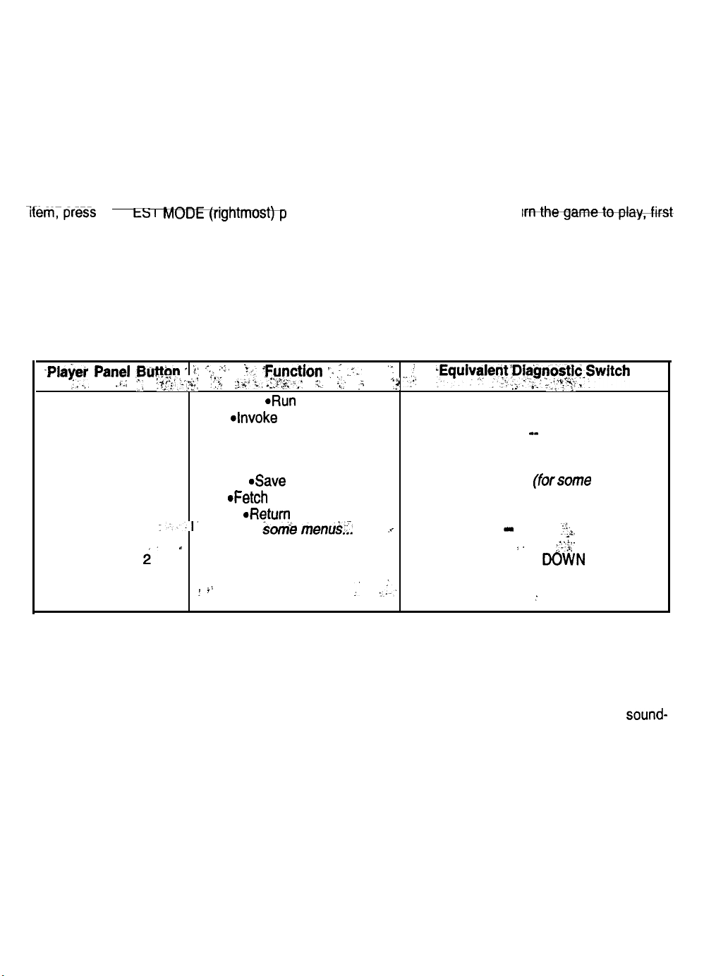
MENU LAYOUT
Menus differ, but related information tends to occupy the same screen locations.
l
The block at the top center of each screen displays the current menu title.
l
Data (menu items, video signals, statistics, reports, etc.) appears in the center of the screen.
l
Messages (explanations, control functions, revision levels) display at the bottom of the screen.
MENU NAVIGATION CONTROLS
Use VOLUME UP and VOLUME DOWN buttons to highlight an item on any menu. (These buttons are on
a bracket inside the coin door.) You can only select one highlighted item at a time. To select a highlighted
Ifem;press the I t> Im
ushbutton inside the coin door. To retu
highlight EXIT TO GAME. Then press TEST MODE.
EQUIVALENT MENU NAVIGATION CONTROLS
In most cases, certain player panel buttons duplicate the functions of the diagnostic buttons. You may find
menu navigation easier with the player panel buttons. Here are the player panel functions within the Menu
System.. .
-pb$ei panel
:*.,, . .
~~~~&q : t:
.i.:
ABORT
F,I
:‘I Ci$*,:$ r:,c. .&“‘I-a’;?~y.:.*- ; kc... .;
“L t-;.
‘Function .,. : ..T.-
4un
test
‘:
*? -,.’
,f
-Equiv5lle~~‘Piegnos~~~~Swltch
~” I~ : .;..: 3.‘,‘y” _
TEST MODE
4nvoke menu option
MUSIC
On some menus.. .
Mm
Move right
Various functions, including.. .
REVERSE
*Save and exit
SERVICE CREDITS (forsome functions)
oFetch more statistics
VIEW1
VIEW
i.
VIEW 3
:..’
*Return to menu
On
Son%
Move left
”
Move down the menu
.i
f I
Move up the menu
menui;i.
.v
:.
:.:-.
-
*-
VOLUME
VOLUME UP
:.-.3,
DOWN
;
I%:+.
-2.
..,l;_
AUTOMATIC TESTS
Whenever you open the Menu System, the Power-On Self-Test (POST) activates. This routine runs
automatically. It can detect faults that cause game or Menu System malfunctions. The Power-On Self-Test
usually takes less than a minute. The test doesn’t display anything. Instead, the system boot loader
indicates the software revision number and serial numbers. The system boot loader also displays a sound-
loading message and other useful information.
5-3
Page 66
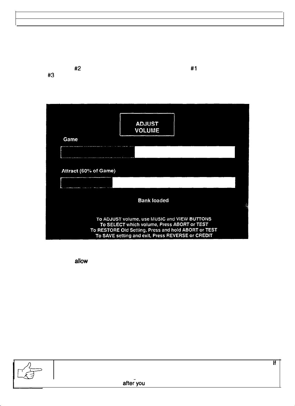
Self-Test Menu (continued)
Adjust Volume Menu
ADJUST VOLUME
Select ADJUST VOLUME at the Self-Test Menu. The Adjust Volume Menu allows you to determine the
sound and music levels of the game. Adjustments can be made in Test, Attract, and Game Modes.
You can adjust the volume level for either the Attract Mode or the Game Mode. Press MUSIC to choose
Game Volume or VIEW
or the VIEW #3 button to raise the volume level. Music plays continuously while this screen is active.
You can adjust the game volume level without entering the Menu System. During Attract Mode or while a
game is in process, open the coin door. Press the VOLUME UP and VOLUME DOWN diagnostic buttons.
#2 for Attract Mode Volume. Press the VIEW #l button to lower the volume level
ADJUST VOLUME MENU
‘Game’ volume settings allow continuous adjustments between zero and maximum. The game will seem
high
more realistic if the player experiences
volume sounds during play. (Performance cars aren’t quiet.)
The ‘Attract” volume adjusts continuously from zero (mute) to full (same as the ‘Game’ setting). For
greater profits, turn up the volume to draw attention to this game.
The length of a graphic bar represents the current volume level. A long bar indicates a louder volume
setting than does a short bar.
You can adjust “Attract” and “Game” volume levels to different values. You can’t set the ‘Attract” level
higher than the level for game play. Reducing the “Game” level automatically reduces the “Attract” level.
Reducing the “Attract” level won’t effect the ‘Game” volume.
Press only the REVERSE button when you make volume adjustments. The ABORT button cancels
settings on the screen and returns levels to previous screen values.
NOTICE:
Volume adjustments affect the volume of sound tests as well as game play.
ff
you set volume to minimum (zero), the speakers won’t produce sounds during audio
a
tests. Set volume levels to
levels to previous settings
high value when you check sound components. Return the
afteryou finish testing.
J
5-4
Page 67
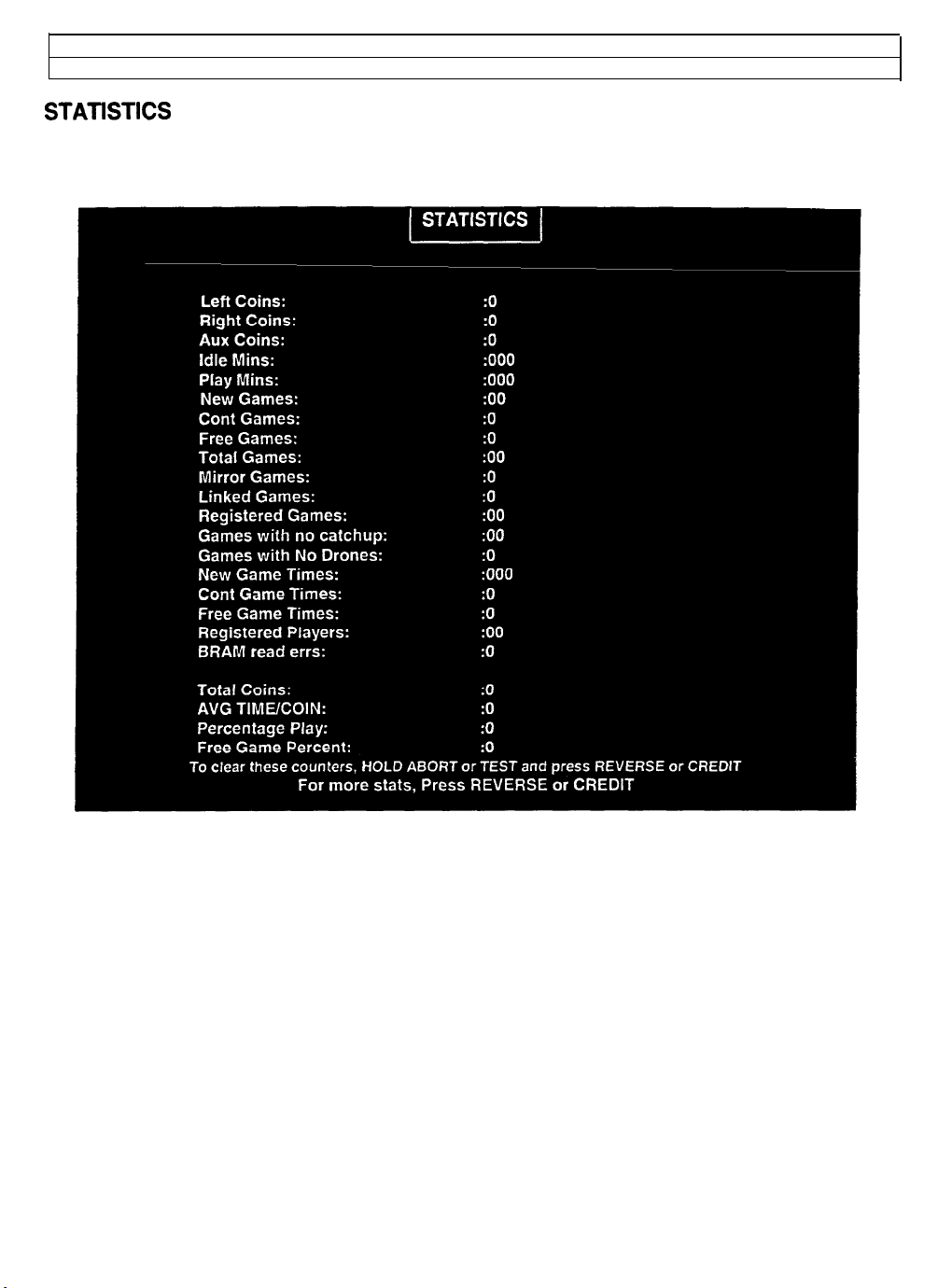
Self-Test Menu (continued)
Statistics Menu
STATETICS
Select STATISTICS at the Self-Test Menu. The Statistics Menu allows you to assess how often and how
well the game is being played. In addition to the earnings, various game aspects are tracked to determine
the player skill levels. The statistics may be reset to zero or allowed to increase after each viewing.
STATISTICS REPORT MENU
The illustration shows how the report screen will look after the game has been reset or is first turned on.
Most of the statistics will increase in value as the game is played. It is normal for some values to remain at
zero: for example, the Earned Games count won’t change unless the cabinet has been set up for free
games, and the
Low counts in both coin and player statistics may indicate that the game is too difficult for the skill levels of
the players at this location. High counts may result if Bonus or Winner Option menu items are in effect.
The difficulty level and other play characteristics may be adjusted from the Game Options menu.
Press only the REVERSE button to view the additional game statistics. If the game has not been played
before, or if the counters have been cleared, the additional statistics won’t be present.
Note and record user messages. These messages can be useful in detecting intermittent conditions.
Record Statistics before servicing this game.
Error
count won’t change if no errors have occurred.
5-s
Page 68
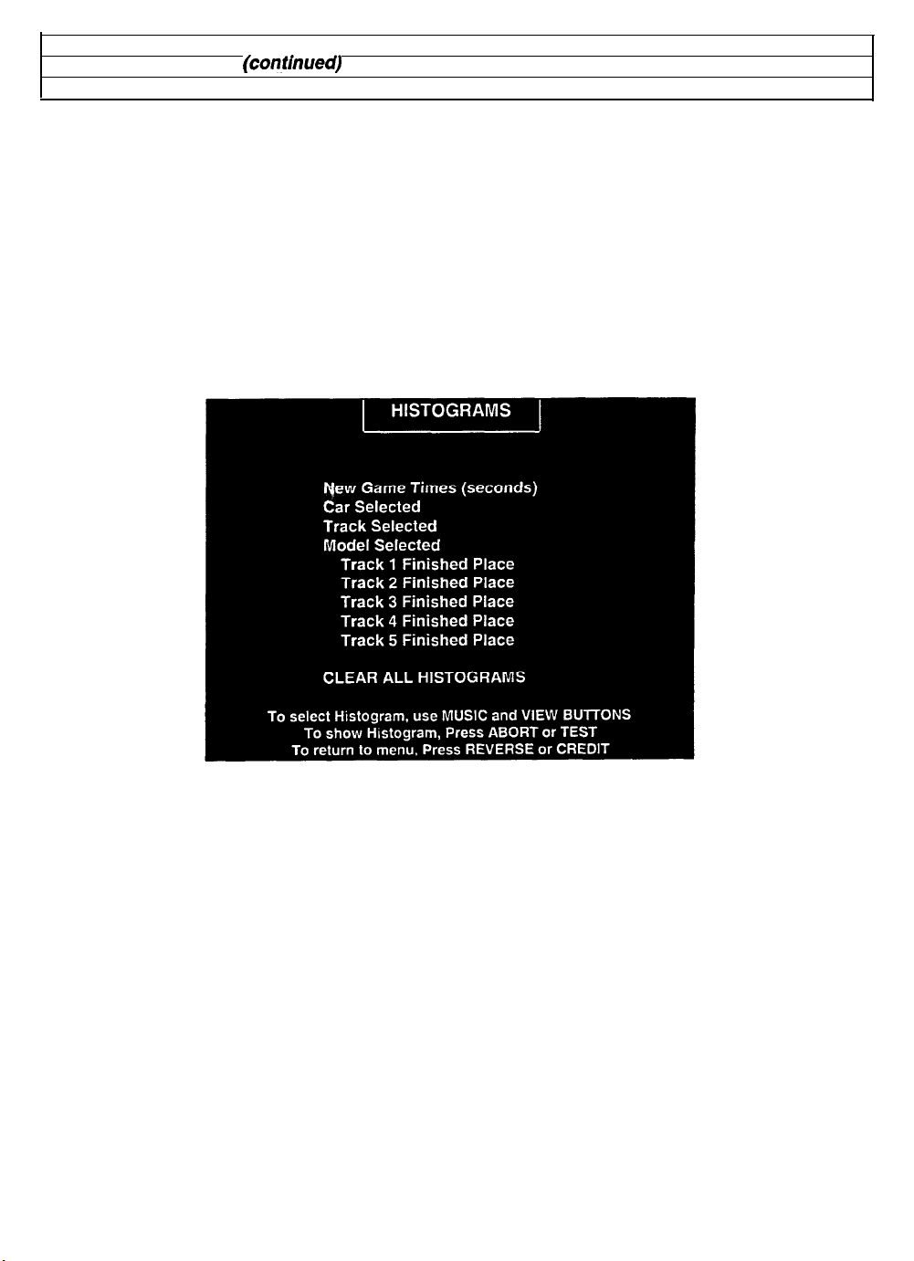
Self-Test Menu (continued)
Statistics Menu
(confhuea)
Histograms Menu
HISTOGRAMS
Select HISTOGRAMS at the Statistics Menu. Press REVERSE or CREDIT to enter the Histograms Menu.
The Histograms Menu allows graphical analysis of statistics and visual comparisons between games.
Histogram screens have no bar graphs until the system has enough data to plot.
Note and record user messages. These messages can be useful in detecting intermittent conditions. The
USER MSGS screen will contain no messages until the system detects an error.
Record Statistics before servicing this game.
Press REVERSE and ABORT together to cancel any changes on the screen and clear all counters to
zero. This deletes all Histograms and User Messages, so examine them before using this action.
HISTOGRAM MENU
5-6
Page 69
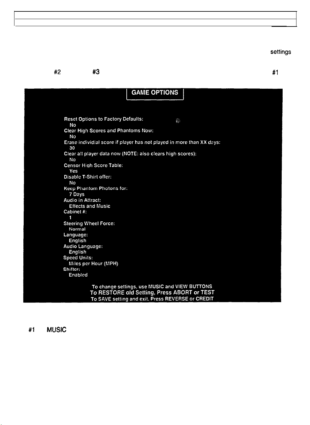
Self-lest Menu (continued)
Game Optlons Menu
GAME OPTIONS
Select GAME OPTIONS at the Self-Test Menu. The Game Options Menu allows you to customize the
game. Each of the variables will change some aspect of game appearance or play. Optimum
cause high player interest and increase earnings.
Use the VIEW #2 and VIEW #3 buttons to select a menu item. Alter variables with the VIEW #1 and
MUSIC buttons. You can change options, or reset them to factory default values after each viewing.
settings
GAME OPTIONS MENU
The illustration shows how this screen will look with all of the factory default settings. Each press of the
VIEW #1 or
MUSIC
buttons will advance a variable through its range of choices. Some items have more
options than others. It is recommended that all of them be examined before one is selected.
You can judge the effects of these options by comparing statistics reports before and after changes. As
players become more familiar with the game, you can add new features or increase difficulty.
To implement finked races, set each cabinet to a different cabinet number. The network uses the cabinet
number to track individual vehicle positions during competition.
STEERING WHEEL FORCE sets the game default value. Players may elect to change this to their needs.
LANGUAGE changes the player information during game play. It doesn’t change menus or tests.
5-7
Page 70
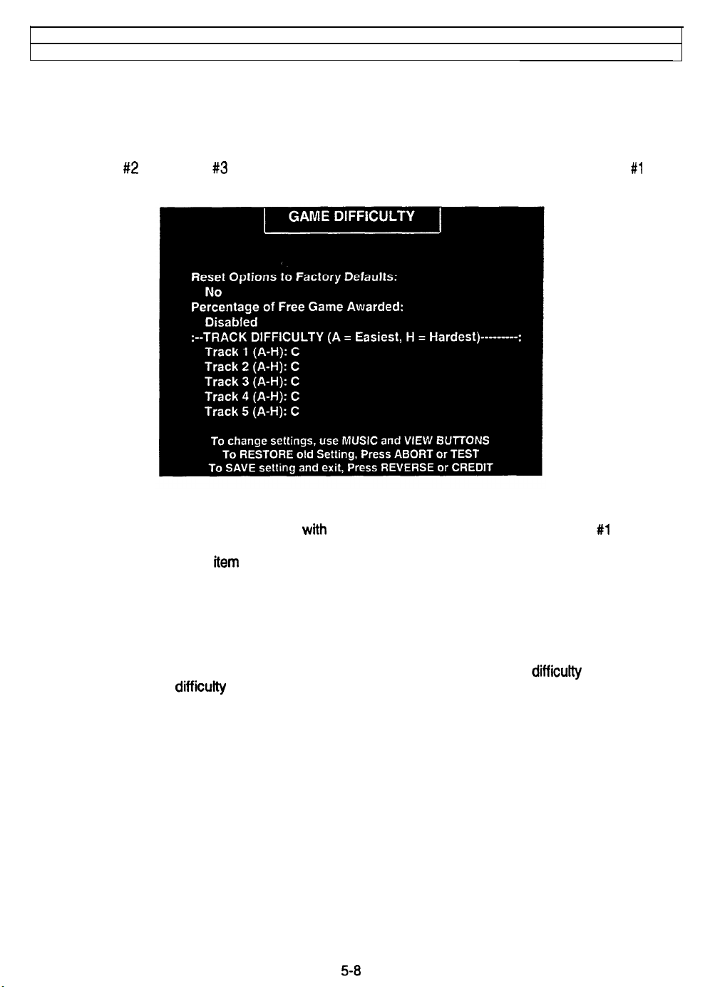
Self-Test Menu (continued.)
Game Difficulty Menu
GAME DIFFICULTY
Select GAME DIFFICULTY at the Self-Test Menu. The Game Difficulty Menu allows you to set track
attributes. Each adjustment affects some aspect of game play. Optimum settings cause high player
interest and increase earnings.
Use the VIEW #2 and VIEW #3 buttons to select a menu item. Alter variables with the VIEW #l and
MUSIC buttons. You can change options, or reset them to factory default values after each viewing.
GAME DIFFICULTY MENU
The illustration shows how this screen looks with factory default settings. Pressing the VIEW #l or MUSIC
buttons advances a variable through its choice range. Some items have a greater range of adjustment
than others do. Examine each
Judge option effects by comparing statistics reports before and after your changes. As players become
more familiar with the game, you can add new features or increase difficulty.
Record track settings befoie servicing this game.
FREE GAME
separate from the other difficufty settings in the game. Free game player incentives may reduce earnings.
Free game are awarded by beating a self-adjusting time on each track. As more free games are awarded,
the time
word “Free” over it represents the time the driver must beat in order to get the free race.
TRACK DIFFICULTY
difficulty reduces the qualifying time requirement between checkpoints. Cars must maintain a higher
speed between checkpoints to stay in the running.
Use free game settings to reward winning players. The free game difficutty adjustment is
is
lowered to make it more difficult to win the next free game. The Phantom Photon car with the
determines how long each player can take to finish the course. Increasing the track
item before selecting one.
5-8
Page 71
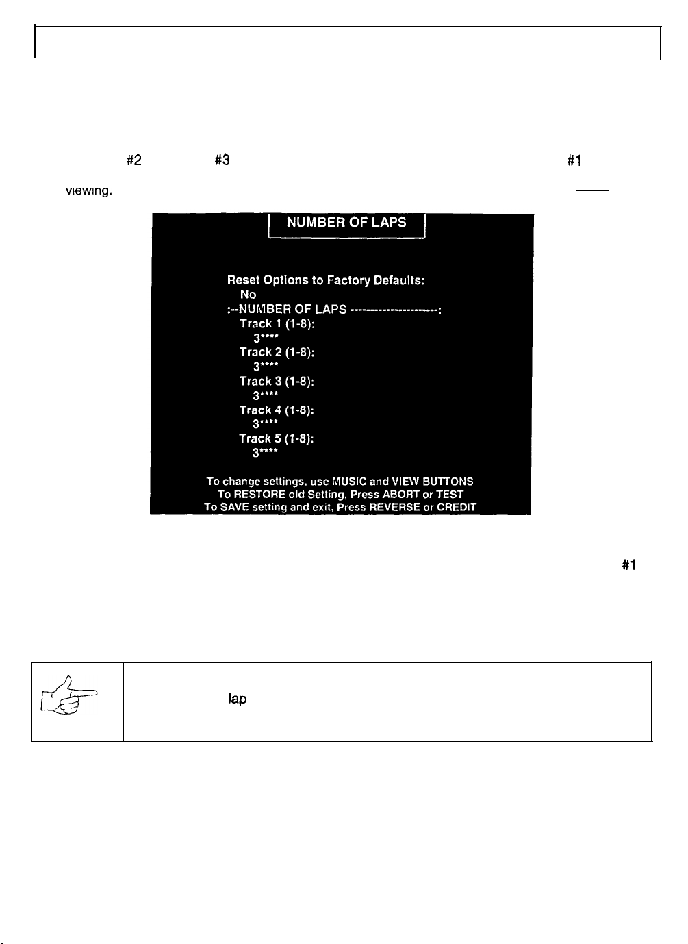
Self-Test Menu
Number of Laps Menu
(continued)
NUMBER OF LAPS
Select NUMBER OF LAPS at the Self-Test Menu. The Number of Laps Menu allows you to set the lap
requirement for each track. Each of the variables will change some aspect of game play. Optimum
settings cause high player interest and increase earnings.
Use the VIEW #2 and VIEW #3 buttons to select a particular menu item. The VIEW #l and MUSIC
buttons are used to change variables. Options may be reset to factory default values or changed after
each viewing.
LAP NUMBER MENU
The illustration shows how this screen looks with factory defauft settings. Each press of the VIEW #l or
MUSICS buttons will advance a variable through its range of choices. Some items have more range of
adjustment than others. It is recommended that all of them be examined before one is selected.
Judge option effects by comparing statistics reports before and after your changes. As players become
more familiar with the game, you can add new features or increase difficulty.
NOTICE: Record lap settings before servicing this game.
NUMBER OF LAPS sets the total length of the race. Short races permit more players per hour on each
game. When the skill levels rise, increase the number of laps as required to maintain player challenge.
5-9
Page 72
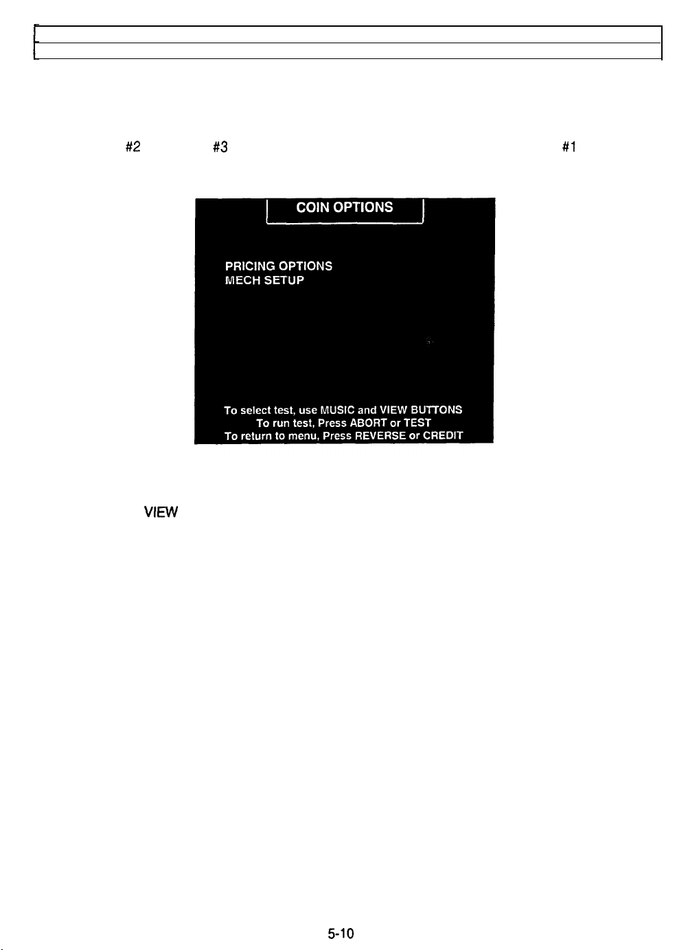
Self-Test Menu (continued)
Coin Options Menu
COIN OPTIONS
Select COIN OPTIONS at the Self-Test Menu. Use the Coin Options Menu to set up coin mechanisms
and select the game pricing. Factory default values can be considered standard.
Use the VIEW #2 and VIEW #3 buttons to select a particular menu item. The VIEW #1 and MUSIC
buttons are used to change variables. Options may be reset to factory default values or changed after
each viewing.
PRICING OPTIONS MENU
MECH SETUP MENU
Each press of the VIEW buttons advances a variable through its range of choices. Some items have more
options than others. View all the options before selecting one.
PRICING OPTIONS
Custom priiing sets credits required to start and continue a game, rewards for quantity buy-in, etc. The
other options will disappear if free play is selected.
MECH SETUP
This screen permits you to add or remove coin or bill mechanisms. Although values are shown for all
devices, changes to unused inputs have no effect if there is no such currency acceptor in game.
5-10
Page 73
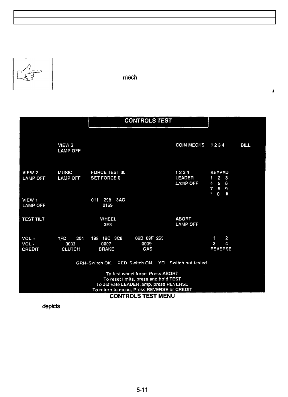
Self-lest Menu (continued)
Controls Test Menu
CONTROLS TEST
Select CONTROLS TEST at the Self-Test Menu. The Controls Test allows you to manually check each
switch in the game.
NOTICE: Some switches (for example, TILT) may not be used with this game. Check
the wiring diagram and the mech setup items.
Activate each switch and the screen indication changes state. Release the switch and the indicator returns
to its previous condition. You can also test any combination of switches together.
The screen depicts control names as they appear on the dash, gearshift, diagnostic switch bracket, etc.
One by one, operate each control. Simultaneously observe the screen. A single menu indication should
duplicate each state change in each control.
Use the Controls Test menu to verify crossed wires, intermittent conditions, and stuck switches.
Press and hold ABORT to test STEERING WHEEL force. During the test, restrain the wheel with one
hand. Watch the display. The force should increase to maximum and decrease to minimum. Change
directions and repeat the test.
Reset the pedal travel limits by pressing and holding TEST MODE. Press and release each pedal during
the test. Digital indicator numbers change each time the computer detects each pedal’s new position. The
numbers turn green to indicate successful pedal calibration.
5-11
Page 74
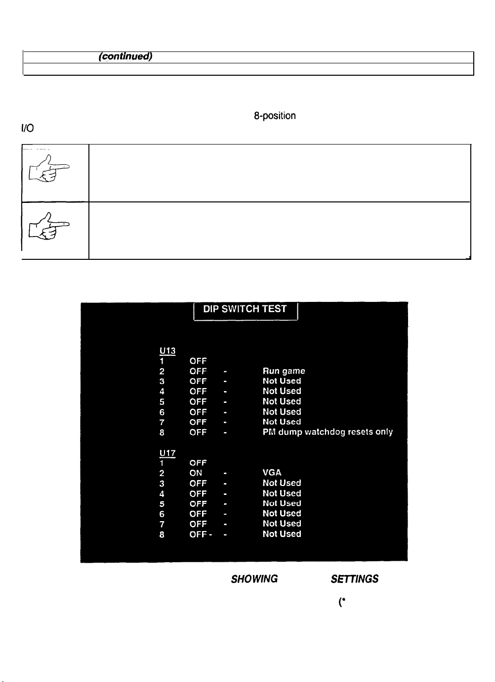
Note and record the Coin Counter reading before beginning the test to avoid subsequent count errors.
Self-Test
Menu
(continued)
DIP Switch Test Menu
DIP SWITCH TEST
Select DIP SWITCH TEST at the Self-Test Menu. Two
I/O Board. The DIP Switch Test Menu reports the positions of 16 switches in these banks.
NOTICE: Don’t change the positions of unused switches. Otherwise you may cause
unpredictable, unstable or erratic operation.
NOTICE: Switch 1 of Bank U17 (monitor resolution) must remain off. Otherwise your
VGA monitor won’t be able to lock onto game sync.
You can change DIP switch positions with power on. Set any switch. Then check the screen to verify that
the new setting is selected.
Enable your changes by
8-position
DIP switch banks reside on the Sound
exiting the Menu System and entering the game.
DIP-SWITCH TEST MENU, SHOWNG
DEFAULT SETTINGS
Refer to the DIP Switch Tables for assistance in choosing switch positions (’ indicates factory defaults).
To exit the DIP Switch Test, press any game button.
5-12
Page 75
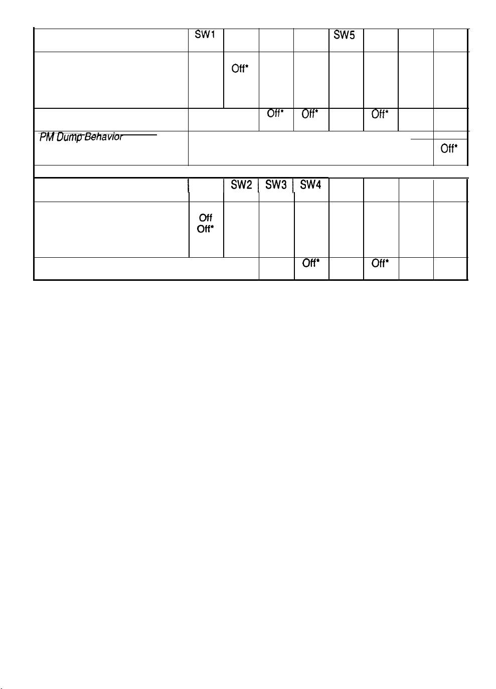
DIP SWITCH TABLES
DIP Switch U13
SW1
SW2 SW3 SW4
Diagnostics vs. Game Mode
Run Game
Run Disk Version of Self-Test
Run EPROM Diagnostics
Off’
Off On
On
Off*
Off
Run Interactive/Power-Up Diags On On
Not Used
Not Used
73Wu~mp Benavior
View Only Watchdog Resets
View All Resets
SW5
SW6 SW7 SW8
Off* Off*
Off’
Off*
Off’
On On On On On
Off*
On
DIP Switch U17
1 SW1 1
SW2
1
SW3
1
SW4
SW5 SW6 SW7 SW8
Monitor Resolution (Pixels)
Standard, 512 x 256
Medium, 512 x 384
VGA, 640 x 480
VGA (again)
$F
On’ Off*
On On
Not Used
Not Used
MONITOR RESOLUTION adjusts the video signal for older video monitors. If you set this switch
Off
On’
off*
off*
On On
Off’
Off*
off* off*
On On On On
incorrectly, the monitor develops two symptoms: It won’t lock onto game video and its remote controls
won’t function normally. The factory default setting is VGA.
5-13
Page 76
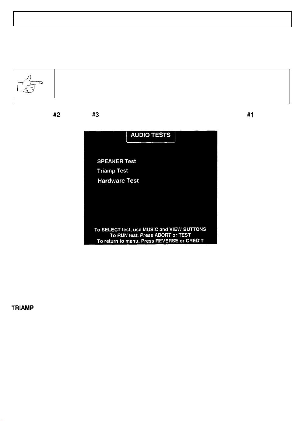
Self-Test Menu (continued)
Sound Tests Menu
SOUND TESTS
Select SOUND TESTS at the Self-Test Menu. The Sound Test Menu verifies that audio components are
connected and operate properly.
NOTICE: The level must be raised for the speakers to be heard. Check the volume
setting before testing.
Use the VIEW #2 and VIEW #3 buttons to select a particular menu item. The VIEW #l and MUSIC
buttons are used to change variables. There are no custom settings or adjustable variables in these tests.
AUDIO TEST MENU
SPEAKER TEST
should be clear and distinct from each other. Each voice must come from the location identified. Refer to
the Adjust Volume Menu for help in increasing loudness for the speaker test.
Use the Audio Speaker Test screen to verify crossed connections, incorrect phase, and distortion.
TRIAMP TEST verifies that the audio amplifier is connected to the game electronics.
sends alternating left and right voice sounds to the front and rear speakers. The voices
5-14
Page 77
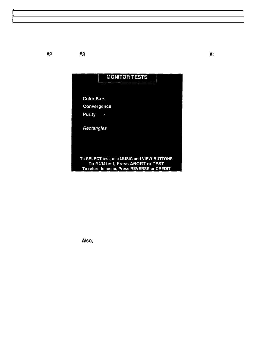
Self-Test Menu
Monitor Tests Menu
(continued)
MONITOR TESTS
Select MONITOR TESTS at the Self-Test Menu. The Monitor Test Menu provides patterns for verifying
monitor performance or making adjustments.
Use the VIEW #2 and VIEW #3 buttons to select a particular menu item. The VIEW #I and MUSIC
buttons are used to change variables. There are no custom settings or adjustable variables in these tests.
MONITOR TESTS MENU
COLOR BARS fills the screen with colored stripes. Use the Color Bars screen to help you to optimize red,
green, blue level adjustments. You can also use color bars during monitor brightness and contrast
adjustments. Each color bar should appear sharp, clear, and distinct from bars on either side. Press the
ABORT button two times to change the color of the screen border. Press REVERSE to exit.
CONVERGENCE
adjusting monitor convergence, linearity, and dynamic focus. The convergence grid and the dots should
be all one color. Look for fringes or parallel images, which shouldn’t appear. Color fringes in the center
grid or dots indicates a need for static convergence. Color fringes at the edges of the screen indicates a
need for dynamic convergence.
indicate a need for side pincushion adjustments. Press the ABORT button two times to change the color
of the screen grid lines. Press REVERSE to exit.
PURITY
adjusting color purity. You can also use purity screens to check black level, intensity, blanking and
degaussing. Each screen should be absolutely uniform from top to bottom and side to side. No retrace
lines, color contamination or noise should be visible. Color screens contaminated with other colors
indicate a need for degaussing or purity magnet adjustment. Press the ABORT button eight times to
change the color of the screen. Press REVERSE to exit.
RECTANGLES
Tests while adjusting vertical height, horizontal width and raster linearity. Each rectangle should be
centered, with all four sides visible. The sides of the background shouldn’t be visible. Press the ABORT
button twice to change the color of the screen. Press REVERSE to exit.
tests fill the screen with 100% of the chosen color at normal intensity. Use the Purity Tests while
tests fill the screen with a grid and a series of dots. Use the Convergence Tests while
Also, the lines should be straight and the dots round. Curved lines may
tests display solid color boxes over a contrasting background screen. Use the Rectangles
If any test reveals a need for adjustment, use the proper knobs on the Monitor Remote Controls board.
5-l 5
Page 78
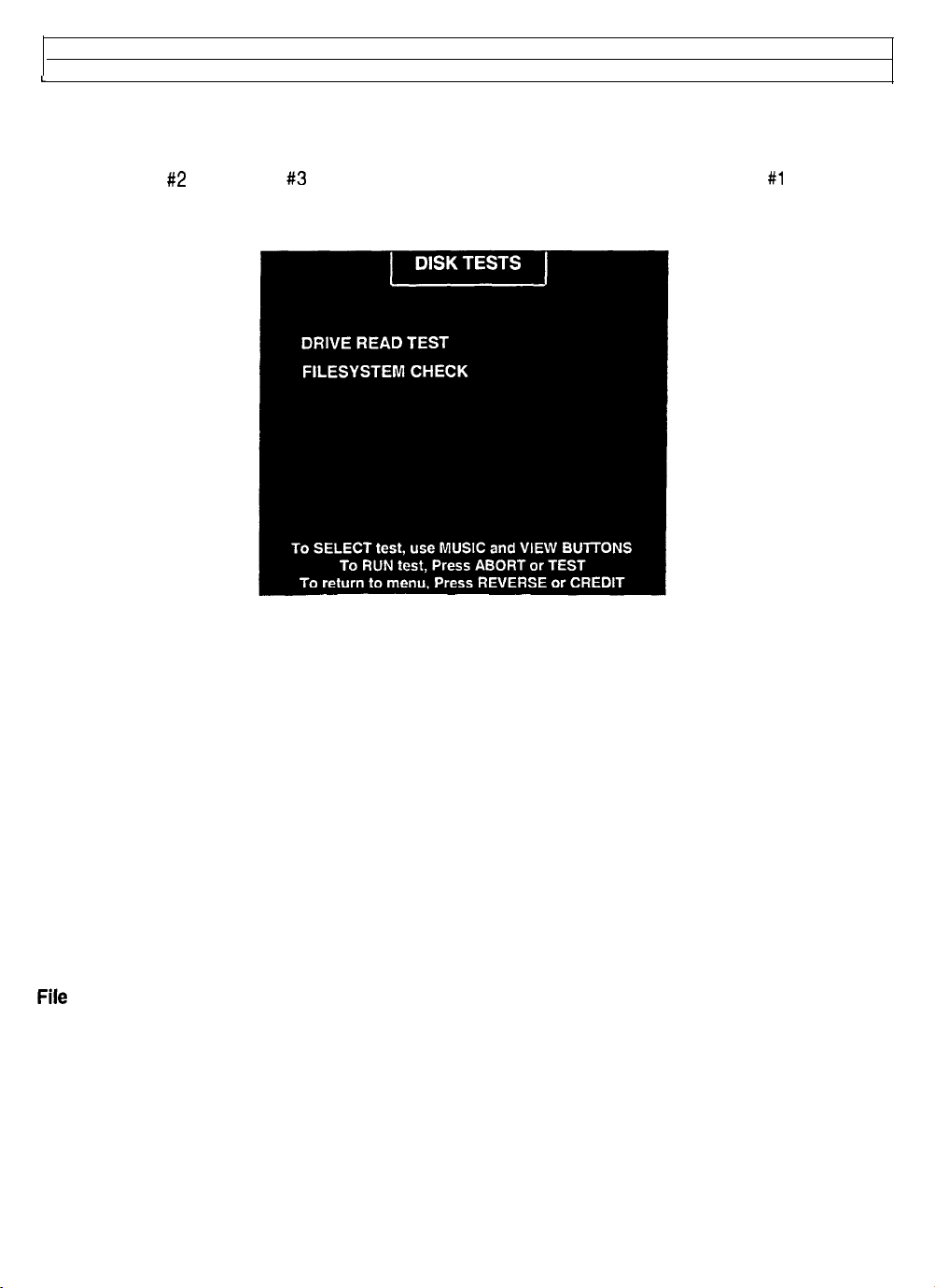
Self-Test Menu (continued)
i
Disk Tests Menu
DISK TESTS
Select DISK TESTS at the Self-Test Menu. The Disk Test Menu allowsyou to check hard drive operation.
Use the VIEW #2 and VIEW #3 buttons to select a particular menu item. The VIEW #l and MUSIC
buttons are used to change variables. There are no custom settings or adjustable variables in these tests.
DRIVE TEST MENU
Hard Drive Connected
This test routine verifies the interface between the CPU Board and the hard drive itself. The processor
requests disk information. Data can’t be retrieved successfully if there is a problem.
Drive ID
Drive ID is an industry standard identification for hard drive type and capacity. This is a manufacturer
hardware number. It doesn’t identify the software or the game program on the drive.
Logical Sector Test
The Logical Sector Test reads and verifies the disk drive, sectors by sector. After checking each sectors
status, the system compares data transfer speed to its acceptance limits.
Tests Completed
These tests run over and over. The number increases each time the cycle repeats (some five minutes).
File System Check
The File System Check routine tests hard drive file data. If the system detects errors, it tries to repair them
(some three minutes per cycle). The system reports error severity and whether game performance will
suffer.
5-16
Page 79
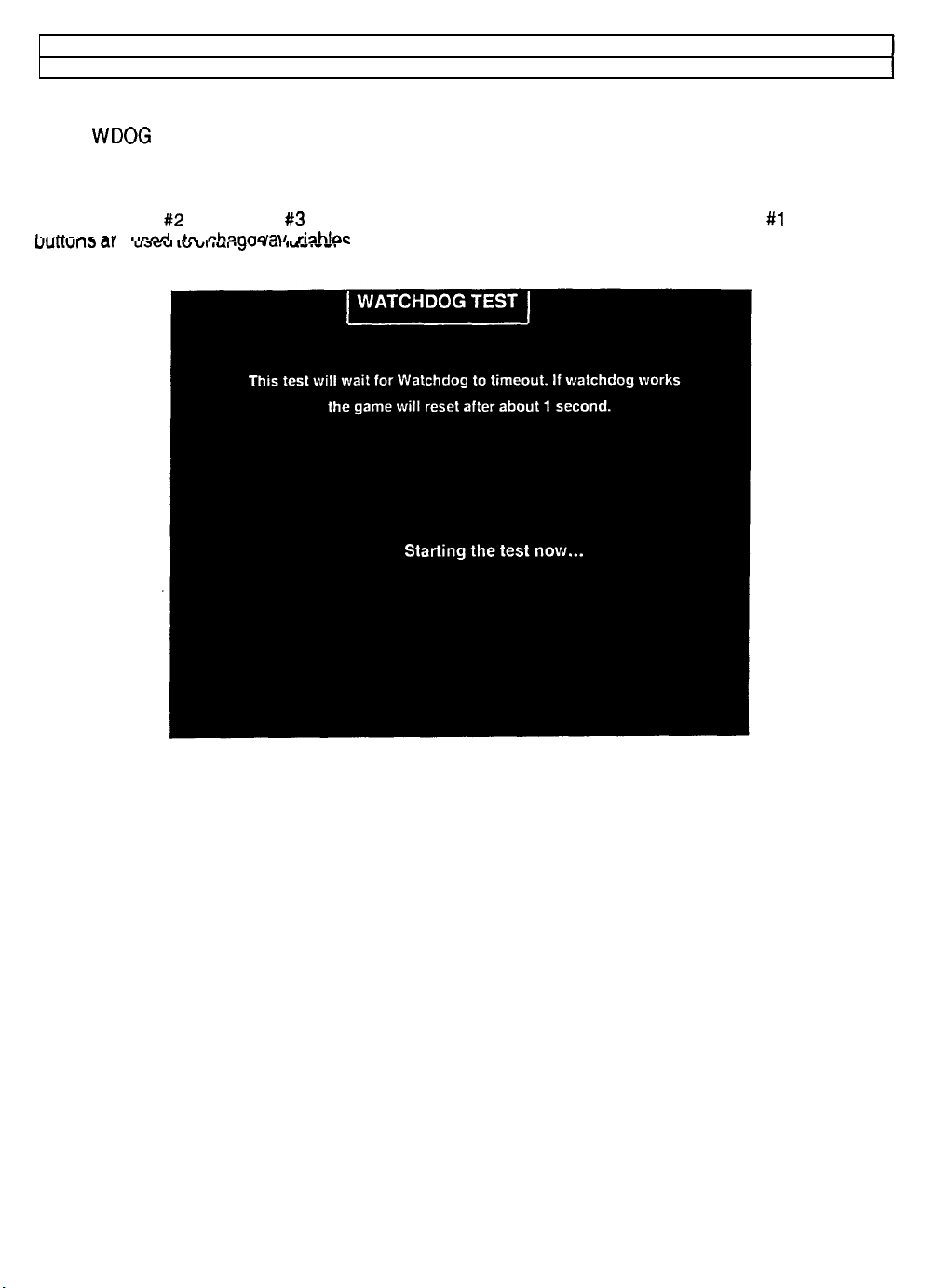
Self-lest Menu (continued)
Watchdog Test Menu
WATCHDOG TEST
Select WDOG TEST at the Self-Test Menu. The Watchdog Test Menu checks the watchdog timer circuit.
In the event of a VGM system crash or loop, the watchdog resets the system. The system then performs
its standard, power-on self-tests. If the system is okay, it reboots normally.
Use the VIEW #2 and VIEW #3 buttons to select a particular menu item. The VIEW #l and MUSIC
L-.~u~-A
uuLLvl 13 QI
-r
e
~~~n~ +A
uacju
,”
eh-nnn 11
vI 1u1 ayu .a, ILIUIVI.
&hrpc
There are no custom settings or adjustable variables in these tests.
WATCHDOG TEST MENU
5-17
Page 80
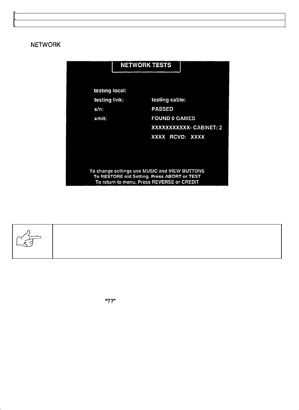
Self-Test Menu (continued’
Network Tests Menu
NETWORK TESTS
Select
communication circuits of linked games. These tests don’t include custom settings or adjustable variables.
NElWORK
TESTS at the Self-Test Menu. The Network Test Menu provides routines for verifying
NETWORK TESTS MENU
Several different options allow cabinets to be finked together for networked competition. This screen
allows you to determine if the linking equipment is networking or not working. The results of these tests
either confirm proper operation or indicate where the problem may be found.
NOTICE: This group of tests checks only system hardware (cables and
communications circuits). Inspect for disconnected or broken cable, hubs, etc.
Individual games are not affected by faults.
Testing Local
This test performs an internal check of the local communication circuits in the game cabinet. It doesn’t test
any cables, hubs, or the other game cabinets. An error message indicates CPU board difficulties.
Testing Cable
‘??”
This verifies complete signal paths.
is a normal response to this test when the game is not linked.
Linked games require all cabinets, couplers, hubs, etc. to be powered on and connected to report OK.
Testing Link
This sends data out from each active game and looks for responses. At least two cabinets must be
networked properly to pass this test. Test results take longer to report as more games become active.
Cabinet ID
Linked games must exchange information back and forth on the network. This screen area shows each
active linked cabinet and confirms data flow. Only one cabinet will transmit data, but all must receive it.
Xmit
This number is a running count of the data packets sent by the local game cabinet. Packet quantities
increase continually until you exit this screen. This cabinet will always receive each packet it transmits.
5-18
Page 81
Rcvd
This number is a running count of data packets collected from the network. The count increases until you
exit. Each linked cabinet must receive packets from the local cabinet or the communications network is
faulty.
NOTICE: This Network Test applies only to the local game cabinet (your present
location). This cabinet is always listed first in the report. Other cabinets report data
received, but only this cabinet report data transmitted.
5-19
Page 82
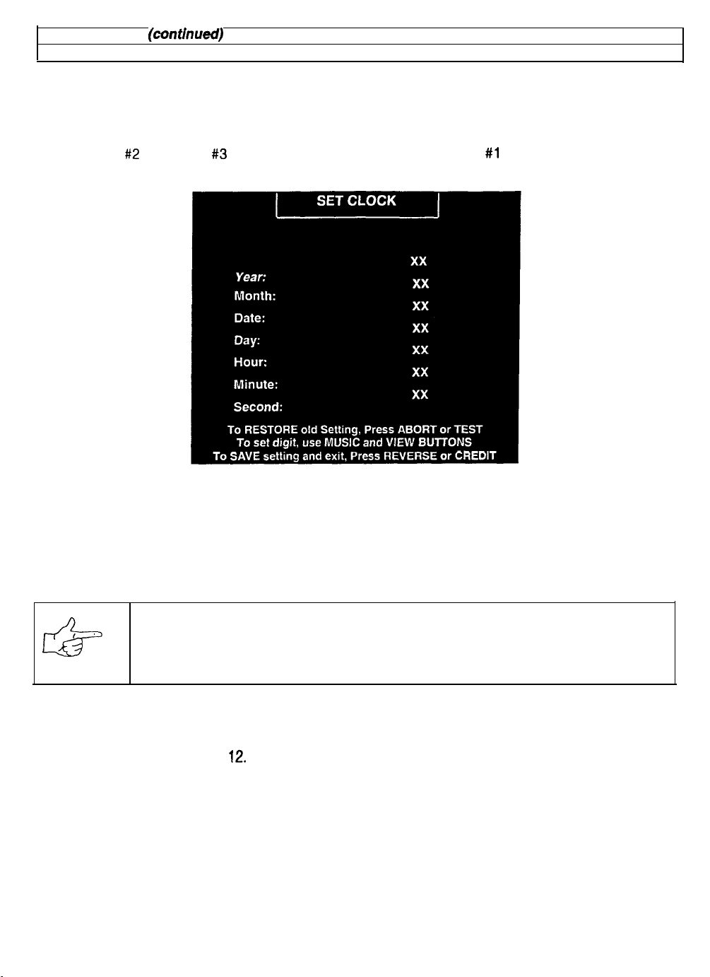
Self-Test Menu (contlnuecf)
Set Clock Menu
SET CLOCK
Select SET CLOCK at the Self-Test Menu. The Set Clock Menu allows you to accurately enter the time
and date. You must set the clock properly if the optional contest feature is to be accurate.
Use the VIEW
#2
and VIEW #3 buttons to select a menu item. The VIEW #l and MUSIC buttons are used
to change the variabtes. There are no custom settings or factory default values for these items.
SET CLOCK MENU
The clock provides accurate time stamps for game statistics. The clock doesn’t affect game operation.
Once set, the clock will run until the battery dies or service or some major fault disrupts circuits.
Periodically examine the top lines of the SELF-TEST screen for the correct time and date.
Press REVERSE to save new information. The ABORT button returns items to the previous values.
NOTICE: The Self-Test Menu shows the time only when requested (not running time).
Incorrect clock settings will affect contest announcements and other features.
Year. Two digits. Range 00 to 99.
Month. Two digits. Range 01 to
Date. Two digits. Range 01 to 31.
Day. Only one digit. Range 1 to 7.
Hour. Two digits. Range 00 to 23.
Minute. Two digits. Range 00 to 59.
Second. Two digits. Range 00 to 59.
12.
5-20
Page 83
SAN FRANCISCO
RUSH 2049’”
CHAPTER
WIRING
Failure to reconnect all ground wires or replace metal shields and covers with each mounting
screw installed and securely tightened may result in radio frequency Interference.
Page 84
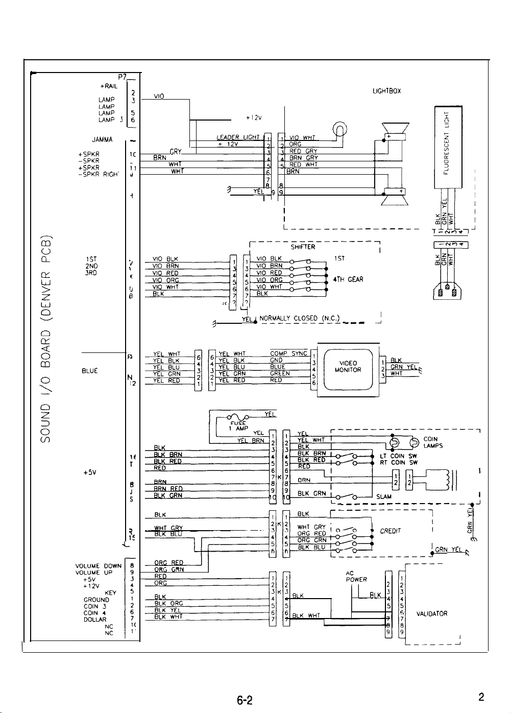
CABINET WIRING DIAGRAM 1
L
LAMP OUT
+RAIL
KEY
IAMP 0 :
LAMP
LAMP
IAMP
JAMMA
+SPKR LEFT
-SPKR LEFT
+SPKR RICH’
-SPKR
RIGH-
KEY
KEY
1ST
GEAR
2ND
GEAR
SRD
GEAR
4TH GEAR
RMRSE
GROUND
I
2
P7,
r
r I
r-----------------------
VI0 WHT
4
3
I
ORG
TO +12V FUSE
l
MAROUEE
LEADER LEFT
LIGHT SPEAKER
LIGHTBOX
-
RED
BRN
RED
BRN
CRY
CRY
WI-IT
WI-IT
;
7
GRN YEL
9 GRN YEL, 9 9 GRN YEL
u ‘1
9 GRN YEL&
6 8 GRN YEL
SHIFTER SWITCHES ARE WIRED
~~~L~ cL$g_(%C-, _ _ _ _ _]
6
ERN
WHT
L----------------
1ST
GEAR
2N0 GEAR
3RD GEAR
4TH GEAR
REVERSE
GROUND
RIGHT
SPEAKER
I
TO
POWER
SUPPLY
1c
I
;1
r(
I
-1
7
r’
N
r:
7
i
/ I
COMP SYNC
GND
BLUE
GREEN
RED
>
F
1
4
1
3
P
1
1
I2
FROM
AC
POWER
CND
LT COIN
RT COIN
+5v
COIN CNTR
COIN CNTR
SLAM
GROUND
CREDIT
TEST
1 ,
2 ,
c
COIN
YEL BRN
2
16
r
I
D
E
:
2
I
2
15
6-2
TO POWER
SUPPLY
___-_---------
r---
FROM
..,~LYI,
VOLUME DOWN I
VOLUME UP
TEST
r----
r-lri
1
BLK
’
:
WHT
6
!GRN
OPTIONAL
DOLLAR
BILL
VALIDATOR
II
---*A
YEL
-7
COIN
METER/
-;h
fi
I
’
I
2
Page 85
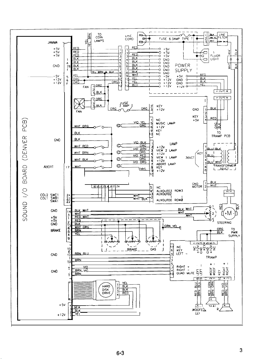
JAMMA
+5v
+5v
+5v
CND
GND
GND 21
GND
CABINET WIRING DIAGRAM 2
r-
3
C
4
:
I
KC
JSE_
RED
TO
LEADER
LIGHT
-0
+5v I
WHEEL DRIVER PCB
1
-1
TO
MUSIC SW
VIEW 3 SW
VIEW 2 SW
VIEW 1 SW
ABORT
SW
COL2
SWCl
COLl SWBI
COLO SWAl
GND
STEER
+sv
+sv
GND
GAS
BRAKE
CLUTCH
KM
KEY
GND
SEAT L
GNO
W
OOF
SEAT R
GND
M
UTE
21
GND
l
GND
27
20
19
18
17
24
2’
2:
1
18
3
1
2
I!
:
z
i
I!
6
1:
1
11
9
5
4
1
i
I
I
WHT BLU
WHT GRN
WHT YEL
RED BLU
ERN
GRN
RED GRN
RFD 0
i3RN :I0
BRN
KEYPAD
‘\/-
CLUTCH
VIEW 3
LAMP
+12v
+12v
NC
I
1
I
WHT RED
WHT ORG
WHT
WHT
BRN
ELK 1
r
L
:
AUXOUTOP
2’
AUXOUTO IROW
-----EC
1
~GRN YEL F
i
Pi--
Ai
ROW2
1
RED
1 NC
6 KEY
LEFT +
J
WOOF
5
WOOF +
TRIAMP
-
+
PCB
+t
1
+I
c5v
GND
CND
+12v
RED
tlLK
ELK
YEL
6-3
I
I
p-Y
WGiEl
--
LLF
I
SEAT
SPEAKER
RIGHT
SEAT
SPEAKER
3
Page 86
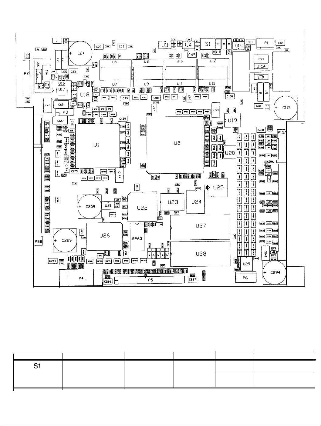
CPU BOARD ASSEMBLY
CPU ASSEMBLY SWITCH
DESIGNATION
Sl
NOTE: This switch resets the CPU Board without turning the power off at the power supply.
LOCATION
EDGE NEAR U4
AND U12
FUNCTION
RESETS AND
RESTARTS
GAME
6-4
POSITIONS
2
STATE
OFF
ON
MEANING
OPERATION
NORMAL
FORCED
RESET
4
Page 87
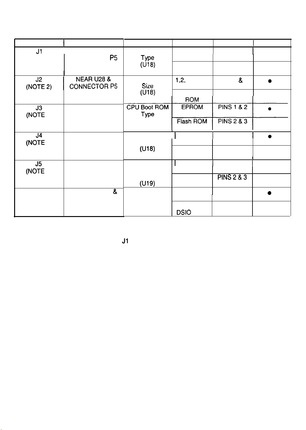
CPU BOARD ASSEMBLY
JUMPER POSITION CHART
DESIGNATION
Jl
(NOTE 1)
(NOYE
1)
(NOYE 2)
(NC?E 3)
J6
LOCATION FUNCTION
1
NEAR U28 &
I
CONNECTOR
NEAR U28 &
CONNECTOR P5
NEAR U28 &
CONNECTOR P5
NEAR U28 &
CONNECTOR P5
BETWEEN U22
U27
CPU Boot ROM EPROM
P5
CPU
“‘“““”
CPU Boot ROM 1 2Mbit ROM I PINS 1 & 2
Expansion Boot j 4Mbit ROM j PINS 1 & 2
&
MEANING
POSITION 1 DEFAULT
PINS 1 & 2
Tme
W f-3)
Boot ROM 1,2, or 4Mbit PINS1& 2 0
m:--
3lZt !
(U18) 8Mbit Flash PINS 2 &
Size
Wlf3)
ROM
Size
W9)
Boot Program
Location
Flash ROM
Flash ROM
1 Mbit ROM PINS 2 & 3
I I I
8Mbit ROM
Boot from PINS 1 & 2
CPU ROM
Boot from
DSIO
ROM
PINS 2 & 3
PlNS2&3
PINS 2 & 3
j
l
3
I
0
j
l
0
NOTES:
1.
2.
3.
Set both jumpers Jl and J3 to EPROM or Flash ROM mode to use such devices.
These jumpers operate independently of one another.
This jumper is independent of the CPU boot ROM size selected.
6-5
Page 88
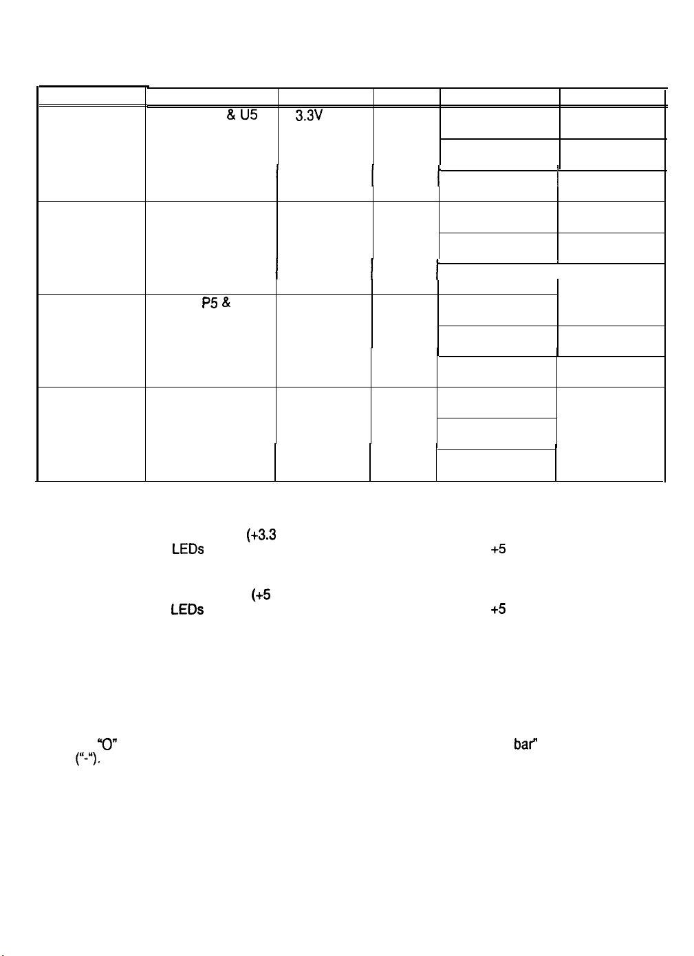
CPU BOARD ASSEMBLY
LED INDICATOR STATUS CHART
DESIGNATION
LED 1
(NOTE 1)
LED 2
(NOTE 2)
LED 3
(NOTE 3)
LED 4
(NOTE 4)
LOCATION
NEAR Cl
NEAR C24 & U6 5v CPU RED
NEAR P5 & U28 HARD DISK GREEN OFF
NEAR U22 & U26
&
U5
FUNCTION COLOR
3.3v
CPU
POWER
INDICATOR
POWER
INDICATOR
DRIVE
ACTIVITY
CPU
ACTIVITY
INDICATOR
RED
RED OFF* *SEE NOTE
STATE MEANING
OFF INSUFFICIENT
ON POWER O.K.
BLINKING
I
OFF INSUFFICIENT
ON
BLINKING
I
ON
BLINKING NORMAL DISK
ON*
BLINKING*
SEQUENTIALLY
POWER
I
POWER
I
FAULT
POWER
POWER O.K.
I
POWER
I
FAULT
NOT IN USE
LOCKED UP
ACTIVITY
4 BELOW
1.
2.
3.
4.
NOTES:
LED 1 monitors CPU power
circuits. If other LEDs are off or blinking at the same time, check the +5 Volt circuits or the game
power supply.
LED 2 monitors CPU power
circuits. If other LEDs are off or blinking at the same time, check the +5 Volt circuits or the game
power supply.
LED 3 flashes when the hard disk is operating during game play. It may light continuously during
startup. If this LED is lighted continuously, there may be a fault with the hard disk drive, which may
be locked up.
LED 4 initially indicates program start-up stages.
device. Under normal conditions, it displays a lowercase “b” or a sequentially blinking segments in
“0”
pattern. During any of the self-test screens, it displays a “bouncing bar” resembling a hyphen
an
(I‘-.).
(+3.3
Volts). If this LED is off or blinking, investigate the processor
(+5
Volts). If this LED is off or blinking, investigate the processor
It is a seven segment alpha-numeric display
6-6
Page 89
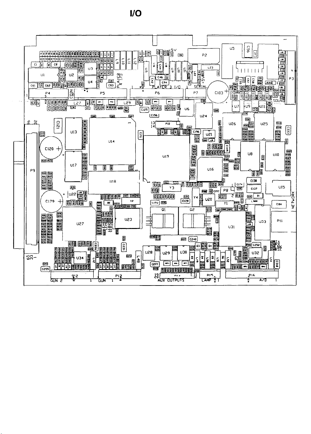
SOUND I/O BOARD ASSEMBLY
I
3
UN2 a I
J-7 d
.
I
I
GUN 1 A
-JIu24I
’
.-mm
I
1
.
I I 1 I
II
-
6-7
7
Page 90
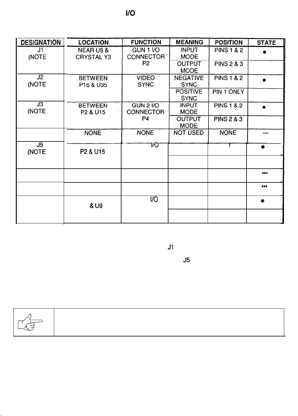
DESlGNATlON
(NO&
1)
(N&E
3)
(NC%
2)
J4
(NOTE 4)
(NOTE 2)
J6
(NOTE 4)
J7
(NOTE 4)
J8
(NOTE 1)
SOUND
i/O BOARD ASSEMBLY
JUMPER POSITION CHART
BETWEEN
P2&U15
NONE
NONE NONE NOT USED
BETWEEN
&
u9
P4
GUN 2
CONNECTOR MODE
GUN 1
CONNECTOR MODE
I/O
P4
NONE NOT USED NONE
I/O
P2
INPUT
OUTPUT
MODE
INPUT
OUTPUT
MODE
PINS
1
& 2
PINS 2 & 3
NONE
PINS 1 & 2
PINS 2 & 3
0
___
___
0
NOTES:
1.
Select the Gun 1 (P2) I/O port mode by setting both the Jl and J8 jumpers to input or output mode.
2. Select the Gun 2 (P4) I/O port mode by setting both the J3 and
3.
Set the Video Sync Signal Polarity to Positive by setting the J2 jumper on pin 1 only. Do not remove.
4.
These jumpers are not required for this game. They may not be present on the board assembly.
NOTICE: The manufacturer wants you to know that guns are not supplied
Connectors are provided for other games that do have guns. We regret your disappointment.
J5
jumpers to input or output mode.
with this game.
6-8
8
Page 91
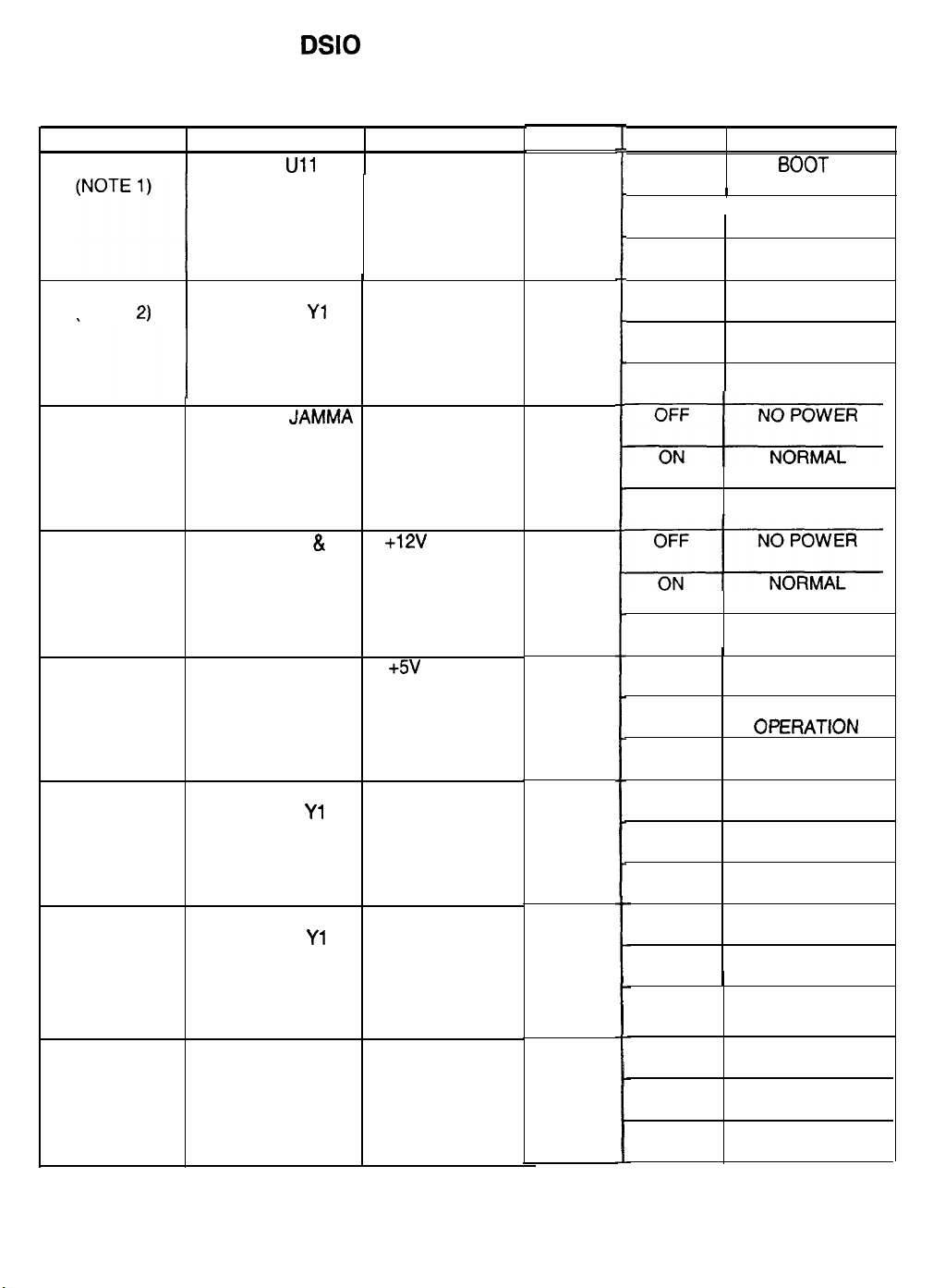
DSIO BOARD ASSEMBLY
LED INDICATOR STATUS CHART
DESIGNATION
LED 1
LED 2
(NOTE
(NOTE 3)
(NOTE 4)
(NOTE 5)
2)
LED 3
LED 4 NEAR U35
LED 5
NEAR U34 & LINKING
CRYSTAL Yl CONNECTOR
NEAR THE JAMMA
CONNECTOR
CONNECTOR P14
CONNECTOR P23
LOCATION
NEAR
Ull
NEAR
FUNCTION
SIO BOARD
ACTIVITY
STATUS
-5V POWER
INDICATOR
COLOR
GREEN
GREEN
RED
STATE MEANING
OFF NO
ON
BLINKING NORMAL
OFF
ON
BLINKING LINK FAULT
BOOT ROM
I
SIO BOARD
I
LOCKED UP
OPERATION
NOT IN USE (NO
GAME LINKING)
NORMAL LINKED
OPERATION
OFF
OPERATION
BLINKING POWER FAULT
&
+12V POWER
INDICATOR
RED
OFF
OPERATION
BLINKING POWER FAULT
+5V POWER
INDICATOR
RED
OFF
ON
BLINKING POWER FAULT
NO POWER
NORMAL
Of ERATION
LED 6
(NOTE 6)
LED 7
(NOTE 7)
LED 6
(NOTE 6)
NEAR U34 &
CRYSTAL
NEAR U34 &
CRYSTAL Yl
NEAR U14 &
CRYSTAL Y 1
Yl
CPU LINKING
ACTIVITY
LINKING
TRANSMITTING
DATA
AUDIO
ACTIVITY
6-9
RED
RED
YELLOW
OFF
ON
BLINKING NORMAL
OFF
ON
BLINKING
OFF
ON
BLINKING NORMAL
NOT IN USE
CPU LINKING IN
PROGRESS
OPERATION
NOT IN USE (NO
GAME LINKING)
SENDING DATA
NORMAL
OPERATION
NO SOUND
BOOT ROM
LOCKED UP
OPERATION
Page 92
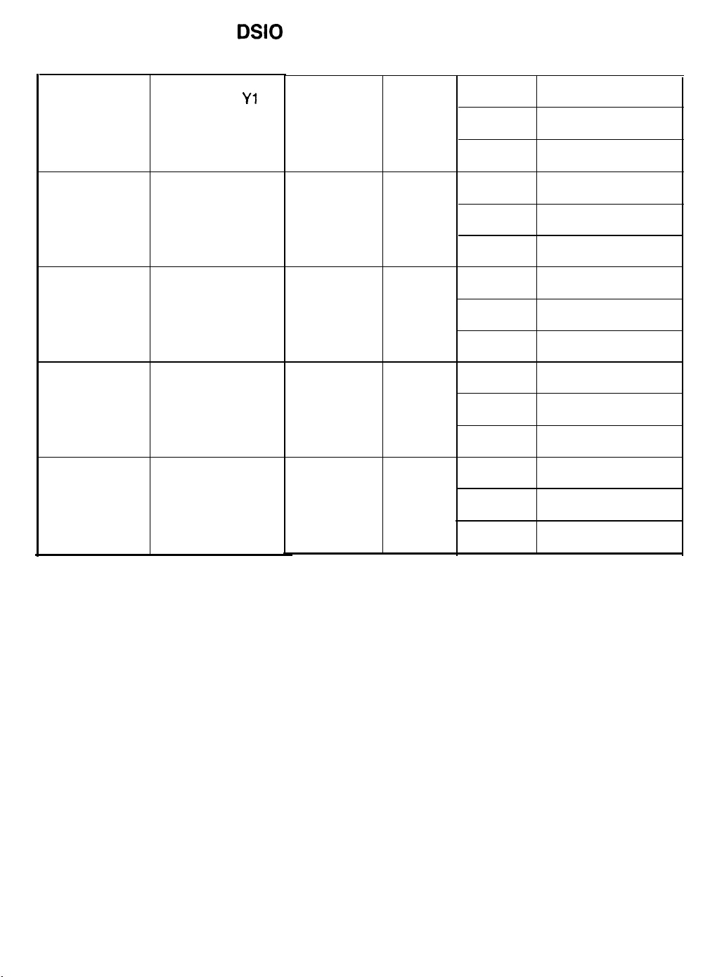
DSIO BOARD ASSEMBLY
LED INDICATOR STATUS CHART (CONTINUED)
LED 9
(NOTE 9)
LED 10
(NOTE 10)
LED 11
(NOTE 11) CRYSTAL Y2
LED 12 NEAR U44 &
(NOTE 12) CRYSTAL Y2
LED 13
(NOTE 13)
NEAR U34 &
CRYSTAL
NEAR U44 &
CRYSTAL Y2
NEAR U44 &
NEAR U44 &
CRYSTAL Y2
Yl
LINKING YELLOW OFF
RECEIVING
DATA
AUDIO GREEN OFF
ACTIVITY (NO AUDIO DATA)
NONE RED OFF NOT IN USE
INTERRUPT YELLOW OFF NOT IN USE
ACTIVITY (NO INTERRUPTS)
DISK YELLOW OFF NOT IN USE
ACTIVITY
ON
BLINKING NORMAL
ON
BLINKING NORMAL
ON CIRCUIT FAULT
BLINKING
ON RECEIVING DATA
BLINKING NORMAL
ON
NOT IN USE
(NO GAME LINKING)
RECEIVING DATA
OPERATION
NOT IN USE
RECEIVING DATA
OPERATION
(NORMAL)
CIRCUIT FAULT
OPERATION
PROCESSING DATA
BLINKING
NOTES:
1.
Boot ROM is active in short bursts only during start up. May appear irregular after a switched reset.
2. Must be on continuously when linked. Intermittent wiring or hub problems could cause blinking.
3.
Monitors a regulated power source. Must be on continuously at all times for correct operation.
4. Monitors a regulated power source. Must be on continuously at all times for correct operation.
5.
Monitors a regulated power source. Must be on continuously at all times for correct operation.
6.
Indicates packet activity occurring on the network. May appear continuous during heavy game play.
7.
This cabinet is sending network packet data. May appear continuous during heavy game play.
8.
Sound ROM is active in short bursts only during start up. May appear continuous during game play.
9. This cabinet is getting network packet data. May appear continuous during heavy game play.
10. Sound ROM is active in short bursts only during start up. May appear continuous during game play.
11. This indicator is not required for this game. It may not be present on the board assembly.
12. Indicates internal game electronics communication. May appear continuous during heavy game play.
NORMAL
OPERATION
13. Hard Disk Drive is active in short bursts only during play. May appear continuous at start up..
6-10
10
Page 93
SAN FRANCISCO
RUSH 2049”
CHAPTER
SEVEN
TROUBLESHOOTING
This game uses complex electronic components that are very SENSITIVE to static electricity.
The following precautions must be observed and followed prior to handling the electronics.
1.
Ensure that the AC. power to the game is turned OFF prior to servicing the electronics.
2.
Discharge any static electricity build up in your body by touching the safety ground stud of
the power supply chassis while the line cord is connected to a properly grounded outlet.
3.
Store the electronic assemblies in an anti-static area. Anti-static bags are to be used to
store or transport the game CPU Board Assembly.
4. DO NOT remove or connect any electronic assemblies when the cabinet power is ON.
Doing so will damage the electronic assemblies and void the warranty.
5.
Always replace ground wires, shields, safety covers, etc. when maintenance or service is
completed. Ensure that all ground and mounting screws are installed and tightened firmly.
Page 94
Coin Mechanism and Pricing Troubleshooting Table
SYMPTOM
.
VGM accepts currency or
tokens, but number of
credits per coin or bill is
incorrect.
VGM won’t accept currency
or tokens.
VGM won’t start.
Audio and video are present.
.
Coin indicators don’t light
CAUSE
Improper settings at
Pricing Menu
Faulty wiring
Improper currency
Faulty coin
mechanism
Tilted coin
mechanism or VGM
Burned-out bulb
Dpen fuse circuit
T
From Coin Options Menu, choose PRICING
OPTIONS MENU. Verify that units and credits
are set correctly.
Check that cabinet wiring is correct for this VGM.
1.
2. Assure that coin meter and coin switches
connect properly to control input wires.
Unlock and open cash door. Empty cash box.
1.
Inspect revenue for counterfeit currency.
Check vault. Remove any items that block path
2.
from mechanism.
1.
Unlock and open coin door. Check each
mechanism for proper mounting.
2. Remove mechanism.
3. Clear currency path.
4. Reinstall mechanism and latch it.
5. Enter Menu System by pressing and holding
TEST MODE switch inside coin door. From
Test Menu, choose CONTROLS TEST. Use
tests to confirm operation of coin switches.
1. Verify that mechanism is level after doors close.
2. Repair or replace coin door if it is bent or
damaged.
If necessary, adjust cabinet leg levelers to keep
3.
mechanisms vertical.
1. Burned-out bulbs mav
Check continuity
2. Replace burned-out bulb with same type.
Check fuse continuity with DVM.
1.
2. If fuse is blown, replace fuse with same type.
3. If fuse isn’t blown, check wiring.
REQUIRED ACTION
Self-
aooear white or darkened.
with~D\jfvl.
CAUTION: Don’t remove or install any connector when power is turned on. Installation
under power will damage the circuit boards or hard disk drive and void the warranty.
7-2
2
Page 95
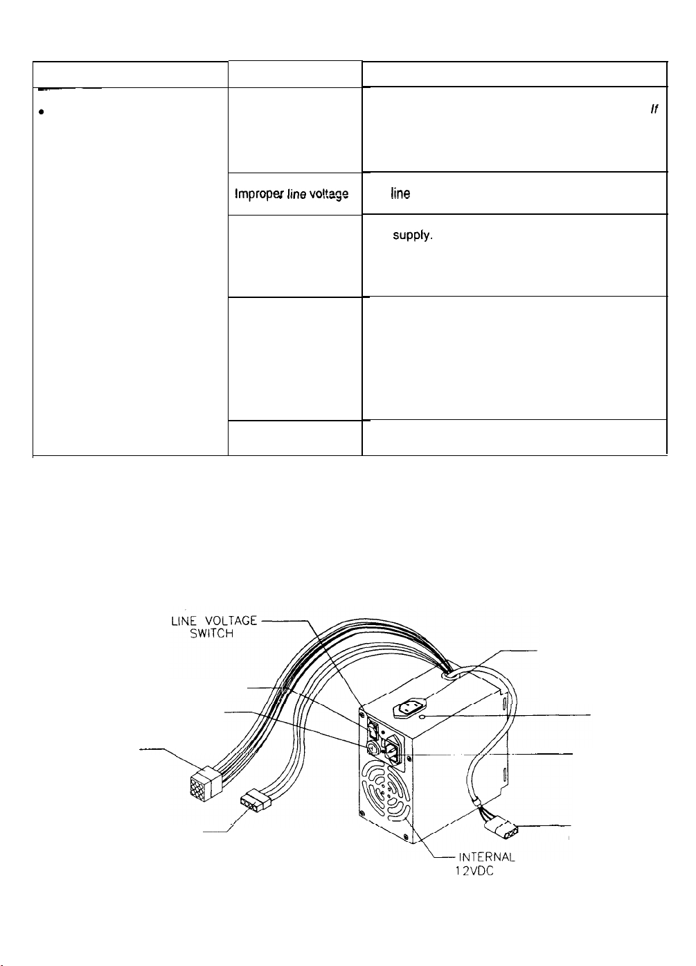
VGM Startup Troubleshooting Table
SYMPTOM
-~
.
VGM doesn’t start.
.
VGM appears completely
non-functional.
.
No audio
.
No illumination
.
No video display
CAUSE
Power problem
lmnrnner ho
,,,y,vy I ..#I" .-V.-J-
switch setting
Open fuse
vnltanc3
Faulty wiring
CPU Board problem
REQUIRED ACTION
1.
Check that VGM power switch is on.
2.
Inspect electronics to see if fans are turning. If
not: Is power supply connected to its power
cable? Is power supply turned on?
3.
Plug VGM into AC power outlet. Verify presence
of AC line voltage.
Turn off VGM power. Unplug AC line cord. Check
!ine
voltage switch. If necessary, set it to agree
with local AC line voltage. Retest VGM.
Turn off VGM power. Examine AC fuse on power
1.
supply.
2. Examine DC fuses inside coin door vault.
3. Replace faulty fuses with identically rated parts.
4.
Turn on VGM power. If fuse opens again, check
DC wiring harness and connectors.
Remove line cord. Test line cord, power plug,
1.
and IEC connector for breaks or damage. Verify
continuity of each wire in cord. Install cord at
power chassis. Press connector firmly to seat it.
2. Check other cables in same manner.
3. Assure that cabinet wiring harness connectors
fully seat in corresponding power supply and
board connectors.
4. Inspect wiring for breaks or damage.
Turn off power for one minute and turn VGM on
again. Power On Self-Test checks electronics.
POWER SWITCH
LINE FUSE
DC POWER
CONNECTOR
HARD DISK DRIVE
POWER CONNECTOR
\
4
/
Power Supply and Line Cord
7-3
AUXILIARY POWER
CONNECTOR
VOLTAGE
ADJUSTMENT
LINE CORD
CONNECTOR
AC POWER
CONNECTOR
12VDC FAN
3
Page 96
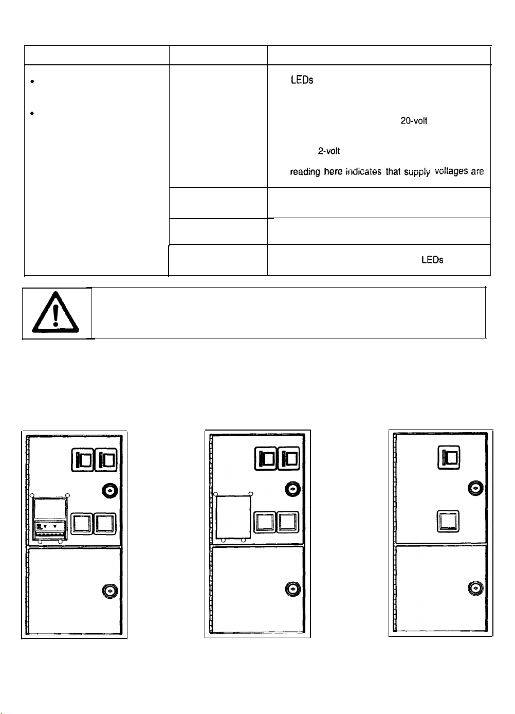
VGM Startup Troubleshooting Table, continued
SYMPTOM
VGM appears nonfunctional.
Currency acceptor price
indicator is illuminated.
CAUTION: Don’t remove or install any connector while power is turned on. Doing so
will damage circuit boards or hard disk drive, and void warranty.
CAUSE
Power problem
Faulty wiring
Improper jumper or
DIP switch settings
Faulty circuit boards
REQUIRED ACTION
1. Inspect circuit boards under low-light conditions.
LEDs
glow if processor circuits receive voltage.
Fan should be turning. These indications prove
presence of DC from power supply. Still,
voltages or signals may not be normal.
2.
Turn on VGM power. Using
digital voltmeter, measure DC voltages at power
connector pins.
3. Using
1.
2-volt
measure same DC voltages as above. Any
reading here indicaies ihai SUpplL’ voltages are
unstable and may contain ripple or noise.
Turn off VGM power. Assure that wiring harness
connectors attach and fully seat onto mating
board connectors.
Verify that circuit board jumpers are set as
intended. Check DIP switch settings.
Run power-up self-test sequence. Note errors or
failures during tests. Compare
indicator status charts. Note discrepancies.
AC setting on digital voltmeter,
20-volt
LEDs
DC setting on
with LED
Front View of Coin Doors
7-4
4
Page 97
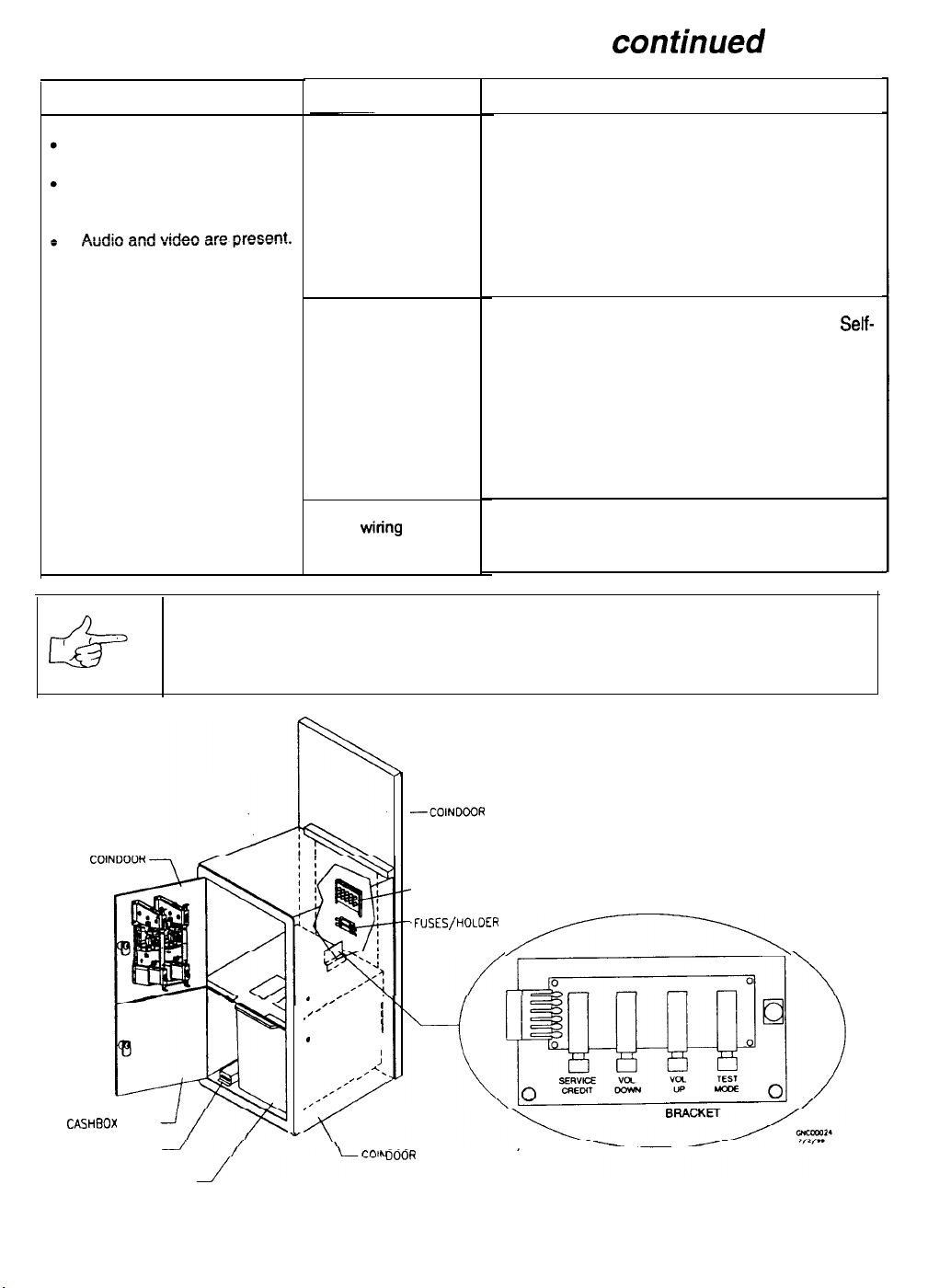
VGM Startup Troubleshooting Table, confinued
SYMPTOM
VGM doesn’t start.
VGM accepts currency or
tokens.
CAUSE
Faulty coin
mechanism
Faulty switches
Faulty
wiring
REQUIRED ACTION
Unlock and open coin door. Check each
1.
currency acceptor to assure proper mounting.
Verify that each release latch is closed and
locked. Does mechanism accept and reject
currency correctly? Test mechanism with good
and bad coins.
2. Inspect to see if external acceptor indicators
(Pricing, Flashing Arrows, etc.) are lit.
Verify that each acceptor operates properly by
1.
placing it in working VGM. Replace bad parts.
1. Enter Menu System by pressing and holding
TEST MODE switch inside coin door. From
Test Menu, choose CONTROLS TEST. Use
tests to confirm operation of each switch.
2. Assure that no loose parts or wires are caught in
switch contacts.
3. Check for continuity in each suspect switch
connection (Common to Normally Open or
Common to Normally Closed).
4. Replace faulty switches (bent levers, broken
actuators, etc.).
Assure that no wires are caught in hinges,
1.
latches or switch contacts.
2. Check wiring continuity from circuit board
connectors to acceptors.
~
Self-
CASHBOX
COIN METER
DOOR
CASH TUB
NOTICE: Gearshift switches are wired for normally closed operation. The other
switches are wired for normally open operation. Reconnect wires to proper switch
terminals.
-COINDOOR WOOD PANEL
SHOWN FOR REFERENCE
-MONITOR CONTROLS
.FUSES/HOLDER
.
/’
.’
.
.’
,’
J
/
,
,
8
,
I
I
;
,/A.
,’
I’
__.R
VAULT ASSEMBLY
,/,------\
TEST SWITCH
Interior View of Coin Door and Cash Door
7-5
5
Page 98
Audio Troubleshooting Table
SYMPTOM CAUSE REQUIRED ACTION
.
No audio
.
Video is present
.
VGM appears to operate
normally
.
Constant low hum from all
speakers.
.
Audio is distorted, muffled or
has missing frequencies.
.
Dead sound channel
Improper volume
setting
Faulty wiring
Faulty or obstructed
speaker
Faulty Audio Board
Faulty wiring
Faulty Sound
Board
Faulty power supply
Faulty or
speaker
Faulty wiring
Faulty speaker
Faulty circuit board
Faulty wiring
I/O
improper
Enter Menu System by pressing and holding
TEST MODE switch. From Self-Test (Main)
Menu, choose ADJUST VOLUME. Check that
Attract Music is on (enabled). Verify that all
volume levels are set well above zero. If
necessary, change levels to make VGM audible.
Turn off VGM power. Assure that wiring harness
connectors attach and fully seat onto mating
board connectors. Verify that harness connects
to circuit boards. Check audio cable connectors
in same way.
Remove grilles and inspect speakers. Free
speaker cones, terminals, mounting screws and
magnets of loose parts or wires.
Verify proper operation of Audio Board by
placing it in working VGM.
1.
Check that cabinet wiring is correct for this VGM.
2. Verify that cabinet wiring provides separate
wires (not common return) for each speaker.
3. Check connection of all cabinet ground wires.
1. Run power-up self-test sequence. Note errors
that VGM finds during tests. Compare Sound I/O
Board
LEDs
with LED indicator status charts.
Note discrepancies.
2.
Verify that Sound I/O Board operates by placing
it in working VGM. Replace bad parts.
Using 2 Volt AC setting on digital voltmeter,
measure voltages at speaker terminals. Any
reading indicates unstable supply that may
contain ripple or noise.
1.
Turn off VGM power. Remove grilles and check
speakers. Assure that speakers are full range
(100 to 10,000 Hz response) and rated for at
least 20 watts. Woofers must be rated for at
least 40 watts.
2. Verify proper speaker operation by connecting
speaker in question to working VGM.
Multiple-speaker installations: Check
reversed wires at one speaker. Weak low
frequencies and thin or hollow sound quality is
symptom of incorrectly phased speakers. Sound
tests may not detect this condition, but you can
hear it during VGM operation.
1. From Self-Test Menu, choose SOUND TEST.
Recheck speakers with audio signals provided
by test.
2. Verify proper speaker operation by connecting
speaker in question to working VGM.
Run power-up self-test sequence. Note errors
that VGM finds during tests. Compare
board
LEDs
with LED indicator status charts.
Note discrepancies.
Verify that cabinet wiring is correct. Assure that
all speakers connect to audio wires. Check for
broken or shorted wires.
for
Circuit
7-6
6
Page 99
Link Troubleshooting Table
SYMPTOM CAUSE
.
Can’t connect
together
.
VGM doesn’t recognize
VGMs
other players in linking
operation
.
VGM functions normally by
itself
.
Some
VGMs
properly, while others don’t
in group link
Faulty wiring 2.
Improperlinking
hardware
Improper settings
Power problem
Faulty wiring
(3 or more cabinets)
Improper hub switch
setting
Wrong software
version
Faulty wiring
(2 cabinets)
Faulty wiring
(3 or more cabinets)
REQUIRED ACTION
1. Don’t extend linking cables that come with VGM.
InStall required crossover between VGM
cabinets. Each coupler connects two cabinets
(one pair). Don’t use standard telephone
couplers or wiring to link cabinets.
3. Use only
twisted-pair wiring for VGM data.
Use required network hub for your local network.
Hub Link
connections. Cabinet array completion requires
basic kit brackets and spacers.
1.
Record any error messages that occur during
self-test.
2. From Self-Test (Main) Menu, choose
Adjustments Menu. Then select Linked Play
Adjustments Menu. Assure that you’ve set
LINKED PLAY to ON.
3. Be sure that each VGM has unique ID number.
If hub is in use, verify that power is applied. AC
adapter wires are thin and easily damaged.
1.
Inspect hub indicator lights. Each active port
should have illuminated indicator.
connects, and that position has no lit indicator,
check for cable continuity from hub to cabinet.
2. Assure that no loose wires catch in hinges,
doors, or under cabinet.
3. Verify that linking cable connects to Network
Board at each
4.
Verify that each linking cable operates properly
by placing it in working VGM.
1.
Assure that switches on hub are set correctly
according to Hub Link Kii instructions.
(Networked cabinets don’t require couplers. Hub
has electronic crossover.)
2.
Inspect hub indicator lights for link activity. See
manufacturer’s literature for diagnostics.
Verify that all linked cabinets use same software
version. Otherwise,
recognize each other. Contact your distributor.
Insert crossover connections between coupled
1.
cabinets. Standard couplers appear identical to
devices supplied with cabinets, but don’t include
internal crossover. Use only one coupler, not
tW0.
2. Verify that each linking crossover coupler
operates properly by placing it in working link
between two cabinets.
1. You used additional crossover connector and
cable to extend VGM or hub link connection.
Two crossovers cancel and cause same
problem as no link crossover.
2. Connect cables directly to hub. Don’t use
crossover coupler and hub together in single
network.
3. Separate communications wiring from other
wiring. Wires that must cross should cross at
right angles to limit noise pickup.
lOBase-T,
Ethernet-type, Category 5,
Krt
permits up to four cabinet
VGM’s
computer.
linked cabinets won’t
If,
cable
type
7-7
7
Page 100
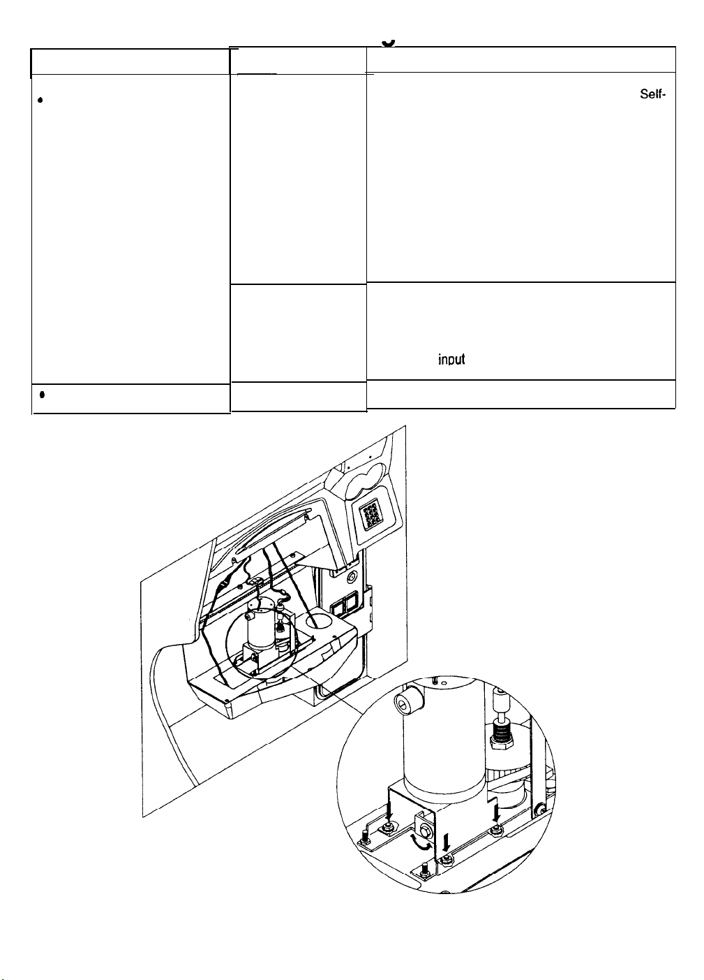
Player Control Troubleshootina
SYMPTOM
.
intermittent or completely
non-functional player
controls
.
VGM starts normally.
.
Steering pulls to one side
CAUSE
Faulty switches or
lamps
Faulty switch wiring
Faulty Wheel Driver
Board
w
1.
2.
3. Check continuity at each switch connection
4.
5.
1.
2.
3.
4.
Table
REQUIRED ACTION
Enter Menu System by pressing and ho lding
TEST MODE switch inside coin door. From
Test Menu, choose CONTROLS TEST. Run
tests to confirm switch operation.
Check for loose parts or wires caught in switch
contacts.
(Common to Normally Open or Common to
Normally Closed).
Verify that control operates properly by placing it
in working VGM.
Verify that dashboard switch light bulbs are type
specified in parts listing. Other types light, but
may produce too much heat. Eventually excess
heat may cause switches to bind.
Check for wires caught in door hinges, latches,
or switch contacts.
Verify that harness connectors are attached and
fully seated.
Assure that control switches connect property to
control
inout
wires.
Check that cabinet wiring is correct for this VGM.
Find power amp on Wheel Driver Board’s large
heatsink. Test and replace bad part or board.
Self-
Adjust Belt Tightness
7-8
8
 Loading...