

Page 1

RAMPAG E
WO RLD
.
TO UR
SECTION
ONE
iivi
OPERATION
NOTICE
Information in this manual is subject to change without notice. ATARI reserves the right to make improvements in
equipment function, design, or components as progress in engineering or manufacturing methods may warrant.
Fill out and mail in the Game Registration card. Be sure to include the game serial number from the label on the
rear of the cabinet. For your records, write the game serial number in the manual. SERIAL NUMBER
l-l
Page 2

SAFETY NOTICES
The following safety instructions apply to all operators and service personnel. Specific warnings and
cautions will be found throughout this manual where they apply. We recommend that you read this page
before preparing your game for play.
!
CAUTION
A
HANDLING ELECTRONIC DEVICES:
SENSITIVE to static electricity. The following precautions must be observed and followed prior to
handling any of the electronics that make up this game.
1)
Discharge any static electricity build up in your body by touching the safety ground stud of the power
supply chassis. This must be done BEFORE touching or handling the electronic assemblies.
2)
Store the electronic assemblies in an anti-static area. Anti-static bags must be used to store the CPU
board assembly. Use the same bag to save the old CPU assembly after the new unit is installed.
DISCONNECT POWER DURING INSTALLATION OR REPAIRS. Always turn the power OFF and
unplug the game before attempting service or adjustments. Installing or repairing PC boards with power
ON can damage components and void the warranty. Be sure that all ground wires are installed securely.
PROPERLY GROUND THE GAME. To avoid electrical shocks, do not plug in the game until it has been
inspected and properly grounded. This game should only be plugged into a grounded 3-wire outlet. Do
not use a “cheater” plug or cut off the ground pin on the line cord.
This game uses complex electronic components that are
USE PROPER FUSE. To avoid electrical shock, all replacement fuses must match the original fuse in
fuse type, voltage rating, and current rating.
POTENTIAL SHOCK HAZARD. This video game system does not utilize an isolation transformer. No
isolation exists between the internal cabinet A.C. system and the external A.C. line voltage.
PROPERLY ATTACH ALL CONNECTORS. Be sure that the connectors on each printed circuit board
(PCB) are properly connected. If they do not slip on easily, do not force them. A reversed connector may
damage your game and void the warranty. Connectors are keyed to fit specific pins on each board.
HANDLE FLUORESCENT TUBE AND CRT WITH CARE. If you drop a fluorescent tube or CRT and it
breaks, it will implode! Shattered glass can fly eight feet or more from the implosion.
EPILEPSY WARNING
A very small portion of the population has a condition which may cause them to experience
epileptic seizures or have momentary loss of consciousness when viewing certain kinds of
flashing lights or patterns that are present in our daily environment. These persons may
experience seizures while watching some kinds of television pictures or playing certain video
games. People who have not had any previous seizures may nonetheless have an undetected
epileptic condition.
If you or anyone in your family has experienced symptoms linked to an epileptic condition (e.g.,
seizures or loss of awareness), immediately consult your physician before using any video games.
We recommend that parents observe their children while they play video games. If you or your
child experience the following symptoms: dizziness, altered vision, eye or muscle twitching,
involuntary movements, loss of awareness, disorientation, or convulsions, DISCONTINUE USE
IMMEDIATELY and consult your physician.
1-2
Page 3

PRODUCT SPECIFICATIONS
Operating Requirements
Location
Domestic
Foreign
Japan 1 OOVAC @
Cabinet Statistics
Ship&o
Width 27” (68.5 cm)
Depth
Height 73” (185.4 cm)
Equipment Characteristics
Video
Standard Resolution RGB
25” (63.5 cm) CRT
Game Characteristics
Plaver Variables
1 to 3 players per game
High Score Recognition
Electrical Power
120VAC @I
230VAC @I
Dimensions
41’ i104.2
Disolav Monitor
cm)
60H.z
50Hz
50Hz
3.0 Amps
2.0 Amps
3.0 Amps
Temperature
32°F to 100°F
(O’C
to 38°C)
Ship&q
Aoorox. 385 Lbs
(ij5
Audio Svstem
Digital Monaural Standard Coin Door
5”
Full Range Speakers
Operator Variables
Coinage, Play Mode,
Difficulty, Volume,
Audits, Statistics
Weiqht Desion
kg.)
(12.7 cm) Coaxial
m
Not to exceed 95% relative
Type
Dedicated Video Game
Currency Acceptors
2 Coin Mechanisms
1 Coin Counter
DiaGnos
Automatic Power-Up Self-Test
Manual Multi-Level Menu System
tics
INSTALLATION
1.
Remove all items from the shipping containers and set them aside.
and the control panel for any damage. Pay special attention to cabinet edges, seams, and corners.
2.
Remove and save the screws at the top and sides of the rear door. Unlock the rear door, then lift it off
of the cabinet and set it aside. Inspect the cabinet interior for any signs of damage. Check all major
assemblies to assure that they are mounted securely.
The coin door keys are located on a key hook inside of the cabinet. Unlock and open the coin door.
3.
The cash box door and rear door keys are located on a key hook attached to the rear of the coin door.
Unlock and open the cash box door. Remove the spare parts stored in the cash box.
4.
Refer to the Cabinet Wiring-Diagram (Section
correctly secured. Do not force connectors; they are keyed
reversed connections may damage your game and void the warranty.
Four leg levelers and
5.
a
leveler with its nut into the threaded
An extra padlock may be installed to secure the rear door. A hasp is located in the spare parts bag.
6.
Remove the two lock bracket nuts from inside the cabinet, above the rear door opening. Slide the
hasp onto the bolts so that it protrudes from the hole in back of the cabinet, then reinstall the nuts.
Modify the lock plate at the top of the rear door. Remove the bolts and nuts from the lock plate, then
7.
rotate the plate so that the slot will be above the door. Reinstall the bolts and nuts and tighten firmly.
&
INSPECTION
nut?
are located in the spare parts bag. Install one nut onto each leveler. Install
Inspect the exterior of the cabinet
3),
and check to see that all cable connectors are
to
fit in only one location.
hole in each comer of the cabinet.
Bent pins and
Do not tighten at this time.
l-3
Page 4

The power cord is with the spare pans. Remove and save four screws from the line cord cover plate
8.
IEC
at the rear of the cabinet. Match the holes on the
firmly to seat the line cord.
Hold the cord flat against the cabinet and reinstall the cover plate (the
plug with the prongs in the receptacle and push
indentation should point down so that the cord exits toward the bottom of the cabinet).
(h:
of
co Dinet
for
refe ren c e
shown
my)
L-l/
Reinstall the rear door onto the cabinet and close it. Lock the rear door and remove the key. If
9.
Line Cord & Plug
required, install the extra padlock through the hasp at this time. Install the screws at the top and sides
of the rear door and tighten snugly. Close and lock the cash box and coin doors.
NOTE
Tamper resistant screws and matching wrench are provided with this game for additional security.
Four tamper resistant screws and one wrench are located in the spare parts bag. If desired, replace
the original screws with the tamper resistant screws. Tighten the screws firmly with the wrench.
Move the game to its intended location.
10.
Lower each leg leveler until the cabinet is stable and level.
Adjust the levelers as required to distribute weight equally on each corner. Tighten the nuts firmly.
Plug the game into a grounded
11.
(34erminal)
switch located on the upper left rear of the cabinet.
AC wall outlet. Switch ON the game, using the ON/OFF
The game will power up and begin
diaanostics. If no errors are found. the aame will automaticallv enter its ‘attract” mode of operation.
1-4
self-
Page 5

CABINET VIEW 1
\
FLLCR.
LAMP ASSEMBLY
CRT GLASS
BEZEL
PLAYER
_
COIN DOOR
CASHBOX
3”TTClN w8
COIN METER
CONTROL PANEL
DaaR
i
1
l-5
Page 6

MID
W A Y
MARCH 1997
16 -4 00 65-l 01
TM
DEDICATED
VIDEO GAME
ODerations
l Kit Installation
.
l Testing
0
Parts Information
l Wiring Diagrams
Midway Games Inc.
3401 North California Avenue
Chicago, Illinois 60618
Manual Includes
&
Operation
&
Problem Diagnosis
Page 7

SERVICING
We recommend that you read the SAFETY NOTICES section thoroughly before beginning service.
Control Panel
Switch off power to the game. Open the coin door. Reach through the coin door opening up inside
the control housing toward the right and left sides of the cabinet. The control panel is held in place by
two latches inside the cabinet which provide constant pressure on the strikes. Lift each latch handle
and unhook the wire fasteners. Grip the joysticks and carefully tilt the control panel back on its hinge.
To return the control panel to its normal position, slowly lean it forward until it rests on the cabinet. Do
not to let the control panel slam down onto the housing. Inspect for binding or pinched wires before
re-clasping the latches. Grip the joysticks and verify complete latch on both sides of the panel.
Viewing Glass
Switch off power to the game. Open the control panel as described above. Loosen three mounting
screws and slide the black metal strip from the bottom of the glass. Carefully slide the glass from the
side grooves, then lift clear of the cabinet and set in a safe place. Clean the glass before reinstalling.
Monitor Bezel
Switch off power to the game. Open the control panel and remove the viewing glass as described in
the paragraphs above. Lift the bezel up off of the monitor and set aside. Clean the labels and orient
them so they can be read correctly (not upside down) when the bezel is reinstalled.
Marquee
Switch off power to the game. Remove the hex-head screws from the black marquee retaining strip
located at the top of the header.
glass from the top of the header and set in a safe place. Clean the glass before reinstalling.
Remove the strip and carefully lift the marquee and the marquee
Speakers
Switch off power to the game. Remove the marquee and the marquee glass as described above.
The grill and the speakers come out from the front of the cabinet.
and remove the nuts on the mounting screws before attempting to remove the speakers from the
enclosure. Carefully reinstall the seals upon completing any task in the speaker enclosure.
Be sure to disconnect the cabling
Coin Counter
Switch off power to the game. Unlock the cash door and swing it open. Remove the cash tubs. The
meter is located on a plate at the vault bottom. Remove the screws and lift the plate just enough to
disconnect the meter wires from the harness. Record the meter count before testing or replacement.
Fluorescent Light Assembly
Switch off power to the game. Remove both marquee glass and marquee. Remove both plastic lamp
locks. Grasp the bulb at each end and give it a quarter turn. Gently pull the bulb straight out to remove
it from its sockets. The starter also requires a quarter turn for removal. Do not force the bulb or
starter during reinstallation. Clean the bulb to remove fingerprints and dust, then reinstall marquee.
To remove the entire light fixture, remove the lamp locks and the bulb as described above.
Disconnect the fluorescent light assembly connector from its power cable. Remove the screws that
hold the assembly to the cabinet, then lift out the assembly.
If you
drop a fiuorescent
!! WARNING !!
tube or a CRT and it breaks, it will implode!
l-6
Use care in handling.
Page 8

CABINET VIEW 2
ElN/tIlFF S’WITCH .-,
VENT/PULL HANDLE -,
REAR
DOOR
I
LOCK
BRACKET-
!
r
I
POWER
SUPPLY
COIN
VAULT
CPU
BOARD
-
-
-
==
z3
/
-
DOOR BRACKET
CASTER
LINE CORD COVER
1-7
Page 9
+ Coin Mechanism
Switch off power to the game. Unlock the coin door and swing it open. Unlatch and remove each
coin mechanism separately to clean or replace with a different type. Ensure that mechanism seats
fully in the holder upon reinstallation. Close and lock the release latch, then close the door. Turn on
the game and change the mechanism setup, then test known good and bad coins to verify operation.
+ Dollar Bill Validator
(Use JCM DBA
Dollar bill validators or other currency acceptors may be installed in games manufactured with the
additional wiring connector
Unlock the coin door and swing it open. Read the door label for additional information. Remove nuts,
spacers, and cover plate from the door. Change switch setting or other adjustments before mounting
the unit. If the manufacturer has supplied an adapter plate, place it over the door cutout at this time.
Install spacers on threaded studs, then align the validator mounting holes with the studs and seat the
unit in the door opening. Install the nuts and tighten firmly. Attach the ground wire (green with yellow
stripe) lug to the door ground stud next to the hinge. Mate the wiring harnesses and press to fully seat
connectors. Route wires away from door edges and hinge. Check for proper bill chute alignment.
Plug in the line cord and turn on the game. Change the mechanism setup and pricing, then test
known good and bad bills to verify proper operation. Close and lock the coin door when correct.
+
Monitor
Switch off power to the game. Open the control panel, remove the viewing glass and the monitor
bezel. Open the cabinet door and disconnect all monitor cables. Remove the four flange nuts
securing the monitor’s mounting brackets to its mounting panel. Pull the monitor carefully from the
cabinet and set in a safe place. Clean the face of the CRT before reinstalling the bezel and the glass.
-Ol,-02,-45, Dixie-Narco USA-15 or other U.L. Recognized currency changers)
(DBV
ready). Switch off power to the game and unplug the A.C. line cord.
CAUTION
THE VIDEO MONITOR IS HEAVY, WITH MOST OF THE WEIGHT TOWARD THE FRONT OF THE
ASSEMBLY. BE SURE
The monitor does not require isolation from the A.C. line voltage in normal operation.
However, when operating outside the cabinet or servicing the monitor on a test bench, YOU
MUST ISOLATE THE MONITOR FROM LINE VOLTAGE WITH AN ISOLATION TRANSFORMER.
+ Power Supply
Switch off power to the game. Remove screws, then unlock and remove the rear door. Unplug the
IEC A.C. connector from the rear of the supply and the D.C. connector from the front.
front and two rear screws from the supply, then lift off of the power chassis. Note the voltage setting.
To reinstall the power supply, set the voltage switch to the correct value. Set the supply on the power
chassis and align the mounting holes.
+
CPU Board Assembly
Switch off power to the game. Open the front door. If used, remove the RF Cage top to expose the
CPU Board Assembly. Carefully note the orientation of the
the wiring harness. Extract the harness cables and the hard disk drive ribbon cable from the board
connectors. Remove the CPU Board Assembly mounting screws.
and set in a safe place. Anti-static bags and protective containers from new parts may be used to
store the board if it is not reinstalled.
lTlS
FIRMLY SUPPORTED AS IT IS REMOVED FROM THE CABINET.
Install the four screws and the two power connectors.
JAMMA connector and the other cables of
Lift the board out of the cabinet
Remove two
1-8
Page 10

Memory
The ROM (Read Only Memory) circuits contain the computer operating instructions. Memory devices
are especially sensitive to static charges.
Switch off power to the game. Carefully note the position, then remove using a chip extraction tool.
To reinstall memory circuits, orient a chip over its socket and press firmly to seat pins. Do not force.
I
A
ACAI IT IAN
v-u m IV,.
,nis& arn n an v ct at i r dedri ci t v
#“SJ Y U## , .# .“. ,I Y,“_.,._.., __..- -#w
touching the power supply chassis. This is to be done BEFORE touching
or handling the electronic assemblies.
Battery
Switch off power to the game. Carefully note the position, then gently lift the contact arm to release
tension. Do not bend the arm. Slight finger pressure may be needed to pry the cell from its holder.
To reinstall the battery, orient cell near its holder and slide it in under the contact arm. Do not force.
!
A
CAUTION Danger of explosion if battery is incorrectly replaced.
Replace on/y with the same or equivalent type recommended by the
manufacturer. Dispose of used batteries according to instructions printed
on the battery or the manufacturers packaging.
NOTE: To avoid explosion, all replacement batteries must match the original in size, voltage rating,
and composition. Manufacturer recommended equivalent types are acceptable. Do not attempt to
recharge these batteries: remove them from their holders and store in a safe place until repairs have
been completed. Avoid direct shorts across terminals or from terminals to ground! Dispose of used
batteries according to the manufacturer’s instructions.
Use grounding precautions when handling these parts.
hrlilr i
r,n ifl your _~Q@J _by
MAINTENANCE
Viewing Glass
It is not necessary to switch off power to the game to clean the glass. Apply a mild glass cleaner to a
clean cloth or sponge, then use this to wipe the viewing glass.
the glass! Liquid could drip down into switch or control circuits and cause erratic game operation.
Controls
Use plastic-safe non-abrasive cleaners to avoid damaging parts.
sponge, then use this to wipe controls or panel.
Do not
app/y the cleaner direct/y on the controls!
Cabinet
Use only non-abrasive cleaners to avoid damaging game graphics.
or sponge, then use this to wipe screen clean.
Do not apply the cleaner directly on the cabinet!
l-9
Do not apply the cleaner direct/y on
Apply the cleaner to a clean cloth or
Apply the cleaner to a clean cloth
Page 11

GAME OPERATION
STARTING UP
Each time the game is first turned on or power is restored, it begins executing code out of the boot ROM.
These self-diagnostic tests automatically verify and report condition of the CPU and the game hardware.
If any of the individual tests fails, then an error message will be displayed for each test.
During initial tests, patterns which resemble woven fabric rugs appear on the CRT screen. When the “rug”
patterns end, the screen displays a CPU Board map. Critical integrated circuits are tested one at a time.
Bad devices are indicated in red, good in green. The game will not start when faults are found by this test.
Once all Power-up tests have been passed, the game goes into its “attract mode”. Scenes and sounds
from a typical game are alternated with previous high scores in an endless pattern until game play starts.
Insert currency to start the game. Players select locations and other game variables. Play begins after a
countdown period is completed. The game will progress until time is exhausted. If no more play is
required, the game automatically returns to the “attract mode”.
GAME RULES
INDIVIDUAL PLAY
Insert currency to start the game. The mission is explained and the opening situation is revealed. Press
the nearest START button to choose a creature. The joystick and action buttons control creature activity.
MULTIPLE PLAYERS
Insert currency to start the game. The mission is explained. Press START buttons to choose creatures.
An indicator bar at the top of the screen shows the condition of each creature during
Play instructions are found on the information panel under the video monitor.
competiton.
PLAYER CONTROLS
START Button
This button allow players to begin or continue play. Choose a creature with this button.
This same button has no dedicated function during service.
JUMP Button
The JUMP button lifts the creature up. The joystick affects which direction the creature will jump.
This same button is used to select items from the menus during service.
PUNCH Button
The PUNCH button activates the arms. The joystick affects which direction the creature will punch.
This same button is used to select items from the menus during service.
KICK Button
The KICK button activates the legs. The joystick affects which direction the creature will kick.
This same button is used to select items from the menus during service.
JOYSTICKS
Each player has a joystick to control the movements of an on-screen character.
The joystick is also used to select items from the menus during service.
l-10
Page 12

OPERATOR CONTROLS
CABINET SWITCHES
+
Power Switch
The Power Switch turns off the game during service. It does not reset the game variables.
+
Slam Tilt Switch
The Slam Tilt switch prevents game abuses such as pounding to obtain free games.
+
Monitor Remote Adjustments (inside the cabinet under the monitor)
The Monitor Remote Adjustment Board sets the video dispiay for optimum viewing.
CONTROL SWITCHES
+
Volume Down and Volume Up Buttons
The Volume Down and Volume Up push-button switches increase or decrease game sound levels.
Press either button briefly to make minor changes. Press and hold a button to make major changes.
Volume may also be changed with the joysticks and buttons when the menu system is active.
NOTE
For greater profits, adjust your volume levels to a loud setting to draw attention to this game.
+
Begin Test Button
The Begin Test push-button switch enters the menu system.
run the automatic tests. Press and hold the Test button to get to any of the menu selections.
Press the Begin Test button briefly to
+
Service Credit Button
The Service Credit push-button switch allots credits without changing the game’s bookkeeping total.
NOTE
The coin door must be open to reach the control switches.
____....---------....______
,*’
,/
,,,’
\..*
_.---
_A
/
SERvrCE
CREDITS
*.._
-.
----..
_...---
VOLUUE
DOWN
----..._
--.-__._.........-----
ZLUME
..--
--._
FE”
/--
--._
\
--._
A’
__--
‘-.
‘\
-.
‘.
\
LAM
I
.’
TILT
.
CONTROL SWITCH LOCATIONS
l-11
Page 13

MENU SYSTEM
SYSTEM OVERVIEW
Game variables and diagnostics are presented in a series of on-screen menus. The Main Menu screen
allows the operator to view information, make changes, or verify equipment operation. Each Sub Menu
screen displays one specific group of choices. The Detail Menu presents data or runs the required test.
You must be at the Detail Menu level to detect errors, make changes, or activate tests. Both the operator
controls and the player controls are used to move through the menus and start or stop particular routines.
Each time the game is switched from normal play mode to the menu system and back, the self-diagnostic
routine is activated. These basic tests run automatically; their purpose is to detect those faults which
would prevent the game or the menu system from operating properly. Messages appear on the screen as
each item is run, along with any errors detected. A successful self-test usually takes less than one minute
to complete. Write down any messages before proceeding to the menus or game play.
SCREEN LAYOUT
Each menu screen is different, but the material presented stays in the same physical location each time.
The color bar at the top center of each screen displays the current menu title and software version.
The center of the screen is used for data (menu items, video signals, statistics, reports, etc.)
The bottom of the screen is reserved for messages (control functions, revision levels, etc.)
ORGANIZATION
The menu system must be activated manually. It must also be deactivated manually to play the game.
Main Menu screen items are divided into categories: tests, bookkeeping, audits, adjustments, etc.
Tests are useful to verify proper operation of the equipment assemblies one at a time.
Other items permit the operator to audit the game and customize or return to factory defaults.
Sub Menu screen items offer the operator choices within a category. Some items have no Sub Menu
while others may have more than one. You can get back to the previous menu or go on to the next menu.
At the top level, Sub Menus will appear as a box to the right of the Main Menu choices.
Detail Menu screen items contain specific information. The operator must interact with the system to get
results or to make changes. There is always a way to go back to the previous menus from this screen.
On/v
Control functions are listed on screen. Use the joysticks to highlight an item on any menu.
hiahliqhted item can be selected at a time. Press the indicated button to select a highlighted item. To
return the game to normal, use the joysticks to select EXIT TO GAME OVER, then press an action button.
MAIN TEST MENU
one
1-12
Page 14

DIAGNOSTIC TESTS
These tests allow the operator to verify the condition of the electrical and electronic hardware in the game.
To select these tests, use a joystick to pick DIAGNOSTIC TESTS and a control panel button to activate it.
The screen displays the sub menu. Use the same steps to activate any one of the items listed.
SWITCH TEST
DIP SWITCH TEST
-CPU EOARD
SOUND BOARD TEST
MONITOR
BURN-IN TEST
RETURN TO MAIN MENU
DIAGNOSTIC TESTS SUB MENU
SWITCH TEST
To enter the test, use a joystick to select the Switch Test and any control panel button to begin testing.
Activate each switch and the indicator on the screen changes state. Release the switch and the indicator
returns to its previous normally open or closed condition. Switches may be tested in any combination.
TEST
PAlTERNS
SWITCH TEST SCREEN
Player Controls are shown on the screen in the same positions as on the cabinet control panel. Each
switch change should be exactly duplicated by a single indication on the menu screen.
The Player Controls Tests are used to verify crossed wires, intermittent conditions, and stuck switches.
Operator Controls are shown on the screen just as they are found on the coin door bracket.
change should be exactly duplicated by a single indication on the menu screen.
The Operator Controls Tests are used to verify crossed wires, intermittent conditions, and stuck switches.
The Coin and Cabinet Switches are shown on the screen without regard for their actual game location.
Each switch change should be exactly duplicated by a single indication on the menu screen.
These Switch Tests are used to verify crossed wires, intermittent conditions, and stuck switches.
1-13
Each switch
Page 15

DIP SWITCH TEST
The DIP Switch Test allows the operator to check the position of the two
8-position DIP switches on the
CPU Board. The operator can also change the setting of any DIP Switch and see the results immediately.
To enter the test, use a joystick to select the DIP Switch Test and any control panel button to activate it.
The screen displays an illustration of each switch block and the current settings.
DIP Switches may be changed with the power on. Set any switch, then check the screen to verify that the
new setting is now enabled. Country switch settings have no effect if CMOS Coinage Control is set to On.
Refer to the charts for assistance in choosing the desired switch positions
(’
indicates factory defaults).
Press any control panel button to exit the DIP Switch Test.
DIP Switch 1
Coinage
Control
USA1
USA2
Gerl
Ger2
USA3 Ger3
USA4 Ger4
USAECA GerECA
N/U
N/U
N/U N/U
N/U N/U
DIPSwitch
CMOS
Frl
Ft.2
Fr3
Fr4
FrECA
Free Play Free Play Free Play
USA
SW1 SW2 SW3 SW4 SW5 SW6 SW7
Off’
On
Off’ Off’ Off’
Off
Off On
Off On Off
Off On On
On Off Off
On Off On
On On Off
On On On
Off’ Off’
French
German
Unused
1 Coin Counter
2 Coin Counters
Unused
Unused
Page 16

CPU BOARD TEST
The CPU Board Test verifies the critical active circuits. Its appearance is similar to the power up test.
Highlight the CPU Board Test by using any joystick to select the option; then press any control panel
button to activate. When this test is activated, a “rug” pattern appears on the screen. The screen then
changes to show the layout of the components being tested.
During the test, integrated circuits are
indicated as good if they turn green; and faulty if they turn red. Sockets that have no circuits installed will
not change color. Inspect the CPU Board to determine which sockets will be tested.
Memory Circuits
UlO
These devices are referred to as Scratch RAM. They are found at locations
through U17 on the CPU
Board. The RAM circuits provide temporary storage of values that change as the game progresses.
Instruction Circuits
The Instruction Circuits contain the routines for the processor. They are located in sockets U35, U45,
U47, U54, U57, U63, and U64. These circuits affect the way the CPU Board operates.
Image Circuits
U102
The graphics used in this game are installed in sockets
through U133. These circuits are tested one
at a time. Faults in this area will affect the video images that appear as the game is played.
Sound Circuits
U9.
The sounds used in this game are installed in sockets U2 through
These circuits are tested one at a
time. Faults in this area will affect the music, voices, or noises that occur as the game is played.
SOUND BOARD TEST
The Sound Test permits listening to some of the sounds that the game is capable of producing. These
tests verify that the audio components are connected and operating properly.
To enter the test, use any joystick to select the option; then press any control panel button to activate.
NOTE
The level must be turned up for the speakers to be heard.
Check the volume setting before testing.
SOUND TEST SUB MENU
Each of the game sounds is stored in a discrete memory location. All of these sounds are available to test
to audio reproduction capabilities of the sound circuits. Vary the volume as you sample these sounds.
NOTE: This game does not require an external sound board. All of the components tested are located on
the CPU Board. The Audio amplifier is mounted on the
heatsink
located in one corner of the board.
1-15
Page 17

MONITOR PA-l-TERNS
The Monitor Patterns routine provides test screens to verify monitor performance or make adjustments.
Highlight the test by using any joystick to select the option; then press any control panel button to activate.
RED SCREEN
GREEN SCREEN
BLUE SCREEN
COLOR BARS
CROSSHATCH
PATTENS
BACK TO DIAGNOSTICS MENU
RETURN TO MAIN MENU
MONITOR PATTERN SUB MENU
Color Screen tests fill the screen with 100% of the chosen color at normal intensity. Each screen should
be absolutely uniform from top to bottom and side to side. No retrace lines or noise should be visible.
The Color Screen tests are useful in verifying monitor intensity, black level, blanking and degaussing.
Color Bars fills the screen with shades of colors to verify red, green, blue and white level dynamic
adjustments. Each color bar should appear sharp, clear, and distinct from bars on either side.
There are 15 levels of intensity displayed in each color bar. Incorrect adjustment can cause detail to be
missing at the top or bottom of a bar. Set the controls so that all 15 levels are visible in every color bar.
The Color Bars screen is useful in adjusting the monitor brightness and contrast.
Crosshatch Patterns fill the screen with a grid and a series of dots. The grid and the dots should be all
one color, with no fringes or parallel images. The lines should be straight and the dots round.
Two color bars should be visible at the center of each screen edge. These bars verify scan size.
The Crosshatch Patterns are useful in verifying the monitor convergence, linearity, and dynamic focus.
If any of the tests shows a need for adjustment, use the proper knobs on the Monitor Controls board.
BURN-IN TEST
.
The Burn-in Test continually repeats the CPU Board Test. This continually checks critical components.
Use any joystick to select the option; then press any control panel button to activate. When the Bum-in
Test detects an error, the test stops and displays an error message on the screen. Use this test to find
intermittent CPU or power supply problems.
To exit this test, switch the game OFF then ON again. The controls and switches will not affect this test.
1-16
Page 18

COIN BOOKKEEPING
The Coin Bookkeeping menu pemits the operator to assess the currency collection. The first report lists
each category by quantity; the detailed data screen presents calculated revenue amounts.
Highlight Coin Bookkeeping by using any joystick to select the option; then press any control panel button
to activate. Choose More Detailed Data to see the amounts collected or to clear all counters to zero.
LEFT SLOT COINS
RIGHT SLOT COINS
THIRD SLOT COINS
BILL
VALIDATOR
SERVICE CREDITS
PAID CREDITS
MORE DETAILED DATA
I
RETURN TO MAIN MENU
I
0
0
0
0
0
0
I
COIN BOOKKEEPING SUB MENU
The sub menu reports total quantities of coins, bills or credits collected by each active device in the game.
It does not calculate the value of the collected currency. Select Detailed Data to evaluate game earnings.
This screen reports information but does not permit changes to be made. Go to the Detailed Data menu
to reset the coin, bill, and credit counters.
.
0
0
0
LEFT SLOT COINS
RIGHT SLOT COINS
THIRDSLOTCOINS
/
__
..“.
.
‘-
:.”-‘:”
‘Z
: :
CLEAR COIN COUNTERS
RETURN TO MAIN MENU
BOOKKEEPING DETAILED DATA MENU
.
_
This screen shows the actual value of the coins and bills collected. If the calculated values are inaccurate
but the collection quantites are correct, go to Pricing Options and check the Custom Multiplier settings.
We recommend that all bookkeeping information be examined and recorded before any changes are
made. Once the counters have been cleared, the previous data cannot be retrieved from the system.
1-17
Page 19
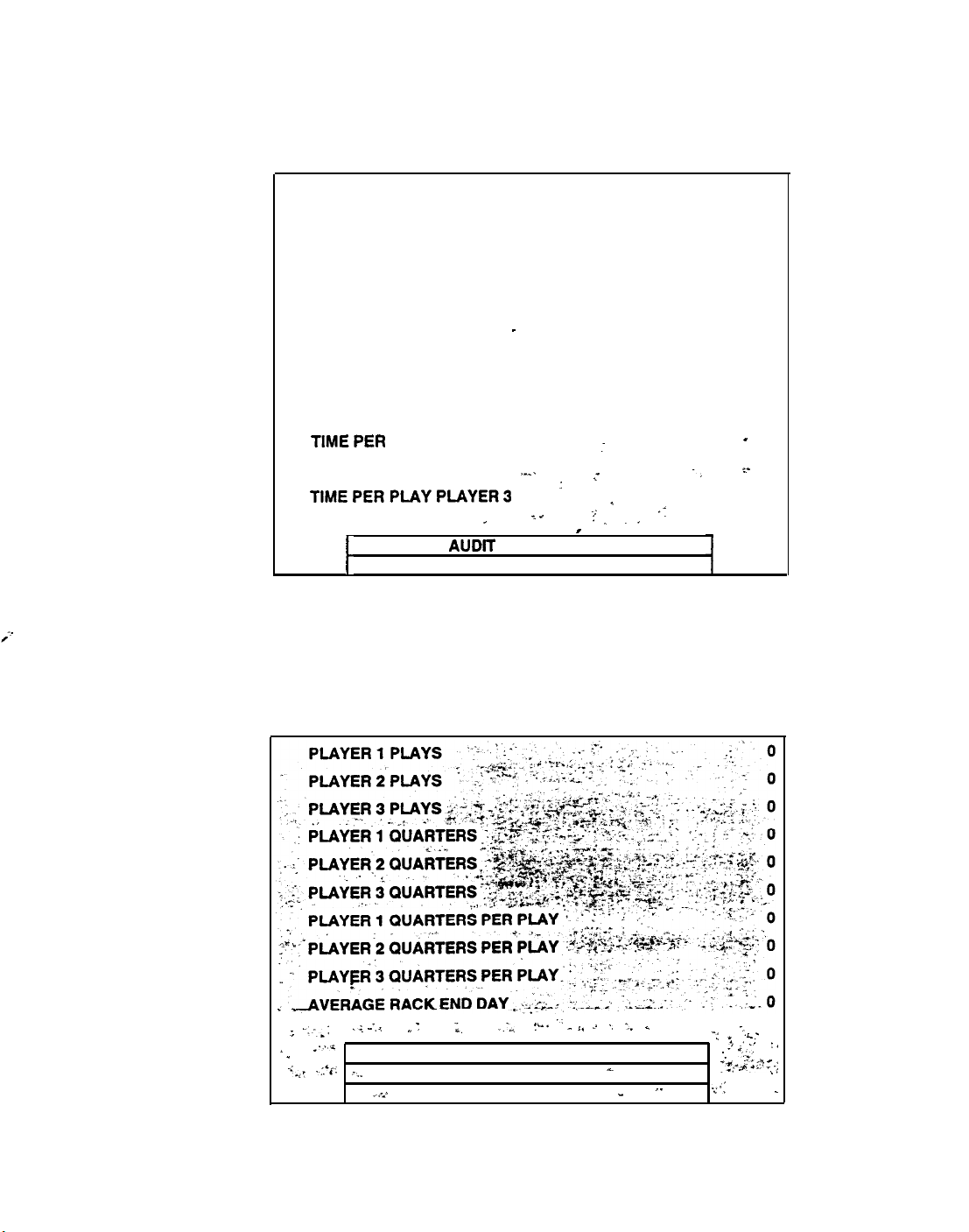
GAME AUDITS
The Game Audits Menus permit the operator to review the game play statistics. Additional menus give
detailed reports for each player position on game starts, ends, cabinet abuse, fault conditions, etc.
Highlight Game Audits by using any joystick to select the option; then press any control panel button to
activate. Choose Next or Previous Page to review all of the audits in the game.
0
-
0
-
0
0
0
0
0
0
0
0
0
0
GAMES STARTED
TOTAL GAME PLAY TIME
TOTAL GAME UP TIME
TOTAL TIME PLAYER 1
TOTAL TIME PLAYER 2
TOTAL TIME PLAYER 3
-
TIME PER QUARTER PLAYER 1
TIME PER QUARTER PLAYER 2
TIME PER QUARTER PLAYER 3
TIMEPER
TIME PER PLAY PLAYER2
TlMEPERPLAYPLAYER3
PLAY PLAYER1
: ~
r
NEXT
AUDlT
PAGE
t
RETURN TO MAIN MENU
.__.
: +
.~
;
;;
._ .,
I
-,
_
‘.
AUDIT MENU PAGE 1
These screens report information but do not permit changes to be’ made. Select Next Audit Page to view
additional game statistics reports.
Use the joystick and action buttons to move between Audit menus or to return to the main menu.
; -.-,:
L
.
.i*.,
:
;,
--.
1
.1
*.,a
.:.‘c
i,_
”
NEXT AUDlT PAGE
PREVIOUS AUDlT PAGE
---.a
RETURN TO MAIN MENU
_-_,,
‘.
f‘-. ^
‘*
J
‘, -_
%
._
‘.
-
“.
I i -,.
-5
_’ ..:
‘. 7,
,.~ .
__;Q.“‘..,
.;‘I
L
?
.:.,‘i _,
,
.,
-
AUDIT MENU PAGE 2
1-18
Page 20

GAME AUDITS (continued)
Highlight Game Audits by using any joystick to select the option; then press any control panel button to
activate. Choose Next or Previous Page to review all of the audits in the game.
GAME END IN RACKS
GAME END IN RACKS
GAME END IN RACKS
GAME END IN RACKS
GAiE
BfiD
i+J
RACKS
GAME END IN RACKS
GAME END IN RACKS 61-70
GAME END IN RACKS
GAME END IN RACKS
l-10
11-20
21-30
31-40
a__5@- ~~
51-60
71-60
61-90
:
..
GAME END IN RACKS 90-100
GAME END IN RACKS 101-l 10
GAME END IN RACKS 111-120 ~.
GAME
,.. .
ENDIN
RACKS121-130
_.
.
&XT
AUDIT PAGE
PREVIOUS AUDIT PAGE
‘:--1
_.I_”
.’
RETURN TO MAIN MENU
AUDIT MENU PAGE 3
,’
-
_
,%, x. a.. .-
,+-
, .
0
0
0
0
0
0
0
0
0
0
0
0
0
A Rack constitutes one finished adventure. The game is over when the time or number of lives is zero.
Player learning curves can be assessed by tracking how many racks are completed before games end.
These screens report information but do not permit changes to be made. Select Next Audit Page to view
additional game statistics reports. Choose Previous Audit Page to return to the earlier screens.
.:
.Y’
PREVIOUS
‘.
RETURN TO MAIN MENU
AUDfl PAGE
AUDIT MENU PAGE 4
-‘G.’
.cl:-.
$.a
“__
1-19
Page 21

PRICING OPTIONS
The Pricing Options menus allow the operator to view current settings or change the cost of games.
Custom pricing allows the operator to select the specific number of coins or credits required for each
game. Factory default values are restored if the CPU Board is exchanged or the back up battery fails.
Use the joysticks to select a particular game option. Joysticks are also used to view the range of choices
and change values. Options may be reset to factory defaults or changed after each viewing.
We recommend that all pricing options be examined and recorded before any changes are made.
STANDARD PRICING
CUSTOM MULTIPLIERS
CUSTOM PRICING
FREE PLAY
CREDlTS
FOR FULL GAME
RETURN TO MAIN MENU
PRICING OPTIONS SUB MENU
An additional box appears on screen to explain the functions available as each item is selected.
:
- m_,*
. .
e.
,.
-
-
,. /., *.
1.. s,. 1 .y s2-*. ._ &- .“..
.25 .25
DIPSWITCH
.2 T6
START I 2 i0 CONTINUE
. . 1
CREDIT/ 1 COIN
-. :
‘SK
*.
-BILL
51.00
:?
‘- .‘. ‘.
STANDARD PRICING SUB MENU
Standard Pricing is adjusted by changing Dip Switch positions. The display shows the current settings.
No price will appear if the device is not active. S3 and S4 are not active in the menu example above.
’ ,
- -
.
:_
CHUTE
i
I
‘,.
~
- (
VAUDATOR MULTIPLIER: : -
4
MULnPLIER:
”
‘1
-
;&
::-
I_
1 :,
1
’
‘5:.
.l...
.:
CUSTOM MULTIPLIERS SUB MENU
Custom Multipliers reports values used to calculate earnings. Current values are displayed on screen.
Changes to multipliers will affect the reports on the Detailed Data menu under Coin Bookkeeping.
l-20
Page 22
PRICING OPTIONS (continued)
PRICING:
FREE PLAY:
MAXIMUM CREDITS:
CREDITS TO START:
CREDITS TO CONTINUE:
CUSTOM PRICING
Custom Pricing shows credit requirements and maximum limits. The present settings are displayed.
The range of adjustment for credits is 5 through 99.
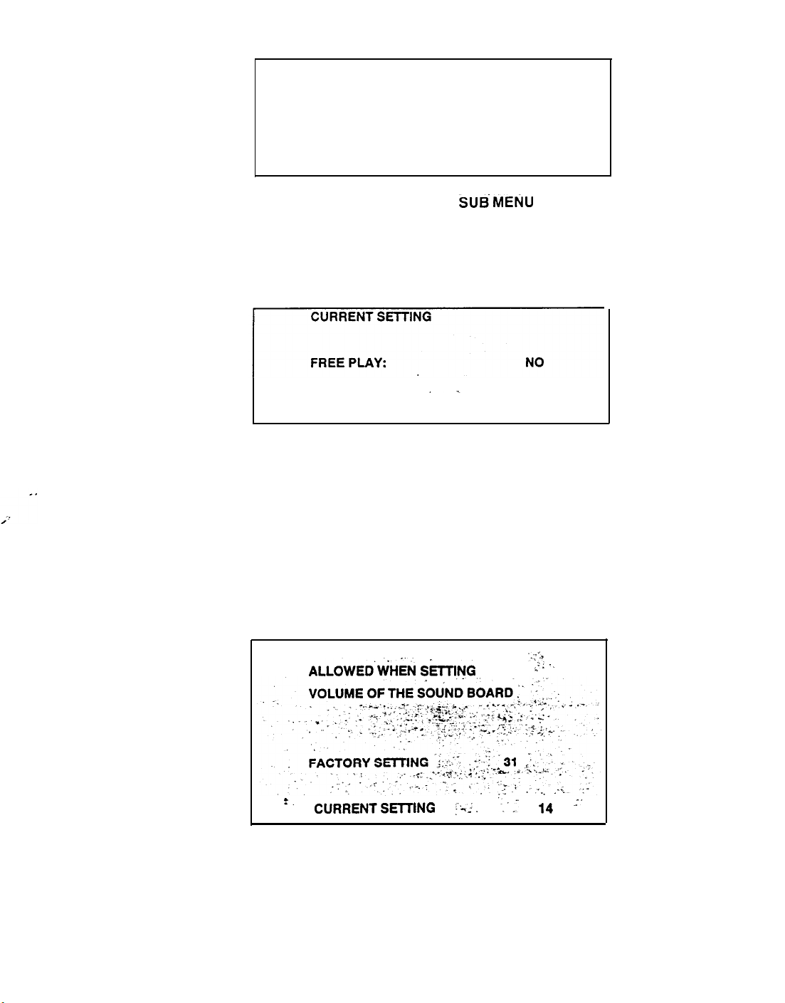
FREE PLAY SUB MENU
DIPSWITCH
NO
50
1
1
SUBS MENU
Free Play affects several game variables at one time. Only one item shows on some report or adjustment
menus when Free Play is enabled (for example, no credits are required to start or continue a free game).
GAME ADJUSTMENTS
The Game Adjustment menu items allow the operator to customize the game sound level to match the
environment. Higher sound levels generally attract more attention from potential players.
Highlight setting choice with any joystick, then press any button to lock setting.
THIS IS THE MINIMUM LEVEL
ALLOWEDiiHiN ShNG
‘. CUBPENTSET-DNG ;:-. ‘:_= 14
GAME ADJUSTMENT SUB MENU
The minimum level can be set between zero and half power (range 0 through 128).
.
THE
-_-,:’
.
:,” ”
-’
NOTE: These adjustments affect the volume of the tests as well as the game play.
1-21
Page 23
UTILITIES
The Utilities Menu allows the operator to clear individual memory counters or to reset them all at one time.
Use the joysticks to select a particular game option. Joysticks are also used to view the range of choices
and change values. Options may be reset to factory defaults or changed after each viewing.
CLEAR CREDITS
CLEAR COIN COUNTERS
CLEAR GAME AUDITS
RESET HIGH SCORES
DEFAULT ADJUSTMENTS
FULL FACTORY RESTORE
RETURN TO MAIN MENU
UTILITY SUB MENU
Clear Credits removes any posted credits from the game. It does not affect any other game items.
Clear Coin Counters removes any paid credits total and sets all coin slot counts to zero.
Clear Game Audits changes all game play statistics back to zero.
Reset High Scores returns the high score table to the factory default values.
. .
Default Adjustments returns all game adjustments to the factory default values.
I”
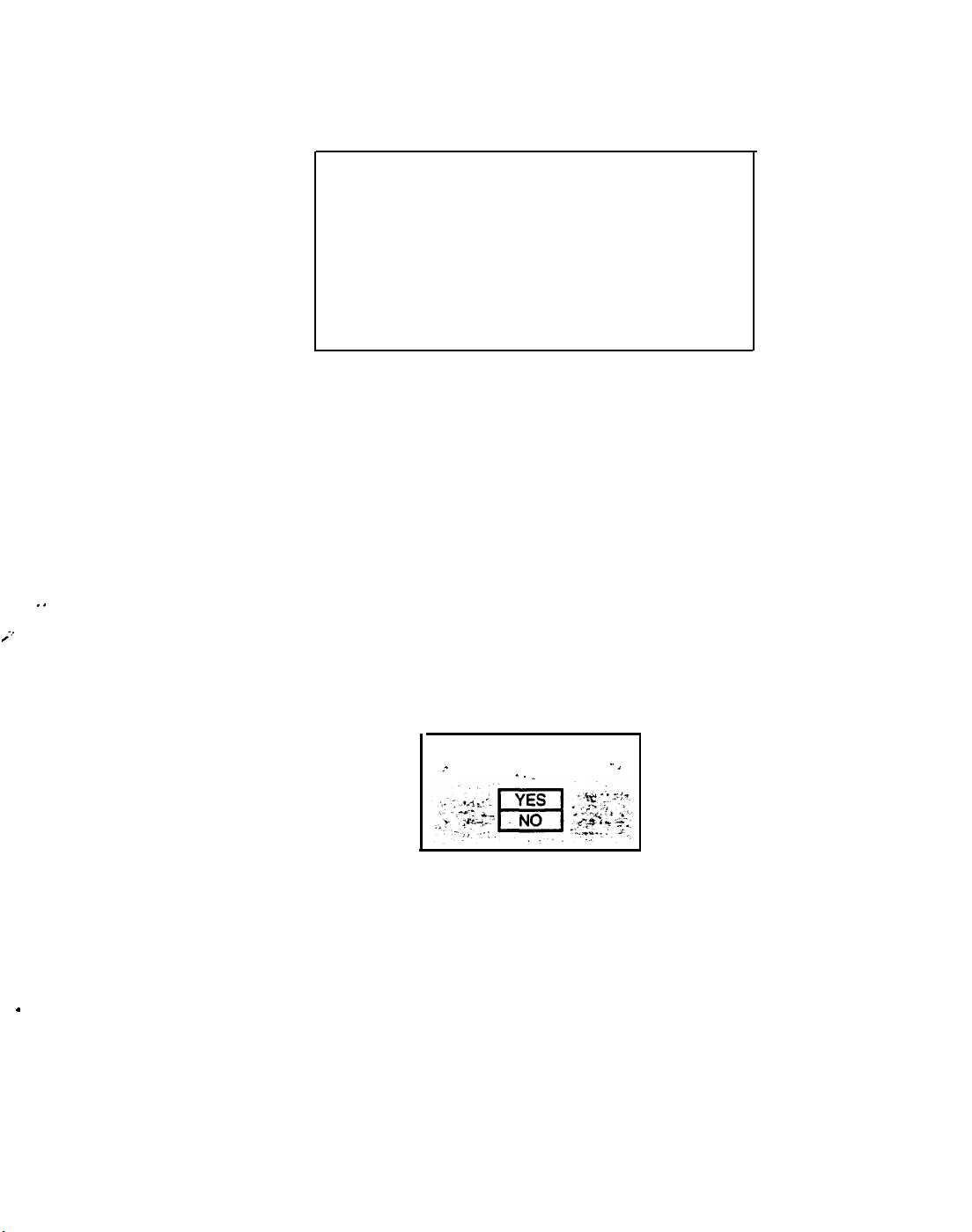
Full Factory Restore changes all categories to the factory default values simultaneously.
After an item has been selected, you are given the opportunity to escape from this change. For example:
CLEAR CREDITS?
_
ARE YOU SURE?. _
-. .
.
LAST CHANCE SUB MENU
Once any clear function has been selected and verified, the values are reset and can not be restored.
We recommend that all utility values be examined and recorded before any changes are made.
.
l-22
Page 24
HARDWARE INFO
Displays the unit type, serial number, and date and location of manufacture.
This information will be
requested each time the operator requests parts, service, upgrades, etc.
MIDWAY GAMES INC.
XX UNIT
SERIAL NUMBER:
DATE OF MANUFACTURE: MONTH, DAY, YEAR
PRESS ANY BUTTON TO QUIT
HARDWARE INFORMATION MENU
This screen reports information but does not permit changes to be made. Press any button to quit.
The Title line identifies the manufacturer of this game.
The Unit line is a code which describes the electronic board set used in this product.
Serial Number and Date of Manufacture identify the game production run.
VOLUME ADJUST
Music plays continuously with this screen. Use any joystick or the volume buttons to change the sound
level of the game. Press any control panel button to save the volume level and return to the Main Menu.
VOLUME ADJUST MENU
The maximum level can be set between minimum and full power (range 31 through 255). Minimum level
can be changed under Game Adjustments. Loud games attract more player interest than low levels.
NOTE: These adjustments affect the volume of the tests as well as the game play. If the volume
levels are set to minimum (zero), there will be no sounds from the speakers during any of the
audio tests. It is recommended that the volume levels be set to a moderately high value each time
the sound portion of the game or the speakers are checked. The levels may be returned to their
previous settings after the tests have been completed.
l-23
Page 25
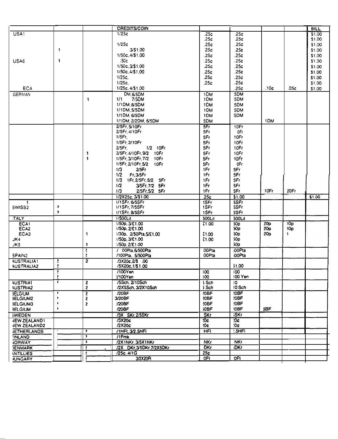
STANDARD PRICING TABLE
NA ME
USA1
USA2
USA3
USAJ
USA5
USA6
USA7
USA8
USA9
USA10
USA
ECA
GERhMN 1
GERMAN2
GERMAN3
GERMAN4
GERMANS
GERMAN ECA
FRANCE1
FRANCE2
FRANCE3
FRANCE4
FRANCE5
FRANCE6
FRANCE7
FRANCES
FRANCE9
FRANCE10
FRANCE1 1
FRANCE12
FRANCE ECA
CA NADA
SWISS
1
SWISS2
SWISS3
,TALY
JK ECAl
JK
EC%!
JK
ECAJ
JKJ
JKS
SPAIN 1
SPAIN2
4USTRALIAl
9USTRALIA2
JAPAN 1
JAPAN2
4USTRIA
1
WSTRIA2
3ELGIUM
1
3ELGIUM2
3ELGlUM3
3ELGlUM
ECA
jWEDEN
IEW
ZEALAND1
START
2
2
1
1
2
1
1
2
3
3
3
2
2
2
2
2
2
2
2
2
2
2
2
2
2
2
2
2
2
2
2
2
>
>
I
,
1
,
CONTINUE
2
1
1
1
1
1
1
2
2
3
3
2
1
1
1
1
2
2
1
1
1
1
1
1
1
1
1
1
1
2
2
2
2
2
2
1
1
1
1
1
2
1
I
I
1
I
,
b
CREOllSlCOlN
1;25c
112%
1125~
l/MC,
lI5cc. 461 .W
1
:soc
115oc.
YSl .W
1/5Oc. .vSl .w
1125c.
4151.00
112%.
461.00
lI25C. 461.00
111
OM. 6iSDM
111
Oiu.
1IlDM.
1IlOM.
1IlDM.
IlloM; 212OM.6J5OM
26Fr.
YlOFr
Z’5Fr. 4/tOFr
115Fr.
YlOFr
1ISFr.
ZtOFr
USFr.
YlOFr. 1
USFr. 4IlOFr. 9Q
lI5Fr. YlOFr. 7R X
l/SFr. 2/10Fr.
Ii3
X 1 Fr.
1R
X 1
I13
X
lfr. ZSFr. M
Ii2
X 1 Fr. YSFr.
l/3
X 1 Fr.
112X2%.
IIlSFr.
IIlSFr. 76SFr
IIlSFr.
IlMoLlt
I/5@.
Yf1.W
IMJp.
2x1.00
b3Co.
IBOP. 3x1.00
~/5cQ. 2/szl .w
/
1
OOFta.
11WPti
13xzoc. 26
ISX2oc.
/lOoYen
!I1
WYen
/SSch. 2/lOSch
RXSSch. 3iZXlOSch
12OBF
QOBF
i208F
13X
1
SKr. 2/5SKr
/3XZOC
RXZOc
ItHFI. 36?.5HFI
ItFmk
PLXlNKr.
12X
1
.
DKr.
i25c. 4/1G
RX
1 Oft.
361.00
7i5DM
9i5Dh4
5/SOM
6/5OM
l/2
5Q X
2/SFr
Fr.
YSFr
215Fr. M
361.00
6/5SFr
86SFr
26QPla.
yC1.W
6/500Ffa
YSOORa
1
.w
r/S
1
.I0
YSXlNKr
YSDKr,
3RX2OFt
X
1OFr
X
1OFr
1OFr
1OFr
X
5Fr
712
X
SFr
X
5Fr
712XSDKr
COIN 1
.25c
.25c .25c
.25c
25~
.25c .25c
.25c
.25c .25c
.25c .25c
.25c .25c
.25c
sl.w
1OM
1OM 5OM
1OM
1OM 5OM
1DM
5OM
5Fr
5Fr
5Fr
5Fr
5Fr
SFr
5Fr
5Fr
1Fr
1Fr
1Fr
tFr
tFr
.25c 51.00
1
SFr
1SFr 5SFr
1SFr
5WLll
il.00
il.00
il .w
il.00
it.00
WPta
WPta
2oc
2oc
100
Yen
100
Yen
jSch
jSch
!OBF !OBF
MBF
!OBF !OBF
ioBF
I
SKr
!&
!OC
‘HFI
Fmk Fmk
NKr
OKr
25c
OFt
COIN 2
.25c
.25c
.25c
.25c
,250
.25c
5DM
5DM
5DM
2DM
1OFr
1
OFr
1OFr
1OFr
1OFr
1OFr
1
OFr
1
OFr
5Fr
5Fr
5Fr
5Fr
5Fr
5SFr
5SFr
5OQLll
SP
NP
jop
5Op
=P
IOOPta
OOPta
El.00
91.00
100
IWYen
IO
Sch
IO Sch
!OBF
!OBF
iSKr
!oe
!OC
!.5HFI
NKr
IDKr
G
‘OFt
Yen
COIN 3
.lOC
1DM
1OFr
2%
2%
!Op
iSF
COIN4
.05c
!OFr
2
OP
l-24
Page 26

DIP SWITCHES AND JUMPERS
The CPU Board has a number of hardware variables which can be changed to adapt this assembly to
other uses. Jumpers determine which circuit paths are active, and DIP switches select instructions.
DIP Switches
There are two blocks of DIP Switches on this CPU Board set. Each block consists of ten individual
switches. Each switch enables or disables one program instruction (refer to DIP Switch Test).
All
instruction
variables
thir n~rn~
to
LIIl..l yu”” UI” U”II..UIU ..I
PTP
cnftwzara cdec!a&
frDv
thn
Mensa arctern
I
L,,”
ll,Yll” V,U.U”” _U” I “I .I,”
Far-b
nf
the D!p
r
Switches should be set to its OFF position (Factory default) for the program to operate properly.
Jumpers
The active circuit paths have been optimized at the factory during the board test procedure. Each of the
jumpers should be left in its original position to avoid program error messages.
NOTES
l-25
Page 27

RAMPAGE
WORLD TOUR
SECTION
TM
TWO
PARTS
Warning
USE OF NON-MIDWAY PARTS OR CIRCUIT MODIFICATIONS MAY CAUSE SERIOUS INJURY OR EQUIPMENT
DAMAGE! USE ONLY MIDWAY AUTHORIZED PARTS.
.
For safety and reliability, substitute parts and modifications are not recommended.
.
Substitute parts or modifications may void FCC type acceptance.
Page 28

MS.
a-32x3/a
4oaa-oi 113-o_
PL-HWH (4)
f-i
h
Fluorescent Lamp Assembly
/
Monitor
A-20277
Fluorescerli hlb, 15w
-1 I>_,.,.
hlounting
tlreckets
t/*-z0
4420-01141-00
(4)
mange
Crlp
Page 29

CABINET
FRONT
-
VIEW 2
Screened
On/Off Switch
Slarquee
I
Screw, H-F
4608-01081-11
/
#8x11/16
PL-HWH
Marquee Retainer
03-8252-X
/
03-9373-
1
8 Ohm Speaker
5555-13961-00
Nut. 6-32
4406-01128-00
Speaker Grille
01-11859
Screw,
#8x5/8
4108-01193-108
KEPS
TRX-TR
‘-
/-I/./.
Bolt, 8-32x l-
4308-01123-208
1/4CB
(5)
nl
CPU Board
(see detailed diagram)
Coin Door with Lock
(see Application Chart)
Cash
Door with Lock
.
Associated
Parts Not Shown:
Glass Retainer
Leg Leveler
Screened Marquee
Glass Retain
Brkt.
grkt
Screws
Control Panel
(see detailed diagram)
2-3
Page 30

CABINET REAR VIEW
Flange Grip
41-00
Handle Pull Vent
03-8326
01-11286
Screw,
Bolt,
Screw,
,
H-F
4608-01081-11
1/4-20x1 - l/4
4320-O
SMS ,#Sx
4108-01115-20B
#8x11/16
1123-20B
1
-l/4
PL-HWH
CB
PL-HWH-A
Leg Leveler
38-7377
2-4
Page 31

H-F
@i--32x1
4606-01061-11
*Door Lock Cam
l/16 PL-HWH
*Door Lock Cam
REAR DOOR PARTS
Upper Door Lock Cam
01-8969
Nut.
l/4-20
4420-01141-00
Complete Rear Door Assembly A-20281
Flange Grip
*Secondary Door Cam Lock
*Primary
Bolt
20-6542-TB
Door Cam Lock
20-10167
1/4-20x1-1/4
4320-01123-208
Rear Wo od Door
04-10149.1
Bolt.
1/4-20x1-1/4
4320-01123-208
COIN COLLECTION PARTS
Chute Bracket
01-I
1334
Bolt
1/4-20x1-1/4
4320-01123-20B
Coin Chute
CB
*Door Lock
CB
Cam
&
Coin Meter
Diode
5580-13476-00
2-5
Nut
l/4-20
Flange Grip
4420-01141-00
Screw MS
4004-01041-06
Screw SMS
4110-01088-12
4-40x3/8
#10x3/4
P-FLH
SL-HWH
Cash Tub
03-8863
Page 32
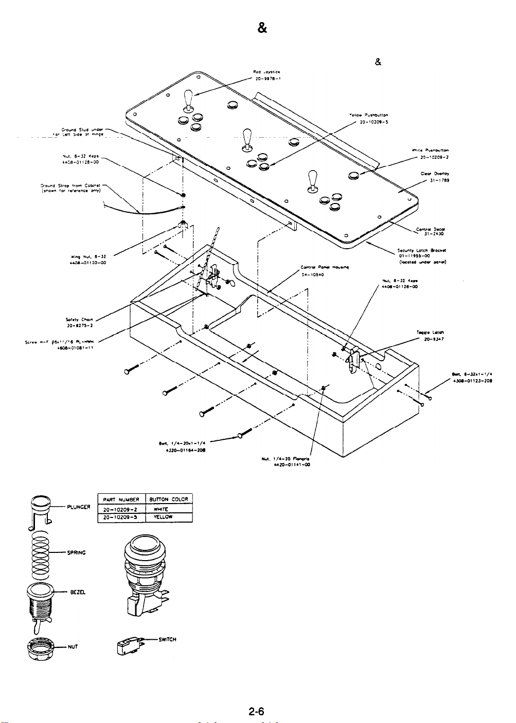
CONTROL PANEL & HOUSING PARTS
Complete Control Panel
L?
Housing Assembly A-21091
PUSHBUTTON DETAIL
PWNCER
SPRING
2-6
Page 33
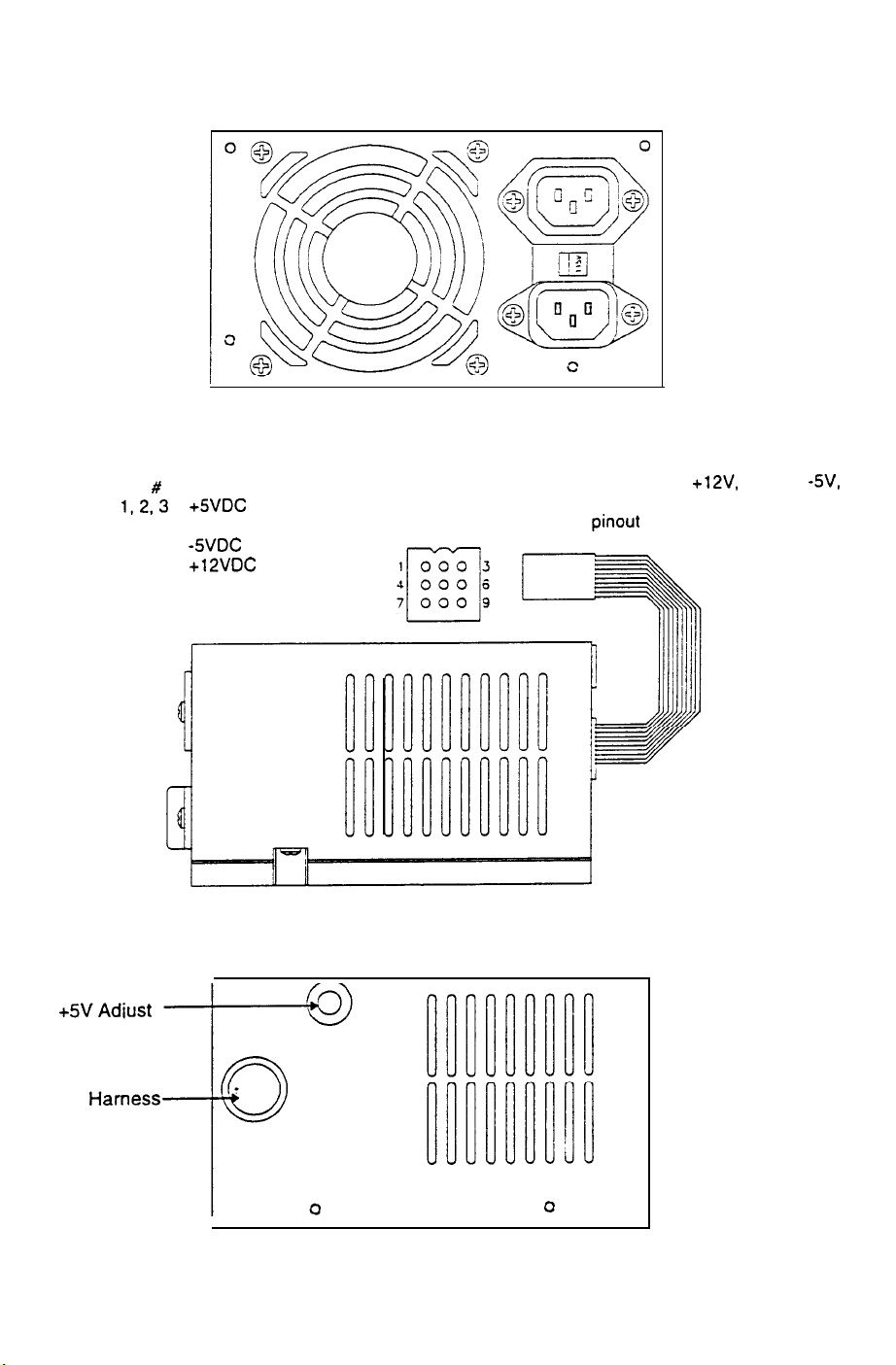
POWER SUPPLY
20-10167
REAR VIEW
Connector Pin Designation
Function Wire Color
#
Pin
1,2,3
4. 5, 6
7
6
9
+%/DC
Ground
-5VDC
+12VDC
-12VDC
Red
Black
Yellow’
Orange’
Blue’
SIDE VIEW
‘Note: Many
supplies use yellow for
and white for -12V. This is acceptable as
long as the
computer grade power
+12V,
blue for
pinout is correct.
-5V,
FRONT VIEW
2-7
Page 34

CPU BOARD ASSEMBLY
A-21 907
n
+
.
0
“ii
/
..
**
Ul
. .
;;
8.
::
i
-
26
::
::
:I:
‘I’
::
::
::
:I: UI
22
Ul I8 :/:
:I:
::
.I#
I*
1
:,:
u121::
r. -
Ii ,,,..ili
*
:
:
; U2 :: u3 :: u4 *I us
:
i ..*
l---n-n
~1i
i iii ; i ij;
.::
::
::
,
::
II
. .
.I
::
I.
::
::
::
::
::
::
I
::
::
I
i;
.
:
:
~~
: ~132;: Ulz8;: Ul24 :: Ul20 ;; Ullb;; U112;; UIae~. UlaI
’
:
:
:
u133;:u129 ;; u12s;;
i
II.
:/:
I,.
**
::
::
!
::
u117:; u113::
UI
I a iii
Il. -
*I.
UI
06
iiiUt 02 ~
::
:I:
I
::
::
::
::
I
2-8
Page 35
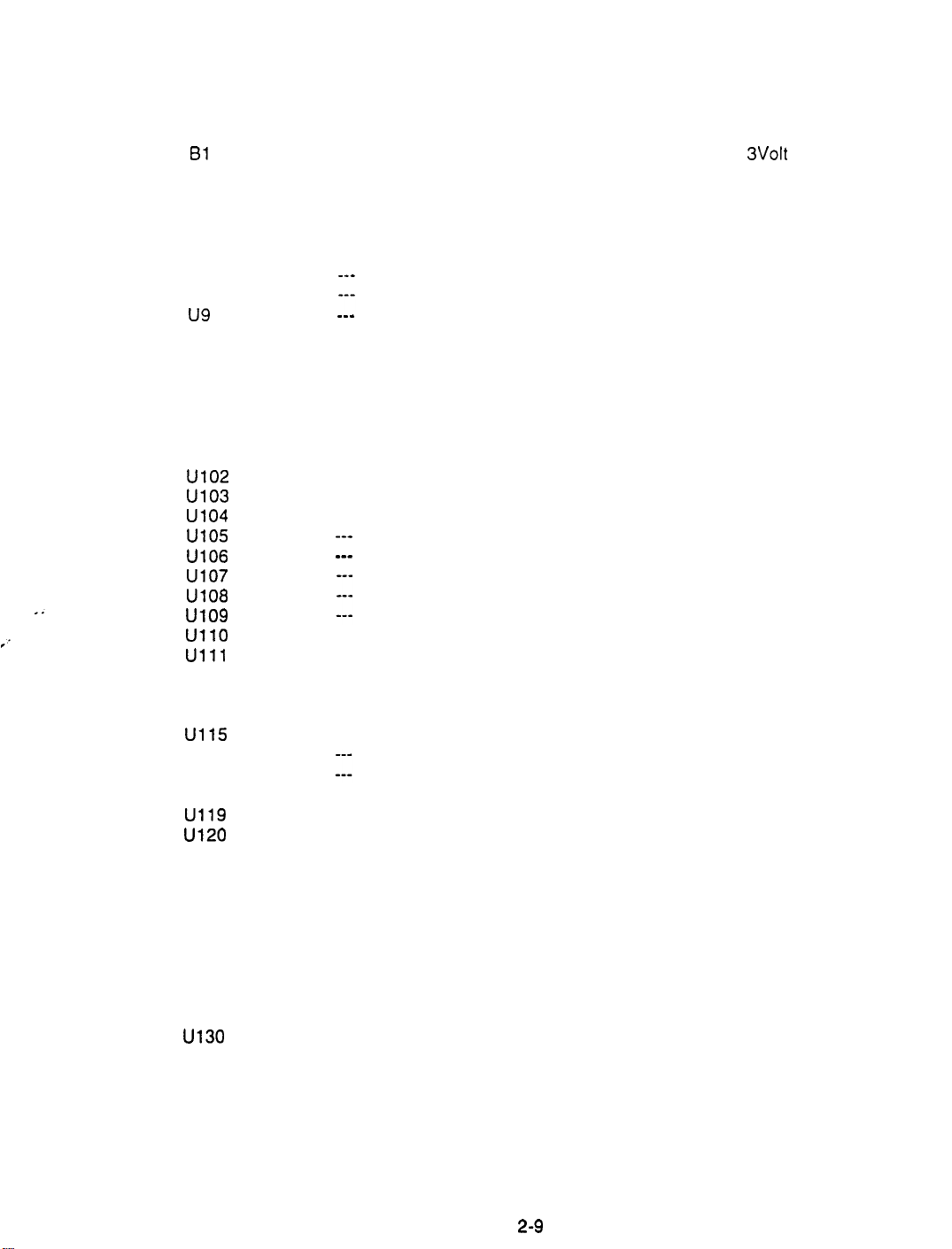
CPU BOARD ASSEMBLY
Field Replaceable Parts
DESIGNATION
61
u2
u3
u4
u5
U6
u7
U8
u9
u35
u45
u47
u54
u57
U63
U64
u102
u103
u104
u105
U106
u107
U108
u109
UllO
Ulll
u112
u113
u114
u115
U116
u117
U118
u119
u120
u121
u122
U123
U124
U125
U126
U127
U128
u129
u130
u131
U132
u133
PART NUMBER
5880-l 1056-00
A-5343-40065-2
A-5343-40065-3
A-5343-40065-4
A-5343-40065-5
___
___
___
A-20257
A-20258
A-20259
A-5343-40065-22
A-20255
A-5343-40065-23
___
___
___
___
--a
_--
A-5343-40065-27
A-5343-40065-26
A-5343-40065-25
A-5343-40065-24
___
___
A-5343-40065-31
A-5343-40065-30
A-5343-40065-29
A-5343-40065-28
A-5343-40065-1 0
A-5343-40065-1 1
A-5343-40065-1 2
A-5343-40065-1 3
A-5343-40065-1 4
A-5343-40065-1 5
A-5343-40065-1 6
A-5343-40065-1 7
A-5343-40065-1 8
A-5343-40065-1 9
A-5343-40065-20
A-5343-40065-21
FUNCTION
Memory Backup
Sounds
Sounds
Sounds
Sounds
None
None
None
None
Game Instructions
Game Instructions
Game Instructions
Game Instructions
Sound Instructions
Game Instructions
None
None
None
None
None
None
None
None
None
Images
Images
Images
Images
None
None
None
None
Images
Images
Images
Images
Images
Images
Images
Images
Images
Images
Images
Images
Images
Images
Images
Images
DESCRIPTION
3Volt
Lithium Battery
EPROM Assembly
EPROM Assembly
EPROM Assembly
EPROM Assembly
Not used at this time
Not used at this time
Not used at this time
Not used at this time
FPGA Assembly
FPGA Assembly
FPGA Assembly
EPROM Assembly
PLD Assembly
EPROM Assembly
Not used at this time
Not used at this time
Not used at this time
Not used at this time
Not used at this time
Not used at this time
Not used at this time
Not used at this time
Not used at this time
EPROM Assembly
EPROM Assembly
EPROM Assembly
EPROM Assembly
Not used at this time
Not used at this time
Not used at this time
Not used at this time
EPROM Assembly
EPROM Assembly
EPROM Assembly
EPROM Assembly
EPROM Assembly
EPROM Assembly
EPROM Assembly
EPROM Assembly
EPROM Assembly
EPROM Assembly
EPROM Assembly
EPROM Assembly
EPROM Assembly
EPROM Assembly
EPROM Assembly
EPROM Assembly
2-9
Page 36
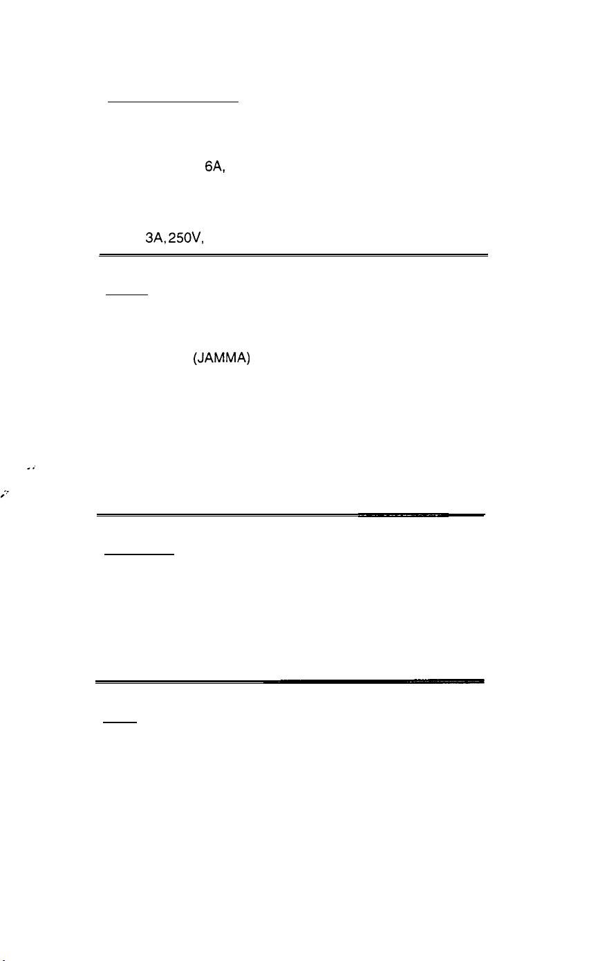
Other Parts Necessary
Power and Protection
A.C. Distribution Assembly
A.C. Power Chassis
6A,
A.C. Line Filter,
D.C. Switcher Power Supply
Fuse Holder Panel
3A, 25OV,
Fuse,
Cables
Dixie-Mars Adapter Cable
USA DBV Acceptor Cable
Main Harness
AC Distribution Cable
Line Voltage Cable Assembly
Speaker Assembly Cable
Fluorescent Lamp Cable
Control Panel Cable
IDC A.C. Cable
250V
SB 5731-l 0356-00
(JAMMA)
Cable
A-20278
04-10103.1
5102-l 4240-00
20-10167
5733-l 2869-00
H-17019
H-20398
H-20282.1
H-20279
A-20331
H-l 9599
H-20330
H-21 665
H-20353
Documents
Product Registration Card
DBV Installation Instructions
Game Manual
Product Safety Manual
Tools
T-20 Torx key
16-9478.2
16-9637
16-40065-l 01
16-10341
20-9620
2-10
Page 37
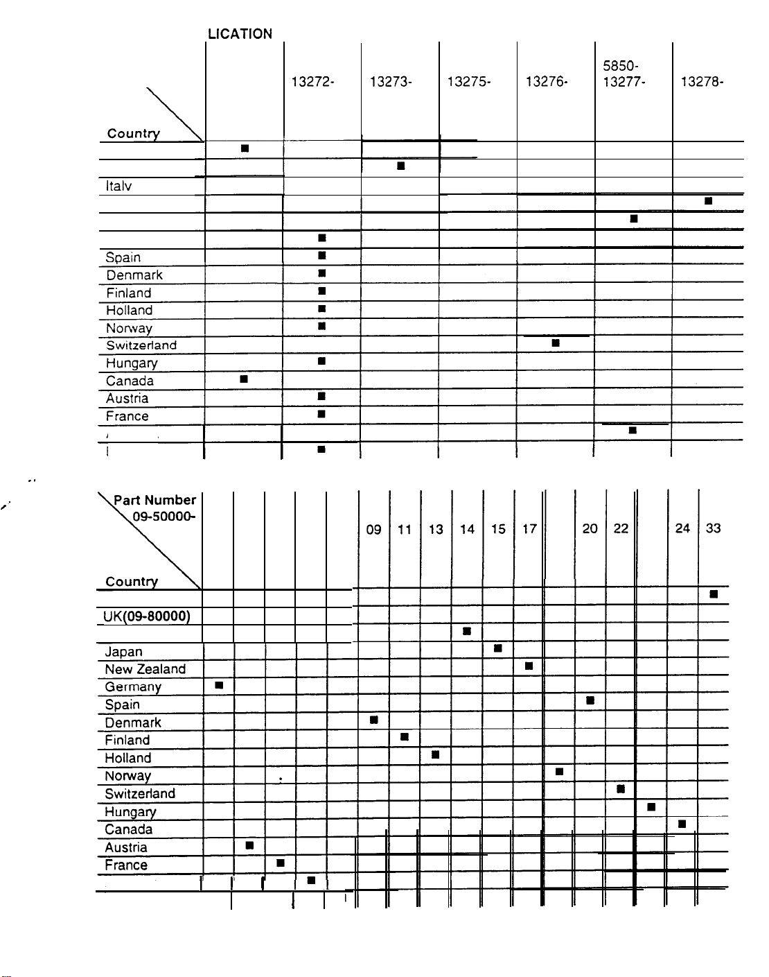
LINE CORD AP
Part Number
\
USA
UK
ltalv
Japan
New Zealand
Germany
SDain
Australia
Belgium
LIGATION CHART
5850-
13271-
00
5850-
13272- 13273- 13275-
00 00 00
5850-
5850-
5850- 5850-
13276-
13277-
00 00
n
5850-
13278-
00
. .
/’
COIN DOOR APPLICATION CHART
02 03 04 06 07
18
23
USA
UK(09-80000)
Italy
Australia
Belgium
I I
I
I
n
2-11
Page 38
RAMPAGE
WORLD TOUR
SECTION
THREE
TM
WIRING
Warning
Failure to reconnect all ground wires or replace metal shields and covers with each mounting screw installed and
securely tightened may result in radio frequency interference.
3-l
Page 39

JAMMA
Chart
Not Used
Control Panel wires that are not part of the Main JAMMA Harness.
D.C. Power Source Voltage Limits
3-2
Page 40
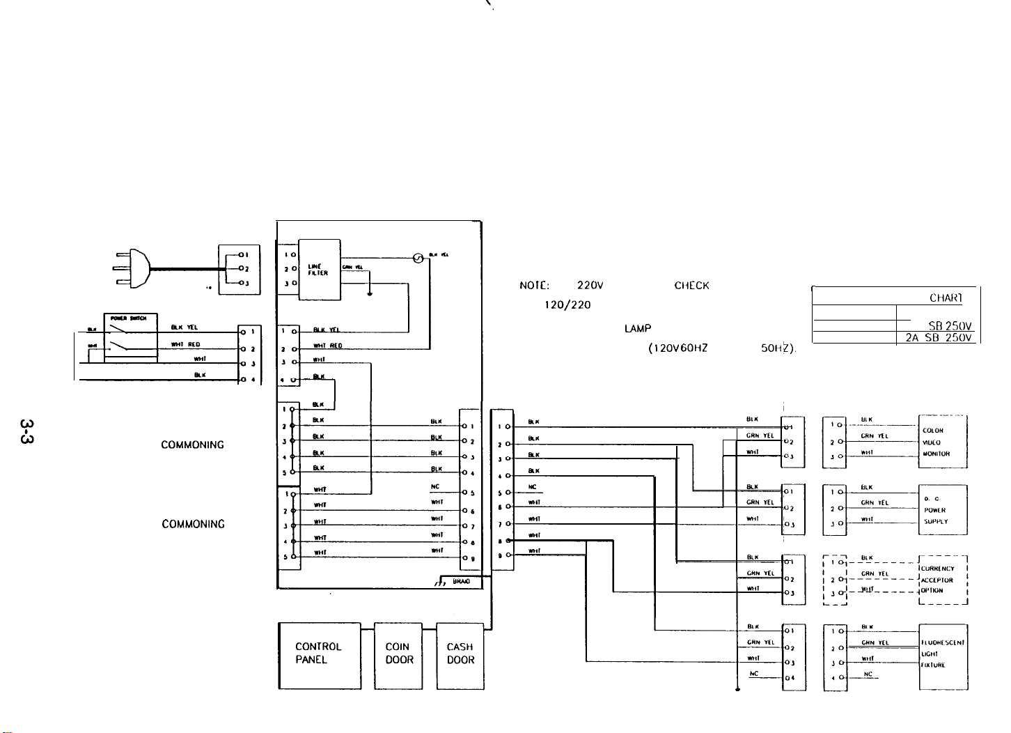
POWER WIRING DIAGRAM
A. C. POWER CHASSIS
COMMONING
COMMONING
BLOCK
BLOCK
NOIE:
FOR
22DV
OPERATION
AND
120/220
THE FLUORESCENT
CHANCED IF NEEDED
SWITCH ON POWER SUPPLY.
LAMP ASSEMBLY MUST BE
CliECK
(12OV
GOHZ OR 220V
FUSE RATING
50~;I).
r
FUSE APPLICATION
LINE VOLTAGE FUSE RATING
120 3A SB
220
CHAR1
2A SB 250’4
25OV
Page 41

CABINET WIRING DIAGRAM
3-4
Page 42

RAMPAGE
WORLD TOUR
TM
SECTION
FOUR
,:
TROUBLESHOOTING
This game uses complex electronic components that are very SENSITIVE to static electricity.
The following precautions must be observed and followed prior to handling any of the game
electronics.
1.
Ensure that the A.C. power to the game is turned OFF prior to servicing the electronics.
2.
Discharge any static electricity build up in your body by touching the safety ground stud of
the power supply chassis while the line cord is connected to a properly grounded outlet.
This is to be done BEFORE touching or handling the electronic assemblies.
Store the electronic assemblies in an anti-static area. Anti-static bags are to be used to
3.
store or transport the game CPU Board Assembly.
DO NOT remove or connect any electronic assemblies when the cabinet power is ON.
4.
Doing so will damage the electronic assemblies and void the warranty.
Always replace ground wires, shields, safety covers, etc. when maintenance or service is
5.
completed. Ensure that all ground and mounting screws are installed and tightened firmly.
4-1
Page 43

GAME DOES NOT START
1.
Game appears completely non-functional; no audio, no illumination, no video display.
A:
Check that the Power Switch has been turned ON (top left rear
B:
Turn OFF the game power. Unplug the A.C. line cord. Unlock and remove the cabinet rear door.
The Power Supply Line Voltage Switch must be set to agree with the local A.C. line voltage.
C: Remove the Line Cord Cover Plate. Test the line cord, power plug and I.E.C. connector for
~~ ~~ ~~ea~sdr~~~~age.~~
into the mating receptacle of the cabinet. Replace the cover plate and all four screws.
D: Ensure that cabinet wiring harness connectors are fully seated in the corresponding A.C. Power
Chassis Assembly connectors (refer to Power Wiring Diagram, Section Three).
E: Examine the A.C. Line Fuse on the A.C. Power Chassis. If the fuse is faulty, replace it with an
identical fuse from the spare parts bag. Replace the spare fuse when repairs are complete.
F: Fully seat the A.C. plug in the outlet. Verify that A.C. line voltage is present. Turn the game
power ON. Check the D.C. wiring harness and connectors if the fuse opens the circuit again.
2:
Video game appears non-functional, but currency acceptor price indicator is illuminated.
A:
Unlock and open the coin door. Inspect the CPU Board Assembly under low light level conditions.
A glow will be seen from the Light Emitting Diodes if there is voltage in the processor circuits.
This does not mean that voltages or signals are as they should be, but it does indicate that the
CPU Board is receiving some D.C. power from the Power Supply.
Verify
the~conf?uify~of
each
w7rei-n the--cord.-
cornerof
the game cabinet).
Fuiiy seat the
i.E.2.
connector
8:
Turn OFF the game power, Unlock, open and remove the rear door. Inspect the CPU Board
Assembly. Ensure that the
mating board connector. Check the other wiring harness connectors in the same way.
CAUTION: DO NOT REMOVE OR INSTALL ANY CONNECTOR WHEN POWER IS TURNED ON.
DOING SO WILL DAMAGE THE GAME CPU BOARD ASSEMBLY AND VOID THE WARRANTY.
C: Verify that the game CPU DIP Switches are set as intended. Refer to the DIP Switch
Configuration Chart (Section One) for variables and default settings.
D: Turn ON the game power. Using the 20 Volt D.C. setting on a digital voltmeter, measure D.C.
voltages present at the Power connector pins. Adjust the
the Cabinet Wiring Diagram (Section Three) for specific wiring information and voltage limits.
E:
Using the 2 Volt A.C. setting on a digital voltmeter, measure the same D.C. voltages as above.
Any reading here indicates that the supply voltages are unstable and may contain ripple or noise.
F: Verify that the
Note errors and/or failures found during these tests.
G: Enter the game Menu System by pressing and holding the BEGIN TEST switch inside the coin
door. Select DIAGNOSTIC TESTS from the Main menu. Once in the DIAGNOSTIC TEST menu,
choose MONITOR PATTERNS (refer to Section One for additional details). Use this set of tests
to check the operation of each screen used in the game.
game,runs and completes the power-up self-test sequence without any errors.
JAMMA Wire Harness connector is attached and fully seated onto the
+5V
source if it is necessary. Refer to
4-2
Page 44

GAME CAN NOT BE PLAYED
1.
Game will not accept currency or tokens and cannot be started. Audio and video are present.
Unlock and open the cash door. Empty the cash box.
A:
currency. Check the vault and remove any items that block the path from the mechanism.
Unlock and open the coin door. Check each Acceptor by hand to ensure proper mounting.
B:
Remove the mechanism and clear the currency path. Reinstall the mechanism and latch it.
Verify that the mechanism is level when the doors are closed. Repair or replace the coin door if it
c:
is bent or damaged. Adjust the cabinet leg levelers if necessary to keep mechanisms vertical.
2.
Game accepts currency or tokens, but does not start. Audio and video are present.
Unlock and open the coin door. Check each Acceptor by hand to ensure proper mounting. Verify
A:
that each of the release latches is in the closed and locked position. Test known good and bad
coins to see if the mechanism accepts and rejects the currency correctly.
Ensure that no loose parts or wires are caught in the hinges, latches, or switch contacts.
B:
Inspect to see if the external Acceptor indicators (Pricing, Flashing Arrows, etc.) are illuminated.
c:
Check connectors and cables for wiring continuity from CPU Board connectors to the Acceptors.
Enter the game Menu System by pressing and holding the BEGIN TEST switch inside the coin
D:
door. From the DIAGNOSTIC TESTS menu, choose the SWITCH TEST (refer to Section One for
additional details). Use these tests to confirm the operation of each switch used in the game.
Inspect the revenue for any counterfeit
Check for continuity in each of the suspect switch connections (Common to Normally Open or
I
E:
Common to Normally Closed). Replace faulty switches (bent levers, broken actuators, etc.).
Verify that each Acceptor is operating properly by placing it in a known good unit.
F:
3.
Player controls are intermittant or completely non-functional. Game starts normally.
Unlock and open the coin door.
A:
BEGIN TEST switch inside the coin door. From the DIAGNOSTIC TESTS menu, choose the
SWITCH TEST (refer to Section One for additional details). Use these tests to confirm the
operation of each switch used in the game.
Reach through the coin door and unlatch the control panel. Grip the joysticks and carefully tilt the
B:
panel back on its hinge. Ensure that no loose parts or wires are caught in the hinges, latches, or
switch contacts. Verify that the harness connectors are attached and fully seated.
Check that the cabinet wiring is correct for this game.
c:
connected to the control input wires from
Cabinet Wiring Diagram (Section Three) for specific wiring information.
Verify continuity in each of the switch connections (Common to Normally Open or Common to
D:
Normally Closed). Ensure that the control is operating properly by placing in a known good unit.
Enter the game Menu System by pressing and holding the
Ensure that the controls are properly
P9, PlO,
P12, and the JAMMA connector. Refer to the
4-3
Page 45

4. Game accepts currency or tokens, but number of credits per coin or bill is incorrect.
A: Unlock and open the coin door.
BEGIN TEST switch inside the coin door.
Enter the game Menu System by pressing and holding the
From the DIAGNOSTIC TESTS menu, choose the
SWITCH TEST (refer to Section One for additional details). Use these tests to confirm the
operation of each switch used in the game.
B: Check that the cabinet wiring is correct for this game.
switches are properly connected to the control input wires from
~~~ CO~R~C!QL Refer
to
theCabhet, Wiring~Biagram
(Section-Three) for specificwiring information.
Ensure that the coin meter and coin
P9,
PlO, P12, and the JAMMA
COIN SWITCH AND METER WIRING
FACTORY STANDARD
,CClN SWITCH
JAWMA
I
GROUND
1
o/
PIu
,6
/ I
JAMMA
PIN T
_
-
JAMMA
PIN 8
OPTIONAL WIRING
;..
COIN SWITCH 1
JAMMA
PIN 8
!!WRONG WAY!!
Do not connect the coin switches in this manner. This
circuit is INCORRECT, and will cause twice as many
credits per coin.
COIN SWITCH 1
JAMMA PIN 16
COIN SWITCH 2
JAMMA PIN T
GROUND
4-4
Page 46

AUDIO PROBLEMS
1:
Audio is non-functional, but video is present and game appears to operate normally.
A: Unlock and open the coin door. Enter the game Menu System by pressing and holding the
BEGIN TEST switch inside the coin door. From the Main menu, choose VOLUME ADJUST (refer
to Section One for additional details). Verify that the attract and game volume levels have not
been set at Zero. Change the levels if necessary to make the game audible.
B:
Follow the on-screen instructions to return to the first menu. Select DIAGNOSTIC TESTS from
the Main menu. Once in the DIAGNOSTIC TEST menu, choose SOUND
these tests to confirm the operation of each speaker in the cabinet.
C: Turn OFF the game power. Open the marquee and remove the glass. Inspect the speakers and
harness. Ensure that no loose parts or wires are caught in speaker cones, terminals, mounting
screws, or stuck to the magnets.
B’OARD
TEST. Use
D: Verify correct cabinet wiring for this game.
the audio output wires from the
Cabinet Wiring Diagram (Section Three) for specific wiring information.
E: Turn ON the game power. Using the 20 Volt D.C. setting on a digital voltmeter, measure D.C.
voltages present at the Power connector pins. Verify the
the Cabinet Wiring Diagram (Section Three) for specific wiring information and voltage limits.
F:
Using the 2 Volt A.C. setting on a digital voltmeter, measure the same D.C. voltages as above.
Any reading here indicates that the supply voltages are unstable and may contain ripple or noise.
G:
Verify proper operation of game CPU Board Assembly by placing it in a known good game.
2:
The audio is distorted, muff led or missing frequencies. A constant low hum may be present.
A:
Enter the game Menu System by pressing and holding the BEGIN TEST switch inside the coin
door. Select DIAGNOSTIC TESTS from the Main menu. Once in the DIAGNOSTIC TEST menu,
choose SOUND BOARD TEST. These tests will verify some of the functions of the audio circuits.
8: Turn OFF the game power. Open the marquee and check the speakers. This game uses coaxial
speakers, not discrete woofer and tweeter units. Ensure that each speaker is FULL RANGE (100
to 10,000 Hz response) and rated for at least 25
C:
Check that the speaker wiring is not reversed at one of the speakers. Weak low frequencies and
a thin or hollow sound quality is a symptom of incorrectly phased speakers. This condition may
not be detected by the SOUND TESTS, but it will be audible during normal game operation.
JAMMA connector. Verify speaker continuity. Refer to the
Ensure that the speakers are properly connected to
+SJ, -5V
WATTS.
and
+12V
sources. Refer to
D: Check that the cabinet wiring is correct for this game.
separate wires (not a common return) for each speaker. Ensure that all cabinet ground wires are
connected.
E:
Using the 2 Volt A.C. setting on a digital voltmeter, measure voltages at the speaker terminals.
Any reading here indicates that the supply voltages are unstable and may contain ripple or noise.
F:
Verify that the speaker is operating properly by placing in a known good unit.
Refer to the Cabinet Wiring Diagram (Section Three) for specific wiring information.
Verify that the cabinet wiring provides
4-5
Page 47

VIDEO PROBLEMS
1.
Monitor appears non-functional, but audio is present and controls operate as expected.
A:
Unlock and open the rear door. Verify that A.C. Power is connected to the Video Monitor. Inspect
the neck of the CRT under low light level conditions.
there is voltage in the filament circuits. This does not mean that other voltages or signals are as
they should be, but it does indicate that some of the monitor circuits are receiving power.
B: Turn OFF the game power. Verify that the Video Signal and the Remote Adjustment Board
connectors are fully seated on the Video Monitor Board Assembly. Check the other monitor
connectors in the same way.
C:
Examine the A.C. line fuse on the Video Monitor Board Assembly. If the fuse is faulty, replace it
with an identical fuse of the proper voltage and current rating.
D:
Ensure that no loose parts or wires are caught on the chassis or the mounting brackets.
E:
Check that the brightness (intensity) and contrast have not been set to their minimum levels.
F:
Verify that the Video Monitor is operating correctly by placing it in a known good unit.
2:
The power-up self-test will run, but the game does not appear. No audio is present.
A:
Note and record any error messages that occur during self-test. Open the coin door. Press and
hold the BEGIN TEST switch to enter the menu system.
_,
;..
Main menu. Once in the DIAGNOSTIC TEST menu, choose CPU BOARD TEST (refer to Section
One for additional details). Use this set of tests to check the operation of critical components.
B:
Turn OFF the game power. Unlock and remove the rear door. Inspect the CPU Board Assembly.
Ensure that the
CPU Board. Check the other cable connectors for correct alignment and continuity.
JAMMA cable connector is fully seated into the mating edge connector on the
A glow will be seen near the CRT base if
Select DIAGNOSTIC TESTS from the
CAUTION: DO NOT REMOVE OR INSTALL ANY CONNECTOR WHEN POWER IS TURNED ON.
THIS WILL DAMAGE THE CPU BOARD OR HARD DISK DRIVE AND VOID THE WARRANTY.
C: Verify that the ROM instruction set is correct for this game. There is more than one ROM in a
game set. Each ROM circuit is labeled with the assembly number and the software version.
D:
Verify that the CPU Board Assembly is correct for this game. Each CPU Board is marked with the
manufacturer name, assembly number and the hardware version.
E: Turn ON the game power. Using the 20 Volt D.C. setting on a digital voltmeter, measure D.C.
+5V
voltages present at the Power connector pins.
the Cabinet Wiring Diagram (Section Three) for specific wiring information and voltage limits.
F:
Using the 2 Volt A.C.,setting on a digital voltmeter, measure the same D.C. voltages as above.
Any reading indicates that the supply voltages are unstable and may contain ripple or noise.
G:
Compare CPU Board Light Emitting Diode states with the CPU Indicator Chart (Section Three).
Verify the
source if it is adjustable. Refer to
4-6
Page 48

3.
Monitor will not lock onto the signal and provide a stable picture, colors are missing, etc.
A:
Check connectors and cables for wiring continuity from the CPU Board to the Video Monitor.
B: Ensure that the Video Monitor Assembly is correct for this game. Use of video monitors with
different resolution will result in what appears to be horizontal tearing or complete loss of sync.
C:
Verify that the Video Monitor is operating correctly by placing it in a known good unit.
4:
Game operates normally, but video picture wavers or rolls, has dark bars, uneven colors, etc.
A:
Check connectors and cables for wiring continuity from the CPU Board to the Video Monitor.
B:
Ensure that all the cabinet ground wires are connected, especially at the Video Monitor Chassis.
C: Move the cabinet farther away from machines, appliances, other games, etc. Very strong
electrical or magnetic fields are emitted from some equipment when it is operating normally.
D:
Verify that the Video Monitor is operating correctly by placing it in a known good unit.
MISCELLANEOUS
1:
Marquee lamp is intermittant or non-functional. Game starts and plays normally.
A: Open the marquee and remove the glass. Remove the plastic lamp locks and the fluorescent
tube from the holders. Install a new lamp if cracks or darkened ends are found. Clean the tube.
B:
Verify that the lamp and starter pins are making good connection with their socket contacts.
C:
Measure the Fluorescent Lamp Assembly A.C. voltages (Power Wiring Diagram, Section Three).
Check wiring and connector continuity from the A.C. Power Chassis to the Lamp Assembly.
D:
Ensure that the Fluorescent Lamp Ballast is rated for the local A.C. line voltage and frequency.
E:
Check for continuity of both fluorescent lamp filaments, the starter, and the ballast. One at a time,
verify that the lamp, starter, and ballast operate by placing each in a known good unit.
2.
Game operates normally, but cabinet gets very warm after several hours of use.
A:
Check bottom and rear of cabinet for blocked air flow. Move game away from sources of heat.
B:
Turn OFF the game power. Apply high power vacuum cleaner to vent holes to remove dust.
C:
Unlock and remove
3.
Error Messages appear on the screen. The game does not start and there is no audio.
A:
Check any assembly (RAM,
th”
rear door. Ensure that all fans are connected and operating.
ROM,
Battery, etc.) identified
in the Error Messasge.
8: Call your authorized distributor for help with unresolved screen messages.
4-7
Page 49

WARNINGS & NOTICES
WARNING
USE OF NON-MIDWAY PARTS OR CIRCUIT MODIFICATIONS MAY CAUSE SERIOUS INJURY OR EQUJPMENT
DAMAGE! USE ONLY MIDWAY AUTHORIZED PARTS.
*
For safety and reliability, substitute parts and modifications are not recommended.
l Use only authorized components and parts. Failure to do so will void warranty and may result in incorrect and/or
unsafe operation. Substitute parts or modifications may void FCC type acceptance.
l This game is protected by federal copyright, trademark and patent laws. Unauthorized modifications may be
illegal under federal law. This also applies to MIDWAY logos, designs, publications and assemblies.
facsimiles of MIDWAY equipment (or any feature thereof) may be illegal under federal law, regardless of whether
or not such
Sawlmites-~~~~manufacto~~witk
MIDWAY
co mpm nis.
WARNING
Prevent shock hazard and assure proper game operation. Only plug this game into a properly grounded outlet. Do
not use a cheater plug to defeat the power cord’s grounding pin. Do not cut off the ground pin.
WARNING
A very small portion of the population has a condition which may cause them to experience epileptic seizures or
have momentary loss of consciousness when viewing certain kinds of flashing lights or patterns that are present in
our daily environment. These persons may experience seizures while watching some kinds of television pictures or
playing certain video games. People who have not had any previous seizures may nonetheless have an undetected
epileptic condition.
If you or anyone in your family has experienced symptoms linked to an epileptic condition (e.g. seizures or loss of
awareness), immediately consult your physician before using any video games.
We recommend that parents observe their children while they play video games. If you or your child experience the
following symptoms: dizziness, altered vision, eye or muscle twitching, involuntary movements, loss of awareness,
disorientation, or convulsions, DISCONTINUE USE IMMEDIATELY and consult your physician.
Moreover,
NOTE: This equipment has been tested and found to comply with the limits for a Class A digital device, pursuant to
Part 15 of the FCC Rules. These limits are designed to provide reasonable protection against harmful interference
when the equipment is operated in a commercial environment. This equipment generated, uses and can radiate
radio frequency energy and if not installed and used in accordance with the instruction manual, may cause harmful
interference to radio communications. Operation of this equipment in a residential area is likely to cause harmful
interference in which case the user will be required to correct the interference at his own expense.
When MIDWAY ships a game, it is in compliance with FCC regulations. Your sticker is proof of compliance.
Legal repercussions to the owner or distributor may result if the sticker is missing or damaged. If your game
does not contain an FCC sticker, call MIDWAY immediately.
NOTICE
No part of this publication may be reproduced by any mechanical , photographic, or electronic process, or in the form
of a phonographic recording, nor may be transmitted, or otherwise copied for public or private use, without
permission from the publisher.
For Service:
Call your Authorized MIDWAY Distributor.
MIDWAY GAMES INC.
3401 N. CALIFORNIA AVE.
CHICAGO, ILLINOIS 60618
Entire contents of this manual copyright 0 1997 MIDWAY Games Inc. All rights reserved.
 Loading...