

Page 1

A.
ATA*
IVI
G A
E S
JUNE
16-30038-101
I
gaelco
1998
i
TM
»
DEDICATED
OPERATION
(for
Operation&Adjustments
Parts
WARNING
USE
OF
DAMAGE!
*Substitute parts or modifications may void EMCdirective or FCC type
* For safety and reliability, substitute parts and modifications are not recommended. Use only
components
*This game is protected by federal copyright, trademark and patent laws. Unauthorized modifications may be
under federal law. This also applies to
ATARI
facsimiles
NON-ATARI
USE
and
equipment (or any feature thereof) may be
are
manufactured with
Look
on
PARTS
ONLY
ATARI
parts. Failure to dosowill
our
Website
models
Information
WARNINGS
OR
CIRCUIT
AUTHORIZED
ATARI
ATARI
components.
for
33338
•
Testing
•
MODIFICATIONS MAY
PARTS.
void warranty
logos, designs, publications
more
and
illegal
information, http:
GAME
MANUAL
and
Wiring
&
NOTICES
may result in incorrect
under federal law, regardless of whether or not such
36238)
&
Problem
Diagrams
CAUSE
acceptance.
SERIOUS
and
assemblies.
//www.atarigames.com
Diagnosis
INJURY
and/or
unsafe
OR
EQUIPMENT
ATARI
authorized
operation.
Moreover, facsimiles of
illegal
Page 2

TABLE
OF
CONTENTS
Safety
Product
Product
Inspection
Maintenance
Service
Notices/Epilepsy
Specifications
Configuration
and
Section
Warning
Installation
One-Operation
Control Panel Assembly Diagram 1-7
Handlebar Mechanism Diagram, Orientation 1-8
Handlebar Mechanism Diagram, Upper 1-9
Handlebar
Cabinet
Game
Mechanism
Assembly
Electronics
Diagram, Lower 1-10
Diagrams
Components
Linking
Game
Operation
Starting Up 1-17
Game
Rules
Player
Controls
1-2
1-3
1-3
1-4
1-5
1-6
1-13
1-14
1-16
1-17
1-17
1-18
Operator
Controls
Control Switch Location Diagram 1-19
Test
Mode
Menu
System
System
Overview
Operation
Organization
Screen
Input
Game
Adjustments
Tests
Assignments
Handle Adjust 1-23
Output
Test
Book Keeping 1-25
Time
Histogram
Game
Statistics
Exit
Menu
1-19
1-20
1-20
1-20
1-20
1-21
1-22
1-24
1-25
1-26
1-27
Page 3

Section
Two-Parts
Information
Cabinet
Cabinet
Control
Handlebar
Handlebar
Pushbutton
Front-
Rear
Panel
View
View
Assembly
Mechanism
Mechanism-Lower
- Upper 2-5
Assembly
2-2
2-3
2-4
2-6
2-7
CPU Board Assembly 2-8
Electronics
Power
Rear
Rear
Supply
Door Locking
Door
Assembly
Diagram
Assembly
Hasp
Assembly
2-9
2-9
2-10
2-10
Coin Door Assembly 2-11
Line Cord Application
Coin Door Application
Edge
Connector
Chart
Chart
Chart
Section
Three-Cabinet
2-12
2-13
Wiring
3-2
Cabinet
Cabinet
CPU
Game
Game
Control
Linking
Audio
Video
Miscellaneous
©Copyright
Wiring Diagram 3-3
AC Wiring Diagram
Board
Assembly
Does
Not
Can
Not Be Played
Problems
Problems
Problems
Problems
1998
ATARI
Start
Games
Diagram
Section
Corporation.
Four-Troubleshooting
All rights
reserved.
3-4
3-5
4-2
4-3
4-4
4-5
4-6
4-7
4-8
Page 4

TM
RADIKAL
BIKERS
SECTION
ONE
r
OPERATION
NOTICE
Informationinthis
equipment
Fill
rear of the cabinet. For your records,
THIS GAME USES A NON-STANDARD EDGE CONNECTOR
HARNESS ONL Y WITH AUTHORIZED PARTS. USING
ASSEMBLY
function,
out and
manual
mail
in the Game Registration card. Be sure to include the game serial number
AND
is subject to change
design, or components as progress in engineeringor manufacturing methods may warrant.
write
VOID
THE
WARRANTY!
without
the game serial number in the manual.
notice.
1-1
ATARI
ANY
reserves the
AND
OTHER
right
to make
SERIAL
WIRING. REPLACE THE
PARTS
NUMBER
CAN
improvements
from
the label on the
DAMAGE THE CPU
in
WIRING
Page 5

The
following
warnings
safety instructions
applytoall
and cautions throughout this
SAFETY
NOTICES
game operators and service personnel. There are specific
manual.
Read this page before preparing your game for
A
CAUTION
play.
TRANSPORTING
securely. Avoid rough handling when moving cabinet. Do not move this
AC POWER CONNECTION.
according to
PROPERLY GROUND THE
inspected and properly grounded. This game should
outlet. Do not
POTENTIAL SHOCK HAZARD. This video game system does not utilize an isolation transformer. There
is no isolation
DISCONNECT POWER
GAME.
local
line
use
a "cheater" plug or cut off the ground pin on the line cord.
between
This game contains glass and
Verify
that the switch on the power supply is set for 110VAC or 220VAC
voltage.
the
Verify
that the fluorescent lamp assembly is correctfor local
GAME.
internal cabinet AC system
DURING
To avoid electrical shocks, do not plug in the game
REPAIRS. To avoid electrical shock, turn off the power switch and
fragile
only
be plugged
and
the external AC line.
electronic devices. Transport this game
game
with power on.
line
voltage.
until
it has been
into
a fixed-location grounded
3-wire
disconnect the game from the AC power source before removing or repairing any part of the game. After
servicing any parts of the
be sure that all ofthe ground wires are
secure
before restoring power.
unit,
PROPERLY ATTACH ALL CONNECTORS. Be sure that the connectors on each printed circuit board
(PCB)
are
properly
damage
your
USE PROPER FUSE. To avoid electrical shock,
rating,
and
current
HANDLE FLUORESCENT TUBE AND
breaks, it
will
connected.Ifthey do not
game
and void the warranty. Connectors are keyed to fit specific pins on
rating of
implode! Shattered glass can
the
original
sliponeasily,
all
fuse.
CRT
WITH CARE.Ifyou drop a fluorescent
fly
eight feet or more from the implosion.
do notforce them. A reversed connector may
replacement fuses must match the type, voltage
each
tube
board.
or CRT
and
it
EPILEPSY
A
very
small
epileptic
portionofthe
seizures
or
have
population
momentary
flashing lights or patterns that are
experience
games.
epileptic
If
youoranyoneinyour
seizuresorlossofawareness),
Parents
experience
movements,
and
consult
seizures
People
condition.
should
who
observe
the
following
lossofawareness,
your
physician.
while watching
have
not
had
family
symptoms:
immediately
their
has
children
disorientation,
hasacondition
loss
of
present
some
any
experienced
dizziness,
kinds of television pictures or playing certain
previous
consult
while
WARNING
consciousness
in our daily
seizures
symptoms
your
they
play
altered
or
1-2
vision,
convulsions,
which
environment.
may
nonetheless
linkedtoan
physician
video
eyeormuscle
DISCONTINUE
may
when
before
games.
cause
viewing
epileptic
using
them
certain
These
have
an
condition
any
If
you
twitching,
USE
IMMEDIATELY
to
experience
kinds
persons
undetected
video
or
your
involuntary
of
may
video
(e.g.,
games.
child
Page 6
r
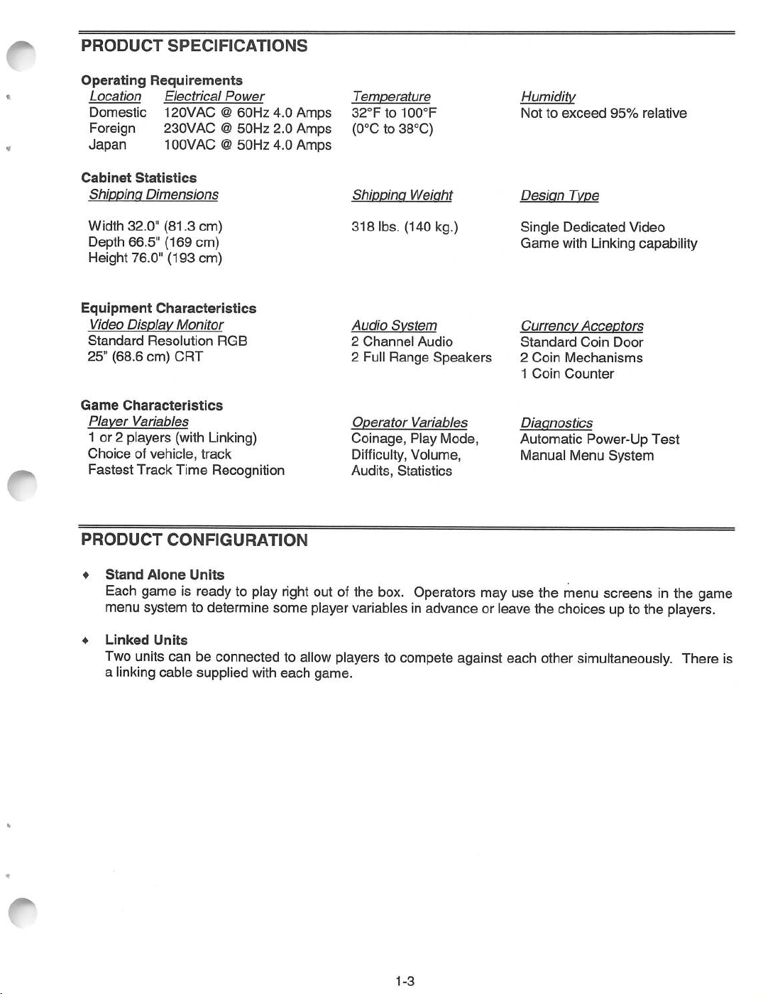
PRODUCT
Operating
Location
Domestic
Foreign 230VAC @
Japan
SPECIFICATIONS
Requirements
Electrical
Power
120VAC @
100VAC @
60Hz
50Hz
50Hz
4.0
2.0
4.0
Amps
Amps
Amps
Temperature
32°Fto
100°F
(0°C to 38°C)
Humidity
Nottoexceed
95%
relative
Cabinet
Shippinq
Width 32.0"
Depth 66.5"
Height 76.0"
Equipment
Video
Standard
25" (68.6
Game
Player
Statistics
Dimensions
(81.3
(169
(193
Characteristics
Display
Characteristics
Variables
Monitor
Resolution
cm)
CRT
cm)
cm)
cm)
RGB
1 or 2 players (with Linking)
Choiceofvehicle,
Fastest
Track Time Recognition
PRODUCT
♦
Stand
Alone
Each game is ready to play
track
CONFIGURATION
Units
right
out of the
menu system to determine some player variables
Shippinq
318
Audio
2
Channel
2 Full
Operator
Coinage,
lbs.
System
Range
Weiqht
(140
kg.)
Audio
Speakers
Variables
Play Mode,
Difficulty, Volume,
Audits,
Statistics
box.
Operators may use the menu screensinthe game
in
advance or leave the choices up to the players.
Desiqn
Single
Game
Currency
Standard
2
1
Diagnostics
Automatic
Type
Dedicated
with Linking capability
Acceptors
Coin
Coin
Mechanisms
Coin
Counter
Power-Up
Manual Menu
Video
Door
Test
System
♦
Linked
Two
Units
units can be connected to
a linking cable supplied with
each
allow
players to compete against each other simultaneously,
game.
1-3
There
is
Page 7

INSTALLATION
1.
Remove
signsofdamage.
all
items
AND
from
INSPECTION
shipping
containers and set
aside.
Inspect
the
exterior
of the cabinet
for
any
2. Remove the keys
There
are
electrical cords
3. Install
one
nut onto
from
the steering mechanism.
and
spare
parts in the
each
leg leveler. Tilt the cabinetasneeded
cash
Unlock
box.
and open the coin and cash box doors.
to locate four
threaded
holes
under
the cabinet. Install a leveler and nut into each hole. Do not tighten nuts at this time.
A
The
4. Stand cabinet upright and make certain it isina stable position.
level
location and
equally on
each
the cabinet. This game is intended for use onlyin a
corner
and
tighten
the
leveler nuts.
WARNING
cabinetistop
heavy.
Move
the game to its intended
fixed
position. Distribute weight
5. Remove the rear door of cabinet. Inspect cabinet interior for any signs of damage. Check all major
assemblies to
assure
that they
are
mounted securely. Ensure that nothing blocks fan
airflow.
6. An extra padlock may be installed to secure the rear door. A hasp is located in the spare parts bag.
Remove the two lock bracket nuts from inside the cabinet, above the rear door opening. Slide the
hasp
onto
the
boltssothatitprotrudes
7.
Modify
the lock plate at the top of the rear door. Remove the bolts and nuts from the lock plate, then
rotate the plate so that the slot
will
from the hole in
backofthe
cabinet,
then
reinstall
the
be above the door. Reinstall the bolts and nuts and tighten
nuts.
firmly.
CABINET
HASP
BRACKET
KEY
LOCK
BRACKET
SHOWN
FOR
HASP
REFERENCE
BRACKET
AND
LOCK
PLATE
1-4
ASSEMBLY
CARRIAGE
BOLT
LOCK
PLATE
CARRIAGE
BOLT
INSTALLATION
Page 8

The
power
at
the
rearofthe
firmly to
indentation
seat
cord
the
should
is with
cabinet.
line
point
the
spare
Match
cord.
Hold
downsothat
parts.
the
holesonthe
the
cord
the
Remove
flat
cord
exits
and
save
IEC plug with
against
the
toward
four
screws
the
cabinet
the
bottomofthe
from
the
prongsinthe
and
reinstall
cabinet).
line
cord
receptacle
the
cover
cover
and
plate
plate
push
(the
(PART
FOR
OF
CABINET
REFERENCE
SHOWN
ONLY)
LINE
SLINE
CORD
CORD
INSTALLATION
AND
PLUG
9. Refer to the game's Cabinet Wiring Diagram (Section Three of this manual) and check to
cable connectors
CONNECTORS
10. Plug the game
are
correctly secured. Inspect for
and
avoid making reversed connections.
into
a grounded (3-terminal)
AC
damaged
wall
outlet. Switch ON the game using the ON/OFF
connectors. Be
sure
see
NOT TO FORCE
switch located on the upper left top of the cabinet (when viewed from the player's position). The game
will
power up and begin self-diagnostics.Ifno errors are found, the
"attract"
modeofoperation.
game
will
automatically
enter
MAINTENANCE
♦
Viewing
Glass
Use the T27 wrench to remove the ten tamper-resistant screws on the control panel cover.
control panel
upward
glass retaining strip in place. Slide the glass upward slightly and swing it outward
the cabinet. Move the
♦
Cabinet
Use plastic-safe non-abrasive cleaners to
then use this to
♦
Controls
Use plastic-safe non-abrasive cleaners to avoid damaging the parts.
to expose the retaining
glass
downward
wipe
the decals or cabinet. Do not
strip.
until
it is free from the marquee.
avoid
Remove the three screws
damage.
apply
Apply
cleaner
cleaner to a clean
holding
cloth
until
the
it is free
or sponge,
directlyonartworkorcabinet!
Apply
cleaner to a clean cloth or
sponge, then use it to wipe the controls clean. Do not apply cleaner directly to the controls or cabinet!
that all
its
Pull
the
viewing
from
1-5
Page 9

SERVICE
Only
qualified
service personnel
should
perform
maintenance and
repairs.
The product guidelines
to all game operators and service personnel. Specific notes, cautions, and warnings
throughout this manual where they
apply.
Read the
SAFETY
pages thoroughly before beginning service.
will
apply
be found
This game
Observe
1.
Ensure
2. Discharge any static electricity build up in your
chassis.
3. Store the electronic
transport
4. DO NOT
will
5.
Always
♦
Marquee
Remove the ten tamper-resistant
uses
complex electronic components that are very
and follow
that
Do
the
the
this
these
A.C.
hard
removeorconnect
damage
the
replace
electronic
ground
precautions prior to handling
powertothe
BEFORE
assemblies
disk
drive,
wires,
touchingorhandling
assemblies
game
in an anti-static area. Use anti-static
the
CPU Board
any
electronic
and
shields,
screws
covers,
holding the
the
game
is turned OFF prior to
body
by touching
the
electronic
Assembly,
assemblies
void
the
etc., after
speaker
and
when
warranty.
completing
grille to the marquee. Remove five hex-
SENSITIVE
to static electricity.
electronics:
servicing
the
the
metal power
assemblies.
bagstostore
all
other
electronics.
the
cabinet power is ON.
maintenanceorservice.
electronics.
supply
head wood screws holding the marquee-retaining strip to the cabinet top. Hold the glass in place to
avoid breakage. Remove the retaining strip and set it aside.
grooves
The
Fluorescent
and
marquee
set
in a
safe
place. Do not over tighten
glass
could
fall
LamporStarter
outofthe
A,
^WARNING
cabinet
and
screws
break
Lift
the marquee glass out of the top
during re-installation.
when
the
retaining
stripisremoved.
Remove the marquee retaining strip, glass and artwork. Remove the fluorescent lamp locks. Grasp
the tube, give it a quarter turn
removal or installation. Carefully place a new tube into the
the
reinstall. Clean
tube to remove fingerprints and dust.
and
pull it from its socket.
The
starter also requires a quarter turn for
socket
and
rotate it a quarter turn to
or
This
If a
fluorescent
♦
Fluorescent
Remove
from the fluorescent light
the
cabinet. Slide
♦
Control
Use
the
tamper-resistant
expose
the
the
control
tube
Light
the
speaker
Panel
T25
wrenchtoremove
steering
panel,
drops
Assembly
grille,
the
assembly
screws
mechanism
ensure
and
breaks,
marquee
assembly.
slightly forward to
at
either
assembly,
that
harnesses
A,
WARNING
it will
implode
retaining strip, glass,
Loosen but do not remove
disengage
the
four
tamper-resistant
sideofthe
and
handlebar
control
ground
1-6
buttons,
strap
and
shatter
and
artwork. Disconnect
the
the
screwsatthe
protector.
and
wiring
are
reconnected.
glass!
screws
keyholes.
Pull
harnesses.
Use
fastening
Lift
control
the
control
careinhandling.
the
power cable
the
assembly
out
the
assembly.
panel
sides
panel
upward
Before
reinstalling
and
to
six
to
Page 10

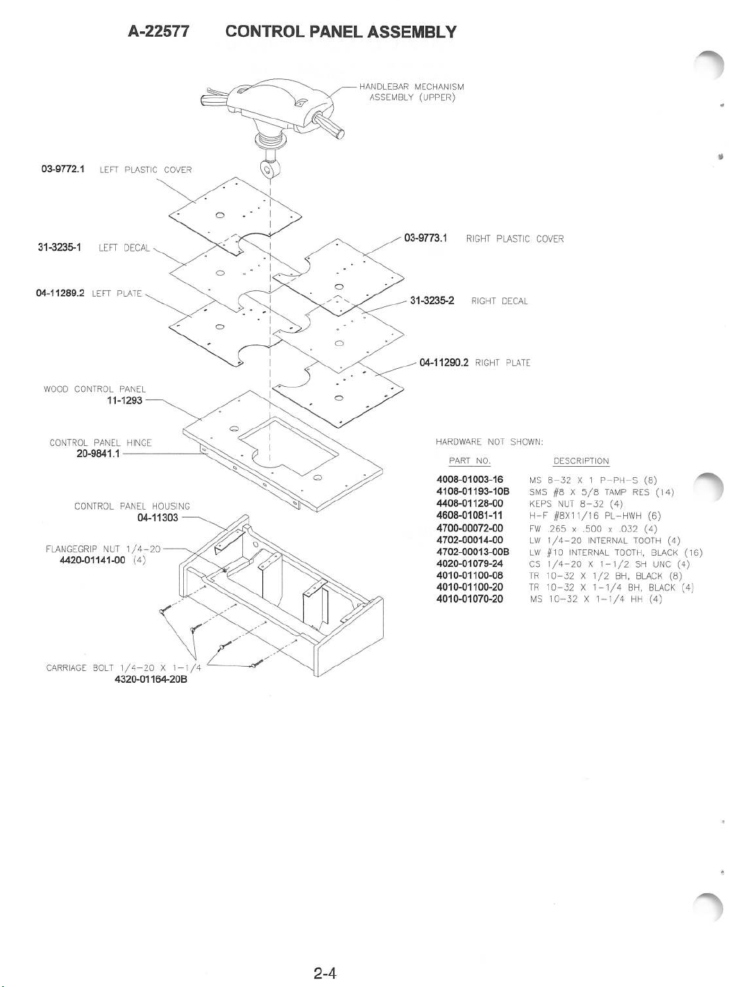
A-22577
CONTROL
PANEL
ASSEMBLY
WOOD
LEFT
CONTROL
PLASTIC
LEFT
LEFT
COVER
DECAL
PLATE
PANEL
HANDLEBAR
ASSEMBLY
MECHANISM
(UPPER)
RIGHT
RIGHT
RIGHT
PLASTIC
DECAL
PLATE
COVER
CONTROL
FLANGEGR1P
PANEL
CONTROL
CARRIAGE
HINGE
NUT
BOLT
PANEL
1/4-20
1/4-20
HOUSING
(4
1-7
NOTE:
LOWER
NOT
HANDLEBAR
SHOWN
MECHANISM
Page 11

♦
Handlebar
Use the T25 wrenchto remove
Mechanism
all
of the tamper-resistant
control
panel mounting screws except the
six screws at the center holding the metal control panel plates to the mounting brackets. Pull the
control panel upward
enoughtoexpose
and
the control wires. Label
and
disconnect
the
wires.
Support the mechanism and remove the remaining six mounting screws to free the mechanism from
the control panel plates.
mechanism
for repair.
from
the
While the steering mechanism is exposed, inspect the gears, switches,
hardware if the existing parts
Hold
control
the mechanism and slide the plates to the side while
panel.
show
Place
signs
the
mechanism
of wear.
on a
Remember
workbenchorother
and
cables. Install a new
to calibrate after installation.
lifting
suitable
the
surface
1ICR0SWITCH
HANDLEBAR
LEVERS
SHAFT
MOUNTING
HANDLEBAR
NUT
MECHANISM
-
ORIENTATION
CONTROL
SHOWN
PANEL
FOR
REFERENCE
1-8
Page 12

HAND
HAND
BRAKE
HAND
BRAKE
BRAKE
BRAKE
CABLE
HAND
END
PROTECTOR
NYLON
BRAKE
RETAINER
STOPPER
CABLE
UPPER
HANDLEBAR
ACCELERATOR
COVER
CABLE
HAND
GRIP
HANDLEBAR
MECHANISM
UPPER
LOWER
-
UPPER
LOWER
HANDLEBAR
HANDLEBAR
ACCELERATOR
HANDLE
HAND
HANDLEBAR
PROTECTOR
PROTECTOR
ASSEMBLY
GRIP
COVER
1-9
Page 13

>
z
D
r
m
>
m
m
o
</>
o
m
3D
BRAKE
RECOVERY
MICROSWITCH
SPRING
SPRING
MICROSWITCH
POTENTIOMETER
ARM
SPRING
GEAR
POTENTIOMETER
CENTRAL
SHAFT
^®>
V^jP
STOPPER
END
GEAR
STOPPER
ROCKER
BEARING
ARM
—
RECOVERY
MICROSWITCH
SPRING,
LEVER
THROTTLE
Page 14

♦
Brake
Cable
Remove
off the steering mechanism
the
three
T-20
tamper-resistant
and
screws
set
it aside. Open the control panel.
from
the
handlebar
mechanism
Separate
cover.
the
lower
Lift
end
cable from the microswitch lever. Remove the microswitch lever retaining clip and pull the lever from
post.
Rotate
the
handlebypressing
the
handlebythe
♦
its
at
from
Accelerator
Remove the three T-20 tamper-resistant screws from the steering mechanism cover.
the steering mechanism and
from the microswitch lever. Remove the microswitch lever retaining clipand
post.
Rotate
of the accelerator cable retainer. Remove the barrel end of the cable
♦
Handlebar
Open
the
only.
Remove the nut at the handlebar shaft and the alien bolt holdingthe shaft to the handlebar.
Remove the handlebar off its shaft and
and
protectors
♦
Accelerator
the
levertoremove
the
sheath.
Cable
the
levertoremove
Covers
control panel cover.
Grip
are
and
Protectors
now
freetoremove.
the
barrel
endofthe
undersideofthe
set
it aside. Open the control panel.
the
barrel
Disconnect
lift
cable
retainer until
endofthe
the
accelerator
cable.
itout of the control panel. The lower handlebar housing
cable.
Useanalien
and
Disconnect
the
cableisloose.
Separate
from
brake
cablesatthe
the
ball
endofthe
Pull
the
Lift
the cover off
the lower end of the cable
pull
the lever from its
wrenchtoloosen
the accelerator grip.
microswitch
Remove the upper handlebar cover. Remove the accelerator grip by carefully prying it from the
accelerator handle and
holding
accelerator
the accelerator to the handlebar to expose the cable stop. Disconnect the cable
handle
and
pulling
pull
the
it away. Disconnect the accelerator cable by loosening the screw
from
handletoremove
it from
the
handlebar.
the
cable
the
the
cover
of the
cable
cover
levers
♦
Brake
Handle
Remove the upper handlebar cover. Remove the handlebar
handlebar
underside ofthe cable retainer
Remove the handle
from
the
♦
Accelerator/Brake
Open
the
remove the
♦
View/Start
Use the T25 wrench to remove the ten tamper-resistant
the
panel
and
Grip
grip
by carefully
while
pullingitaway.
from
handlebar.
Switches
Disconnect the
until
the cable is loose.
ball
end of the cable at the handle bypressing the
Pull
the cable
the handlebar by loosening the alien
bolt
control panel cover. Disconnect and label the switch wires.
switch
Buttons
mounting
and
Switches
screws. Replace switches only
with
ones of the same ratings.
mounting
upward
enough
to expose the
switches.
Label
and
disconnect
from
on the
Use
screws
pryingitfrom
the
the handle by the sheath.
clip
and sliding the handle
a flat-blade screwdriver to
from
the control panel.
wires.
Gently
bend the
prong of the holder just enough to slide the switch off the pushbutton holder. Unscrew the nut from
the pushbutton housing and remove it from the control panel cover.
♦
Coin
Meter
Switch
meter is located on a plate at the
off
power to the game.
Unlock
vault
the cash door and
bottom.
Remove
swing
it open. Remove the cash tubs. The
the screws and
lift
the plate just enough to
disconnect the meter wires from the harness. Record the meter count before testing or replacement.
♦
Coin
Mechanism
Switch
coin
seats
Turn
operation.
off
power to the game.
mechanism separately to clean or replace
fully
in the holder upon reinstallation. Close and lock the release latch, then close the door.
on the game and changethe
Unlock
mechanism
the coin door and swing it open.
withadifferent
setup, then test
type.
known
Unlatch
and remove each
Ensure that the mechanism
good
and bad
coinstoverify
Pull
large
1-11
Page 15

Bill
Validator
The
game's
wiring
harnessasmanufactured does not support a
although the coin door
to install a bill
validator,
separate
will
accept such a mechanism.Itmay be possible to
but
this
has
not
been
tested.
bill
validator connection,
rework
the
wiring
harness
Monitor
Remove the
groove.
Monitor
THE VIDEO MONITOR IS HEAVY, WITH
ASSEMBLY.BE
The monitor
However,
MUST
♦
Speakers
NOTE:
sure
Two 5.25"
Remove
disconnect
speakers
Bezel
Remove
ISOLATE
The
that
any
the
dashboard
Read
does
when
speakers
replacement
full
range
speaker
the
cabling
and viewing glass. Grasp the monitor bezel at
the
bezel
from
these precautions thoroughlybefore beginning this procedure.
SURE
operating
THE
IT IS FIRML Y
not
require isolation from the A.C. line
outside
MONITOR
are magnetically
speakers
speakers
grille.
and
remove
from the enclosure. Carefully
the
cabinet.
A
!>
CAUTION
MOST
SUPPORTED
the
cabinetorservicing
FROM
LINE
VOLTAGE
shieldedtoprevent
are
also
magnetically
are
under the marquee. Remove
The
speakers
the
come
nuts on the mounting
reseat
the
enclosure. Refer to the Cabinet Wiring Diagram for correct
OF THE WEIGHT
AS
IT IS
REMOVED
the
WITH
AN
video
shielded.
out from
the
outsideofthe
screws
seals
upon completing any task in the
speaker
the
bottom
TOWARD
FROM
voltage
monitor
ISOLATION
monitor
the
marquee, glass,
and
THE
THE
in normal operation.
on a
TRANSFORMER.
color impurity. Be
cabinet. Be
before attempting to
polarity.
lift
FRONT
CABINET.
test
it out of the
OF
bench,
and
artwork.
sure
remove
speaker
THE
YOU
to
the
1-12
Page 16
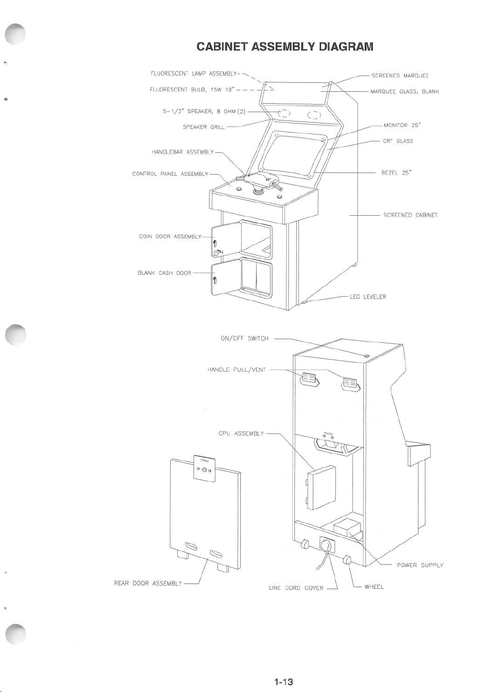
CABINET
ASSEMBLY
DIAGRAM
FLUORESCENT
FLUORESCENT BULB, 15W
5-1/2"
HANDLEBAR
CONTROL
PANEL
COIN
DOOR
ASSEMBLY
BLANK
CASH
DOOR
LAMP
ASSEMBLY
SPEAKER,8OHM
SPEAKER
GRILL
ASSEMBLY
ASSEMBLY
18"
ON/OFF
(2)
SWITCH
LEG
SCREENED
MARQUEE
LEVELER
MONITOR
CRT
GLASS
BEZEL
SCREENED
MARQUEE
GLASS,
25"
BLANK
25"
CABINET
REAR
DOOR
ASSEMBLY
HANDLE
CPU
PULL/VENT
ASSEMBLY
LINE
CORD
COVER
POWER
SUPPLY
1-13
Page 17
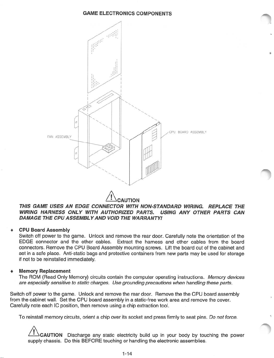
FAN
ASSEMBLY
GAME
ELECTRONICS
COMPONENTS
CPU
BOARD
ASSEMBLY
THIS
GAME
WIRING
DAMAGE
♦
CPU
Board
Switch off power to the
EDGE
connectors.
set
in a
USES
HARNESS
THE
CPU
Assembly
connector
Remove
safe
place. Anti-static
AN
ONLY
ASSEMBLY
game.
and
the
the
if not tobereinstalled immediately.
♦
Memory
The
are
Switch off
from
the
Carefully note
To reinstall
Replacement
ROM
(Read
especially
powertothe
cabinet
each
memory
A.
^CAUTION
supply
chassis.
Only Memory) circuits contain the computer operating instructions. Memory
sensitivetostatic
game.
wall.
Set
the
IC position,
circuits,
Discharge
Do this
EDGE
WITH
Unlock
other
CPU
Board
bags
Unlock
CPU
board
then
orientachip
BEFORE
A<
CONNECTOR
AUTHORIZED
AND
VOID
and
cables.
Assembly
and
protective containers from new
charges.
and
remove
any
Use
remove
assembly
using a chip extraction tool.
over
static
touching
^CAUTION
WITH
THE
NON-STANDARD
PARTS.
WARRANTY!
USING
WIRING.
ANY
OTHER
REPLACE
PARTS
remove the rear door. Carefully note the orientation of
Extract
the
mounting
harness
screws.
and
Lift
the
other
board
parts
cables
from
outofthe
maybeused
the
cabinet
for
storage
devices
grounding
the
in a static-free work
its
socket
electricity build up in
or handling
rear
precautions
door.
Remove
and
press
the
electronic
when
handling
the the
area
and
firmly to
your
seat
bodybytouching
assemblies.
CPU
remove
pins. Do
these
board
the
parts.
assembly
cover.
not
force.
the
power
THE
CAN
the
board
and
1-14
Page 18

♦
Power
Supply
Switch off power to
IEC A.C.
connector
front and two rear
the
from
screws
game.
the
Remove
rearofthe
screws,
supply
from the supply, then
then unlock
and
the
D.C.
lift
it off of the power
and
remove
connector
chassis.
the
rear
door. Unplug
from
the
front.
Note voltage setting.
Remove
the
two
To reinstall the power supply,
♦
chassis
Fan
and
align
the
mounting holes. Install the four
set
the voltage switch to the correct value.
screws
and
Set
the supply on
the two power connectors.
the
Switch off power to the game. Remove the cabinet rear door. Open the electronics assembly cover.
Disconnect
the
wiring
harnesses,
linking cable,
and
fan power
connector
from
the
circuit board.
Remove
the circuit boards from the electronics assembly box. Remove the four nuts holding the fan to the
electronics
assembly
box.
power
1-15
Page 19

LINKING
INTERCONNECTING
1.
Verify
the operation of the existing games before making any changes. Unlockthe coin doors of both
cabinets and press the TEST
screen
different
at the bottom. Both cabinets must have the
versions
GAMES
may
cause
MODE
games
switches. Check the
same
to halt or
reset
at random.
VERSION
information displayed on the first
version number. Linking
games
2. Turn OFF the power for both cabinets. Unlock and remove the cabinet rear doors. Find the
cable.
3. The
side
Mate the
4.
Route
cable
5. Turn ON
serious
reportedonthe
6.
Press
the
for
Use
DIFFICULTY
It is
linking
LINKS
connectors
the
cable
through
the
errors
shipped
cable connectors are keyed to
CONNECTOR
power for both cabinets.
with
the
and
press
through
the
are
screen,
the
slotornotchinthe
detected,
refer to Troubleshooting in
spare
socket
firmly to
cabinet
the
games
parts.
(nearest
seat
interior
second
The
will
fit
one way. Orient the
the
POWER
fully.
Do not
and
outofthe
cabinet
games
enter
will
the
Section
the TEST MODE switches to enter the menu systems.
menu
one
the
cabinet,
brake
screenstothe
and
handle
setting.
GAME
SLAVE for
to go to
Do
not
ASSIGNMENTS
the
other. Each machine
the
DIFFICULTY setting. Both
turn off the
power
screen.
or your
connector)onthe
use
excessive
slotornotch.
and
attach
it to
startupand
"attract"
mode
Four
Select
must
machines
changes
for
Press
LINK
have a distinct
willbelost.
linking
cable end plug over the right
Electronics
Assembly.
force.
Route
the
free
the
electronicsasabove.
begin
the
Power On tests. Ifno
automatically If
there
assistance.
the
VIEW button to scroll through
TYPE,
must
then
LINK
have
choose
the
TYPE setting.
endofthe
are
same
with
linking
"
errors
MASTER
7.
Press
VIEW to scroll through
EXIT
AND
SAVE
8. Both
9.
10. If
machines
detected,
Retract
the
cables
Reinstall
the
top
the
cabinets
the
any
excess
away
the
and
sidesofthe
games
rear
need
LINKTYPE setting to NO
disconnect
the
cable.
CHANGES.
will
reset.
will
cable
from
doors
to be
o
the
menu
The
games
enter
the
"attract"
back
into
the
the
casters
onto
the
cabinets.
rear
doors
and
separated
LINK
for both
Do not turn off the
gaelcam
o
LOCATION
r (
PCB(ONNfCIOR
O C
OF
screenstothe
will
startupand
mode
automatically
cabinetssothat
during relocation
Lock
the
tighten snugly.
for
service
game
power
CONNECTOR
or relocation,
cabinets. Make
prior to saving the
)
o
5
EXIT MENU
begin
the
the
cablesdonot
and
protectsitsomewhat
rear
doors
Close
j-M-dilfcil
STEERS
LINKS
CONNSCIOK
FOR
LINKING
and
use
PowerOntests.
and
synchronize
and
remove
and
lock
the
enter
the
menu
suretosave
changes
pN
ij
O
CABLE
the
brake
handletoselect
If no
errors
quickly.
touch
the
floor.
from player's feet.
the
key. Install
cash
box
and
systems
these
changes
or they willbelost.
o
POWER
are
This
keeps
screws
coin doors.
and
return
before
at
the
you
">
1-16
Page 20
GAME
OPERATION
STARTING
Each time the
These
displays information about the software version and condition of the hardware.
tests
*
* Press and hold the coin door TEST button to activate the TEST
Once all Power-up tests have been passed, the game
self-diagnostic
fails, then an error
If
no buttons are pressed, the system
fromatypical
Insert currency to start the game. Play begins after a
UP
game
is first turned on or power is restored, it begins executing code out of the boot
tests
automatically verify and report the condition of
message
game are alternated
will
be displayed for
will
quickly
with
previous
the
hardware.
If
any of the
each
test.
complete all tests then load and run the game.
MODE
goes
into its "attract mode."
high
scoresinan endless pattern
circuit
is chosen. The game
menu system.
until
will
Scenes
game playstarts.
progress
ROM.
The
screen
individual
and sounds
until
is exhausted. The game automatically returns to the "attract mode" when play ends.
GAME
The
avoiding obstacles and other vehicles. Players can choose from several biker personalities and circuits.
Each
is to complete
speed,
Players compete against drone
of a circuit automatically advance to the next stage.
RULES
game
involves a pizza delivery biker who rides through the city in competition with another driver while
circuit
has four stages: three pizza deliveries and the return to the pizzeria. The object of the game
all
and
of the deliveries and
point
bonuses
throughout the course.
delivery
return
to the pizzeriainthe shortest time possible. There are
bikers
or other
players.
Players
who
finish
one of the
four
stages
time
time,
INDIVIDUAL
Insert
currency or tokens to start the game. Press the
move
the
particular
CHOOSEABIKER,
play.
competition
The
players must pass several
The more bonuses collected
MULTIPLE
Two
playersonlinked
selection of a circuit and a
their respective pizzerias and
player is scoring more points during competition.
STATISTICS
An
on-screen display continually updates status
Scoreisthe
Best lap is the fastest
initials
Lap
XJeft
Rev
Speedometer
Icon showsthe player's current
linked cabinet ("1UP/2UP").
PLAY
handlebars
difficulty
PLAYERS
appear
time
is the elapsed time for the current player.
indicates the time remaining to complete the circuit.
counteristhe
to
the
desired
level:
EASY
select a character
begins
automaticallyasbikers
CHECKPOINTS
during
cabinets can
biker.
competition
player's
present
timeinwhich
nexttothe
shows the current scooter speed.
timeinminutes
RPMofthe
circuit
and
(Margherita),
MEDIUM
with
the handlebars and press the
and
the
run,
the faster the playerfinishes the stage.
compete
head-to-head.
When both players have completed their selections, the bikers leave
begins.
overall
score.
any
scooter's
position
player
and
motor.
and indicates whether the competitor is a drone
START
select
button.Atthe
it with
the
START
(Capricciosa),orHARD
roll
out of the
collect
An
indicator
information
pizzeria
onto
bonuses to successfully complete the pizza
The game
beginsasin
bar at the top of the screen shows
for the
player:
has ever completed the present
seconds.
CHOOSEARIDE
button.
Each
circuit
(Diabola).Atthe message
START
the
buttontobegin
circuit.
During
individual
circuit.
play
That player's
("CPU")
message,
has
game
the
race,
run.
with
the
which
or a
a
1-17
Page 21

PLAYER
♦
START
This button
This same button selects items
♦
HANDLEBARS
CONTROLS
Button
allows
players to begin or continue
from
the TEST
play.Italso selects each player's
MODE
menus during service or adjustment.
circuit
The handlebars are used to guide the biker's scooter on the streets and to avoid fixed or moving
objects.
wheeltojumpinthe
menus
♦
BRAKE
Pushing
during
down on
service.
air.
the
The
handlebars
handlebars
while
move
the
the
scooter
cursor
is in motion
to different
causes
the
scooter's
selectionsinthe
TEST
The scooter brakes are activated by squeezing the handle opposite the accelerator grip. When the
handle is
♦
ACCELERATOR
released,
the
scooter
beginstoroll.
The right-hand handlebar grip is also the scooter's accelerator. The handlebar grip rotates downward
to
accelerate
♦
VIEW
BUTTON
the
scooter.
This button controls the player's road perspective during play. Players can select from one of several
views.
and
front
MODE
biker.
VIEW
BUTTON
START
TYPICAL
BUTTON
PLAYER
CONTROL
LOCATIONS
HANDLEBAR
ASSEMBLY
MECHANISi
ELERATOR
GRIP
1-18
Page 22

OPERATOR
CONTROLS
CABINET
♦
♦
♦
CONTROL
♦
♦
♦
SWITCHES
Power
The
Monitor
The
Slam
Volume
The
Press
The
Test
The
run
Service
Switch
Power
Monitor
Tilt
Volume
(usually on
Switch
Remote
Remote
Switch
SWITCHES
Down
and
Down
the
turns
off
Adjustments
Adjustment
toporback
the
game
(typically in
panelofthe
during service. It
Board
(on coin door) prevents cabinet
Volume
and
Up
Volume
Buttons
(frequently mounted on or behind coin door in many
Up push-button switches increase or
either button brieflyto make minor changes.
Attract Mode volume is controlled independently of
Mode
Button
Test
Mode push-button switch enters the menu system.
automatic
Credit
(mounted on or behind the coin door on
tests.
To
save
Buttons
changes,
(mounted on or behind the coin door on
use
The Service Credit push-button switch allots credits
cabinet)
does
not
reset
the
the
cabinet
sets
the video display for optimum viewing.
abuses
near
the
monitor or control panel)
suchaspounding to obtain free
decrease
Press
and hold a button to make major changes.
NOTE
the
Game
Mode volume.
the
EXIT
selectiononthe
without
games
changing the game's bookkeeping total.
equipped with this switch)
Press
the
TEST
games
equipped
game
variables.
game
sound
Test
Mode button briefly to
MODE main
with
this switch)
menu.
games.
games)
levels.
These buttons may also be used instead of the player controls when operating the menu system.
NOTE:
The coin door must be open to reach the controlswitches in most games.
TYPICAL
CONTROL
SWITCH
LOCATIONS
1-19
Page 23

TEST
MODE
MENU
SYSTEM
SYSTEM
Game variables and diagnostics
MODE
OVERVIEW
Main
Menu screen
allows
are
presented in a series of on-screen TEST MODE menus. The TEST
the operator to select one of several testing or statistical features and to
save changes made in the sub-menus. Each sub-menu screen displays one specific group of choices
a detail menu. The detail menu presents data, settings, or runs a test. You must be at the detail menu
level
to detect errors, make changes, or activate tests.
are
used
to move through the
ORGANIZATION
TEST MODE main menu
menus
screen
and
start or stop particular routines.
items fall into three categories: options, statistics,
be activated manually by pressing the START button after moving the cursor to them with the brake
handle.
Sub-menu screen items offer the operator choices
while others may have more than one. Sub-menus always have an option to return to the previous menu.
Detail-menu
make
screen
changes.
To scroll through the menus,
To return
press
SCREEN
the
the
indicated button. This
ADJUSTMENTS
items contain specific information.
There
is always a way to go back to
use
the
VIEW button. Only one highlighted item can be
game
to normal,
select
EXIT AND SAVE CHANGES from
saves
any
changes
The SCREEN ADJUSTMENTS display provides patterns for verifying the monitor performance or making
adjustments.
There
are
also
basic
testsofthe
critical CPU Board
Both
the operator controls and the player controls
within
a category. Some items have no sub-menu
The
operator
the
previous
madeinthe
must
menus
from
the
previous
components.
menus.
select
the
last
and
tests. Items
an item to run
detail menu
selected
TEST
MODE menu, then
tests
screen.
at a time.
must
or to
in
Pressing the TEST button
causes
the SCREEN ADJUSTMENTS display to
appearonscreen.
This
test
screen also displays during the start-up self-test, and includes patterns for adjusting monitor controls.
Convergence patterns
across
the
centerofthe
appearateach
screen.
The monitor controls to adjust
the
wall of
The
After making
next
cabinet,ormounted
software
menu
version,
any
screen.
check
changesoradjustmentstothe
Patterns
these
near
sum,
corner. Color bars for hue and brightness adjustments display
and
bars
should be
sharp
and
distinct.
features may be at the rear of the coin door cavity, attached to the
the
and
neckofthe
hardware
CRT.
RAM testing
video monitor,
status
press
also
are
the
VIEW button to
displayed on
advancetothe
the
screen.
SCREEN
ADJUSTMENTS
1-20
DISPLAY
AND
MENU
Page 24

INPUT
TEST
START:
VIEW
CHANGE:
BRAKE:
ACCELERATOR:
HANDLE:
HANDLE
COIN
SERVICE:
INPUT
The
button
leftto right
HANDLE
COIN CHUTE value to
If
TEST
INPUT
TEST screen has checks of the game controls and coin chute. Pressing each control panel
causes
an indicator on screen to change from OFF to ON.
causes
UP value to
the
change
HANDLE
from OFF to ON. Dropping a coin down
change
values to change. Pressing down on the steering mechanism
briefly from
the control indicatordoes not change as expected, check the
UP:
CHUTE:
Push
view
OFF
for
to ON.
next
page
OFF
OFF
OFF
OFF
000
OFF
OFF
OFF
127
Moving
wiring
the steering mechanism from
the
coin mechanism
harnesses for that device,
causes
causes
the
the
Refer
to Section Four, Troubleshooting.
The normal
r
value should be
mechanism using the
HANDLE
within
values are 000 at
full
left and 256 at
full
rightfor the left-hand number. The
same
the range of 108 to 148 when the handlebar is centered. Recalibratethe steering
HANDLE
ADJUST
test
if necessary.
If
each control works properly, press
VIEW
to go to the next testing menu.
1-21
Page 25

GAME
ASSIGNMENTS
1 COIN(S)
2 CREDIT(S)
2 CREDIT(S)
LINK
TYPE:
GAME
ADVERTISE
DIFFICULTY:
PASS
PROCESS
ASSIGNMENTS
NEXT
Push
Push
Push
SOUND:
LEVEL:
BAR:
view for next
brake
start
This screen contains settings for game parameters such as coin options,
The
attract volume.
displayed values
are
factory settings.
1 CREDIT(S)
START
CONTINUE
NO
YES
HARD
YES
NO
for
select
for
confirm
LINK
page
linking,
game
difficulty,
The left-hand column contains the type of settings, whereas the right-hand column contains the
the current setting.
button to
change
Squeeze
a setting when it is flashing.
COIN(S) is the number of coins required to obtain the number of CREDIT(S)
The CREDIT(S) lines in the left-hand column
a
game.
LINK
When
COIN(S) is
TYPE controls the
is connected. To connect two linked games, each must have an individual setting for
properly.
section
One
above
game
titled
mustbeset
LINKING.
the brake handle to move through the various settings.
set
the number of credits required to START or CONTINUE
set
to zero,
game's
the
linking
capabilities.
to MASTER,
game
allows free play.
and
Set
the
the
game
other
to SLAVE. For
to OFF ("NO
Press
the START
setinthe
opposite column.
LINK")ifno other cabinet
more
linking
information,
to work
and
status
see
of
the
ADVERTISE SOUND controls whether the
DIFFICULTY
from
"EASY"to"HARDEST."
PASS
four
stages
stage
of the circuit
PROCESS
Press
the
NEXT
changes
LEVEL
the level of expertise a player needs to advance to the next
sets
whether a player can advance to the next circuit after successfully finishing the
of each circuit. YES rewards the player
and
requires the player to add coins.
BAR is a software development tool. It should always be
VIEW
buttontoadvance
to
the
game
next
menu
will
have
sound
with
a new circuit. NO
screen.
1-22
during the time between
stage
ends
the
game
set
to "NO."
games.
through a range
after the fourth
Page 26

PUSH
Push
HANDLE
START
view for
ADJUST
TO
ADJUST
next
page
HANDLE
MOVE
AND
RIGHT
Push
HANDLE
HANDLE
ADJUST
ADJUST recalibrates the steering mechanism.
screen. When the screen displaychanges to showthe POTE and
fully
to the
left,
then
fully
mechanism
to the
ADJUST
POTE:
NORM:
===|==
HANDLE
TO
128
128
ADJUST
view for next
right.
The game
LEFT
page
Press
START at
NORM
will
measure the value of the potentiometer
the
HANDLEADJUST
scales, move the steering
menu
at each extreme and take the arithmetic mean of the values to determine a centering point.
The values shown on screen during this test are for reference purposes only. The center value of the
POTE
indicator
right-hand
should be between 100 and 150, and the left-hand
limit
shouldbeless
After completing this test,
push
than
235.
the
VIEW button to
The
value
of NORM is
advance
limit
the
meanofthe
to the next
should be 20 or greater,
two
limit
values.
menu
screen.
while
the
1-23
Page 27

LAMP
COIN
BASS:
SOUND
SOUND
SOUND
OUTPUT
START
COUNTER
CHANNEL
CHANNEL
CHANNEL
Push
TEST
view for next
6
1
2
3
page
OUTPUT
The
OUTPUT TEST
lever to
LAMP
COIN COUNTER
coin
TEST
select
START is not
counter
meter
screen
each
test,
used
tests
the coin mechanism switch contact. With
advancesbyone
and
in this
items
check
the
START button to activate or make
game.
BASS plays music continually to adjust
bass)tonine
The
SOUND
speaker,
cabinet).
Press
VIEWtoadvance
(full
bass).
CHANNEL
Channel 2 is
items
the
right-hand
to
sendatest
the
next
menu
the operation of output signals from the CPU. Use the brake
unit.
the
tone of the
tonetothe
speaker,
screen.
changesineach
each
pressofthe
sound
output.
selected
channel.
The
level is adjustable from zero (no
Channel1is
and Channel 3 is an optional sub-woofer (not
category.
START button, the
the
left-hand
used
in this
1-24
Page 28

BOOK-KEEPING
1/2
BOOK-KEEPING
2/2
COINS:
COIN
CREDITS:
BOOK
SERVICE
TOTAL
NUMBER
CONTINUE
P1
GAMES:
P2
GAMES:
KEEPING
CREDITS:
CREDITS:
OF
GAMES:
Push
The BOOK KEEPING
The first
screen
includes information on the number of coins accepted, credits allotted, service credits
GAMES:
view
screens
for
next
display general
page
1234
1234
1234
1234
1234
1234
1234
1234
game
TOTAL
PLAYTIME:
AVERAGE
LONGEST
SHORTEST
TIME:
Push
play statistics.
TIME:
TIME:
TIME:
view for
next
00000
000
page
0000
00 00
00
00 00
00
00
allotted, total credits allotted, games completed, continued games completed, single-player games, and
linked
games. The second screen displays information on the duration of a
There are no adjustable settings on either ofthe
totals, go to the
RESET
HALLOFFAME.
final
menu page and choose RESET
Press
VIEWtoadvancetothe
BOOK
KEEPING
BOOK-KEEPING.
next
screens. To reset the bookkeeping
menu
screen.
typical
game.
To delete the high scores, select
TIME
The
HISTOGRAM
TIME
HISTOGRAM
game. The top part of the
shows
the
Press
VIEWtoadvance
numberofplayers
screen
screen
to
the
TIME
HISTOGRAM
0-2:
2.5-3
3.5-4
4.5-5
5.5-6
7-8:
WINh
WINh
WINh
JERS
JERS
JERS
1234
1234
1234
1234
1234
1234
MEDIUM:
HOT:
LIGHT:
Push
view
for
2-2.5
3-3.5
4-4.5
5-5.5
6-7:
8-X:
nex
1234
1234
1234
1234
1234
1234
1234
1234
1234
tpage
contains information on the number of players to win the circuits of the
shows a range of total game play times. The bottom of the screen
winning
next
each
menu
circuit.
screen.
1-25
Page 29
GAME
STATISTICS
GAME
STATISTICS
MARGHERITA
GAMEOVER/
1:
123
2:
123
3:
123
4:
123
CAPRICCIOSA
GAM
EOVER/
1
123
2
123
3
123
4
123
Push
GAME
Push
CONTINUE/
123
123
123
123
view for
STATISTICS
CONTINUE/
/
123
/
123
/
123
/
123
view for
next
next
/
/
/
/
WINNERS
page
WINNERS
page
123
123
123
123
123
123
123
123
DIABOLA
GAMEOVER/
1:
123
2:
123
3:
123
4:
123
Push
CONTINUE/
/
123
/
123
/
123
/
123
view for next
/
/
/
/
page
WINNERS
123
123
123
123
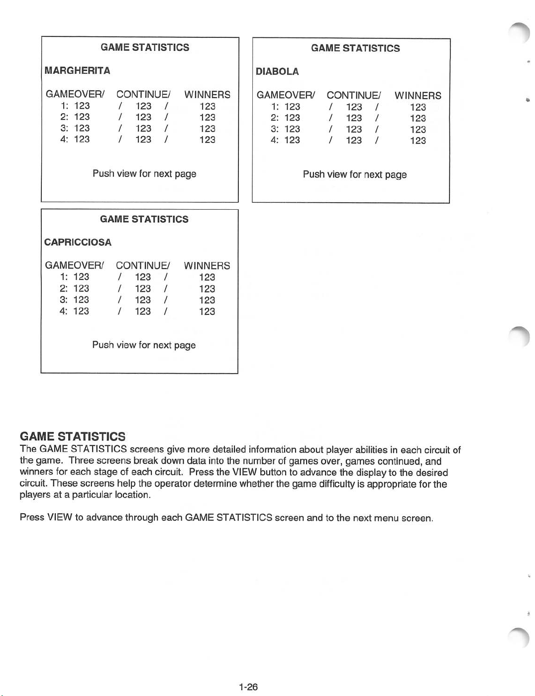
GAME
The
the game. Three
winners for each stage of each circuit. Press the
STATISTICS
GAME
STATISTICS
screens
screens
break down
give more detailed information about player abilities in
data
into the number of
VIEW
games
button to advance the display to the desired
circuit. These screens help the operator determine whether the game
playersata particular location.
Press
VIEW to
advance
through
each
GAME STATISTICS
1-26
screen
andtothe
over,
games
difficulty
each
circuit of
continued, and
is appropriate for the
next
menu
screen.
Page 30

EXIT
EXIT
MENU
EXIT
RESET
RESET
Push
Push
Push
WITHOUT
AND
HALL
BOOK-KEEPING
view for
brake
start
SAVE
for
for
SAVE
CHANGES
OF
FAME
next
select
confirm
CHANGES
page
This menu gives options for saving or discarding changes made in previous menus and resetting high
scores
will
and
discard
book keeping totals. Turning off
any
changestoprevious
screens.
the
machine before choosing EXIT AND SAVE CHANGES
To keep all
changes
made in previous screens,
use
the brake lever to highlight
CHANGES, then press START to save the changes and return the game to
EXIT
ATTRACT
AND
mode.
SAVE
1-27
Page 31

TM
RADIKAL
BIKERS
SECTION
TWO
PARTS
Warning
USE
OF
NON-ATARI
DAMAGE!
* For safety
* Substitute parts or modifications may void FCC type acceptance.
USE
and
PARTS
ONLY
ATARI
reliability, substitute parts
OR
CIRCUIT MODIFICATIONS MAY
AUTHORIZED
PARTS.
and
modifications are not recommended.
CAUSE
SERIOUS
INJURY
OR
EQUIPMENT
Page 32

RADIKAL
BIKERS (30038)
CONTROL
A-22577
FLUORESCENT
20-10480
FLUORESCENT
A-22365
FLUORESCENT
24-8809
5-1/2"
HANDLEBAR
(SEE
DETAIL
PANEL
ASSEMBLY
STARTER, 1
LAMP
ASSEMBLY
BULB,
15W
SPEAKER, 8
5555-15098-00 {2\
SPEAKER
01-11859
GRILL
ASSEMBLY
DRAWING)
5W-
1
VIDEO
OHM
CABINET
FRONT
VIEW
25"
POP
HEADER
31-3238
SCREENED
31-3236-1
MARQUEE
08-7456-4
MONITOR
5675-15215-01
CRT
08-7456-10
BEZEL
03-8497
GLASS,
GLASS
25"
MARQUEE
25"
1
LANK
COIN
DOOR
(SEE
DETAIL
&
APPLICATION
DECALS:
PART
31-3232
31-3233
31-3234-1
31-3234-2
31-3234-3
31-3235-1
31-3235-2
31-3237
ASSEMBLY
NO.
DRAWING
CHART)
CABINET
CABINET
CONTROL
CONTROL
CONTROL
CONTROL
CONTROL
BEZEL
DESCRIPTION
SIDE
SIDE
PANEL
PANEL
PANEL
PANEL
PANEL
BOTTOM
PANEL,
PANEL,
LEFT
RIGHT
HOUSING,
HOUSING, RIGHT SIDE
HOUSING,
OVERLAY,
OVERLAY, RIGHT
LEFT
FRONT
LEFT
SIDE
LEG
LEVELER
08-7377
SCREENED
04-11305
(4)
CABINET
2-2
Page 33

RADIKAL BIKERS
(30038)
RELATED
(SEE
MAIN
DOOR
DETAIL
HARNESS
ON/OFF
5642-14632-00
HANDLE
03-8326
LOCK
DRAWING)
H-22578
ASSEMBLY
20-10487
CPU
(SEE
DETAIL
VIDEO
SWITCH
PULL/VENT
(2)
HARDWARE
ASSEMBLY
DRAWING
CABINET
REAR
-
25"
VIEW
REAR
(SEE
DOOR
DETAIL
ASSEMBLY
DRAWING)
20-10435
LINKING
(SEE
CABLE
LINE
CORD
APPLICATION
CHART'
LINE
CORD
01-10714
COVER
FIXED
20-9945
POWER
20-10167
CASTER
SUPPLY
WHEEL
(2)
2-3
Page 34
A-22577
CONTROL
PANEL
ASSEMBLY
03-9772.1
31-3235-1
04-11289.2
WOOD
CONTROL
FLANGEGRIP
4420-01141-00
LEFT PLASTIC COVER
LEFT DECAL
LEFT PLATE
CONTROL
20-9841.1
CONTROL
PANEL
NUT
PANEL
11-1293
HINGE
PANEL
1/4-20
04-11303
(4)
HOUSING
HANDLEBAR
ASSEMBLY
MECHANISM
(UPPER)
03-9773.1
31-3235-2
04-11290.2
RIGHT PLASTIC COVER
RIGHT DECAL
RIGHT PLATE
HARDWARE
4008-
4108-
4408-
4608-
4700-
4702-
4702-
4020-
4010-
4010-
4010-
PART
01003-16
01193-1
01128-00
01081-11
00072-00
00014-00
00013-00B
01079-24
01100-08
01100-20
01070-20
NOT
NO.
OB
SHOWN:
MS
8-32
SMS #8 X
KEPS
H-F
FW
.265x.500x.032
LW
1/4-20
LW
#10
CS
1/4-20X1-1/2
10-32X1/2
TR
TR
10-32X1-1/4
MS
10-32X1-1/4
DESCRIPTION
X 1
5/8
NUT
8-32
#8X11/16
INTERNAL
INTERNAL
P-PH-S
TAMP
RES
(4)
PL-HWH (6)
TOOTH
TOOTH,
SH
BH, BUCK (8)
BH,
HH
(8)
(14)
(4)
BLACK
UNC
BLACK
(4)
(4)
(16)
(4)
(4)
CARRIAGE
BOLT
1/4-20X1-1/4
4320-01164-20B
2-4
Page 35

BRAKE
HAND
HAND
04-12482
HAND
BRAKE
23-6843
BRAKE
BRAKE
03-9886
CABLE
HAND
END
02-5468
PROTECTOR
NYLON
BRAKE
04-12483
RETAINER
STOPPER
HANDLEBAR
CABLE
MECHANISM
-
UPPER
UPPER
HANDLEBAR
03-9884
ACCELERATOR
04-12484
COVER
CABLE
HAND
23-6844
GRIP
ACCELERATOR
HANDLE
ASSEMBLY
04-12487
HAND
GRIP
23-6844
r
UPPER
LOWER
04-12485
LOWER
HANDLEBAR
23-6845
HANDLEBAR
03-9885
PROTECTOR
PROTECTOR
HANDLEBAR
COVER
2-5
Page 36

SPRING
10-547
MICROSWITCH
5647-15938-00
POTENTIOMETER
02-5647
ARM
SPRING
10-548
GEAR
POTENTIOMETER
5014-15939-00
CENTRAL
03-9887
SHAFT
01-15018
GEAR
STOPPER
ROCKER
BEARING
20-10577
ARM
>
z
o
r-
m
to
>
END
CD
BRAKE
10-545
RECOVERY
SPRING
STOPPER
03-9888
m
O
>
to
O
MICROSWITCH
5647-15937-00
SHAFT
MICROSWITCH
5647-15937-00
RECOVERY
10-546
MICROSWITCH
01-15017
SPRING,
LEVER
THROTTLE
m
J)
Page 37

20-10209-5
PUSHBUTTON
ASSEMBLY
HANDLEBAR
ASSEMBLY
MECHANISM
2-7
Page 38

CPU
BOARD
ASSEMBLY
DESIGNATION
IC6
IC12
IC14
IC19
IC24
IC25
IC26
IC27
IC32
IC33
IC34
IC35
IC51
IC52
FAN
INDICATOR,
SWITCH
Field
Replaceable
PART
NUMBER
A-5343-30038-1
A-5343-30038-2
A-5343-30038-3
A-5343-30038-4
A-5343-30038-5
A-5343-30038-6
A-5343-30038-7
A-5343-30038-8
A-5343-30038-5
A-5343-30038-6
A-5343-30038-7
A-5343-30038-8
A-5370-15717
A-5370-15717
20-10575
AND
REPLACEABLE
Parts -
Upper
FUNCTION
Game
Game
Game
Game
Game
Game
Game
Game
Game
Game
Game
Game
Dual
Dual
Cooling
COMPONENT
Board
Assembly
Program
Program
Program
Program
Program
Program
Program
Program
Program
Program
Program
Program
Power
Power
Amplifier
Amplifier
Fan
RAB6
RAB12
RAB14
RAB19
RAB24
RAB25
RAB26
RAB27
RAB24
RAB25
RAB26
RAB27
LOCATIONS
DESCRIPTION
EPROM
EPROM
EPROM
EPROM
EPROM
EPROM
EPROM
EPROM
EPROM
EPROM
EPROM
EPROM
TDA1552Q
TDA1552Q
Cooling
Assembly
Assembly
Assembly
Assembly
Assembly
Assembly
Assembly
Assembly
Assembly
Assembly
Assembly
Assembly
Audio
Audio
Fan
12VDC
IC
IC
2-8
Page 39
SPEAKER
H-20346
MAIN
H-22576
HARNESS
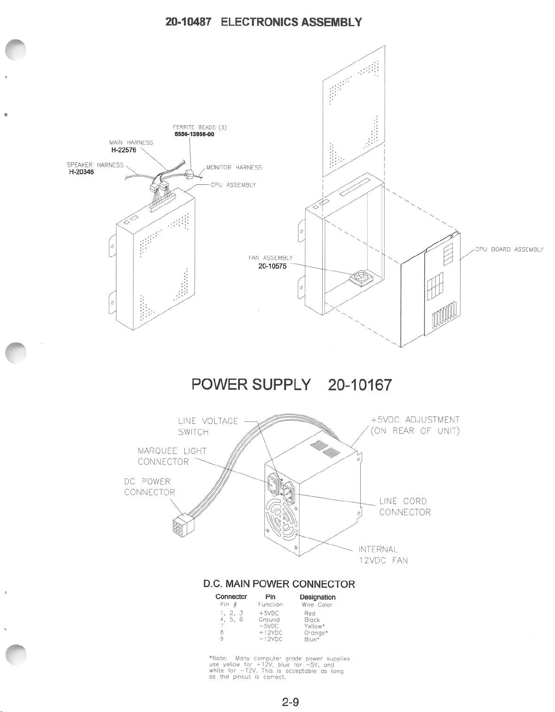
HARNESS
20-10487
FERRITE
5556-13956-00
ELECTRONICS
BEADS
(3)
MONITOR
CPU
ASSEMBLY
HARNESS
FAN
ASSEMBLY
20-10575
ASSEMBLY
CPU
BOARD
ASSEMBLY
MARQUEE
CONNECTOR
DC
POWER
CONNECTOR
POWER
LINE
SWITCH
LIGHT
VOLTAGE
D.C.
MAIN
Connector
Pin //
1, 2, 3
4,
7
*Note: Mony
use
yellow
white for
as
the
SUPPLY
POWER
Function
+
6
for
-12V.
5VDC
Ground
-5VDC
+12VDC
-12VDC
computer
+12V,
This is
5,
pinoutiscorrect.
Pin
grade
blue
acceptable
20-10167
CONNECTOR
Designation
Wire
Color
Red
Black
Yellow*
Orange*
Blue*
power
-5V,
supplies
and
as long
for
+5VDC
(ON
LINE
CONNECTOR
NTERNAL
2VDC
ADJUSTMENT
REAR
OF
CORD
FAN
UNIT)
2-9
Page 40

REAR
DOOR
LOCK
ASSEMBLY
PAD
KEY
LOCK
01-11286
LOCK
01-11287
BRK
BRK
CABINET
SHOWN
FOR
REFERENCE
NUT
1/4-20
4420-01141-00
1/4-20
FLANGRIP
LOCK
PLATE
01-11285
CARRIAGE
4320-01123-20B
X
BOLT
1-1/4
NUT
1/4-20
4420-01141-00
DOOR
FLANGE
BRACKET
01-11291
•PRIMARY
-F
#8-32x11/16
DOOR
20-10350
REAR
4608-01081-11
•DOOR
20"
VENT HOLE COVER
GRIP
CAM
LOCK
PL-HWH
LOCK
DOOR
CAM
ASSEMBLY
UPPER
DOOR
01-8989
LOCK
LOCK
RETAINER
01-7264
A-20281
CAM
PLATE
NUT
4420-01141-00
BOLT'1/4-20xT-1/4
4320-01123-20B
1/4-20
FLANGE
LOCK
01-11285
PLATE
•DOOR
GRIP
CB
LOCK
CAM
BOLT
1/4-20x1-1/4
4320-01123-20B
CB
2-10
Page 41
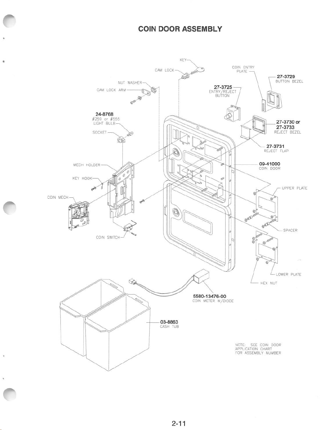
COIN
MECH
MECH
KEY
#259or#555
SOCKET
HOLDER
HOOK
CAM
24-8768
LIGHT
LOCK
BULB
NUT
ARM
WASHER-
COIN
DOOR
ASSEMBLY
KEY-
27-3729
BUTTON
27-3730
27-3733
REJECT
UPPER
BEZEL
or
BEZEL
PLATE
NOTE:
APPLICATION
FOR
ASSEMBLY
SEE
COIN
CHART
DOOR
NUMBER
LOWER
SPACER
PLATE
2-11
Page 42

LINE
CORD
APPLICATION
CHART
\Part
Country
USA
UK
Number
\
5850-
13271-
00
5850-
13272-
00
•
5850-
13273-
00
5850-
13275-
00
•
Italy •
Japan
New
Zealand
Germany
Spain
Denmark
Finland
Holland
Norway
Switzerland
Hungary
Canada
Austria
France
Australia
•
Belgium
Saudi
Arabia
India
Indonesia
•
5850-
13276-
00
5850-
13277-
00
•
•
•
5850-
13278-
00
•
2-12
Page 43

ELECTRO-MECHAN
N^art
Number
Na-soooo-
COIN
ICAL
COI
02 03 06
NDG
07
DOOR
VSSE
or;
09
APPLICATION
MBL
IES
11
14
13
CHART
24
15
17
18
20 22
23
33 38
86
87
Country
USA
Italy
Japan
New
Zealand
Germany
Spain
Denmark
Finland
Holland
Norway
Switzerland
Hungary
Canada
Austria
Australia
Belgium
Saudi
Arabia
India
Indonesia
\
•
•
•
•
•
•
•
•
•
•
•
•
•
•
•
•
•
•
•
2-13
Page 44

RADIKAL
BIKERS
SECTION
THREE
Warning
Failuretoreconnect
installed
and securelytightened may
all
ground
WIRING
wiresorreplace
resultinradio
metal
shields
frequency
3-1
and
covers
interference.
with
each
mounting
screw
Page 45
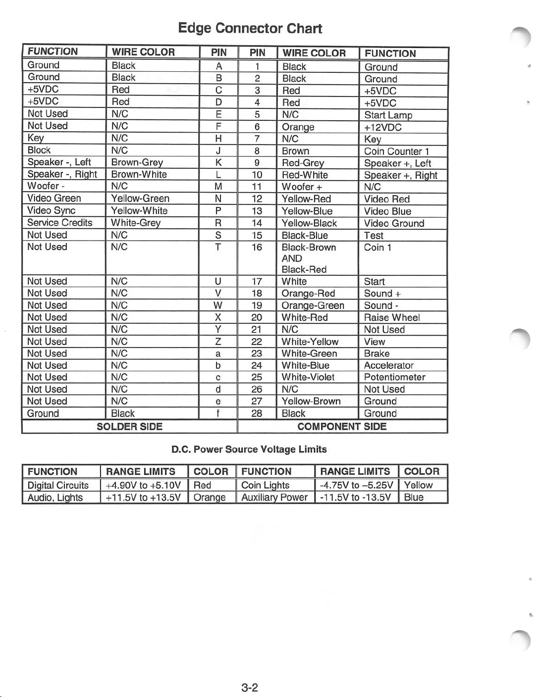
Edge
Connector
Chart
FUNCTION
Ground
Ground
+5VDC
+5VDC
Not
Used
Not
Used
Key
Block
Speaker
Speaker
Woofer
Video
Green
Video
Sync
Service
Not
Used
Not
Used
Not
Used
Not
Used
Not
Used
Not
Used
Not
Used
Not
Used
Not
Used
Not
Used
Not
Used
Not
Used
Not
Used
Ground
-, Left
-, Right
-
Credits
WIRE
Black
Black
Red
Red
N/C
N/C
N/C
N/C
Brown-Grey
Brown-White
N/C
Yellow-Green
Yellow-White
White-Grey
N/C
N/C
N/C
N/C
N/C
N/C
N/C
N/C
N/C
N/C
N/C
N/C
N/C
Black
SOLDER
COLOR
SIDE
PIN
A
B
C
D
E
F
H
J 8
K
L
M
N
P
R
S
T
U
V
w
X
Y
z
a
b
c
d
e
f
PIN
2
3
4
5
6
7
9
10
11
12
13
14
15
16
17
18
19
20
21
22
23
24
25
26
27
28
1
WIRE
COLOR
Black
Black
Red
Red
N/C
Orange
N/C
Brown
Red-Grey
Red-White
Woofer
Yellow-Red
Yellow-Blue
Yellow-Black
Black-Blue
Black-Brown
AND
Black-Red
White
+
Orange-Red
Orange-Green
White-Red
N/C
White-Yellow
White-Green
White-Blue
White-Violet
N/C
Yellow-Brown
Black
COMPONENT
FUNCTION
Ground
Ground
+5VDC
+5VDC
Start
Lamp
+12VDC
Key
Coin
Counter
Speaker
Speaker
N/C
Video
Red
Video
Blue
Video
Ground
Test
Coin
1
Start
Sound
Sound
Raise
Not
View
Brake
Accelerator
Potentiometer
Not
Ground
Ground
SIDE
+
-
Wheel
Used
Used
1
+, Left
+, Right
FUNCTION
Digital
Circuits
Audio, Lights
RANGE
+4.90Vto+5.10V
+11.5V
LIMITS
to+13.5V
D.C.
Power
COLOR
Red
Orange
Source
FUNCTION
Coin
Auxiliary
3-2
Voltage
Lights
Power
Limits
RANGE
-4.75Vto-5.25V
-11.5V
LIMITS
to-13.5V
COLOR
Yellow
Blue
Page 46

»
ENCLOSURE
METAL
CPU
BOARD
CONTROL
PANEL
: :
••:--<
o m
2 33
ASSEMBLY
GND
1
RED/GRY
RED/WHT
BRN/WHi
WHT/BLU
RED
WHT/VIO
"GNDHACCEL
-GNrj
-]
RAISE
+
5VDC
WHEEL
YEL/REP
YFI
/WHT
YEl/BLK
WHT/GRY
YEL/BRN
BLK/BRN
BLK/RED
WHEEL
BLK/BRN
I BLK/RED"
ORG/RED
NC
ORG/GRN
WHT/RED
(NOTE
3)'
GO
I
GO
RAISE
COIN
DOOR
-5VDC
GND IB ~g>
2/
COIN
COIN
COIN
LEFT
RIGHT
COIN
METER
o
>
CO
z
m
H
i
id
z
Q
Si
RVICE
TEST /
VOL + /
VOL - /
SERVICE
GND
VIDEO
GRN
BLU
GND
:•-••";:.:
/
VIDEO
BOARD
ASSEMBLY
SWITCHES
TEST
MODE
VOLUME
VOLUME
SERVICE
MONITOR
CRT
ASSEMBLY
UP
DOWN
CREDIT
D
>
Q
3D
>
MEMORY
BOARD
ASSEMBLY
ACCELERATOR
POTENTIOMETER
NOT
USED
POWER
SUPPLY
WHT/BLU
WHT/ViO
NC~
:.
YEL/BRN
BLK/BLU
jjrg/Md
ORG/GRN
WHT/GRY
YEL/RED
YEL/GRN
YEL/BLU
YEL/BLK
H LINKING CABLE
I TO OTHER GAME
COMPUTER
MANY
POWER
SUPPLIES
YELLOW FOR
ORANGE
AND
THISISACCEPTABLE
LONGASCONNECTOR
PINOUTISCORRECT.
BLUE
-5VDC.
FOR
+12VDC,
FOR
-12VDC.
GRADE
USE
RED/GRY
BRN/GRY
RED/WHT
BRN/WHT
AS
NOTES:
1.
2.
3- BLK/BRN AND BLK/RED COIN WIRES
+CH1
-CHI
-CH2
CONNECT
ALL METAL
WIRE
COLORSDONOT
CONTROL
PANEL
CRIMPED
ARE
PIN T HAS NO
^
&
COMPONENT
TOGETHER
CONNECTION.
LEFT
SPEAKER
PARTS
TO AC
CHANGE
CONNECTORS
AT PIN16ONLY.
GROUND
AT
Page 47

NOTE:
THERE
CHART
FOR
PROPER
LINE
CORD
=OWER
SWITCH
\^_
Bl .-.
r~
i
BLK YEL
WHT
WHT
BLK
RED
O <
O 2
O 3
-O
2 O
3 O
2 O-
3 o
4
-0—i
FUSE GRN YEL
FOR
OPERATION
ON
1. RATINGOFPOWER
2.
FLUORESCENT
3.
VOLTAGE
4.
A.C.
POWER
LAMP
SWITCHONPOWER
TRANSFORMER
OTHER
SUPPLY
ASSEMBLY
SEE
ARE 4 ITEMS THAT
APPLICATION
MUSTBECHANGED
LINE
VOLTAGES:
FUSE
SUPPLY
LINE
FUSE
APPLICATION
VOLTAGE
120
230
FUSE
4A
2A
CHART
SB
SB
RATING
250V
250V
o
>
w
z
m
H
LINE
COMMONING
CO
I
-IN
BLOCK
NEUTRAL
COMMONING
BLK
GRN
WHT
3
BLK
1
O-
GRN
WHT
COLOR
-t.
VIDEO
MONITOR
D.C.
YEL
POWER
SUPPLY
BLOCK
A. C.
POWER
CHASSIS
rrj.
' GRN YEL
I 2
°1
| 3 fj\ _
L^
J 1 I
WHT
J I
CURRENCY
I
ACCEPTOR
1
0pr|0N
>
O
g
>
|
o
I
33
|
>
GRN
WHT
FLUORESCENT
YEL
LIGHT
FIXTURE
Page 48
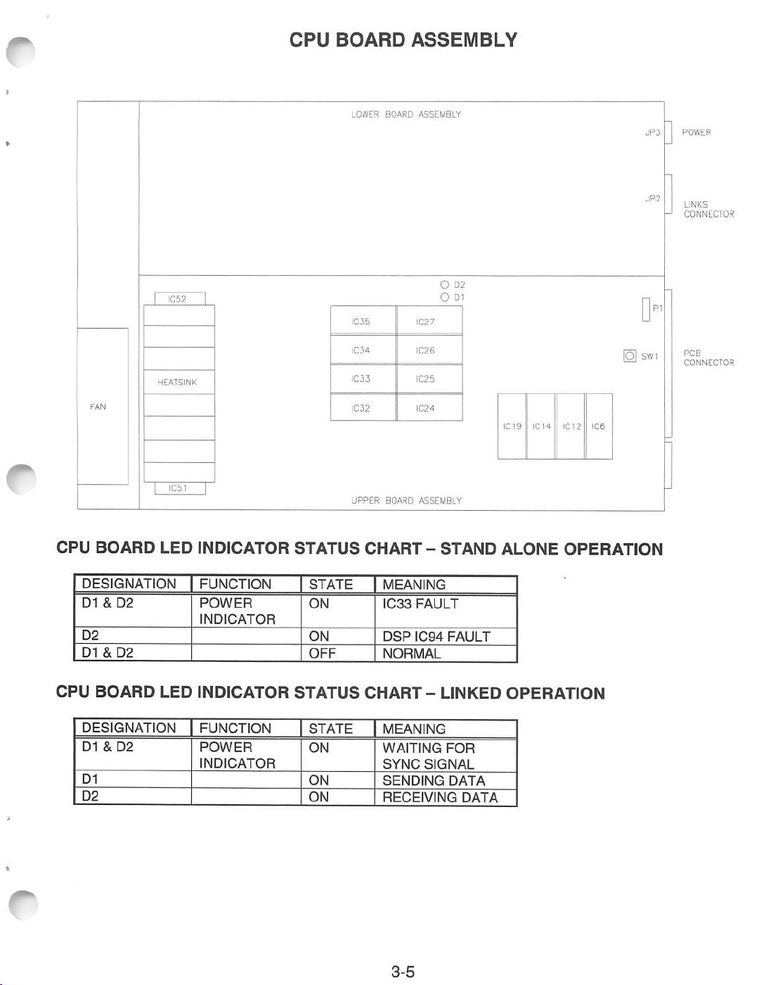
CPU
BOARD
LOWER
ASSEMBLY
BOARD
ASSEMBLY
O D2
O Dl
JP3
-J CONNECTOR
POWER
LINKS
CPU
BOARD
DESIGNATION
D1
D2
D1
CPU
BOARD
DESIGNATION
D1
D1
D2
&D2
&D2
&D2
HEATSINK
LED
LED
INDICATOR
FUNCTION
POWER
INDICATOR
INDICATOR
FUNCTION
POWER
INDICATOR
STATUS
STATE
ON
ON
OFF
STATUS
STATE
ON
ON
ON
BOARD
IC27
IC26
IC25
IC24
ASSEMBLY
1C35
IC34
IC33
IC32
UPPER
CHART-STAND
MEANING
IC33
FAULT
DSP
IC94
FAULT
NORMAL
CHART-LINKED
MEANING
WAITING
SYNC
SENDING
RECEIVING
FOR
SIGNAL
DATA
IC19
IC14
ALONE OPERATION
OPERATION
DATA
IC 1 2
P
SW1
IC6
PCB
CONNECTOR
3-5
Page 49

TM
RADIKAL
BIKERS
SECTION
FOUR
This
game
uses
The
following
Ensure
Discharge
the
Thisistobedone
3.
Store
storeortransport
DO NOT
Doingsowill
Always
completed.
that
power
the
complex
precautions
the
any
supply
electronic
remove
damage
replace
Ensure
TROUBLESHOOTING
A.C.
static
chassis
BEFORE
the
or
ground
electronic
must
powertothe
electricity
assemblies
game
connect
the
electronic
wires,
that
ail
components
be
observed
gameisturned
buildupin
while
the
touchingorhandling
inananti-static
CPU
Board
any
electronic
shields,
ground
and
your
line
cordisconnected
Assembly.
assemblies
safety
and
mounting
4-1
that
are
very
followed
bodybytouching
assemblies
and
covers,
priortohandling
OFF priortoservicing
the
electronic
area.
screws
void
etc.
Anti-static
when
the
are
SENSITIVE
the
toaproperly
assemblies.
bags
the
warranty.
when
maintenance
installed
to
game
the
safety
aretobe
cabinet
and
static
electricity.
electronics.
electronics.
ground
grounded
power
or
service
tightened
stud
outlet.
used
is
firmly.
of
to
ON.
is
Page 50
GAME
1.
DOES
Game
A:
appears
Check
NOT
that
START
completely
the
Power
non-functional;
Switch
has
been
no
audio,noillumination,novideo
turned
ON (on
power
supplyatrearofthe
display.
main
cabinet).
B: Turn
C: Remove the Line Cord.
D: Unlock and open the cabinet door or panel as required to expose the
E: Examine the A.C. fuses on the A.C. chassis or the power supply, and the D.C. fuses on the
F:
2: Video
A:
B:
OFF
the
game
power. Unplug the A.C. line cord.
breaker.
damage.
press
that cabinet wiring
board connectors (refer to Wiring Diagram, Section Three). Inspect
chassis or the electronic equipment shelf.
Fully
game power
game
Unlock
electronics under
(LEDs)ifthere is
The
Power Supply Line Voltage Switch
Test
the line cord, power plug
Verify
the continuity of each wire in the cord. Install the cord at the Power Supply and
firmlyto fully
seat
the
appears non-functional, but currency
A.C.
ON.
seat
the connector into the supply receptacle.
harness
connectors are
plug in the power outlet.
Check the
D.C.
wiring
harness and connectorsiffuse opens the
mustbesettoagree
fully
If
any fuse is
Verify
and open the cabinet door and the game electronics assembly cover. Inspect the
low
light
level
conditions. A
voltageinthe processor
glow
circuits.
Examine
seated
faulty,
that
acceptor
will
This
the
Power
Supply
with
the
and
I.E.C. connectors for breaks or
game
electronics. Ensure
in the corresponding power supply and
wiring
for breaks or damage.
replace it
A.C.
line voltage is present. Turn the
price indicator is illuminated.
be seen
does
not
with
from
the
mean that
an identical fuse.
Light
are as they should be, but it does indicate that the CPU Board is receiving some
the power
Turn
seated
harness connectors in the
OFF
onto
supply.
the game
the
CPU
The power supply fan shouldalso be operating.
power.
Board
same
Ensure
thatthe
connector.
way.
JAMMA
Check
Wire
Harness connector is attached and
the edge connector of the
PCB
fuse
local line voltage.
circuit
Emitting
voltagesorsignals
D.C.
power
and other
or circuit
again.
Diodes
from
fully
wiring
C:
Turn
OFF
the
power
to the
game.
EPROMs and daughter board connectors are properly seated.
CAUTION: DO NOT REMOVE OR INSTALL
DOING
D:
Turn ON the game
SO
WILL
DAMAGE
power.
THE
Using
the 20
voltages present at the Power connector
the Cabinet
E:
Using
Any
reading here indicates that the
Verify
F:
Note
Emitting
G: Enter
the SCREEN
a problem with
Wiring
the 2
that the game runs and completes the
errors and/or failures
Diodes
the
game
Volt
Diagram
A.C.
(Section
setting on a
Three)
digital
supply
found
during
with
the
LED
Indicator Status Chart (Section Three) and note any discrepancies.
menu system by pressing and holding the TEST MODE switch.
ADJUSTMENT
the
PCB or its components. Contact your distributor for
display should read
Open
the
CPU
ANY
CPU
pins.
Assembly
CONNECTOR WHEN POWER IS TURNED ON.
BOARD
Volt
forspecific
voltmeter,
ASSEMBLY
D.C.
setting on a
Adjust
the
+5V
wiring
measure the same
cover.
AND
VOID
digital
sourceifit is necessary. Refer to
information
voltages are unstable and maycontain
power-up
these tests. Compare the
"OK."Ifthe test yields any other result, there is
4-2
self-test sequence
CPU
Check
THE
WARRANTY.
that the
voltmeter, measure
and voltage
D.C.
voltages as above.
limits.
ripple
without
Board
assistance
any errors.
Assembly
The
RAM
with faults.
game
D.C.
or noise.
Light
test
of
Page 51

GAME
CANNOT
BE
PLAYED
1. Game will
A:
Unlock and open the
currency. Check the vault and remove any items that block the path from the mechanism.
B:
Unlock and open the coin door. Check each mechanism by hand to
Remove
Verify
C:
is
D:
Enter the game menu system by pressing and
test
not
accept
currencyortokens
cash
door. Empty the cash box. Inspect the revenue for any counterfeit
and
cannot
be started.
Audio
and
video
ensure
the
mechanism
and
clear the currency path. Reinstall
the
mechanism
that the mechanism is level when the doors are closed. Repair or replace the coin doorifit
bent
or damaged. Adjust the cabinet leg levelersifnecessarytokeep
screens
by pressing the
VIEW
holding
button to the
GAME
the TEST
ASSIGNMENTS
MODE
mechanisms
switch.
screen
One for additional details). Use this screen to confirm the pricing and setup of the mechanism
usedinthe
E:
Verify
2.
Game
accepts
A:
Unlock
Verify
bad coins to
B: Ensure that no loose parts or wires are caught in the hinges, latches, or switch contacts.
game.
that each coin mechanism is operating properly by placing it in a known good unit.
currencyortokens,
but
does
not
start.
Audio
and
video
are
present.
and open the coin door. Check each mechanism by hand to ensure proper mounting.
that each of the release latches is in the closed and locked position. Test known good and
seeifthe mechanism accepts and rejects the currency correctly.
are present.
proper mounting.
and
latch it.
vertical.
Scroll
through the
(refer to Section
C: Inspect to
Check connectors and cables for
D:
Enter the game menu system by pressing and
test
seeifthe external coin door indicators (pricing, flashing arrows, etc.) are illuminated.
wiring
continuity from Filter Board to the coin mechanisms.
screens
by pressing the
VIEW
holding
button to the
GAME
the TEST
MODE
ASSIGNMENTS
switch. Scrollthrough the
screen
(refer to Section
One for additional details). Use this option to confirm the pricing and setup of the mechanism
usedinthe
E: Check for continuity in
game.
each
of the
suspect
switch connections (Common to Normally Open or
Common to Normally Closed). Replace faulty switches (bent levers, broken actuators, etc.).
F:
Verify
that each coin mechanism is operating properlyby placing itin a known good
unit.
4-3
Page 52

CONTROL
PROBLEMS
1. Player controls are intermittent or completely non-functional. Game starts normally.
A:
Unlock
MODE
and open the coin door. Enter the game menu system by pressing and
switch inside the coin door. Press the
VIEW
button to scroll through the menu
holding
the INPUT TEST (refer to Section One for additional details). OK should appear on the screen
these
tests
only when a switch is activated. Use
the
game.
to confirm
the
operation of
each
switch
the TEST
screens
used
to
in
B: Use
the
VIEW button to scroll through the
START, then move the handlebar to its extreme left and right positions. The
be 20 or greater in the far left position and 235 or less in the far right position. The position
will
the
handlebar
changeasthe
indicator
C: Move
D:
Turn OFF the game power. Open the control panel. Grip the handlebar and carefully
panel back on its hinge. Ensure that no loose parts or wires are caught in hinges, latches, or
switches.
E: Check that the cabinet
connected to the control input wires from the joystick wiring
This
F:
game
(Section
Verify
Normally
uses
a non-standard
Three)
for specific wiring information.
continuity in
Closed). Ensure that the control is operating properly by placing in a known good unit.
2. Handlebar calibration is
A:
Unlock
MODE
and open the coin door. Enter the game menu system by pressing and
switch inside the coin door. Press the
the INPUT TEST (refer to Section One for additional details). OK should
only when a switch is activated. Use
the
game.
menu
screenstothe
HANDLE ADJUST test.
NORM
handlebar
to its
exact
wiring
each
of the switch connections (Common to Normally Open or Common to
not
correct (refer to
is moved.
center
position.
The
NORM
value
shouldbe100-150.
is correct for this game. Ensure that the controls are properly
JAMMA
harness
connector. Refer to the Cabinet
steps
A-D above). Game starts normally.
and
the
JAMMA
Wiring
holding
VIEW
button to scroll through the menu
these
tests
to confirm the operation of
appear
on the screen
each
switch
Press
value should
tilt
the
connector.
Diagram
the TEST
screens
used
to
in
B: Use
the
VIEW button to scroll through the
menu
screenstothe
HANDLE ADJUST test.
START, then move the handlebar to its extreme left and right positions. The
NORM
value should
be 20 or greater in the far left position and 235 or less in the far right position. The position
will
indicator
C: Move
the
handlebar
D: Turn OFF the
then
scrolltothe
100-150.
E: Repeat
cycled
F: Unlock
MODE switch inside
the
only
the
steps
OFF
and
INPUT
when
game.
a switch is activated.
changeasthe
to its
game
power, wait ten
HANDLE
C and D
and
ON.
open
the coin door. Enter
TEST
(refer to Section
until
the
handlebar
exact
center
ADJUST
the
NORM
coin door.
is moved.
position.
seconds,
test
as
The
and
turn it ON again.
before.
The
NORM
NORM
value
shouldbe100-150.
Press
value
should
and
hold TEST MODE,
stillbebetween
value remains between 100 and 150 each time power is
the
game
menu
One
Use
systembypressing
Press
the VIEW button to scroll through
for additional details). OK should
these
tests
to confirm
4-4
the
operation of
and
holding
the
menu
appearonthe
each
the
screens
switch
Press
TEST
screen
used
to
in
Page 53

LINKING
PROBLEMS
1. Cannot connect games together. There are no linking cables.
A:Alinking
Contact
B:
This
cableisincluded
your
local
linking
system uses high grade computer type cable
to setupinterconnection.
distributortoobtain
the
special
Each
linking
cable
cable
connects
for
this
for
the game data exchanges.
two
games
gameifitislostormissing.
(one
pair).
Do not substitute other cables or communication wiring without factory authorization.
2. Game functions correctly by itself, but does not recognize other players in linking operation.
A:
Note
and record any error messages that occur
hold the TEST
GAME
ASSIGNMENTS
One cabinet should be set to
before exiting
B: Unlock
Only
assembly
C:
All
MODE
the
revision level is installed, only that linked
D: Turn Off power on cabinets, wait two minutes,
E: Verify
and
use
linked cabinets require the
button on both cabinets. Check that the VERSION displayed on the first menu
same
that
MODE
switch to enter the menu system. Press the
screen. Check that the
MASTER,
the
menu
system.
open the rear door. Verify that the linking cable is
the connector on the right side near the POWER connector on the game electronics
end
panel.
same
for
each
cabinet. Different versions may not be compatible. It
each
linking
cable
is operating properly by placing it in a known
the other to
software version. Unlock the coin door and press the TEST
game
during
self-test. Open the coin door. Press and
LINK
TYPE
setting is different for each cabinet.
SLAVE.
pairs
are
the
same.
and
turn both units on (this
VIEW
button to advance to the
Make sure to save any changes
connected
to the CPU/PCB Board.
screen
does
not matter which
clears
some
errors).
good
unit.
is
3.
o
o
Link
cannotbeestablished
A. Note
hold
and
the
record
TEST
GAME ASSIGNMENTS
One
cabinet should be
before
exiting
gaelta
IcaW
PCB
LOCATION
between
any
error
MODE switch to
screen.
set
the
menu
system.
o
CONNECTOR
o
OF
CONNECTOR
two
messages
that occur during self-test.
enter
the
Check that the
to MASTER, the other to SLAVE. Make
games.
menu
o
o
o
FOR
Linking
system.
LINK
BIKERS
the
•
POWER
coin door.
LINKS
CONNECTOR
o
LINKING
Press
CABLE
cableisconnected.
Open
the
VIEW button to
TYPE setting is different for
suretosave
o
advancetothe
each
any
B. Open the cabinet rear door. Open the CPU assembly cover and observe the activity of the LEDs
near IC27. Compare this activity to the chart in Section Three, Wiring to find any errors with CPU
or linking
cable.
4-5
Press
cabinet.
changes
and
Page 54

AUDIO
1:
Audioisnot
PROBLEMS
heard,
but
videoispresent
and
game
appears
normal
(also
see
Linking
Problems).
->
A: Enter
B:
C: Turn ON the game power.
D:
E:
2:
The audio is distorted, muffled or missing frequencies. A constant low hum may be present.
A:
the
game
menu
system
button to
details).
the
operation.
audible.
Turn OFF the game power. Remove grilles and inspect speakers. Ensure that no loose parts or
wires are caught in speaker cones, terminals, mounting screws, or stuck to the magnets.
voltages
the Cabinet
Using
Any
Verify
Enter the game menu system by pressing and
buttontoscroll
speaker
advancetothe
Use
the
brake
VOLUME
the 2
UP button on the coin door
Repeat
present
Wiring
Volt
this for
at the Power connector pins. Verify the +5V, -5V
Diagram (SectionThree) for specific
A.C.
setting on a
reading here indicates that the supplyvoltages are unstable and may contain
proper
operation
through
connections.
of game
the
by pressing
OUTPUT TEST menu
handle
to highlight
each
Using
channel.
the 20
digital
CPU
Board
menu
screens to the
and
holding
anyofthe
until
Change
Volt
D.C.
voltmeter,
the
TEST MODE switch.
screen
SOUND CHANNEL
there is sufficient channel volume to verify
the levels if
setting on a
(refer to Section
necessarytomake
digital
and
wiring
information and voltage
voltmeter, measure D.C.
measure the same
Assemblybyplacingitinaknown
holding
OUTPUT
the TEST
TEST
MODE
menu.
These tests
Press
One
for additional
menu
selections.
+12V
sources.
D.C.
voltages as above.
ripple
good
game.
switch. Use the
will
the
VIEW
Press
the
game
Refer to
limits.
or noise.
VIEW
verify
the
3:
B:
Turn OFF the game
speaker is
larger
C:
Check
a
thinorhollow
FULL
speaker
thatthe speaker
notbe detected bythe
D:
Check
separate
that the
wires
connected.
E:
Using
the 2
Any
reading
F:
Verify
that each speaker is operating
The
audioismonaural
A:
Verify
that cabinet
JAMMA
B:
Check for shorted or
specific
audio output wires properly.
wiring information.
power.
RANGE
must
rateatleast
sound
cabinet
(notacommon
Refer
to the Cabinet
Volt
A.C.
setting
here
indicates
(it
wiring
broken
Remove
(100 to 10,000 Hz response) and rated for at least 10
wiringisnot
quality
are symptoms of incorrectly phased speakers. This condition
OUTPUT
wiringiscorrect
on a
that the
shouldbestereo).
the
grilles
and check the speakers. Ensure that each small
25 WATTS.
TEST,
return)
Wiring
digital
supply
reversed
for
at oneofthe speakers.
butit
willbeaudible
for
this
game.
each speaker. Ensure that
Diagram
voltmeter,
(Section
measure
voltages are unstable and maycontain
properlybyplacingitinaknown
during
Verify
Three)
voltages
Weak
normal
that the
all
cabinet
forspecific
at the speaker
good
WATTS.
low
frequencies
game operation.
cabinet
wiring
ground
wiring
information.
terminals.
rippleornoise.
unit.
wires
for this game is correct. Ensure that speakers are connected to the
wires.
Refer to the Cabinet
Wiring
Diagram
(Section Three) for
The
and
will
provides
are
4-6
Page 55
VIDEO
PROBLEMS
^
1.
Monitor
A:
B:
C: Examine the
appears non-functional, but audio is present and controls operate as expected.
Open the cabinet to expose the
Monitor.
the
signals are as they
Turn
connectors
connectors in
Inspect the neck of the CRT under
CRT
baseifthere is
voltageinthe
should
OFF the game
are
the
A.C.
power.
fully
seated
same
way. Do
line fuse on the
Video
filament
be, butitdoes
Verify
that the
on the Video
not
operateamonitor
Video
Monitor.
indicate
Monitor
Monitor
Verify
that
A.C.
Power is connected to the
low
light
level
circuits.
that
Video
conditions. A
This
does not mean that other
monitor
circuits
Signal and the Remote Adjustment Board
are
glow
receiving
Board Assembly. Check the other monitor
withoutaRemote
Adjustment
Board Assembly.Ifthe fuse is
will
be seen near
voltages
some
faulty,
Video
or
power.
Board.
replace it
with an identical fuse of the proper voltage and current rating.
D: Ensure that no loose parts or wires are caught on the chassis or the mounting brackets.
E:
Check
that
the
F: Verify that
The
2:
power-up
brightness (intensity)
the
Video Monitor is operating correctly by placing it in a known
self-test
will run,
but
the
and
game
contrast
does
have
not
not
been
appear.
set
to their minimum levels.
good
unit.
No
audioispresent.
A: Note
B: Turn
CAUTION:
THIS
WILL
C: Verify
D: Verify
E: Turn ON
F: Using
G:
and
record any error
pressing
result. This
reports
Ensure
Board
game
.manufacturer
voltages
the
Any
Compare
and
(it
must
OFF
that
Assembly.
DO
NOT
DAMAGE
that
set.
that
the
presentatthe
Cabinet
the
reading
CPU
the
the
Each
the
2 Volt A.C.
messages
holding
test
the
REMOVE
THE
CPU
name,
game
Wiring Diagram (Section
indicates
the
TEST
checks
report OK for
game
JAMMA
ROM
ROM circuit is
Board
someofthe
power.
connector
OR
CPU
BOARD
instruction
Board
Assemblyiscorrect
assembly
power.
Power
setting
that
the
Light Emitting Diode
MODE switch. On
proper
Unlock
INSTALL
AND
setiscorrect
labeled
number
Using
connector
on a digital voltmeter,
supply
that
occur
during self-test. Enter
CPU functions in this
game
operation).
and
open
the
is fully
the
Three)
voltages
seated
ANY
CONNECTOR
VOID
THE
WARRANTY.
for
this
with
the
assembly
for this
and
the
hardware
20 Volt D.C.
pins. Verify
for specific wiring information
are
unstable
states
with
the
first
front
into
the
game.
number
game.
version.
setting
the
+5V
measure
the
CPU
menu
game.
door.
and
Inspect
mating
WHEN
Thereismore
and
Each
CPU
on a digital
source
the
same
may
Indicator
the
game
screen,
Note
connector
contain
check
any
the
POWER
than
the
software
Boardismarked
voltmeter,
if it is
adjustable.
and
D.C.
ripple or
Chart
menu
system
the
RAM
errorsinthe
game
electronics.
of
the
CPU/PCB
IS
TURNED
one
ROM in a
version.
measure
voltage
voltagesasabove.
(Section
limits.
noise.
Three).
RAM
with
Refer
by
test
ON.
the
D.C.
to
4-7
Page 56

3.
4:
Monitor
A:
B:
C: Verify
Game
A:
B:
C:
will
Check
Verify all
Ensure
different resolution
video
operates
Check
Ensure that all the cabinet ground wires are connected, especially at the Video Monitor Chassis.
Move
electrical or magnetic fields are present near some equipment when it is operating
D:
Verify
video signals may
MISCELLANEOUS
not
lock
onto
the
signal
connectors
jumpers
that
that
the
signals
connectors
and
cables
are
set
correctly for this monitor. Refer to Board Configuration (Section
the
Video Monitor
will
result in what
Video Monitor is operating correctly by placing it in a known
may
cause
jitter or vibration with
normally,
and
but
cables
video
the cabinet farther away
that the Video
Monitor
cause
jitter or vibration
and
provideastable
for wiring continuity from
Assemblyiscorrect
appearstobe
some
picture
for wiring continuity from the CPU Board to
from
wavers
or rolls,
machines, appliances, other games, etc.
is operating correctly by placing it in a
with
some
picture,
the
for this
horizontal tearing or
displays; try
has
displays).
CPU
game.
another
dark
colors
Board to
Use
bars,
known
are
missing,
the
of video monitors with
complete
good
brand
of Video Monitor.
uneven
the
Video Monitor.
etc.
Video Monitor.
loss
of sync.
unit. Interlaced
colors,
Very
normally.
good unit (interlaced
Three).
etc.
strong
1:
Marquee lamp is intermittent or non-functional. Game starts and plays normally.
A:
Open the cabinet marquee or attraction panel. Remove the lamp end locks and the fluorescent
tube from the holders. Install a new lamp
B:
Verify
C:
Measure
Three). Check
D:
Ensurethat the Fluorescent
E:
Verify
2.
Game
operates
A:
Check
B: Turn OFF the
that the lamp and starter pins are making good connection
the
A.C.
that the
bottom
voltages
wiring
lamp,
starter, and
intermittently.
and rear ofcabinet for blocked air
game
power. Apply high power vacuum
to the
and connector
Lamp
Ballastisrated
ballast
if
cracks or darkened
Fluorescent
continuity
operate by
Lamp
from
for
flow.
Assembly
the
A.C.
the
placing
Move
cleaner
ends
are
with
their socket contacts.
(Power
Power Chassis to the
local
A.C.
line
voltage
one at a
timeina
game away
to vent holes to remove dust.
C: Open the cabinet to expose the electronics. Ensure that the fan is connected to
3. Error
Messages
appearonthe
screen.
The
game
does
not
start
and
thereisno
found. Clean the tube.
Wiring
Diagram,
Section
Lamp.
and
frequency.
known
from
good
unit.
sources of heat.
wiring
harness.
audio.
A: Check any
B: Call your authorized distributor for help
assembly
identified in the Error Message.
with
4-8
unresolved
screen
messages.
Page 57
WARNINGS
WARNING
USE
OF
DAMAGE!
* Substitute
* For safety and reliability, substitute parts and modifications
components and parts. Failure to do so
*Thisgame is protected byfederal
under federal law. This also applies to
ATARI
facsimiles are manufactured with
NON-ATARI
USE
parts
equipment (or any feature thereof) may be
PARTS
ONLY
ATARI
or modifications may void EMC directive or FCC type
OR
CIRCUIT
AUTHORIZED
copyright,
ATARI
ATARI
MODIFICATIONS
PARTS.
will
void warranty and may result in incorrect and/or unsafe operation.
trademark and patent
logos, designs, publications and assemblies. Moreover, facsimiles of
components.
&
illegal
NOTICES
MAY
CAUSE
acceptance.
are
not recommended. Use only
laws.
under federal law, regardless of whether or not such
SERIOUS
Unauthorized modifications may be
INJURY
OR
ATARI
EQUIPMENT
authorized
illegal
;
NOTE:
Part 15 of the
when
radio
interferencetoradio
interferenceinwhich
When
missingordamaged,
does not contain an
WARNING
Plug
use a cheater
WARNING
A
have
our
playing
epileptic
If
awareness),
We
following
This
equipment
FCC
the equipment is operatedina
frequency
energy
has been tested and
Rules.
andifnot
communications.
case the user
ATARI
ships a game, it is in compliance with
legal
FCC
this
game
intoaproperly
plugtodefeat
very
small
portionofthe
momentary
daily
environment.
certain
condition.
youoranyoneinyour
recommend
symptoms:
lossofconsciousness
These
video
games.
family
immediately
that
consult
parents
dizziness,
label, call ATARI immediately.
disorientation,orconvulsions,
foundtocomply
These
limits
are designed to
commercial
installed
and usedinaccordance
Operationofthis
willberequired
repercussions to the
grounded
the
power
population
outlettoprevent
cord's
grounding
has a
when
persons
People
has
observe
altered
may
who
experienced
your
physician
their
vision,
experience
have
children
DISCONTINUE
with
the
limits
provide
environment.
reasonable
This
with
equipmentina
to correct the interference at his
FCC
regulations. Your label is proof. If the
ownerordistributor
shock
hazards
pin.Donot
condition
viewing
which
certain
seizures
not
had
any
symptoms
before
using
while
they
eyeormuscle
USE
IMMEDIATELY
previous
linkedtoan
cut
may
cause
kindsofflashing
while
watching
seizures
any
video
games.
play
video
twitching,
and
consult
for
a Class A
protection
equipment generated, uses and can radiate
the
instruction
residential
of the
game
and
assure
off
the
ground
themtoexperience
lightsorpatterns
some
may
epileptic
condition
games.Ifyouoryour
involuntary
your
digital
device,
area is
own
proper
against
manual,
expense.
harmful
may
likely
may
result,ifyour
game
pin.
epileptic
kindsoftelevision
nonetheless
haveanundetected
(e.g.
seizuresorloss
child
movements,
physician.
lossofawareness
pursuantto
interference
cause
harmful
to cause
harmful
label
game
operation.Donot
seizures
that
are
present
pictures
experience
the
is
or
in
or
of
NOTICE
Informationinthis
equipment
NOTICE
No
function,
partofthis
publication
ofaphonographic
permission
TM&©Copyright
from
the
manualissubjecttochange
without
notice.
ATARI
reserves
the
design,orcomponentsasprogressinengineeringormanufacturing
recording,
publisher.
FOR
1997
GAELCOS.A.
maybereproducedbyany
nor
maybetransmitted,orotherwise
SERVICE:
CALL
LicensedtoATARI
YOUR
mechanical,
AUTHORIZED
Games
photographic,orelectronic
copied
ATARI
Corporation.
for
DISTRIBUTOR.
All
righttomake
methods
improvements
may
process,orin
publicorprivate
Rights
reserved.
warrant.
the
use,
without
in
form
t
 Loading...