

Page 1

IMPORTANT
4P Version
Operation Manual
Page 2

1
WE ARE HERE TO ASSIST
UNIS SERVICE CENTER
Tel: 972-241-4263
Email:
service@unispartsandservice.com
For parts and service
PONG 4P D&B Manual
Have Questions? Contact us!
When contacting Service, you will need the following information
and the name of your authorized distributor.
11/18/2019
Page 3

PONG 4P D&B Manual
2
CONTENT
IMPORTANT SAFETY INSTRUCTIONS
1. SPECIFICATIONS
....................................................................................................
.......................................................................
2. CONTENTS OF THE ACCESSORY KIT
3. PART NAME
4. SET UP & INSTALLATION
5. HOW TO PLAY
6. GAME OPTION
7. TROUBLESHOOTING
8. MAINTENANCE & INSPECTION
9. OVERALL CONSTRUCTION
.........................................................................................................
....................................................................................
......................................................................................................
.....................................................................................................
............................................................................................
..........................................................................
.................................................................................
...................................................................
3
5
8
10
11
22
24
35
38
54
10. WIRING DIAGRAM
Appendix 1: LED Blacklight Instruction
............................................................................................
................................................................
Appendix 2: Video & Scroll Letters Replacement Instruction
............................
84
88
88
11/18/2019
Page 4

3
Thank you for purchasing PONG 4P. We hope you enjoy the product.
This manual contains valuable information about how to operate and maintain your game
machine properly and safely. It is intended for the owner and/or personnel in charge of
product operation. Carefully read and understand the instructions.
If you need any help during installation and setup please utilize this manual and
troubleshooting guide. If the product fails to function properly, non-technical personnel
should under no circumstance attempt to service the machine. Contact your distributor or
manufacturer for help.
Before use, please read IMPORTANT SAFETY INSTRUCTIONS.
IMPORTANT SAFETY INSTRUCTIONS
To ensure the safe usage of this product, carefully read and
understand these instructions before operating your game.
Save these instructions for future reference.
Use this product only as described in this manual. Other uses not recommended may
cause fire, electric shock or personal injury. Unplug the game from the outlet when not in
use, when moving from one location to another, and before cleaning/servicing.
Explanations which require special attention are indicated by signs of warning. Depending
on the potential hazardous degree, the terms: NOTE, NOTICE, and WARNING are used.
NOTE: A NOTE indicates useful hints or information about product usage.
NOTICE: A NOTICE indicates potential damage to product and how to avoid the problem.
WARNING: A WARNING indicates a potential for product damage or serious personal Injury.
It is important to understand the meaning of the following HAZARD SIGNS before
continuing:
No Touching Hazard:
This part may be hot or can cause electric shock.
Do not touch.
PONG 4P D&B Manual
High Voltage and Shock Hazard:
High voltage can cause electric shock.
Turn off/unplug power before servicing.
High Temperature Hazard:
This part may cause scalding.
Do not touch. Surface may be hot.
11/18/2019
Page 5

PONG 4P D&B Manual
4
Note: The contents of this manual may be updated without notice.
Use the following safety guidelines to help ensure your own personal safety and to help
protect your equipment and surrounding environment from potential damage.
Avoid installing in the following places to prevent fire, electric shock, injury
and/or machine malfunctioning:
Places subject to rain/moisture, or places subject to high humidity.
Places subject to direct sunlight, or places subject to extremely hot or cold
temperatures to ensure that it is used within the specified operating range.
Places where inflammable gas may be present or in the vicinity of highly
inflammable/volatile chemicals or items that can easily catch fire.
On unstable or sloped surfaces. The machine may topple or cause unforeseen
accidents.
Vicinity of fire exits, fire extinguishers etc that may block/prevent safety measures.
IMPORTANT NOTE:
ALL REPAIRS MUST BE DONE TO ORIGINAL MANUFACTURER SPECIFICATIONS.
FAILURE TO DO SO VOID ALL WARRANTIES AND OPERATOR ASSUMES ALL
RISKS.
This product is an indoor game machine. Do not install outdoors.
11/18/2019
Page 6

5
1. SPECIFICATIONS
Rated power supply: AC110V~ 50/60Hz
Min. Power consumption: 180W
Max. Power consumption: 480W
Dimension: Width: 61.00’’ (1550mm)
Depth: 61.00’’ (1550mm)
Height: 116.34’’ (2955mm)
Weight:Approximately 860 lb (390kg)
Part No: P163
Model No: A-439
PONG 4P D&B Manual
NOTICE: After turning off the game, please wait at least 1 minute
before restarting again.
Note: Game specifications are subject to change without notice.
11/18/2019
Page 7

PONG 4P D&B Manual
6
This machine will be divided into a few parts.
Main Cabinet:
Width: 61.00’’ (1550mm)
Depth: 61.00’’ (1550mm)
Height: 32.68’’ (830 mm)
Monitor Assembly:
Width: 63.39’’ (1610mm)
Depth: 11.81’’ (300mm)
Height: 66.34’’ (1685mm)
11/18/2019
Page 8

7
Rotational Marquee & PONG Foam Core Sign:
Width: 47.49’’ (1206mm)
Depth: 7.56’’ (192mm)
Height: 37.13’’ (943mm)
PONG 4P D&B Manual
Note: Game specifications are subject to change without notice.
11/18/2019
Page 9

PONG 4P D&B Manual
8
No.
Part No.
Name
SPEC
Picture
Qty
1
P163-801-000
Power cord
3×16AWG 1.8M
1
2
P163-432-000
Fuse
Φ5×20mm
T6.3A 250VAC
1
3
P163-444-000
Fuse
Φ5×20mm T10A
250VAC
1
4
P163-802-000
Key
171A
2
5
P163-803-000
Manual
D&B
1
6
P163-131-000
Adjust plate A (Short)
δ1.5
1
7
P163-132-000
Adjust plate B (Long)
δ1.5
1
8
P163-362-000
Cross recessed pan
head screw set
M4×10 Color
zinc
2
9
P163-311-000
Standard spring washer
4×1.1h
GB/T93-1987
2
10
P163-101-000
Adjustment weight
White zinc plated
1
11
P163-804-000
Teflon
973UL-S
0.13X25X10
1
No.
Part No.
Name
SPEC
Picture
Qty
1
P163-159-000
Ball
Assembly
2
2
P163-160-000
Paddle
Assembly
4
2. CONTENTS OF THE ACCESSORY KIT
Open the package and make sure all the items are included:
1.1 Following accessories (Package 1)
1.2 Following accessories (Package 2)
11/18/2019
Page 10

PONG 4P D&B Manual
9
2. Accessory KIT
No.
Part No.
Name
Qty
Picture
1
P163-435-000
Cup holder LED ring
1
2
P163-462-000
42MM Stepping motor
1
3
P163-463-000
57MM Stepping motor
1
4
P163-477-000
Motor driver
1
5
P163-461-000
24V Table lifting motor
1
6
P163-134-000
Anti-scratch foam A
10
7
P163-135-000
Anti-scratch foam B
8
8
P163-159-000
Ball
1
9
P163-160-000
Paddle
1
10
P163-482-000
Y axle Toothed belt (XL type)
75.90inX1
11
P163-483-000
X axle Toothed belt (XL type)
74.92inX1
12
P163-484-000
Paddle axle Toothed belt (XL type)
65.63inX1
13
P163-901-000
Jog assembly(with Encoder)
1
NOTE: Part models are subject to change without notice.
11/18/2019
Page 11

PONG 4P D&B Manual
10
Jog
Playfield
Ready for Card Reader
Rotational Marquee Assembly
Cup holder
Speaker
Monitor Assembly
PONG Foam Core Sign
Display
Launch Button
3. PART NAME
Key Components
11/18/2019
Page 12

PONG 4P D&B Manual
11
Leveler
About 0.2 in/5mm
We do not recommend using power tools as they may cause damage.
NOTICE
Make sure the machine is level.
NOTICE
Refer to IMPORTANT SAFETY INSTRUCTIONS (Pg. 3) for items to avoid.
Place the unit on a dry and level surface.
Ventilation openings in the back of the unit must not be obstructed by objects or by
4.1 Transporting the Game
If you need to move the game, adjust the levelers back to an “up” position.
Be careful not to damage the machine during transport.
Always unplug the game before moving.
Keep the machine in upright position during transport.
For longer distance transport, package the game properly to prevent damages.
4.2 Level Adjustment
Leveler
4. SET UP & INSTALLATION
This product is an indoor game machine. Do not install outdoors.
wall.
NOTICE
Install this game on a flat surface. If the game is installed on an unsuitable floor, it could
cause game malfunction.
To secure the game, loosen the nut, utilize wrench to adjust the leveler down until it
touches the floor, lifting the casters off the ground by 0.2 in/5mm. Repeat the same for all
levelers.
11/18/2019
Page 13

PONG 4P D&B Manual
12
Your unit must be leveled to operate properly.
NOTICE
4.3 Play Zone
This machine requires space for playing and for maintenance as shown below.
Leave space around the game upon installation:
Service area: 20 in
11/18/2019
Page 14

13
4.4 Machine Installation
Before processing with assembly assure you have the following tools.
Component Weight:
No.
Name
Picture
1
Allen wrench
2
Spanner
3
Phillips screwdriver
4
Ladder
No.
Name
Picture
Weight
1
Support post
(with a Speaker)
22lb
(10kg)
2
Monitor assembly
135lb
(61kg)
3
Rotational marquee
40lb
(18kg)
PONG 4P D&B Manual
When installing the machine, be very careful and pay attention to ensure that the player
can enjoy the game safely.
Inappropriate handling running counter to the cautionary matters can cause personal injury
or damage to the machine.
Step 1 Guide the Monitor assembly cables to the bottom cable hole of Support post.
Tighten 5 screws and washers on each side to secure the Support posts to Monitor
assembly.
Guide the Speaker cable through the hole indicated by triangle to the Monitor assembly
and connect on each side.
Note: Tighten the screw in the middle of the hole to ensure that it is secured well.
11/18/2019
Page 15

PONG 4P D&B Manual
14
Name
Cross recessed
hexagon screw set
SPEC
M6×20 black
Qty
10
Name
C washer
SPEC
6×1h black
Qty
10
Monitor assembly
Support post
Cable hole
Step 2 Place the Monitor assembly on the cabinet.
Note: The Support post with cable slot should be installed to the brackets between Yellow
player(P2) and Red player(P1).
Notice: Due to the size, weight and balance, it is required that multiple installation
personnel be available for this task.
11/18/2019
Page 16

PONG 4P D&B Manual
15
Name
Cross recessed
hexagon screw set
SPEC
M6×16 black
Qty
4
Metal plate
Monitor assembly
Rotational marquee
PONG foam core sign
Step 3 Utilize Allen wrench to loosen 4 screws indicated by circles; remove the Metal
plates.
Step 4 Place the Rotational marquee on the Monitor assembly. Guide the cable from
Monitor assembly to Rotational marquee and connect.
Tighten 4 screws to secure the Rotational marquee to the Monitor assembly.
Secure back the Metal plates.
Step 5 Utilize dual adhesive to affix the PONG foam core sign to the top Rotational
marquee.
Note: Use of Ladders should be supervised and extreme caution exercised.
11/18/2019
Page 17

PONG 4P D&B Manual
16
Upper
door
Name
Hexagon flange nut
SPEC
M8 color zinc
Qty
4
Name
C Washer
SPEC
8×1.6h
Qty
8
Name
Hexagon bolt
SPEC
M8×55 white zinc
Qty
4
Step 6 Open the Upper doors on Yellow player(P2) side and Green player(P4) side.
Utilize Spanner to tighten 4 bolts and nuts to fix the 4 posts.
Step 6 Locate Yellow player(P2) side. Plug connectors indicated by circle according to cable
color.
11/18/2019
Page 18

PONG 4P D&B Manual
17
Name
Hexagon socket
button head screw
SPEC
M5×8 black
Qty
12
Step 7 Utilize Allen wrench to tighten 3 screws to fix the Metal plate on the cabinet.
Note: The installation method is the same on 4 Metal plates.
Step 8 Locate Green player(P4) side to power on the machine.
Finish!
11/18/2019
Page 19

PONG 4P D&B Manual
18
4.5 Ball and Paddles Placement
Red player(P1)
Red player(P1)
Place the Ball in the
middle. Please assure
that the magnets
stick to the Playfield.
Pay attention to the
direction.
Place the Paddle
in the middle.
Please assure that
the magnets stick
to the Playfield.
Pay attention to
the direction.
11/18/2019
Page 20

PONG 4P D&B Manual
19
4.6 Voltage Conversion (110V to 220V)
Step 1 Locate Green player(P4) side to power off the machine.
Step 2 Locate the power supply on Yellow player(P2) side.
Step 3 Toggle the switch from 115V to 230V on the power supply.
Step 4 Power on the machine.
4.8 Program Update Instruction
4.8.1 Monitor Program Update
4.7 Card Reader Installation Safety Notice
Take precaution to assure that all wiring voltages are confirmed prior to installation
of card reader. All warranties are void if not properly installed resulting in logic board
damage.
Important: This game is pre-wired to AAMA standards. It is highly recommended to utilize
this wiring for Card reader installation.
Step 1 Locate Yellow player(P2) Upper door and open it. Locate the Monitor Program
Update cable.
11/18/2019
Page 21

PONG 4P D&B Manual
20
Step 2 Insert the Memory stick(with new program) to the Monitor Program Update cable.
Step 3 Locate Green player(P4) side to restart the machine.
Step 4 The Monitor will show ‘Installing...’. After the Monitor shows ‘Warning’, the program
is updated. Remove the Memory stick.
11/18/2019
Page 22

PONG 4P D&B Manual
21
Before processing assure you have the following tool.
Kit List:
No.
Part No.
Name
QTY
Unit
Note
1
P163-421-000
SD card
1
PCS
This
Item Sold
Separately
Step 2 Locate Green player(P4) side to restart the machine. The Surrounding light will
become green for about 1 minute.
Note: Displays will show the Program Version(the left 4 characters) and the Music File
Version(the right 3 characters).
Music File
Version
Program
Version
4.8.2 Cabinet Program Update (SD Card)
Step 1 Open Green player(P4) Upper door to locate the SD card Program Update Module.
Insert the SD Card to SD card Program Update Module.
Step 3 The cabinet will restart automatically. Review the new Program version on the
Display. Remove the SD card.
11/18/2019
Page 23

PONG 4P D&B Manual
22
Jog
Orange button
Orange button
5. HOW TO PLAY
Swipe card to join, there will be 5 seconds before the game starts.
Move the jog to control the paddle, press the orange button to launch. (Same function as
the two orange buttons)
There are 4 special areas on the Playfield, whenever the Ball enters these areas, different
play rule applies.
When the Ball hits ‘FULL SPEED’, the Ball will speed up, respectively, when the Ball hits
‘REVERSE CONTROL’, the control of the Paddles will be reversed.
11/18/2019
Page 24
23
Press the
orange button
to launch the
ball!
Turn the jog to
control the paddle
moving left and
right in order to
catch the ball.
Win condition depends on how many players are active:
PONG 4P D&B Manual
1 player VS 3 AI: Any one gets "0" and the game is over.
2 players VS 2 AI: 2 AI have no score and players will be competing with each other.
3 players VS 1 AI: Al has no score. Any one gets "0" and he is out of the game, AI takes
control till the last player wins.
4 players: Any one gets "0" and he is out of the game, AI takes control till the last player
wins.
11/18/2019
Page 25

PONG 4P D&B Manual
24
Next/Prev
Back
Enter/Set
6. GAME OPTION
Enter setting menu
Step 1 Locate the menu panel inside the lower door on Red player(P1) side.
Step 2 Enter the setting menu by pressing the ‘Setting’ button, ‘CONF’ will be shown on the
Display. (Entering the setup will be disabled during game over phase.)
Turn the jog to navigate, press the right orange button to confirm/set, the left orange
button to cancel/exit. (Only active on Red player(P1) side)
Note: Setting menu is accessible even when the game is active.
Reset
Settings
Test
- Volume+
11/18/2019
Page 26

PONG 4P D&B Manual
25
Functions audio related
DATA CLEAR
Clear all data.
Default settings reset
(Press SET to “0” to set)
Free play or not
Clear all data.
(Press SET to “0” to set)
When SERVICE MODE is active, you
will see CONF in the scoreboard by
default. Spinning the JOG will switch
between configuration (CONF) and
checks (CHEC)
BACK exits SERVICE MODE and SET
selects the active option.
6.1 Setting Menu
11/18/2019
Page 27

PONG 4P D&B Manual
26
VALUES: CL
FU
Ny
Re
DEFULT: CL
VALUES: CL
FU
Ny
Re
DEFULT: CL
VALUES: #
RANGE:
0..99
DEFULT: 30
VALUES: #
RANGE:
0..99
DEFULT: 99
VALUES: #
RANGE:
0..99
DEFULT: 99
VALUES: #
RANGE: 0..99
DEFULT: 0
VALUES: #
RANGE: 1..20
DEFULT: 1
VALUES: #
RANGE: 0..99
DEFULT: 0
LOCK COIN
VALUE:#
RANGE:0-03
DEFAULT: 03
This option only applies to units
fitted with a coin mechanism or a
DBV. Choose FREE PLAY or COIN
OPERATED.
This menu is navigated with
NEXT/PREV
JOG changes the parameter.
SET for select.
MERCY TICKET
TICKET FOR
WINNER
EXTRA TIME
TO JOIN
VALUE:#
RANGE:0-60
DEFAULT: 00
11/18/2019
Page 28

PONG 4P D&B Manual
27
Value
Item
Insert Coins/Swipe Card
During Play
Shared Credit
Challenger Enable
LC00
Yes
No
Yes
LC01NoNo
No
LC02
Yes
Yes
No
LC03NoNo
No
REVERSE CONTROL (IC)
ON
OFF
1st“REVERSE CONTROL”
activated
Reverse
Reverse
2nd“REVERSE CONTROL”
activated
Reverse
Normal
3rd“REVERSE CONTROL”
activated
Reverse
Reverse
VALUES: #
RANGE: 3..39
DEFAULT: 05
VALUES: #
RANGE: 0..09
DEFAULT: 05
VALUES: #
RANGE: 0..04
DEFAULT: 02
Game Speed:
0-----0.30m/s
1-----0.45m/s
2-----0.61m/s
3-----0.76m/s
4-----0.92m/s
5-----1.09m/s
6-----1.23m/s
7-----1.38m/s
8-----1.54m/s
9-----1.70m/s
REVERSE
CONTROL
VALUE: ON-OFF
DEFAULT: ON
11/18/2019
Page 29

PONG 4P D&B Manual
28
VALUE: #
RANGE: 0..99
DEFAULT: 01
DIM TIMEOUT
SET ALARM
VALUES: ON-OFF
DEFAULT: ON
VALUES: ON-OFF
DEFAULT: ON
VALUES: ON-OFF
DEFAULT: ON
FULL SPEED
CORNER
REVERSE PADDLE
CORNER
AI
SELF-ADAPTATION
11/18/2019
Page 30

PONG 4P D&B Manual
29
VALUES: #
RANGE: 0..99
DEFAULT: 50
VALUES: #
RANGE: 00.90
DEFAULT: 03
(Note: 00=30s)
AUTO
LEDS, Motors
and Inputs auto
tests. ( Press
SET and BACK to
exit.)
Motors tests.
( Press SET and
BACK to exit.)
Inputs tests.
( Press SET and
BACK to exit.)
(Note: Press Back and SET to move the
Ball up and down to test.)
11/18/2019
Page 31

PONG 4P D&B Manual
30
(Press SET & BACK to exit.)
Blue player JOG
Red player ATARI pressed
Yellow player ATARI pressed
Blue player ATARI pressed
Green player ATARI pressed
Red player LEFT pressed
Blue player LEFT pressed
Green player LEFT pressed
Red player RIGHT pressed
Yellow player LEFT pressed
Yellow player RIGHT pressed
Blue player RIGHT pressed
Green player RIGHT pressed
Red player JOG
Yellow player JOG
Green player JOG
After powering on the machine, the Displays will show the Program Version(the left 4
characters) and the Music File Version(the right 3 characters).
Music File
Version
Program
Version
11/18/2019
Page 32

PONG 4P D&B Manual
31
6.2 IO Chart
Pong 4P D&B IO Chart
Notice [P1:Red player; P2:Yellow player; P3:Blue player; P4:Green player]
Stepping Motors Control Connectors
Encoder
MOT-J1
1.VDD
P1 L&R Driver
ENC J1
1.GND
P1 Encoder
2.Direction
2.SIG B
3.Impulse
3.SIG A
4.GND
4.VCC
MOT-J2
1.VDD
P2 L&R Driver
ENC J2
1.GND
P2 Encoder
2.Direction
2.SIG B
3.Impulse
3.SIG A
4.GND
4.VCC
MOT-J3
1.VDD
P3 L&R Driver
ENC J3
1.GND
P3 Encoder
2.Direction
2.SIG B
3.Impulse
3.SIG A
4.GND
4.VCC
MOT-J4
1.VDD
P4 L&R Driver
ENC J4
1.GND
P4 Encoder
2.Direction
2.SIG B
3.Impulse
3.SIG A
4.GND
4.VCC
MOT-X1
1.VDD
P1 Paddle X-axle
Motor
UART3
1.GND
Side LED control
board
2.Direction
2.VCC
3.Impulse
3.TXD
4.GND
4.RXD
MOT-X2
1.VDD
P2 Paddle X-axle
Motor
UART5
1.GND
Mainboard update
by SD card
2.Direction
2.VCC
3.Impulse
3.TXD
4.GND
4.RXD
MOT-Y
1.VDD
Paddle Y-axle
Driver
PRG
1.GND
Mainboard update
by programmer
2.Direction
2.SCK
3.Impulse
3.SDO
4.GND
4.VCC
EN
1.GND
Stepping Motor
Enable
5.RST
2.Enable
11/18/2019
Page 33

PONG 4P D&B Manual
32
Motor Initial Sensor
Control Panel Button
SENS-J1
1.+5V
P1 L&R Motor
Initial Sensor
BUTTON-J1
1.GND
P1 Control Panel
Button
2.OUT
2.P1 Left Launch
Ball Button
3.GND
3.P1 Right Launch
Ball Button
SENS-J2
1.+5V
P2 L&R Motor
Initial Sensor
4.-
2.OUT
5.-
3.GND
6.-
SENS-J3
1.+5V
P3 L&R Motor
Initial Sensor
INPUT
1.P2 Launch Ball
Button
P2/P3/P4 Control
Panel Button
2.OUT
2.-
3.GND
3.P3 Launch Ball
Button
SENS-J4
1.+5V
P4 L&R Motor
Initial Sensor
4.-
2.OUT
5.P2 Launch Ball
Button
3.GND
6.-
SENS-X
1.+5V
Paddle X-axle
Motor Initial Sensor
7.-
2.OUT
8.-
3.GND
9.GND
SENS-Y
1.+5V
Paddle Y-axle
Motor Initial Sensor
2.OUT
3.GND
11/18/2019
Page 34

PONG 4P D&B Manual
33
Marquee communication
Blacklight/Lifting Motor Detection
UART6
1.GND
Marquee Light
control board
LCD
1.-
Driver board
LIGHT-01 V1.0
2.VCC
2.-
3.TXD
3.-
4.RXD
4.-
UART4
1.GND
Marquee Android
board
5.Lifting motor
detection
2.VCC
6.Marquee
Blacklight
3.TXD
7.VCC
4.RXD
8.GND
SCORE
1.5V
LED display
BAND
1.5V
Playfield inner LED
light effect
2.CI
2.-
3.DI
3.DI
4.GND
4.GND
Coin Lock
OUTPUT1
1.12V
P1-P4 Coin Lock
2.P1 Coin Lock
3.P2 Coin Lock
4.P3 Coin Lock
5.P4 Coin Lock
MENU
1.-
P1 Counter
Assembly
2.Settings
Button
J34
1.P1 Coin
Counter
J35
1.P2 Coin Counter
P2 Counter
Assembly
2.P1 Test Button
2.P2 Test Button
3.GND
3.GND
4.P1 Ticket
Counter
4.P2 Ticket Counter
5.Reset Button
5.-
6.12V
6.12V
11/18/2019
Page 35

PONG 4P D&B Manual
34
Coin Lock
J36
1.P1 Ticket Owed
Light
P1 Tickets
/Insert
Coin/Swipe
Card Signal
J38
1.P2 Ticket
Owed Light
P2 Tickets /Insert
Coin/Swipe Card
Signal
2.P1 Insert
Coin/Swipe Card
2.P2 Insert
Coin/Swipe Card
3.12V
3.12V
4.GND
4.GND
5.P1 Tickets Driver
5.P2 Ticket
Driver
6.P1 Tickets
Feedback
6.P2 Ticket
Feedback
7.12V
7.12V
8.GND
8.GND
J37
1.P3 Coin Counter
P3 Counter
Assembly/Ticke
ts /Insert
Coin/Swipe
Card Signal
J39
1.P4 Coin
Counter
P4 Counter
Assembly/Tickets
/Insert
Coin/Swipe Card
Signal
2.P3 Ticket
Counter
2.P4 Ticket
Counter
3.P3 Tickets Driver
3.P4 Ticket
Driver
4.P3 Ticket Owed
Light
4.P4 Ticket
Owed Light
5.GND
5.GND
6.P3 Insert
Coin/Swipe Card
6.-
7.P3 Test Button
7.-
8.-
8.-
9.P3 Tickets
Feedback
9.-
10.12V
10.12V
BUTTON-J2
1.GND
2.P4 Insert
Coin/Swipe Card
3.P4 Test Button
4.-
5.P4 Tickets
Feedback
6.-
11/18/2019
Page 36

PONG 4P D&B Manual
35
7. TROUBLESHOOTING
7.1 Common Problem
Please confirm that all connectors are secured, all connectors are one way and keyed. If
the connectors don’t slip in easily upon mating, please don’t force them.
Symptom
Possible Cause
Recommended action
Game does not start
Frame assembly
connector is loose.
Check connector.
Faulty frame assembly
Contact UNIS Service.
Power off
Circuit protector changes
power SW to “off”.
Turn on power SW again. If appeared
repeatedly, machine has anomaly.
Please contact UNIS Service.
No sound
Low volume
Turn up the volume.
Loose connectors
Check connector.
Faulty speaker
Check speaker.
Loose audio connector or
faulty cable
Reconnect the audio cable or replace it.
Driver problem
Restart the audio driver.
Ball shaking
The bottom of the Ball or
the Playfield has dirt.
Utilize non-woven fabric with Glassy
water to clean the bottom of the Ball.
Paddle or ball offset
Not enough suction of
magnets
Check whether the playfield is fully
positioned.
Clean the playfield, paddle and ball.
Adjust the rail magnet height upward.
Paddle and ball
crash to offset
Over suction of magnets
Adjust the rail magnet height
downward.
Platform obviously
unbalanced during
moving
DC push rod abnormal
Replace DC push rod.
No light of cup
holder LED ring
LED ring board of cup
holder abnormal
Boot to restart.
Check if the wire is loose.
Replace the LED ring board.
Playfield display
abnormal
Digital board abnormal
Boot to restart.
Replace the digital board.
Movement
mechanism has
obvious noise
Belt or belt wheels
abnormal
Check and adjust the belt tension
strength.
Adjust belt wheel position or replace
belt wheel.
Replace the belt.
11/18/2019
Page 37

PONG 4P D&B Manual
36
Symptom
Possible Cause
Recommended action
Glass playfield
has scratches
There is friction between
the rail and underneath
glass graphics.
Adjust the rail magnet height downward.
Digital board
error of LED
display
The sensor is not working,
the motor is not working.
Check the motor works normally or not, if
not normal, check the driver and
corresponding motor and fuse.
If motor works normally, check the
corresponding sensor.
Replace the fuse, sensor and driver.
LED light strip
not work
Light strip connectors are
loose, fuse blown.
Check the light strip connects properly.
Check the fuse.
Replace light strip.
The motor
doesn’t work
The driver is broken,
causes fuse overload
protection.
Replace the driver or check the motor.
Check and replace the fuse.
Error code
Possible Cause
Recommended action
Motors of Ball X axle
doesn’t work.
Check the connection of motors of Ball X
axle.
Check the motors of Ball X axle.
Malfunctioning Sensor of
Ball X axle
Check the sensor of Ball X axle.
Motor of Ball Y axle
doesn’t work.
Check the connection of motor of Ball Y
axle.
Check the motor of Ball Y axle.
Malfunctioning Sensor of
Ball Y axle
Check the sensor of Ball Y axle.
Motor of Red player(P1)
Paddle doesn’t work.
Check the connection of motor of Red
player(P1) Paddle.
Check the motor of Red player(P1) Paddle.
Faulty Sensor of Red
player(P1) Paddle
Check the sensor of Red player(P1) Paddle.
Motor of Yellow player(P2)
Paddle doesn’t work.
Check the connection of motor of Yellow
player(P2) Paddle.
Check the motor of Yellow player(P2)
Paddle.
Faulty Sensor of Yellow
player(P2) Paddle.
Check the sensor of Yellow player(P2)
Paddle.
11/18/2019
Page 38

PONG 4P D&B Manual
37
Error code
Possible Cause
Recommended action
Motor of Blue player(P3)
Paddle doesn’t work.
Check the connection of motor of Blue
player(P3) Paddle.
Check the motor of Blue player(P3)
Paddle.
Faulty Sensor of Blue
player(P3) Paddle
Check the sensor of Blue player(P3)
Paddle.
Motor of Green player(P4)
Paddle doesn’t work.
Check the connection of motor of Green
player(P4) Paddle.
Check the motor of Green player(P4)
Paddle.
Faulty Sensor of Green
player(P4) Paddle
Check the sensor of Green player(P4)
Paddle.
Out of ticket
Fill the ticket dispenser with tickets.
Wrong connection
Check the connection of Marquee
mainboard cable and Cabinet Mainboard
according to the Wiring Diagram.
Cable quality problem
Replace the cable after checking the
connection.
Mainboard program is not
updated.
Check the program version.
Mainboard or Marquee
mainboard is faulty.
Contact UNIS Service to replace with a
new Mainboard or Marquee mainboard.
11/18/2019
Page 39

PONG 4P D&B Manual
38
We do not recommend using power tools as they may cause damage.
NOTICE
8. MAINTENANCE & INSPECTION
8.1 Safety Check
8.2 How To Clean The Playfield
Step 2 Utilize non-woven fabric with Glassy water to clean the bottom of Ball and Paddles.
We recommend to clean once a week.
Check the points listed below before operating the machine, which is critical for a safe
machine operation.
1. Test game before operation each day.
2. Conduct monthly routine checks of game components to ensure good working
condition.
3. Check the machine regularly for dust and clean when necessary.
Note: Parts and components require preventative maintenance to maintain proper
operation.
Step 1 Make sure that there are no items on the Glass.
Step 2 Locate the Lower door on Red player(P1) side and open it.
Locate the rocker switch indicated by circle.
Press UP to lift the Glass to the highest position.
Step 3 Utilize non-woven fabric with Glassy water to clean the Playfield. We recommend to
clean once a week.
8.3 How To Clean Paddles & Ball
Step 1 Process Step 1 to Step 2 in 8.2 How To Clean The Playfield.
11/18/2019
Page 40

PONG 4P D&B Manual
39
+
=
+
=
8.6 How To Access Movement Mechanism
Before processing assure you have the following tool.
Step 2 Locate Green player(P4) side to power off the machine.
No.
Name
Picture
1
Phillips screwdriver
8.4 How To Replace Wool Felt Pad On Paddle
After repeated use the bottom of the Paddles will get worn off due to friction. We
recommend to replace the Wool felt pad once every 3 months.
Step 1 Remove the wool felt pad from the paddle.
Step 2 Adhere the new wool felt pad to the paddle.
8.5 How To Replace The Teflon Tape On The Ball
After repeated use the bottom of the Ball will get worn off due to friction. We recommend
to replace the Teflon tape once every 3 months.
Step 1 Remove the Teflon tape on the Ball.
Step 2 Adhere the Dual adhesive tape on the Ball; adhere new Teflon tape to the Ball.
Step 1 Process Step 1 to Step 2 in 8.2 How To Clean The Playfield.
11/18/2019
Page 41

PONG 4P D&B Manual
40
Step 3 Locate the Playfield. Loosen four screws indicated by circles.
Step 4 Locate Red player(P1) side. Unplug two connectors indicated by circle.
Step 5 Remove the Playfield, please avoid the Paddles and Ball sticking together.
Step 6 Proceed to the Movement Mechanism.
11/18/2019
Page 42

PONG 4P D&B Manual
41
Kit list (Following accessories)
No.
Part No.
Name
Picture
Qty
1
P163-131-000
Adjust plate A (Short)
1
2
P163-132-000
Adjust plate B (Long)
1
3
P163-362-000
Cross recessed pan
head screw set
2
Before processing ensure you have the following tool.
No.
Name
Picture
1
Phillip's screwdriver
8.7 Belt Tension Adjustment Instruction for Y Axle
If noise is heard from the axles inside the machine, one of the reasons is that the belt has
loosened. Here is the process to tighten the belt.
Step 1 Follow the 8.6 steps to access Movement Mechanism.
Step 2 Locate Ball movement mechanism and place Adjust plate A on it. Utilize Phillip's
screwdriver to tighten two screws to fix the Adjust plate A to the Ball movement mechanism.
Step 3 If the belt is still loose, please remove Adjust plate A and install Adjust plate B to the Ball
movement mechanism. (The installation method is the same as
Step 2.)
11/18/2019
Page 43

PONG 4P D&B Manual
42
Y axle
X axle
Green player
P4
Blue player
P3
Red player
P1
Yellow player
P2
X axle
Adjustment
weight
Adjustment
weight
X axle
Motor side
Paddle
mechanism
Before processing assure you have the following tools.
NO.
Name
Picture
1
Phillips screwdriver
2
Wrench(8mm)
NO.
Code
Name
Picture
1
P163-101-000
Adjustment weight
8.8 Belt Tension Adjustment Instruction for X Axles and Paddle Axles
Kit list:
Step 1 Follow the 8.6 steps to access Movement Mechanism. Locate an axle and Move Y
axle (and Paddle mechanism) to the motor side.
Step 2 Locate one X axle. Place the Adjustment weight in the middle of the X axle.
11/18/2019
Page 44

PONG 4P D&B Manual
43
×
√
Need
to
adjust.
Step 3 Check if the Adjustment weight is slightly above the axle (within 0.04inch). If it is,
don’t adjust the belt; if it touches the axle, adjust the belt.
Step 4 To adjust: Utilize Phillips screwdriver to loosen the screws a bit. Utilize the wrench to
adjust the nut on the side.
Step 5 To adjust: Pay attention to the Adjustment weight when turning the wrench
clockwise. Stop turning the wrench when the Adjustment weight is slightly raised (within
0.04 inch above the axle). If the Adjustment weight is raised too much, the belt will be too
tight.
Step 6 To adjust: Remove the Adjustment weight and tighten the screws in Step 4.
The adjustment method for the 2 X axles and Paddle axles is the same.
11/18/2019
Page 45

PONG 4P D&B Manual
44
Before processing assure you have the following tools.
No.
Name
Picture
1
Phillips screwdriver
2
Allen wrench
No.
Part No.
Name
Picture
1
P163-463-000
57MM Stepping motor
X motor
X motor
Y motor
Paddle motor
Paddle motor
Paddle motor
Paddle motor
Driver
8.9 Motor & Driver Replacement
Step 1 Follow the 8.6 steps to access Movement Mechanism.
8.9.1 X Motor Replacement
Kit List:
Step 1 Locate one X motor. Utilize Phillips screwdriver to loosen 4 screws and unplug the
connector to remove the Motor assembly.
Note: It’s the same method on the 2 X motors.
11/18/2019
Page 46

PONG 4P D&B Manual
45
0.04in
No.
Part No.
Name
Picture
1
P163-463-000
57MM Stepping motor
Gear
Step 2 Utilize Phillips screwdriver to loosen 4 screws to remove the motor from the bracket.
Utilize Allen wrench to loosen 2 screws (turning counterclockwise) to remove the gear from
the motor.
Step 3 Replace with the new motor and install in reverse order.
Note: The distance from motor to gear should be 0.04in(1mm).
Step 4 Refer to 8.8 Belt Tension Adjustment Instruction for X Axles and Paddle Axles in the
Manual to test and adjust the belt.
8.9.2 Y Motor Replacement
Kit List:
Step 1 Locate Y motor. Utilize Phillips screwdriver to loosen 4 screws and unplug the
connector to remove the motor.
11/18/2019
Page 47

PONG 4P D&B Manual
46
No.
Part No.
Name
Picture
1
P163-462-000
42MM Stepping motor
gear
0.08in
Step 2 Utilize Allen wrench to loosen 2 screws (turning counterclockwise) to remove the
gear from the motor.
Step 3 Replace with the new motor and install in reverse order.
Note: The distance from motor to gear should be 0.08in(2mm).
Step 4 Refer to 8.7 Belt Tension Adjustment Instruction for Y Axle in the Manual to test and
adjust the belt.
8.9.3 Paddle Motor Replacement
Kit List:
Step 1 Locate one Paddle motor. Utilize Phillips screwdriver to loosen 4 screws and unplug
the connector to remove the Motor assembly.
Note: It’s the same method on the 4 Paddle motors.
11/18/2019
Page 48

PONG 4P D&B Manual
47
0.04in
No.
Part No.
Name
Picture
1
P163-477-000
Motor driver
gear
Step 2 Utilize Phillips screwdriver to loosen 4 screws to remove the motor from the bracket.
Utilize Allen wrench to loosen 2 screws (turning counterclockwise) to remove the gear from
the motor.
Step 3 Replace with the new motor and install in reverse order.
Note: The distance from motor to gear should be 0.04in(1mm).
Step 4 Refer to 8.8 Belt Tension Adjustment Instruction for X Axles and P1-P4 Axles in the
Manual to test and adjust the belt.
8.9.4 Driver Replacement
Kit List:
Step 1 Locate a driver. Utilize Phillips screwdriver to loosen 2 screws and unplug the
connectors to remove the driver.
Note: It’s the same method on 7 drivers.
Step 2 Replace with the new driver and install in reverse order.
11/18/2019
Page 49

PONG 4P D&B Manual
48
Before processing assure you have the following tools.
No.
Name
Pictures
1
Phillips screwdriver
2
Allen wrench
3
Spanner
4
Socket wrench
上盖板 B
Cover plate B
Platform
assembly
8.9.5 Lifting Motor Replacement
Note: To illustrate conveniently, pictures below have omitted the marquee part, no effect to
actual operation.
Step 1 Utilize Allen wrench to loosen screws on the Cover plate B, each plate has 8 screws,
and take out the plate. It is the same operation on both Red Player & Blue Player position.
Step 2 Utilize Phillips screwdriver to loosen 4 screws on the Platform assembly.
11/18/2019
Page 50

PONG 4P D&B Manual
49
Bottom
connection board
Playfield assembly
Connectors
Plug cover
Step 3 Take out the plug covers, utilize Phillips screwdriver to loosen the screws on the
playfield assembly, unplug 3 connectors, take out the playfield.
Step 4 Utilize Phillips screwdriver to loosen screws on the Bottom connective board and
take out the board. It is the same operation on both Red Player & Blue Player position.
11/18/2019
Page 51

PONG 4P D&B Manual
50
Connectors
Lifting motor assembly
Cupholder
metal plate
Door
plate
Inner plate: Here
are 2 nuts
Under plate: Here
are 8 nuts
Step 5 Utilize Socket wrench to loosen 8 nuts on the under plate and 2 nuts on the inner
plate. It is the same operation on both Red Player & Blue Player positions.
Step 6 Unscrew the Cupholder metal plate, lift it up by hand.
Unplug the connectors to the Lifting motor, and take the Lifting motor assembly out.
11/18/2019
Page 52

PONG 4P D&B Manual
51
Screw
A
Screw
B
Lifting
motor
Push
rod
Step 7 Loosen the screws A & B which fix the motor, take the motor out and
replace with a new motor; tighten the screws back.
Step 8 Adjust new Lifting motor: before fixing it to the cabinet, please plug the connector to
test first; make sure the Push rod is at extreme short position.
11/18/2019
Page 53

PONG 4P D&B Manual
52
Adjusting
bolt
Nut
Side C
Side B
Side A
The height is from
side A to side C, do
not measure it to
side B
×
√
Flatten
√
Not flattens,
needs
adjustment
Step 9 As picture shows below , the height from side A to side C is 10.90 inch.
Utilize the spanner loosen the nuts and turn the adjusting bolt at the same time (clockwise
is to go up, and counterclockwise is to go down), please measure the height first and then
fasten the nuts, to make sure the height is 10.90 inch(277 mm).
Purpose of adjustment: To ensure when the lifting platform lowers down, it flattens on the
cabinet surface at the extreme low position.
Step 10 After fully checking, please install as Step 1 to Step 6 in reverse order.
Note: There may have slight difference or tolerance of each cabinet, the height of 10.90
inch is taken as a reference value; if the Platform does not flattens on the cabinet surface,
slight adjustment of the height is recommended and allowable.
11/18/2019
Page 54

PONG 4P D&B Manual
53
NO.
Name
Picture
1
Phillips screwdriver
2
Allen wrench
3
Ladder
Monitor bracket
Monitor plastic
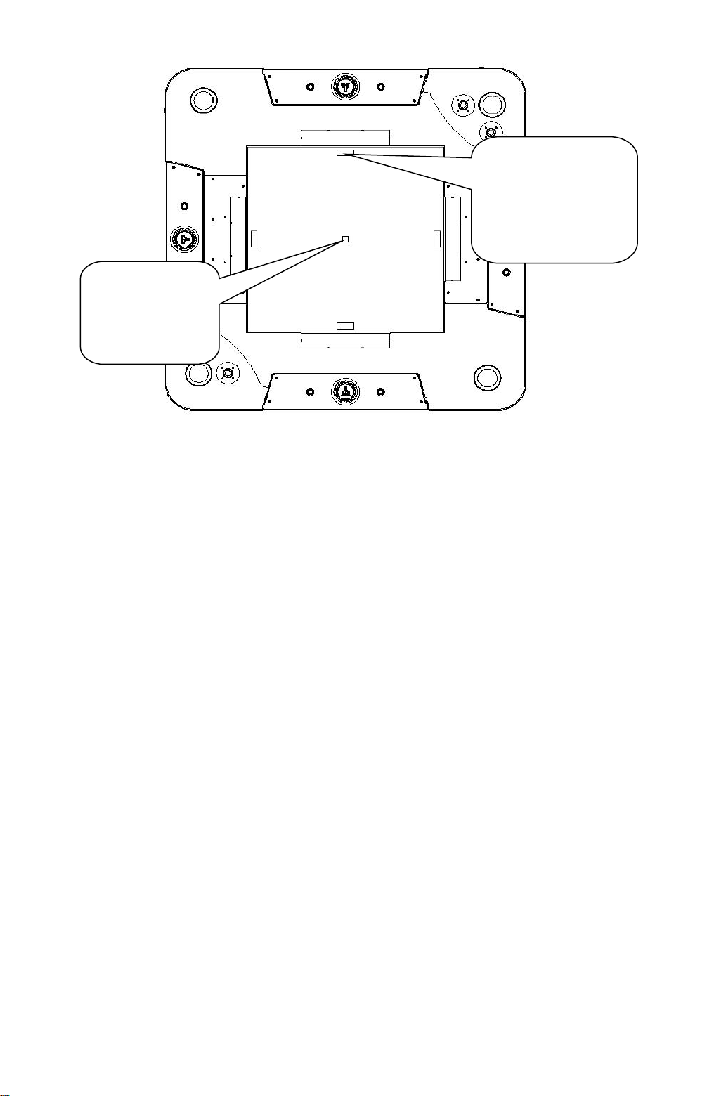
8.10 Marquee Monitor Replacement
Before processing assure you have the following tools.
Step 1 Utilize Allen wrench to loosen 9 screws indicated by rectangles; remove the Monitor
plastic and put aside.
Step 2 Utilize Phillips screwdriver to loosen 4 screws on the Monitor brackets; remove the
Monitor assembly.
Step 3 Utilize Phillips screwdriver to loosen 4 screws on the Monitor brackets; remove the
Monitor. Replace with a new Monitor and install in reverse order.
Note: Use extreme caution and safety with supervision.
11/18/2019
Page 55

PONG 4P D&B Manual
54
9. OVERALL CONSTRUCTION
9.1 Main Cabinet General Assembly
No.
Part No.
Code No.
Name
Qty
1
P163-149-000
20211707R022
Movement bracket A
2
2
P163-150-000
20211707R023
Movement bracket B
2
3
P163-157-000
20211707R013A
Marquee fixing bracket B
2
4
P163-144-000
20611707R002
Surrounding plastic plate B
2
5
P163-155-000
20211707R026
Cup holder LED ring bracket
4
6
P163-156-000
20211707R012A
Marquee fixing bracket A
2
7
P163-467-000
25100080014
Screw cover
16
8
P163-151-000
20211707R024
Frame support
4
9
P163-152-001
20211707R062A
Connector bracket
1
10
P163-147-000
20211707R020
Power plate
1
11
P163-274-000
26000061000
Power supply bracket
2
12
P163-161-000
20611707R045
Waterproof plastic A
1
13
P163-146-000
20611707R004
Surrounding plastic plate D
2
14
P163-102-000
20211707H033
Power supply bracket
1
15
P163-153-000
20211707R025
Lifting button bracket
1
11/18/2019
Page 56

55
No.
Part No.
Code No.
Name
Qty
16
P163-143-000
20611707R001
Surrounding plastic plate A
2
17
P163-162-000
20611707R044
Waterproof plastic B
1
18
P163-158-000
20611707R017
Plastic cover
4
19
P163-148-000
20211707R021
Fan bracket
1
20
P163-141-000
20211707R018
L isolate bracket
4
21
P163-501-000
20311707R001
Bottom connective board
4
22
P163-145-000
20611707R003
Surrounding plastic plate C
2
23
P163-275-000
26000064000
Recovery stick holder
1
24
P163-142-000
20211707R019
R isolate bracket
4
25
P163-154-000
20211707R063
Power pressing plate
2
9.2 Rotational Marquee Assembly
No.
Part No.
Code No.
Name
Qty
1
P163-731-000
20511707R027
Rotational marquee plastic
2
2
P163-264-001
20611707R039A
Rotational marquee light plastic A
2
3
P163-263-000
20211707R092A
Rotational marquee
1
4
P163-257-000
20211707R099
Driving belt wheel
1
5
P163-256-000
20211707R089
Motor bracket
1
22
PONG 4P D&B Manual
11/18/2019
Page 57

PONG 4P D&B Manual
56
No.
Part No.
Code No.
Name
Qty
6
P163-481-000
23404000107
Motor
1
7
P163-269-000
20211707R096
Large axle sleeve
1
8
P163-258-000
20211707R100
Driven belt wheel
1
9
P163-472-000
20106000090
Deep groove ball bearing
1
10
P163-473-000
20106000176
Deep groove ball bearing
2
11
P163-255-000
20211707R093
Rotational bearing bracket
1
12
P163-259-000
20211707R094
Marquee rotational shaft
1
13
P163-464-000
26501000018
A type belt
1
14
P163-260-000
20211707R095
Wiring tube
1
15
P163-262-000
20211707R091
Wiring limited plate
1
16
P163-261-000
20211707R090
Shaft key
1
17
P163-254-000
20211707R088
Rotational base bracket
1
18
P163-268-000
20611707R043A
Top LED mounting plastic
1
19
P163-267-001
20611707R042A
Rotational marquee light plastic D
2
20
P163-266-001
20611707R041A
Rotational marquee light plastic C
2
21
P163-265-001
20611707R040A
Rotational marquee light plastic B
2
22
P163-745-000
20511707R032
PONG foam core sign
1
9.3 Monitor Assembly
11/18/2019
Page 58

PONG 4P D&B Manual
57
No.
Part No.
Code No.
Name
Qty
1
P163-238-000
20211707R082A
Support post
2
2
P163-250-000
20211707R085
Speaker bracket
2
P163-251-000
20211707R098
Speaker inner plate
2
P163-439-000
22806000032
Marquee speaker
2
3
P163-253-000
20211707R087
Pressing plate
1
4
P163-237-000
20211707R081
Monitor marquee
1
5
P163-252-000
20211707R086
Metal plate
2
6
P163-271-000
26000014000
Louver
1
7
P163-239-000
20211707R097
Monitor fixing bracket
4
8
P163-244-001
20611707R037A
Monitor light plastic C
2
9
P163-450-000
21201032018
32'' monitor
2
10
P163-240-000
20611707R031
Monitor long damping foam
4
11
P163-241-000
20611707R032
Monitor short damping foam
4
12
P163-730-000
20511707R026
Monitor plastic
2
13
P163-247-000
20211707R084
Blacklight bracket
2
14
P163-274-000
26000061000
Power supply bracket
1
15
P163-248-000
20611707R033
Long light damping foam
2
16
P163-246-000
20211707R083
Blacklight base plate
1
17
P163-249-000
20611707R034
Short light damping foam
2
18
P163-242-001
20611707R035A
Monitor light plastic A
2
19
P163-245-001
20611707R038A
Monitor light plastic D
2
20
P163-243-001
20611707R036A
Monitor light plastic B
2
21
P163-437-000
22003230002
Blacklight
1
9.4 Movement Mechanism Assembly
11/18/2019
Page 59

PONG 4P D&B Manual
58
No.
Part No.
Code No.
Name
Qty
1
P163-482-000
26504010002
Y axle Toothed belt (XL type)
75.9in
(1928mm)
P163-483-000
26504010002
X axle Toothed belt (XL type)
74.92in x2
(1903mm x2)
P163-484-000
26504010002
Paddle axle Toothed belt (XL type)
65.63in x4
(1667mm x4)
2
P163-170-000
20211707R079
Long track
3
3
P163-515-000
20311707R026
Electrical component supporting
board
1
4
P163-514-000
20311707R025
Supporting board
1
5
P163-181-000
20611707R018
Dust-free cover
1
6
P163-129-000
20211707043A
Fixing plate A
13
7
P163-130-000
20211707044A
Fixing plate B
1
8
P163-131-000
20211707045A
Adjust plate A (Short)
2
9
P163-132-000
20211707046A
Adjust plate B (Long)
2
10
P163-134-000
20611707R046
Anti-scratch foam A
1
11
P163-182-000
20211707R068
Locking plate
1
12
P163-127-000
20211707051A
Connecting bracket
2
13
P163-125-000
20211707027A
Chain mounting plate
1
14
P163-477-000
23429000009
Motor driver
7
15
P163-122-000
20211707022
Track bracket
6
16
P163-128-000
20211707052A
Long sensor SW bracket
6
17
P163-180-000
20211707R067
Wiring plate D
4
18
P163-171-000
20211707R080
Paddle track(Short)
4
19
P163-123-000
20211707024
Wiring plate A
1
20
P163-179-000
20211707R077
Long fixing bar
1
21
P163-124-000
20211707026
Wiring plate C
1
22
P163-133-000
20211707049A
Short fixing bar
12
23
P163-135-000
20611707R047
Anti-scratch foam B
4
24
P163-126-000
20211707041
Small pressing plate
1
9.4.1 Sliding Paddle Assembly(Long)
11/18/2019
Page 60

PONG 4P D&B Manual
59
No.
Part No.
Code No.
Name
Qty
1
P163-469-000
23502000041
Magnet
2x2
2
P163-120-000
20211707004A
Magnet plate A
1x2
3
P163-175-000
20211707R003
Extended bracket
1x2
4
P163-174-000
20211707R066
Bottom bracket
1x2
5
P163-121-000
20211707042
Magnet back plate
1x2
No.
Part No.
Code No.
Name
Qty
1
P163-117-000
20211707002B
Axle bracket
1x2
2
P163-118-000
20211707048A
Wheel shaft
4x2
3
P163-119-000
20611707030
Bearing wheel
4x2
No.
Part No.
Code No.
Name
Qty
1
P163-469-000
23502000041
Magnet
2x2
2
P163-120-000
20211707004A
Magnet plate A
1x2
3
P163-121-000
20211707042
Magnet back plate
1x2
4
P163-176-000
20211707R004
Moving bracket
1x2
5
P163-118-000
20211707048A
Wheel shaft
4x2
6
P163-119-000
20611707030
Bearing wheel
4x2
9.4.2 Sliding Paddle Assembly(Short)
11/18/2019
Page 61

PONG 4P D&B Manual
60
No.
Part No.
Code No.
Name
Qty
1
P163-471-000
23502000049
Magnet
4
2
P163-178-000
20211707R006
Magnet plate B
2
3
P163-177-000
20211707R005
Y axle moving bracket
1
4
P163-119-000
20611707030
Bearing wheel
4
5
P163-118-000
20211707048A
Wheel shaft
4
No.
Part No.
Code No.
Name
Qty
1
P163-463-000
23406000033
57MM Stepping motor
1
2
P163-114-000
20211707021A
Motor bracket B
1
3
P163-116-000
20211707007B
Wheel shaft
2
4
P163-115-000
20211707034A
Idle wheel B
2
5
P163-113-000
20211707033A
Driving wheel
1
9.4.3 Sliding Ball Assembly
11/18/2019
Page 62

61
9.4.4 Y Axle Idle Wheel Assembly
No.
Part No.
Code No.
Name
Qty
1
P163-110-000
20211707018B
Idle wheel bracket B
1x2
2
P163-105-000
20211707032A
Idle wheel A
1x2
3
P163-112-000
20211707055
Idle wheel shaft B
1x2
4
P163-111-000
20611707026A
Bracket shaft
1x2
No.
Part No.
Code No.
Name
Qty
1
P163-108-000
20211707058
Axle plate
1x6
2
P163-105-000
20211707032A
Idle wheel A
1x6
3
P163-107-000
20211707054
Wheel sleeve
1x6
4
P163-109-000
20211707059
Limiting bracket
1x6
5
P163-104-000
20211707017B
Idle wheel bracket A
1x6
6
P163-106-000
20211707047B
Idle wheel shaft
1x6
PONG 4P D&B Manual
9.4.5 X Axle & Paddle Axle Idle Wheel Assembly
11/18/2019
Page 63

PONG 4P D&B Manual
62
No.
Part No.
Code No.
Name
Qty
1
P163-113-000
20211707033A
Driving wheel
1x4
2
P163-172-000
20211707R064
42MM motor bracket
1x4
3
P163-462-000
23406000032
42MM Stepping motor
1x4
No.
Part No.
Code No.
Name
Qty
1
P163-113-000
20211707033A
Driving wheel
1x2
2
P163-173-000
20211707R065
57MM motor bracket A
1x2
3
P163-463-000
23406000033
57MM Stepping motor
1x2
9.4.6 42MM Stepping Motor Assembly
9.4.7 57MM Stepping Motor Assembly
11/18/2019
Page 64

63
9.5 Top Case Assembly
No.
Part No.
Code No.
Name
Qty
1
P163-163-000
20211707R027
Round connective plate
4
2
P163-169-000
20211707R033
Connective plate C
8
3
P163-166-000
20211707R030
Butt plate
2
4
P163-512-000
20311707R011
Outer surrounding board
2
5
P163-511-000
20311707R010
Inner surrounding board B
2
6
P163-510-000
20311707R009
Inner surrounding board A
2
7
P163-502-000
20311707R002
Top case base board
1
8
P163-276-000
26000067000
Plastic joint
74
9
P163-168-000
20211707R032
Bracket
8
10
P163-509-000
20311707R024
Speaker box
4
11
P163-504-000
20311707R004
Control panel L side board
4
12
P163-506-000
20311707R006
Control panel back board
4
13
P163-505-000
20311707R005
Control panel R side board
4
14
P163-164-000
20211707R028
Connective plate A
8
15
P163-167-000
20211707R031
Control panel mounting plate
8
16
P163-165-000
20211707R029
Connective plate B
8
17
P163-508-000
20311707R008
Top case side board(S)
4
18
P163-513-000
20311707R012
Back support board
2
19
P163-507-000
20311707R007
Top case top board
1
20
P163-503-000
20311707R003
Top case side board
4
PONG 4P D&B Manual
11/18/2019
Page 65

PONG 4P D&B Manual
64
No.
Part No.
Code No.
Name
Qty
1
P163-529-000
20311707R023
Corner board
1x2
2
P163-234-000
20211707R054
Corner plate
1x2
3
P163-189-000
20611707R005
Cup holder plastic
1x2
4
P163-235-000
20211707R055
Zinc ring
2x2
5
P163-465-000
20116000197
Rubber ring
2x2
6
P163-190-000
20211707R036
Cup holder
1x2
7
P163-236-001
20211707R056A
Metal cover
2x2
No.
Part No.
Code No.
Name
Qty
1
P163-221-001
20211707R072A
Lock pin
1x4
2
P163-220-000
20211707R051
Upper door
1x4
3
P163-219-000
20211707R050
Side hinge
1x4
4
P163-218-000
20211707R049
Side fixing plate
1x4
5
P163-479-000
25300171001
171 Lock
1x4
11/18/2019
Page 66

65
9.6 Lifting Platform Assembly
No.
Part No.
Code No.
Name
Qty
1
P163-191-000
20611707R011
Damping foam
2
2
P163-187-000
20211707R034
Cover plate A
2
3
P163-186-000
20611707R024
Tempered glass
1
4
P163-188-000
20211707R035
Cover plate B
2
5
P163-194-000
20611707R014
Glass foam C
4
6
P163-189-000
20611707R005
Cup holder plastic
2
7
P163-190-000
20211707R036
Cup holder
2
8
P163-518-000
20311707R013
Top board
1
9
P163-193-000
20611707R013
Glass foam B
2
10
P163-195-000
20611707R030
Glass foam D
4
11
P163-192-000
20611707R012
Glass foam A
2
12
P163-197-000
20611707R026
Glass foam F
2
13
P163-199-000
20611707R028
Metal damping foam A
2
14
P163-196-000
20611707R029
Glass foam E
8
15
P163-198-000
20611707R027
Glass foam G
2
PONG 4P D&B Manual
11/18/2019
Page 67

PONG 4P D&B Manual
66
No.
Part No.
Code No.
Name
Qty
1
P163-204-000
20211707R038
Corner plate
1x4
2
P163-524-000
20311707R020
Base case front frame
1x4
3
P163-521-001
20311707R017A
Base case L board
1x4
4
P163-276-000
26000067000
Plastic joint
14x4
5
P163-526-000
20311707R022
Base case top board
1x4
6
P163-206-000
20211707R071
Base case inner plate
1x4
7
P163-523-001
20311707R019A
Base case back board
1x4
8
P163-522-001
20311707R018A
Base case R board
1x4
9
P163-527-000
20311707R016
Outer coin box
1x4
10
P163-460-000
25501000047
Caster
3x4
11
P163-520-000
20311707R015
Base case bottom board
1x4
12
P163-270-000
26000008000
Cabinet leveller
2x4
13
P163-205-000
20211707R039
Base plate
2x4
14
P163-525-000
20311707R021
Base case front door
1x4
15
P163-479-000
25300171001
171 Lock
1x4
16
P163-478-000
26300000001
Hinge
2x4
9.7 Base Case Assembly
11/18/2019
Page 68

PONG 4P D&B Manual
67
No.
Part No.
Code No.
Name
Qty
1
P163-528-000
20311707R029
Cover board
1x4
2
P163-272-000
26000044000
Counter bracket
1x4
3
P163-208-000
20211707R041
Bottom protective bar B
1x4
4
P163-209-000
20211707R042
Bottom protective bar C
1x4
5
P163-207-000
20211707R040
Bottom protective bar A
1x4
9.8 Control Panel Assembly
11/18/2019
Page 69

PONG 4P D&B Manual
68
No.
Part No.
Code No.
Name
Qty
1
P163-705-000
20511707002
ATARI Logo
1x4
2
P163-138-000
20611707008
Jog shell
1x4
3
P163-137-000
20611707009
Jog
1x4
4
P163-202-000
20211707R014
Rotation shaft
1x4
5
P163-200-000
20211707R037
Decoration plate
1x4
6
P163-519-001
20311707R014A
Control panel board
1x4
7
P163-139-000
20211707013A
Bearing bracket
1x4
8
P163-201-000
20211707R069
Support plate
1x4
9
P163-468-000
20117000296
Coupling
1x4
10
P163-203-000
20211707R070
Encoder bracket
1x4
11
P163-140-000
20211707038
Shaft sleeve
1x4
12
P163-474-000
20106000318
Deep groove ball bearing
2x4
No.
Part No.
Code No.
Name
Qty
1
P163-475-000
20106000336
Deep groove ball bearing
2
2
P163-228-000
20211707R017
Rob shaft C
1
3
P163-223-000
20211707R009
L lifting movement plate
1
4
P163-224-000
20211707R052
Lifting rob A
2
5
P163-226-000
20211707R015
Rob shaft A
4
6
P163-225-000
20211707R053
Lifting rob B
2
7
P163-222-000
20211707R008
L lifting base plate
1
8
P163-461-000
23404010006
24V Table lifting motor
1
9
P163-231-000
20211707R078
Push rob bracket
1
10
P163-227-000
20211707R016
Rob shaft B
1
11
P163-230-000
20211707R074
Plate B
2
12
P163-229-000
20211707R073
Plate A
18
9.9 L Lifting Assembly
11/18/2019
Page 70

69
9.10 R Lifting Assembly
No.
Part No.
Code No.
Name
Qty
1
P163-475-000
20106000336
Deep groove ball bearing
2
2
P163-228-000
20211707R017
Rob shaft C
1
3
P163-233-000
20211707R011
R lifting movement plate
1
4
P163-224-000
20211707R052
Lifting rob A
2
5
P163-226-000
20211707R015
Rob shaft A
4
6
P163-225-000
20211707R053
Lifting rob B
2
7
P163-232-000
20211707R010
R lifting base plate
1
8
P163-461-000
23404010006
24V Table lifting motor
1
9
P163-231-000
20211707R078
Push rob bracket
1
10
P163-227-000
20211707R016
Rob shaft B
1
11
P163-230-000
20211707R074
Plate B
2
12
P163-229-000
20211707R073
Plate A
18
PONG 4P D&B Manual
9.11 Playfield Assembly
11/18/2019
Page 71

PONG 4P D&B Manual
70
No.
Part No.
Code No.
Name
Qty
1
P163-184-000
20611707R010
Brown plastic
4
2
P163-711-001
20511707R004A
Playfield glass
1
3
P163-136-000
20211707028
Connecting plate
4
4
P163-185-000
20611707R019
Glass limited plastic
2
5
P163-183-000
20211707R007
Glass pressing plate
4
No.
Part No.
Code No.
Name
Qty
1
P163-516-000
20311707R027
Frame top board
1
2
P163-517-000
20311707R028
Frame bottom board
1
No.
Part No.
Code No.
Name
Qty
1
P163-212-000
20211707R045
Surrounding light plate C
1
2
P163-211-001
20211707R044A
Surrounding light plate B
1
3
P163-210-001
20211707R043A
Surrounding light plate A
1
4
P163-213-001
20211707R046A
Surrounding light plate D
1
11/18/2019
Page 72

71
9.12 Side Light Assembly
No.
Part No.
Code No.
Name
Qty
1
P163-708-000
20511707R001
Middle light plastic
1x4
2
P163-214-000
20211707R047
Upper light plate
1x4
3
P163-709-000
20511707R002
Right light plastic
1x4
4
P163-215-000
20611707R006
Lower light plastic
1x4
No.
Part No.
Code No.
Name
Qty
1
P163-710-000
20511707R003
Lower plastic
1x4
2
P163-216-000
20211707R048
Lower light plate
1x4
3
P163-217-000
20611707R007
L light plastic
1x4
PONG 4P D&B Manual
11/18/2019
Page 73

PONG 4P D&B Manual
72
No.
Part No.
Code No.
Name
Qty
1
P163-469-000
23502000041
Magnet
2x2
2
P163-278-000
20211707R002
Paddle shell
1x2
3
P163-103-000
20611707020A
Wool felt pad
1x2
No.
Part No.
Code No.
Name
Qty
1
P163-470-000
23502000048
Magnet
4
P163-480-000
40203020002
Teflon tape
0.02
2
P163-277-000
20211707R001
Ball shell
1
9.13 Paddle Assembly
9.14 Ball Assembly
11/18/2019
Page 74

73
9.15 Decals
PONG 4P D&B Manual
11/18/2019
Page 75

PONG 4P D&B Manual
74
No.
Part No.
Code No.
Name
Qty
1
P163-712-000
20511707R006A
Cover decal A
1
2
P163-716-000
20511707R010
Corner plate decal
2
3
P163-714-000
20511707R008A
Control panel decal
4
4
P163-722-000
20511707R017
Base case connective board decal
4
5
P163-726-000
20511707R022
Ball decal
2
6
P163-727-000
20511707R023
Paddle decal
4
7
P163-702-000
20511707K011
Brand R label
7
8
P163-713-000
20511707R007
Cover decal B
1
9
P163-730-000
20511707R026
Monitor plastic
2
10
P163-705-000
20511707002
ATARI Logo
4
11
P163-715-000
20511707R009
Base plate decal
4
12
P163-710-000
20511707R003
Lower light plastic
4
13
P163-709-000
20511707R002
Right light plastic
4
14
P163-708-000
20511707R001
PONG light plastic
4
15
P163-711-001
20511707R004A
Playfield glass
1
16
P163-731-000
20511707R027
Rotational marquee plastic
1
17
P163-745-000
20511707R032
PONG foam core sign
1
11/18/2019
Page 76

PONG 4P D&B Manual
75
11/18/2019
Page 77

PONG 4P D&B Manual
76
No.
Part No.
Code No.
Name
Qty
1
P163-720-000
20511707R015
Counter label
1
2
P163-723-000
20511707R018
Caution label
6
3
P163-729-000
20511707R025
Belt Direction label
6
4
P163-718-000
20511707R013
Fuse label
1
5
P163-735-000
25600000036
Warning label(S)
6
6
P163-741-000
25600000095A
Service label(L)
1
7
P163-737-000
25600000067A
Service notice label
1
8
P163-736-000
25600000042A
Service label 1
1
9
P163-740-000
25600000091
GND label
11
10
P163-704-000
20511707K020
AAMA warning label
4
11
P163-725-000
20511707R021
AAMA label
4
12
P163-744-001
20511707R031A
Wiring label
1
13
P163-706-000
20511707R038
No lubrication label
1
14
P163-728-000
20511707R024
Axle decal
1
15
P163-734-000
25600000017
Power switch label
1
16
P163-739-000
25600000077
Fuse label
1
17
P163-724-000
20511707R019
110V nameplate
1
18
P163-742-000
25600000096A
Service label(S)
4
19
P163-721-000
20511707R016
Warning decal
1
20
P163-738-000
25600000071
110V label
1
21
P163-707-000
20511605A040
Adapter label
2
22
P163-717-000
20511707R011
Recovery stick decal
1
23
P163-719-000
20511707R014
Wiring decal
1
24
P163-701-000
20511707H009
Up-down button label
1
11/18/2019
Page 78

PONG 4P D&B Manual
77
No.
Part No.
Code No.
Name
Qty
1
P163-748-000
20511707R035
Check felt regular label
4
2
P163-749-000
20511707R036
Caution label
14
3
P163-750-000
20511707R037
New wiring label
1
4
P163-746-001
20511707R033A
GMP label
4
5
P163-747-000
20511707R034
Reverse control label
2
6
P163-751-000
20511707R039
110V nameplate(TUV)
1
7
P163-752-000
20511707R040
Recovery stick decal
1
6
7
11/18/2019
Page 79

PONG 4P D&B Manual
78
7
6
8
2
4
51011
12
13
14
9
3
15
16
1
No.
Part No.
Code No.
Name
Qty
1
P163-429-000
21504000002
Encoder
4
2
P163-403-000
22604000006
Micro switch
8
P163-404-000
22401170004
Orange button
8
3
P163-439-000
22806000032
Marquee speaker
2
4
P163-445-000
29711707017
Display
4
5
P163-438-000
22201010003
Light slot
4
P163-440-000
22002020003
BSK6812 light strip
1
6
P163-430-000
22002020002
BSK9822-32 light strip
122.0inx2(3.1mx2)
7
P163-430-000
22002020002
BSK9822-32 light strip
118.1inx2(3mx2)
8
P163-430-000
22002020002
BSK9822-32 light strip
117.3inx2(2.98mx2)
9
P163-411-000
22002018002
RX3535RGB light strip
59.1inX4(1.5mx4)
10
P163-411-000
22002018002
RX3535RGB light strip
79.5inX4(2.02mx4)
11
P163-411-000
22002018002
RX3535RGB light strip
40.9inX4(1.04mx4)
12
P163-430-000
22002020002
BSK9822-32 light strip
268.5in(6.82m)
13
P163-411-000
22002018002
RX3535RGB light strip
51.2inX4(1.3mx4)
14
P163-411-000
22002018002
RX3535RGB light strip
16.9inX4(0.43mx4)
15
P163-435-000
29711707015
Cup holder LED ring
4
16
P163-425-000
22801000085
Speaker
4
9.9 Electrical Components
11/18/2019
Page 80

PONG 4P D&B Manual
79
No.
Part No.
Code No.
Name
Qty
1
P163-477-000
23429000009
Motor driver
7
2
P163-431-000
26503020027
Chain
1
3
P163-420-000
29711707009B
Mainboard
1
4
P163-181-000
20611707R018
Dust-free cover
1
5
P163-428-000
22803010011
Amplifier 2.0
1
6
P163-424-000
22803010010
Amplifier 2.1
1
7
P163-452-000
29711707014
Driver
1
8
P163-443-000
22807000003
Audio isolator
1
9
P163-415-000
21702000022
Audio board
1
P163-416-000
23305000022
Audio cable
2
10
P163-462-000
23406000032
42MM Stepping motor
4
11
P163-463-000
23406000033
57MM Stepping motor
3
12
P163-482-000
26504010002
Y axle Toothed belt
(XL type)
75.9inx1
(1928mmx1)
13
P163-483-000
26504010002
X axle Toothed belt
(XL type)
74.92inx2
(1903mmx2)
14
P163-408-000
21503000055
Sensor SW
6
15
P163-484-000
26504010002
Paddle axle Toothed belt
(XL type)
65.63inx4
(1667mmx4)
16
P163-406-000
22702010025
Fan
1
P163-410-000
22702000010
Fan net
2
1
2
14
3
5
6
7
8
9
10
10
11
11
15
13
14
11
14
10
10
12
16
4
13
11/18/2019
Page 81

PONG 4P D&B Manual
80
No.
Part No.
Code No.
Name
Qty
1
P163-436-000
29711707018
Light belt driver
1
2
P163-434-000
21603000027
AC adapter
2
P163-412-000
23301040022
Cable joint
2
3
P163-427-000
21714000148E
Fuse board(green holder)
1
4
P163-418-000
21602000106
Power supply
1
5
P163-405-000
21602000105
Power supply
1
6
P163-426-000
21714000148D
Fuse board(green holder)
1
7
P163-407-000
23201000005
Filter
1
P163-444-000
21901000013
Fuse
1
No.
Part No.
Code No.
Name
Qty
1
P163-419-000
29711006008
PCB
4
2
P163-446-000
22601000044
Lifting switch
1
3
P163-441-000
23309000280R
Cable set
1
1
2
3
4
5
6
7
1
2
3
11/18/2019
Page 82

PONG 4P D&B Manual
81
No.
Part No.
Code No.
Name
Qty
1
P163-461-000
23404010006
24V Table lifting motor
1
2
P163-409-000
23000000005
Counter
8
3
P163-414-000
29791400001
POT connect plate
1
P163-442-000
22403000001
POT knob
1
4
P163-413-000
22402030002
Button(green)
1
P163-417-000
22402050001
Button(black)
4
P163-423-000
22402010002
Button(red)
4
5
P163-422-000
51306000020
Quadraphonic mixing module
2
6
P163-421-000
21107010038
TF card
2
7
P163-451-000
41300000007
Recovery stick
1
8
P163-490-000
29790700002
Ticket convert board
4
5
6
1
2
3
4
Front side
Back side
5
6
7
8
11/18/2019
Page 83

PONG 4P D&B Manual
82
No.
Part No.
Code No.
Name
Qty
1
P163-406-000
22702010025
Fan
1
P163-410-000
22702000010
Fan net
1
2
P163-481-000
23404000107
Motor
1
3
P163-401-000
21608000010
Conducting ring
1
4
P163-436-000
29711707018
Light belt driver
1
5
P163-427-000
21714000148E
Fuse board(green holder)
1
6
P163-453-000
21902000024
Fuse holder
2
P163-432-000
21901000015
Fuse
2
7
P163-418-000
21602000106
Power supply
1
8
P163-450-000
21201032020
32'' monitor
2
9
P163-437-000
22003230002
Blacklight
1
10
P163-448-000
21107210028
Marquee mainboard
1
P163-433-000
23304010038
Extended cable
1
1
2
3
4
5
6
7
8
9
10
Refer to next page.
11/18/2019
Page 84

PONG 4P D&B Manual
83
No.
Part No.
Code No.
Name
Qty
1
P163-449-000
21107080011
VGA splitter
1
2
P163-447-000
23307000023
15PVGA video cable
1
3
P163-402-000
23307000001
15PVGA video cable
2
No.
Part No.
Code No.
Name
Qty
1
P163-487-000
20211707Y1420
32’’ Monitor mainboard
1
2
P163-488-000
20211707Y1421
32’’ Monitor power module
1
3
P163-489-000
20211707Y1422
32’’ Monitor 5-key board
1
1
2
3
3
1
2
3
11/18/2019
Page 85

PONG 4P D&B Manual
10. WIRING DIAGRAM
L shoot button10R shoot button
L shoot button
R shoot button
L shoot button
R shoot button
L shoot button
R shoot button
8
PPSR-PX-10
A0A0
A0
10
20
A0
10
20
A0
10
J124
P
6
6
C
12345
20
P
12345
6
12345
6
J17
C
A09192
6
XH/6P
J105
A0E504020
P
12345
6
12345
6
J14
20
7
P
12345
6
12345
12345
6
C
J15
A09192
12345
C
J16
A01020
to update program
PPSR-PX-57
6
PPSR-PX-09
A0
10 10
20 20
12345
6
12345
6
GND
BUTTON-J1
Red player Start button
Red player L shoot button
Red player R shoot button
Direction
Pulse
5
GND
MOT-J1
123
4
123
4
XH
1020A0
91
XH/6P
123456789
123456789
INPUT
Yellow player Shoot button
A0×2
PPSR-PX-48
Wiring cap
A0
10
91
XH/9P
PRG
GND
Blue player Start button
Blue player Shoot button
Green player Start button
Green player Shoot button
Yellow player Start button
Direction
Pulse
GND
MOT-J2
123
4
123
4
XH
3040A0
A0E504020
12345
12345
SCK
SDO
GND
E
XH
123
123
5V
GND
UART6
RST
VCC
Direction
Pulse
GND
MOT-Y
EN
123
4
1
123
4
1
XH
A0
91
92
12345
90M
20M
90M
20M
TXD
Enable
2
2
90
VCC
GND
P1
12345
12345
20
To mainboard program update
20
TO PPSR-PX-00-04-B1
To Marquee
6
C4501HM
J106
E
E
90M
20M
20
E
90M
20M
XH/4P
XH/4P
4
123
4
4
123
4
5V
GND
UART4
TXD
RXD
RXD
Direction
Pulse
GND
MOT-X2
123
4
123
4
XH
XH
9394A0
A0ME30M
50M
40M
20M
PPSR-PX-16
12345
12345
CN1
VR
50K POT
TXD
RXD7
CD9205
6
7
6
40A0E
XH/7P
40A0E
HM
123
4
123
4
40A0E
C2521HF-4P
Audio port
Audio isolator
PPSR-PX-56A
40A0E
20
XH/4P
123
4
123
4
5V
GND
UART5
TXD
RXD
Audio port
M4-MB.PCB
Direction
Pulse
GND
MOT-X1
123
4
123
4
XH
9596A0
A0ME30M
50M
40M
20M
J25
20M
20M
PPSR-PX-15
CON1
AUDIO 1
Direction
MOT-J3
123
123
60
12345
12345
12345
12345
R soundtrack1
R soundtrack2
R
AUDIO2
Pulse
50
A0
5559/6P
6
6
5557/6P
A0ME30M
50M
40M
A0ME30M
50M
40M
XH
6
6
GND
GND
L soundtrack1
L soundtrack2
to Marquee speaker
123
4
J113
C4501HM
905096
95
AUDIO V1.0
AUDIO2
Red player Speaker
Yellow player Speaker
Blue player Speake r
Green player Speaker
+
-
+
-
+
-
+
-
90
50
90
50
1
1
J26
90
50
90
50
90
50
1
2
2
1
2
1
2
P
P
P
2
1
2
C
J27
90
50
P
1
2
1
2
C
J28
C
J29
C
96
95
96
95
PPSR-PX-04A
TO PPSR-PX-00-04-C1
to Marquee black light
1
2
J103
C4501HM
A0P
20P
W
28
A0
90×2
28
905096
95
XH
L-
OUTR
A0
XH
XH
1
2
123
123
1
2
J2
R-
R+
24V
GND
GND
Audio input L
Audio input R
IN1
123
123
XH
20A090
50
123
123
L+
OUTL
HW-713
2.0 Amplifier
50×2
24V+
GND-
SPKL+
WM-024GT
2.1 Amplifier
Audio input R
GND
Audio input L
IN
123
123
20A090
PPSR-PX-47A
12V
5V-IN
1
1
20P
GND5VGND
2
2
VH
A0P
12V
GND
12V-IN
LCD
123
4
1234567
1234567
123
4
5557/4P
40P
A0P
40P
A0P
GND
4
4
XH
Direction
Pulse
GND
MOT-J4
123
4
123
4
XH
70
80
A0
Wiring cap
96×2
95×2
90P
A0P
SPKL-
SPKR-
SPKR+
XH
VCC
GND
Marquee black light
Platform motor detection
8
8
XH/8P
BA020
10
3.3V
Platform motor detection
GND
Marquee black light
J3
123
4
123
4
BA020
10
PPSR-PX-49
PPSR-PX-54
A0P
20P30P
VH
1
2
1
2
J2
24V
LED
MOT+ IN
MOT- IN
MOT+ OUT
24V1
123
J1
XH
MOT- OUT
GND
24V
GND
J4
123
4
4
123
4
234
VH
5557/4P
A0P
60P
10P
60P
10P
PPSR-PX-50
6
XH
6
VRPCB
RW
Pong Main V2.1
8
PPSR-PX-00-01C
=CurrentDate
PONG 4P D&B Wiring Diagra m 1
Date:
Name:
Version:
Universal Space
Amusement machine
UNIS
7
6
Driver
LIGHT-01 V1.0
60P
10P
5
1
2
C4501HM
1
2
J101
60P
10P
C4501HF
PPSR-PX-05
Red driver
123
PUL+
PUL-
M542C
ACC
GND
12345
30P
A0P
PPSR-PX-07
J03
4
3
PPSR-PX-08
Red player motor
2
1
84
11/18/2019
PPSR-PX-06
M
light 5V power
To Machine surrounding
2
1
5559/2P
J125
20
TO PPSR-PX-00-02-A2
VH
2
2
1
2
J5
5V
GND
GND
P1
4
4
P
40Q
40Q4040
A0
Example 2 0 m
Note: Wire color and wire size is shown in code.
D D
Platform lifting motor 2(Blue Player)
12V
4
FAN
Fan
To Marquee 12V power
20
TO PPSR-PX-00-02-A1
2
5559/2P
A0
1
J6
5V
16
77
16
A0
50
Color of the wire: 20 means red
Size of the wire: m means AWG24 UL1015
A0
1
2
P
123
1
2
J102C
C4501HM
C
J85
A0P
40P
A0
40
PPSR-PX-54
Marquee12V
TO PPSR-PX-00-02-D1
40P+40
2
J2
GND
15
11
10
1717
15
11
10
A0
unit mm
AWG18 UL1015
AWG16 UL1015
AWG14 UL1015
AWG18 UL1007
AWG16 UL1007
Q
violet
grey
white
3
A0P+A0
TO PPSR-PX-00-03
GND
GND
GND
12V/4=F3
12V/6=F2
12V/2=F4
2424
2
±10
±20
±30
±40
±50
:
Tolerance
0~1000
1001~2000
2001~3000
3001~4000
4001~5000
scale
AWG30 UL1015
AWG28 UL1015
AWG26 UL1015
AWG24 UL1015
AWG22 UL1015
AWG20 UL1015
jkLmnopqr
Wire size code
AWG30 UL1007
AWG28 UL1007
AWG26 UL1007
AWG24 UL1007
AWG22 UL1007
AWG20 UL1007
JKLMNOP
Wire size code
1
black
pink
light green
sky blue
shield layer
ABCDEFGHI
brown
red
orange
yellow
green
blue
123456789
Wire color code
10A0A0
90
A0
A0
A0
4
1
2
DIR-
DIR+
MF+
MF-
B-B+A-
A+
6
50A060
20
50A060
20
123
4
C
123
4
P
50
A0
60
20
M
90
A0
A0
123
4
1
2
DIR-
PUL+
PUL-
DIR+
MF+
MF-
M542C
ACC
GND
B-B+A-
A+
12345
6
Yellow driver
50A02050
60
50P
A0P
A06020
123
4
C
J04
123
4
P
50
A0
60
20
M
Yellow player motor
90
A0
A0
1
2
123
4
DIR-
PUL+
PUL-
DIR+
MF+
MF-
M542C
ACC
GND
B-B+A-
A+
12345
6
Y driver
7010602070P
A0P
701060
20
123
4
C
J05
123
4
P
4-cord cable
50
A0
60
20
M
Y motor
60P
10P
80P
J114
80P
PPSR-PX-52A
10P
80P
A0P
C
123
4
J98
123
4
P
80P
60P
10P
A0P
PPSR-PX-51
10P
SW-DPDT
10P
60P
90
A0
A0
123
4
1
2
DIR-
PUL+
PUL-60DIR+
MF+
MF-
M542C
ACC
GND
B-B+A-
A+
12345
6
Yellow player X drive r
50A0602080P
A0P
50A060
20
123
4
C
J06
123
4
P
50
A0
20
M
Yellow player X motor
60P
10P
A0P
C4501HM
123
4
123
4
C4501HF
60P
10P
A0P
Wiring cap
Platform motor control switch
A A
90
M542C
Red player X motor
123
PUL+
PUL-
ACC
GND
12345
A0P
J07
A0
4
1
2
DIR-
DIR+
MF+
MF-
B-B+A-
A+
6
Red player X driver
50A0602080
50A060
20
123
4
C
123
4
P
50
A0
60
20
M
90
A0A0A0
A0
123
4
1
2
DIR-
PUL+
PUL-
DIR+
MF+
MF-
M542C
ACC
GND
B-B+A-
A+
12345
6
Blue player driver
10P
A0P
50A060
20
50A060
20
123
4
C
J08
123
4
P
50
A0
60
20
M
Blue player motor
M
10P
60P
C4501HF
1
2
1
2
J99
C4501HM
60P
10P
Platform lifting motor 1(Red Player)
Filter
L
E
PLUG
B B
N
90
A0
123
4
1
2
DIR-
PUL+
PUL-
DIR+
MF+
MF-
M542C
ACC
GND
B-B+A-
A+
12345
6
Green player driver
50A060
20
60P
A0P
30P
50P
70P
80P
90P
10P
60P
123456789
J10
123456789
30P
50P
70P
80P
90P
10P
50A060
20
123
4
C
J09
123
4
P
50
A0
60
20
M
Green player motor
60P
10P
1
2
C4501HF
1
2
J100
C4501HM
80P
A0P
60P
10P
PPSR-PX-18
PPSR-PX-17
FUSE BOARD 02(V1.0)
MOTOR P1
MOTOR P2
30P
50P
F1F2F3F4F5
F1F2F3F4F5
FUSE F5A/250V
24V/350W
60P
MOTOR Y
AMP
MOTOR X
MOTOR P3
MOTOR P4
70P
80P
90P
10P
60P
F6
F6
80P×2
80P×2
80P×2
24V
24V
24V
AC L
Power supply
PPSR-PX-02
10P
FUSE
T6A
Power switch
SW DPST
10P
45Q
Noise filter
Earth
60P
C C
45Q
Wiring cap
HM
HF
10P
1
1
45Q
2
2
60P
3
3
J01
PPSR-PX-03
20P
A0P
40P
A0P
40P
A0P
12345
6
P
J11
12345
6
1
C
J115
A0P
A0P
40P
40P
20P
A0P
20P+20
A0P+A0
A0P
A0P
A0P
A0P
A0P
A0P
A0P
P
1011121314
1011121314
C
A0P
A0P
A0P
A0P
A0P
A0P
A0P
MAIN BOARD12V
MAIN BOARD 5V
Marquee 5V
A0P
A0P
40P
40P
20P
A0P
20P
A0P
VH
124
3
1
2
1
VH
123
4
1
2
GND
Power supply
J02
1
J3
J4
5V
5V
12V
12V
GND
P2
123
123
4
P4
123
123
4
A0Q
A0Q
40O
A0O
A0O
20O
JHD5084HP/4P
PS-6301-09
Green player control panel GND connector
FRD2-156
45Q
10P
45Q
60P
123
HM
TO PPSR-PX-00-02-A3
Output AC100-240V
J1
GND
Fuseboard01(V1.0)
A0P×2
A0P×2
A0P×2
A0P
GND
GND
GND
Earth
AC N
90P
50P
A0P
60P
Page 86

PONG 4P D&B Manual
8
7
6
5
+12V
Coin signal
123456789
J1
50
6020A09050
12345
12345
J55
6020A09050
20
J43
20
PPSR-PX-31
24×3
Wiring cap
1020405024
A0×2
123456789
J35
123456789
1020405024
A0
PPSR-PX-24
Ticket signal
Lock coin signal
6020A0
6
HF
6
C4501HM
A0
A0×2
45Q45Q
123
123
A0
30
30×2
GND
Ticket drive
90
AAMA C5030HF-3X3P
123
4
J2
6020A0
90
60×220A0×2
J3
123
123
J1
123
Ticket converted board
TICK-CH.PCB
123
J56
24
Coin counter
HX50300-4RF
90×2
4
80
VH
4
1
2
J58
J57
C
4
4
24
70
24
VH
8030A0
Ticket counter
GND
80
80
A0
1234567
1234567
PPSR-PX-44
S1
S2
S3
Settings
Test button
Reset button
1020A0
91
P
8
8
C
91
102040A060
5559/3P
5557/3P
60
809170
5559/12P
101112
1234567
J39
2450A0
8
C
92
30
80
101112
5557/12P
80×230917060
+12V
Coin signal
123456789
J1
50
6020A09050
12345
12345
J55
6020A09050
J44
PPSR-PX-32
24×3
Wiring cap
1020405060
10
24
A0×2
123456789
J36
123456789
1020405024
A0
20
20
Ticket signal
60A090
6
6
A0A0
A0×2
123
123
GND
Ticket drive
AAMA C5030HF-3X3P
HF
123
4
J2
6020A0
90
C4501HM
60×220A0×2
90×2
J3
123
123
J1
123
Ticket converted board
TICK-CH.PCB
123
J61
80A024
30
45Q45Q
5559/3P
Coin counter
HX50300-4RF
PPSR-PX-46
4
80
80
VH
4
4
4
1234567
1234567
1
2
J63
J62
C
24
70
24
VH
5557/3P
80
70
5559/12P
101112
1234567
101112
J40
5557/12P
2450A0
80×23070
60
30×2
93
30
80
+12V
Coin signal
Ticket drive
Ticket signal
123456789
J1
60A090
50
AAMA C5030HF-3X3P
6020A09050
12345
6
HF
123
123
123
4
6
J2
6020A0
90
C4501HM
A0A0
60×220A0×2
J3
123
123
J1
123
Ticket converted board
TICK-CH.PCB
123
J66
30
A0×2
45Q45Q
5559/3P
Coin counter
Ticket counter
HX50300-4RF
90×2
4
4
4
4
80A024
80
80
VH
VH
80
1234567
1234567
1
2
J68
J67
C
24
70
24
5557/3P
80
70
5559/12P
101112
1234567
101112
J41
5557/12P
2450A0
80×23070
60
30×2
94
30
80
12345
J55
Ticket counter
S1
S2
6020A09050
GND
Test button
Reset button
1020A0
80
A0
P
8
8
C
102040A060
20
J45
20
24×3
Wiring cap
1020405060
10
24
A0×2
8
123456789
123456789
J37
C
1020405024
A0
PPSR-PX-26
+12V
Coin signal
Ticket drive
Ticket signal
123456789
J1
60A090
50
AAMA C5030HF-3X3P
6020A09050
12345
6
HF
123
12345
J55
S1
S2
6020A09050
GND
Test button
Reset button
1020A0
A0
P
8
8
C
102040A060
20
J46
20
24×3
Wiring cap
1020405060
10
24
A0×2
123456789
J38
8
123456789
C
1020405024
A0
PPSR-PX-27
4
6
J2
6020A0
90
C4501HM
A0A0
60×220A0×2
J3
123
123
J1
123
Ticket converted board
TICK-CH.PCB
123
J71
30
A0×2
45Q45Q
5559/3P
123
123
Coin counter
Ticket counter
S1
C
80
80
80
1234567
1234567
J73
24
S2
GND
Test button
Reset button
1020A0
A0
P
8
8
C
102040A060
HX50300-4RF
90×2
4
VH
4
1
2
J72
4
4
24
70
VH
80A024
5557/3P
1234567
2450A0
95
30
PPSR-PX-30
A0×2
20×2
20×2
8
C
80
80
70
30
5559/12P
101112
101112
J42
5557/12P
80×23070
60
30×2
8
PPSR-PX-00-02B
=CurrentDate
PONG 4P D&B Wir ing Diagram2
Date:
Name:
Version:
Universal S pac e
Amusement machine
UNIS
7
6
A0×2
5
20×4
PPSR-PX-28
70
50×2
Wiring cap
20A024
5557/6P
6
6
12V
Reset button
Red player ticket counter
VCC
4
4
XH
4020A0
50M
SIG Z
SIG B
Shield layer
Red player Coder
TO PPSR-PX-00-01-A3
1234567
1234567
J36
Red player out of ticket light
8
C
8
P
HN3806-AB-200N
J145
J6
To Fuse board 5V power supply
12V
Red player insert coin
20
A0
1
1
20
A0
1
80
GND
Red player ticket drive
Red player ticket feedback
0V
SIG B
ENC J2
123
123
4020E
E
1234567
J31
1234567
20M
A0M+E
0V
VCC
2
P
2
C
2
VH
A A
91
24
A0
5557/8P
XH
8
1
2
12345
8
12345
1
2
MENU
12V
12V
GND
GND
OUTPUT1
Settings button
VCC
SIG A
4
4
XH
A0
4020A0
8
C
8
P
90M
50M
SIG Z
SIG B
SIG A
Shield layer
HN3806-AB-200N
Yellow player Coder
20
A0
XH
123
4
123
4
CO
DO
5V
GND
OUTPUT
Pong Score display
PONG ScoreBoard Four Players V1.0
5V
CI
DI
GND
123
4
INPUT1
123
4
XH
4020A0
E
PPSR-PX-21
401060
12345
12345
J34
GND
Red player test button
Red player coin counter
4
0V
SIG B
SIG A
ENC J1
123
123
A0
4020E
PPSR-PX-22
E
1234567
J30
1234567
90M
20M
A0M+E
3
PPSR-PX-23
0V
VCC
SIG A
2
1
92
93
Red player coin lock
Yellow player coin lock
0V
ENC J3
123
123
1234567
J32
1234567
20M
VCC
Pong Score display
PPSR-PX-25
95
94
XH/10P
1010
J35
Blue player coin lock
Green player coin lock
VCC
SIG B
SIG A
4
4
XH
A0
4020E
4020A0
E
8
C
8
P
90M
50M
A0M+E
0V
SIG Z
SIG B
SIG A
Shield layer
HN3806-AB-200N
Blue player Coder
4020A0
E
XH
123
4
123
4
CI
DI
5V
GND
INPUT1
PONG ScoreBoard Four Players V1.0
5V
CO
DO
GND
OUTPUT
123
4
123
4
XH
4020A0
E
401060
12345
12345
Yellow player test button
Yellow player coin counter
Pong Score display
GND
Yellow player ticket counter
0V
ENC J4
123
123
1234567
J33
1234567
20M
VCC
E
123
123
GND
OUTPUT
GND
123
INPUT1
123
E
703050×2
80
24
A0
A0
24
1234567
1234567
J38
Yellow player insert coin
Yellow player out of ticket light
8
8
Shield layer
HN3806-AB-200N
5557/8P
8
8
12V
12V
GND
GND
Pong Main V2.1
M4-MB.PCB
Yellow player ticket drive
Yellow player ticket feedback
CI
DI
5V
+5V
OUT
GND
SCORE
123
123
4020A0
C
PPSR-PX-19
P
4020A0
123
J34
123
4020A0
GND
SENS-J1
4
4
XH/4P
E
E
4
C
4
P
E
SENS-J2
123
123
XH/3P
20M
91M
A0M
PPSR-PX-11
PPSR-PX-20
4020A0
E
123
123
CI
DI
GND
INPUT1
20M
91M
XH
4
4
5V
A0M
123
C
J18
J19
123
P
20M
90M
A0M
123
A2544H-3P
123
PPSR-PX-13
J1
J1
+5V
Vout
GND
1180FL (NC)
1180FL (NC)
5557/6P
6
6
12V
VCC
SIG B
SIG A
4
4
XH
A0
4020E
4020A0
E
90M
50M
A0M+E
0V
SIG Z
SIG B
SIG A
Green player Coder
4020A0
XH
4
4
CO
DO
5V
Pong Score display
PONG ScoreBoard Four Players V1.0
5V
CI
DI
4
4
XH
4020A0
PONG ScoreBoard Four Players V1.0
5V
CO
DO
GND
OUTPUT
123
4
123
4
XH
4020A0
E
B B
Red player motor initial sensor
703050×280401060
A0×2
24×2
123456789
123456789
J37
Blue player coin counter
+5V
+5V
OUT
GND
SENS-J3
123
123
123
123
XH/3P
20M
92M
A0M
20M
20M
92M
A0M
20M
123
123
C
J20
123
123
P
20M
90M
A0M
20M
123
A2544H-3P
123
J1
+5V
+5V
Vout
GND
1180FL (NC)
Yellow player motor initial sensor
5557/10P
10
10
12V
GND
Blue player test button
Blue player test button
Blue player insert coin
Blue player ticket drive
Blue player ticket feedback
Blue player out of ticket light
+5V
OUT
OUT
GND
GND
SENS-J4
SENS-X
123
123
XH/3P
XH/3P
93M
A0M
20M
94M
A0M
20M
93M
A0M
20M
94M
A0M
20M
123
C
C
J21
J22
123
P
P
90M
A0M
20M
90M
A0M
123
A2544H-3P
123
Vout
GND
Blue player motor initial sensor
20M
123
A2544H-3P
123
J1
J1
+5V
Vout
GND
1180FL (NC)
1180FL (NC)
Green player motor initial sensor
70
80
401060
A0×2
123456789
123456789
J39
GND
Green player test button
Green player coin counter
Green player ticket feedback
+5V
123
123
Green player out of ticket light
+5V
OUT
OUT
GND
GND
SENS-Y
123
123
XH/3P
XH/3P
95M
A0M
607010
3-cord cable
95M
A0M
PPSR-PX-12
123
C
123
P
90M
A0M
607010
123
123
A2544H-3P
J23
A2544H-3P
123
123
J1
+5V
+5V
Vout
Vout
GND
GND
1180FL (NC)
X motor initial sensor
Y motor initial sensor
C C
BAND
20E50
PPSR-PX-14
Glass surrounding light strip
50×2
24×2
5557/10P
XH/6P
12345
10
10
12V
DI
5V
123
123
5020E
123
J24
123
5020A0
3400MM
6
12345
6
TO PPSR-PX-00-04-B1
GND
BUTTON-J2
GND
UART3
4
4
XH/4P
PPSR-PX-53
UART1
C2521HF-3P
C2521HM-3P
GND5VDI
SK6 812 co lor ligh t st rip
To Marquee power
123
J139
HM
Card reader power adapter(Yellow player position)
10P
45Q
Green player test button
Green player insert coin
5V
GND
123
123
123
123
5V
GND
RAINBOW1
PPSR-PX-55
60P
Green player ticket feedback
TXD
RXD
4
4
XH/4P
40A0E
45Q
FRD2-156
Green player control panel GND connector
40A0E
XH
4
4
TXD
RXD
5V
DIN
CLK
GND
LED BELT DRIVER
Light control board
123
4
123
4
XH
5020A0
40
5020A0
40
GND5VCI
DI
LED BELT DRIVER 5V
TO PPSR-PX-00-01-A4
6820MM(217 beads)
SK98 22 c olor lig ht s tri p
GND5VCO
DO
1
2
J125P
5557/2P
20A020
A0
Machine surrounding light strip
Card reader power adapter(Green player position)
45Q
45Q
A0P
50P
90P
123
HF
123
J112
HM
PPSR-PX-58
10P
45Q
60P
A0P
50P
Wiring cap
10P
45Q
60P
RVS12-10
HF
123
J02
4
1
2
HF
1
2
J116
HM
90P
45Q
45Q
45Q×2
45Q
RVS12-10
3
Marquee GND
TO PPSR-PX-00-01-A1
Input AC100-240V power
5V
GND
5V-IN
1
2
1
2
VH
20P
A0P
2
±10
±20
±30
±40
±50
:
Example 2 0 m
Color of the wire: 20 means red
20P
A0P
1
2
J5
VH
Size of the wire: m means AWG24 UL1015
TO PPSR-PX-00-01-A3
To Fuse board 5V power
Note: Wire color and wire size is show n in code.
D D
Tolerance
0~1000
1001~2000
2001~3000
3001~4000
4001~5000
unit mm
scale
AWG30 UL1015
AWG28 UL1015
AWG26 UL1015
AWG24 UL1015
AWG22 UL1015
AWG20 UL1015
AWG18 UL1015
AWG16 UL1015
AWG14 UL1015
jkLmnopqr
Wire size code
AWG30 UL1007
AWG28 UL1007
AWG26 UL1007
AWG24 UL1007
AWG22 UL1007
AWG20 UL1007
AWG18 UL1007
AWG16 UL1007
JKLMNOP
Q
Wire size code
1
black
pink
light green
sky blue
shield layer
ABCDEFGHI
brown
red
orange
yellow
green
blue
violet
grey
white
123456789
Wire color code
85
11/18/2019
Page 87

PONG 4P D&B Manual
8
7
RGBLED-KZ.PCB(V1.0)
2.5/4F
2.5/4F
TO PPSR-PX-00-01-A3
40P×2
A0P×2
LIGHT/P3/P4 12V
40P
A0P
PPSR-PX-34
1
2
VH
1
123
4
J5
BO
RO
GO
Red
12V
Blue
J2
123
123
10×2
24×2
20×2
2
123
J6
J1
RI
GI
BI
12V
GND
RX3535 RGB ligh t strip
12VRG
LED
1500mm
LED LED
B
Red
12V
Blue
Green
4
4
30×2
Green
J3
123
4
123
4
VH
VH
302410
20
123
J5
BO
RO
GO
Red
12V
J2
123
RGBLED-KZ.PCB(V1.0)
123
10×2
24×2
40P
A0P
1
2
VH
1
4
Blue
20×2
2
123
J6
J1
RI
GI
BI
12V
GND
Red
12V
Blue
Green
4
4
30×2
Green
J3
123
4
123
4
VH
VH
302410
20
Name:
PONG 4P D&B Wiring Diagram3
Universal Space
Version:
Amusement machine
8
PPSR-PX-00-03A
=CurrentDate
Date:
UNIS
7
Blue player Lower door bottom l ight
302410
PPSR-PX-38
J77
123
4
5557/4P
123
4
5559/4P
302410
20
20
P
123
4
123
4
J110
C
302410
20
PPSR-PX-38
J77
123
4
5557/4P
123
4
5559/4P
302410
20
6
302410
20
123
4
J86
123
4
302410
20302410203024102030241020
12VRG
B
5
LEDLED
2020mm
LED
RX3535 RGB light strip
Blue player Machine PONG light
Wiring cap
302410
20
123
C
J87
123
P
12VRG
1040mm
Blue player Machine "7" shape l ight
302410
20
4
123
C
J89
4
123
P
B
12VRG
B
LEDLED
1300mm
LED
RX3535 RGB light strip
Blue player Machine "l" shape l ight1
302410
20
4
123
4
C
C
J90
4
123
4
P
P
12VRG
B
LEDLED
LEDLED
430mm
LED
LED
RX3535 RGB light strip
RX3535 RGB light strip
Blue player Machine "l" shape l ight2
302410
20
123
4
C
J91
123
4
P
302410
20302410203024102030241020
12VRG
B
LEDLED
2020mm
LED
RX3535 RGB light strip
Green player Machine PONG light
Wiring cap
302410
20
123
J92
123
12VRG
B
1040mm
Green player Machine "7" shape li ght
302410
20
4
123
C
J94
4
123
P
12VRG
LEDLED
1300mm
LED
RX3535 RGB light strip
Green player Machine "l" shape l ight1
20
4
123
C
J95
4
123
P
B
12VRG
LEDLED
430mm
LED
RX3535 RGB light strip
Green player Machine "l" shape l ight2
302410
20
302410
4
123
4
C
C
J111
4
123
4
P
P
302410
20
12VRG
B
B
LEDLED
LEDLED
1500mm
LED
LED
RX3535 RGB light strip
RX3535 RGB light strip
Green player Lower door bottom li ght
6
5
TO PPSR-PX-00-01-A3
2.5/4F
2.5/4F
TO PPSR-PX-00-01-A3
40P×2
4
123
J5
BO
RO
GO
Red
12V
J2
123
RGBLED-KZ.PCB(V1.0)
3
123
10×2
24×2
20×2
A0P×2
LIGHT/P1/P2V12V
PPSR-PX-33
40P
A0P
1
2
VH
1
4
Blue
30×2
2
123
J6
J1
RI
GI
BI
12V
GND
Red
12V
Blue
Green
4
4
Green
J3
123
4
123
4
VH
VH
302410
20
LED
1500mm
RX3535 RGB light strip
LED LED
Red player Lower door bottom light
12VRG
B
123
J5
BO
GO
12V
J2
123
RGBLED-KZ.PCB(V1.0)
123
10×2
24×2
40P
A0P
1
2
VH
1
4
RO
Red
Blue
20×2
2
123
J6
J1
RI
GI
BI
12V
GND
Red
12V
Blue
Green
4
4
30×2
Green
J3
123
4
123
4
VH
VH
302410
20
LED
1500mm
RX3535 RGB light strip
LED LED
Yellow player Lower door bot tom light
12VRG
B
2.5/4F
2.5/4F
12V/6=F2 12V
24×4
A0×4
4
PPSR-PX-36A
3
2
1
86
11/18/2019
J75
PPSR-PX-39
Red player Machine PONG light
A A
123
123
12VRG
2020mm
302410
302410
20
4
C
4
P
302410
20
B
LEDLED
LED
RX3535 RGB ligh t strip
20
P
123
4
123
4
J108
C
PPSR-PX-35
302410
20
302410
20
123
4
C
J79
123
4
P
302410
20
PPSR-PX-42
12VRG
B
LEDLED
430mm
LED
RX3535 RGB ligh t strip
Red player Machine "l" shape li ght2
PPSR-PX-38A
123
4
5557/4P
123
4
J77
5559/4P
302410
20
Wiring cap
302410
20
123
J80
123
20
12VRG
2020mm
Yellow player Machine PONG l ight
B B
302410
20
4
123
C
J81
4
123
P
302410
B
12VRG
LEDLED
1040mm
LED
RX3535 RGB light strip
Yellow player Machine "7" shape light
20
4
123
C
J83
4
123
P
302410
20
20
B
12VRG
LEDLED
1300mm
LED
RX3535 RGB ligh t strip
Yellow player Machine "l" shape li ght1
PPSR-PX-38
123
4
PPSR-PX-37
302410
20
4
C
J76
4
P
302410
20
PPSR-PX-40
B
LEDLED
LED
RX3535 RGB light strip
Red player Machine "7" shape ligh t
J77
Wiring cap
PPSR-PX-43A
302410
20
123
4
C
123
4
P
302410
20
12VRG
B
LEDLED
1040mm
LED
RX3535 RGB ligh t strip
123
4
302410
20
J78
PPSR-PX-41
Red player Machine "l" shape li ght1
5557/4P
5559/4P
123
123
12VRG
1300mm
302410
20
P
123
4
123
4
J109
C
302410
20
302410
302410
20
4
123
4
C
C
J84
4
123
4
P
302410
B
LEDLED
LED
P
302410
20
12VRG
B
LEDLED
430mm
LED
RX3535 RGB ligh t strip
RX3535 RGB ligh t strip
Yellow player Machine "l" shape li ght2
24
A0
123
123
J1
R
+12V
LED
Red player Cup holder light
C C
24
A0
XH
4
123
4
123
J1
B
G
R
+12V
LED
HLPP4-LED01.PCB
Yellow player Cup hol der light
24
A0
XH
4
123
4
123
J1
B
G
R
+12V
LED
HLPP4-LED01.PCB
Blue player Cup holder li ght
24
A0
XH
4
4
B
G
HLPP4-LED01.PCB
XH
123
4
123
4
J1
B
R
G
+12V
LED
HLPP4-LED01.PCB
Green player Cup holder lig ht
2
±10
±20
±30
±40
±50
:
Example 2 0 m
AWG14 UL1015
Color of the wire: 20 means red
Size of the wire: m means AWG24 UL1015
white
Note: Wire color and wire size is shown in code.
D D
Tolerance
0~1000
1001~2000
2001~3000
3001~4000
4001~5000
unit mm
scale
AWG30 UL1015
AWG28 UL1015
AWG26 UL1015
AWG24 UL1015
AWG22 UL1015
AWG20 UL1015
AWG18 UL1015
AWG16 UL1015
jkLmnopqr
Wire size code
AWG30 UL1007
AWG28 UL1007
AWG26 UL1007
AWG24 UL1007
AWG22 UL1007
AWG20 UL1007
AWG18 UL1007
AWG16 UL1007
JKLMNOP
Q
Wire size code
1
black
pink
light green
sky blue
shield layer
ABCDEFGHI
brown
red
orange
yellow
green
blue
violet
grey
123456789
Wire color code
Page 88

PONG 4P D&B Manual
8
9A20A0409A20A0409A20A0409A20A0
GND
5V
GND
5V
CO
DO
CI
DI
500MM(16beads)
970MM(30beads)
GND5VCI
SK9822 color light st rip
DI
GND
5V
SK9822 color light st rip
CO
DO
7
9A
20
9A
9A
20
1
1
J1
9A
20
GND
3100MM(99beads)
Surrounding plastic light
GND5VCI
9A20A0
C2521HM
123
2
2
123
J136
C2521HF
9A+E
20
CO
DO
5V
DI
40
4
4
20×2A040
CO
DO
GND
5V
3100MM(99beads)
Surrounding plastic light
SK9822 color light strip
GND5VCI
DI
9A20A0
40
C2521HM-4P
123
PPSR-PX-72
123
J135
9A+E
4
4
20×2A040
C2521HF-4P
6
Rotational marquee assembly
5
4
12V
FAN
Fan
J130
PPSR-PX-65
M
Marquee motor
PPSR-PX-70
A0P
20P
20
A0
1
2
1
2
P
P
1
2
1
2
C
C
J129
A0P+A0
40P+24
A0
24
9A20A0
40
9A20A0
40
CO
DO
CI
DI
GND
5V
GND
5V
Flat plastic light 1
470MM(15beads)
SK9822 color light strip
C2521HM-4P
C2521HF-4P
PPSR-PX-71
9A
J1
9A
J134
J128
20
1
2
1
2
20
12345
12345
30+40
10+20
30+40
10+20
12345
12345
20P
A0P+E
GND5VCI
DI
9A20A0
40
C2521HM
123
123
J137
PPSR-PX-73
E20A0
40
C2521HF
A0×4
40×4
40P
A0PE20×2E20×2
6
P
6
C
70+80
50+60
B+D
90+A0
70+80
50+60
B+D
90+A0
6
P
6
C
40
A0
20P
A0P
970MM(30beads)
SK9822 color light strip
GND
C2521HM-4P
4
4
C2521HF-4P
Flat plastic light 2
SK9822 color light strip
5V
CO
DO
PPSR-PX-66
GND
5V
CO
DO
500MM(16beads)
SK9822 color light strip
GND5VCI
DI
9A20A0
40
GND5VCO
DO
470MM(15beads)
SK9822 color light strip
GND5VCI
DI
9A20A0
40
C2521HM-4P
123
4
123
4
J138
E20A0
40
C2521HF-4P
40
GND
5V
CI
DI
970MM(30beads)
GND
5V
SK9822 color light st rip
CO
DO
9A20A0
40
CI
DI
GND
5V
970MM(30beads)
GND
5V
SK9822 color light stri p
CO
DO
GND
GND
CO
DO
2980MM(95beads)
GND5VCI
DI
32" monitor surrounding light strip
9A20A0
40
123
123
J132
PPSR-PX-69
40×2
A0×2
E
PPSR-PX-68
4020A0
J131
123
123
5V
DIN
CLK
RAINBOW2
5V
DIN
CLK
RAINBOW1
123
123
J127
40
A0
5V
5V
CO
DO
32" monitor
2980MM(95beads)
GND5VCI
SK9822 color light strip
DI
SK9822 color light str ip
32" monitor surrounding light strip
9A20A0
40
C2521HM-4P
C2521HM-4P
123
4
4
123
4
4
J133
20×2
4020A0
E
C2521HF-4P
C2521HF-4P
E
XH
4
4
GND
VGA port
A0P
50P
90P
VGAOUT1
DC 5V
5V
TXD
RXD
5V
GND
GND
5V-IN
4
1
2
1
2
4
XH
J126
20P
A0P
E
PPSR-PX-64A
GND
LED BELT DRIVER
Light control board
UART1
123
4
123
VH
4
XH
J124
E
90M
20M
20
A0
1
2
P
1
2
J140
C
20
A0
20
A0
J141
1234567
1234567
5V
GND
LED
UART2-TX
UART2-RX
32" monitor
VGA port
A0P
50P
90P
VGAOUT2
VGA splitter
VGA IN
XH
8
8
GND
VGA
8
PPSR-PX-00-04A
=CurrentDate
PONG 4P D&B Wiring Diagram 4
Date:
Name:
Version:
Universal Space
Amusement machine
UNIS
7
6
5
4
A0P
40P
FUSE 6.3A/250V
FUSE 6 .3A/250V
Speaker
+
-
+
A020A0
3
1
2
P
1
2
J109
C
5090509695
20
J108
20P
A0P
20P
A0P
123
4
123
P3
123
Speaker
40O
-
1
2
P
1
2
C
4
P4
4
123
4
A0O
A0O
20O
40O
A0O
A0O
20O
JHD5084HP/4P
JHD5084HP/4P
LED
A0P
124
3
123
J1
12V
GND
GND
P2
123
123
Fuseboard01(V1.0)
A0Q
A0Q
40Q
Power supply
Marquee black light
PPSR-PX-60
905096
95
123
123
2
J118
PPSR-PX-61
HF
4
4
J120
C4501HM
PPSR-PX-63
A0P
20P
HF
1
2
1
2
C4501HM
HF
123
123
J119
C4501HM
PPSR-PX-59
905096
95
123
4
J113
C4501HF
1
TO PPSR-PX-00-01-B7
A A
A0P
20P
J103P
A0P A0P
1
2
123
C4501HF
J102C
C4501HM
TO PPSR-PX-00-01-A7
TO PPSR-PX-00-01-A4
B B
20P
A0P
20×2
A0×2
VH
VH
1
2
VH
4
1
2
J6
5V
12V
GND
4
4
P
40Q
2
1
2
1
2
J5
J3
5V
5V 1
GND
GND
P1
15
16
11
10
77
1717
15
16
11
10
2424
A0
50
40
40
A0
A0
3.3V
TXD
RXD
Marquee mainboard
GND
UART1
123
4
123
4
J125
2001
E
90M
20M
3
PS-6301-09
PPSR-PX-62
Wiring cap
10P
45Q
60P
HF
123
123
J121
HM
10P
45Q
60P
123
HF
J139
TO PPSR-PX-00-02-A4
PPSR-PX-67
E
90M
20M
E
90M
20M
HF
12345
6
12345
6
J117
C4501HM
E
90M
20M
E
90M
20M
Example 2 0 m
unit mm
AWG18 UL1015
AWG16 UL1015
AWG14 UL1015
E
90M
20M
E
90M
20M
12345
6
HF
J105
For Marquee mainbo ard update
TO PPSR-PX-00-01-C7
C C
Color of the wire: 20 means red
Size of the wire: m means AWG24 UL1015
AWG18 UL1007
AWG16 UL1007
Q
violet
grey
white
Note: Wire color and wire size is shown in code.
D D
2
±10
±20
±30
±40
±50
:
0~1000
1001~2000
2001~3000
3001~4000
4001~5000
Tolerance
scale
AWG30 UL1015
AWG28 UL1015
AWG26 UL1015
AWG24 UL1015
AWG22 UL1015
AWG20 UL1015
jkLmnopqr
Wire size code
AWG30 UL1007
AWG28 UL1007
AWG26 UL1007
AWG24 UL1007
AWG22 UL1007
AWG20 UL1007
JKLMNOP
Wire size code
1
black
pink
light green
sky blue
shield layer
ABCDEFGHI
brown
red
orange
yellow
green
blue
123456789
Wire color code
87
11/18/2019
Page 89

PONG 4P D&B Manual
88
Product Basic Parameters
1. Type of light source: UV-LED
2. Voltage range: DC12V-DC27V
3. Lamp bead specification: 45MIL large chip
4. Power: 30W
5. Notice:
1) This product belongs to the long wave (UVA), which is within the safe range. Please feel
free to use it.
2) Do not disassemble and refit this product without permission, otherwise it will bring
unsafe factors, and the manufacturer cannot provide normal after-sales guarantee.
3) Ensure that the environment is dry (avoid wet places as far as possible) and the ambient
temperature is not higher than 50 °C, so as not to affect the lifetime of lamps.
Video Replacement:
1. Utilize a blank memory stick (not recovery stick); name the new video 1.mp4; put the
video in the memory stick.
Note: The video resolution should be 1280x720.
2. Locate Yellow player(P2) Upper door and open it; locate Monitor Program Update cable.
Insert the memory stick to the cable.
3. Power off the machine. Power on later.
Note: Please do not pull out the memory stick.
Scroll Letters Replacement:
1.Utilize a blank memory stick (not recovery stick); type letters in the text file and name the
file 2.txt; put the file in the memory stick.
2.Locate Yellow player(P2) Upper door and open it; locate Monitor Program Update cable.
Insert the memory stick to the cable.
3.Power off the machine. Power on later.
Note: Please do not pull out the memory stick.
Note: 1.mp4 and 2.txt can be put in the same memory stick.
Appendix 1: LED Blacklight Instruction
Appendix 2: Video & Scroll Letters Replacement Instruction
www.universal-space.com
11/18/2019
 Loading...