

Page 1
How to connect IDEa controller inside Atari
I can not take response for damage caused by improper connection of IDEa system !!!
If your Atari computer doesn't have ECP connector or you want install it inside you have to connect all
signals to CON1 socket on IDEa's motherboard.
Good place to mount it inside computer is a space above TV modulator - IDE connector to the port
SIO.
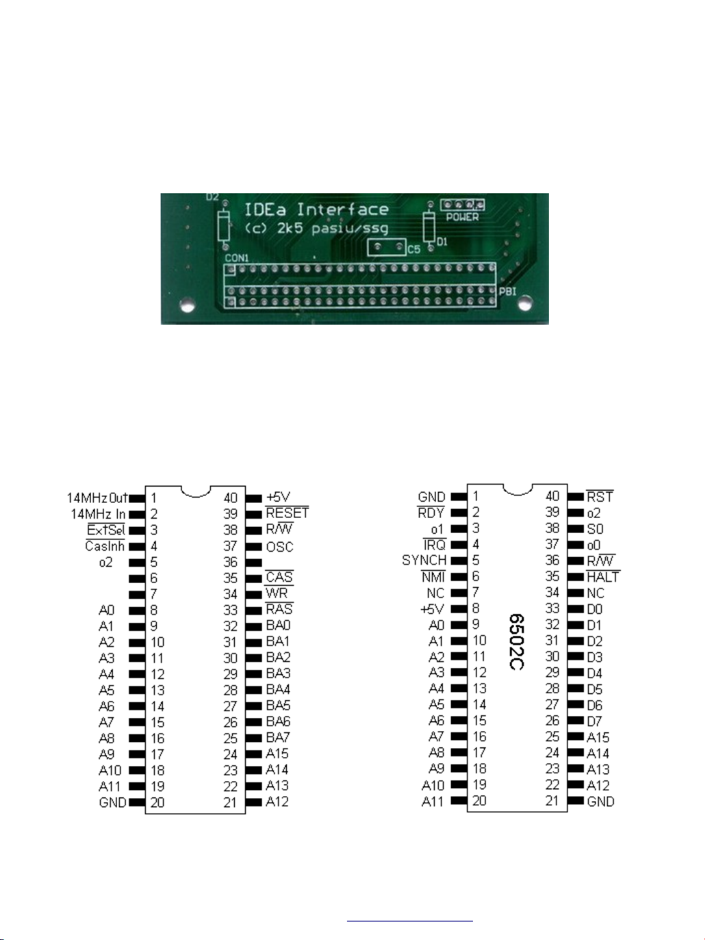
Before you will start take a look at chips pinouts, this will help you find requested signals on them:
Freddie - CO61922 or CO61991 6502C (CPU) - CO14806
- Atari Fan Store
http://afs.atari.org -
Page 2

Antic - CO21698 MMU - CO61618
All connection must be done using as shortest wire as possible:
● pin1 [con1] - GND GND can be connected only one time.
● pin2 - EXTSEL - pin no 3 of Freddie chip. In the case of XEGS or 65XE without EXP port you
have to unsold this pin from motherboard and connect it to VCC through resistor 4.5-10k Ohm)
● pin3 - A0 - pin no 9 of CPU
● pin4 - A1 - pin no 10 of CPU
● pin5 - A2 - pin no 11 of CPU
● pin6 - A3 - pin no 12 of CPU
● pin7 - A4 - pin no 13 of CPU
● pin8 - A5 - pin no 14 of CPU
● pin9 - A6 - pin no 15 of CPU
● pin10 - GND
● pin11 - A7 - pin no 16 of CPU
● pin12 - A8 - pin no 17 of CPU
● pin13 - A9 - pin no 18 of CPU
● pin14 - A10 - pin no 19 of CPU
● pin15 - A11 - pin no 20 of CPU
● pin16 - A12 - pin no 22 of CPU
● pin17 - A13 - pin no 23 of CPU
● pin18 - A14 - pin no 24 of CPU
● pin19 - GND
● pin20 - A15 - pin no 25 of CPU
● pin21 - D0 - pin no 33 of CPU
● pin22 - D1 - pin no 32 of CPU
- Atari Fan Store
http://afs.atari.org -
Page 3

● pin23 - D2 - pin no 31 of CPU
● pin24 - D3 - pin no 30 of CPU
● pin25 - D4 - pin no 29 of CPU
● pin26 - D5 - pin no 28 of CPU
● pin27 - D6 - pin no 27 of CPU
● pin28 - D7 - pin no 26 of CPU
● pin29 - GND
● pin30 - GND
● pin31 - Ø2 - pin no 29 of ANTIC
● pin32 - GND
● pin33 - N/C (not connected)
● pin34 - RST - pin no 36 of ANTIC
● pin35 to pin41 - N/C
● pin42 - GND
● pin43 - MPD - pin no 14 of MMU (in the case of Atari XEGS look below)
● pin44 - N/C
● pin45 - GND
● pin46 - R/W: Read/write direction - pin no 14 of ANTIC
● pin47 - VCC (power supply - e.g. pin no 8 of CPU)
● pin48 - VCC
● pin49 - N/C
● pin50 - GND
*
* If you have Atari XEGS you have to replace original MMU chip with programmed GAL 16V8.
Some tips.
1. If you used too long wire to made your connection you can experience some distortion in
KMKDIAG application
2. Signals A0-A15 and D0 can be find on ANTIC, GTIA and POKEY as well, not only on CPU.
- Atari Fan Store
http://afs.atari.org -
 Loading...