

Page 1
WARNING
• Use of non -Midway parts or circuit modifications may cause serious injury or equipment damage!
• Federal copyright, trademark and patent laws protect this game. Unauthorized modifications may be illegal under
Federal law. The modification ban also applies to Midway Games Incorporated and game logos, designs, publications and assemblies. Moreover, facsimiles of Midway equipment (or any feature thereof) may be illegal under federal law, regardless of whether or not such facsimiles are manufactured with Midway components.
µ
µ
WARNING.
outlet. Do not use a cheater plug to defeat the power cord's grounding pin. Do not cut off the ground pin.
CAUTION.
tary loss of consciousness when viewing certain kinds of flashing lights or patterns that are present in our daily environment. These persons may experience seizures while watching some kinds of television pictures or playing certain
video games. People who h ave not had any prev ious seizures may non etheles s have an un detected ep ileptic conditio n.
If you or anyone in your family has experienced symptoms linked to an epileptic condition (e.g. seizures or loss of
awareness), immediately consult your physician before using any video games.
We recommend that parents observe their ch ild ren while they p l ay v ideo g ames . If you or your child experience the
following symptoms: dizziness, altered vision, eye or muscle twitching, involuntary movements, loss of awareness,
disorientation, or convulsions, DISCONTINUE USE IMME DIATELY and consult your physician.
CAUTION.
improvements in equipment function, design, or components as progress in engineering or manufacturing methods
warrants.
COPYRIGHT & TRADEMARK NOTICE.
mechanical, photographic, or electronic means. You may not produce phonograph recordings of this document. You
may not transmit this publication or otherwise copy it for public or p rivate u se, with out permission from the publisher.
For Service: Call your Authorized Midway Games West Inc. Distributor.
©1998, 1999 Midway Games West Inc. All rights reserved. MIDWAY
Games, LLC. Used by permission. GAUNTLET
Prevent shock hazard and assure proper game operation. Plug this game into a properly grounded
A very small portion of the population has a condition which may cause epileptic seizures or momen-
Information in this manual is subject to change without notice. Midway reserves the right to make
You may not reproduce any part of this publication by
®
is a trademark of Midway Amusement
®
DARK LEGACY™ is a trademark of Midway Games West Inc.
midway games west inc.
675 sycamore drive
milpitas, california 95035
http://www.midway.com
Operations Manua
Setup • Service • Sy
The manufacturer intends that
any federal, state or local law o
operators of this game are resp
turer's factory settings for this g
specific jurisdiction. It is the op
to make the appropriate adjust
675 syca
Page 2

CHAPTER
Setup
NOTICE:
the right to make improvements in equipment function, design, or components as progress in engineering or manufacturing methods may warrant.
Gauntlet: Dark Legacy 3
Information in this manual may c hange without no tice. Midway Games West In c. reserves
Page 3
Chapter 1 Setup
Safety Notices
The following safety instructions apply to all operators and service personnel. Specific warnings and cautions appear throughout this manual. Read this page before preparing your game for play.
CAUTION:
container (P/N 08-8068) in order to be sent in for repair or replacement. Do not stack or drop hard disk
drives during installation or removal.
CAUTION.
rough handling and never move cabinet while power is on.
CAUTION.
voltage. Verify fluorescent lamp is correct for local voltage.
WARNING.
properly grounded. Use only a fixed-location grounded 3-wire outlet. Do not use a "cheater" plug or
cut off ground pin on line cord
WARNING.
internal cabinet AC system and the external AC line.
WARNING.
before removing or repairing any component. After servicing, ensure all ground wires are secure
before restoring power.
NOTICE.
Reversed connectors may damage your machine and void the warranty. Connectors are keyed to fit
specific pins on each board.
The hard disk drive must be packed in an anti-static bag and in an approved shipping
Transport machine securely, as it contains glass and fragile electronic devices. Avoid
Verify switch on the power supply is set for 110VAC or 220VAC according to local line
Avoid electrical shocks. Do not plug in line cord until machine has been inspected and
This video game machine has no isol ation trans former. There is no is olation bet ween the
To avoid electrical shock, turn off power switch and disconnect from AC power source
Ensure proper mating of all connectors. If a connector does not slip on easily , do not force.
WARNING.
current rating of the original fuse.
WARNING.
more from the point of impact. Handle all glass parts carefully.
T o avoid electrical shock, all replacement fus es must match the type, vo ltage rating, and
A dropped fluorescent tube or CRT can break and explode, shattering glass eight feet or
EPILEPSY WARNING
A very small portion of the popula tion has a conditi on which may c ause them to expe rience epilep tic seizures or hav e momentary
loss of consciousness when viewing certain kinds of flashing lights or patterns that are present in our daily environment. These
persons may experience seizures while wa tching some kinds of television pictures or playing certain video games. People who
have not had any previous seizures may nonetheless have an undetected epileptic condition.
If you or anyone in your family has experienced symptoms linked to an epileptic condition (e.g., seizures or loss of awareness),
immediately consult your physician before using an y video games.
Parents should observe their children while they play vi de o g ames. If you or yo u r child e xpe rienc e the follo win g sympt oms: diz ziness, altered vision, eye or muscle twitching, involuntary moveme nts, loss of awareness, disorientation, or convulsio ns,
DISCONTINUE USE IMMEDIA TE LY and consult your physician.
4 Midway Games West Inc.
Page 4

Product specifications
Operating Requirements
Chapter 1 Setup
Electrical Power
Domestic 120VAC @ 60Hz 3.0 Amps
Foreign 230VAC @ 50Hz 2.0 Amps
Japan 100VAC @ 50Hz 3.0 Amps
Cabinet Statistics
Shipping Dimensions
Main Cabinet Control Section
Width 58 in (147 cm) 49 in (124 cm)
Depth 36 in (91 cm) 30 in (76 cm)
Height 79 in (201 cm) 45 in (114 cm)
Equipment Characteristics
Video Display Monitor
Medium resolution RGB
39 in (96.5 cm) CRT
Game Characteristics
Player Variables
1 to 4 players per game
High score recognition
Temperature
32ºF to 100ºF
(0ºC to 38ºC)
Shipping Weight
Main Cab Cntrl Section
580 lbs 140 lbs
264 kg 64 kg
Audio System
Digital Stereo
2 4.5 in (8 cm) full range
speakers
Operator Variables
Coinage, game options,
difficulty, volume, demo
mode, audits, statistics
Humidity
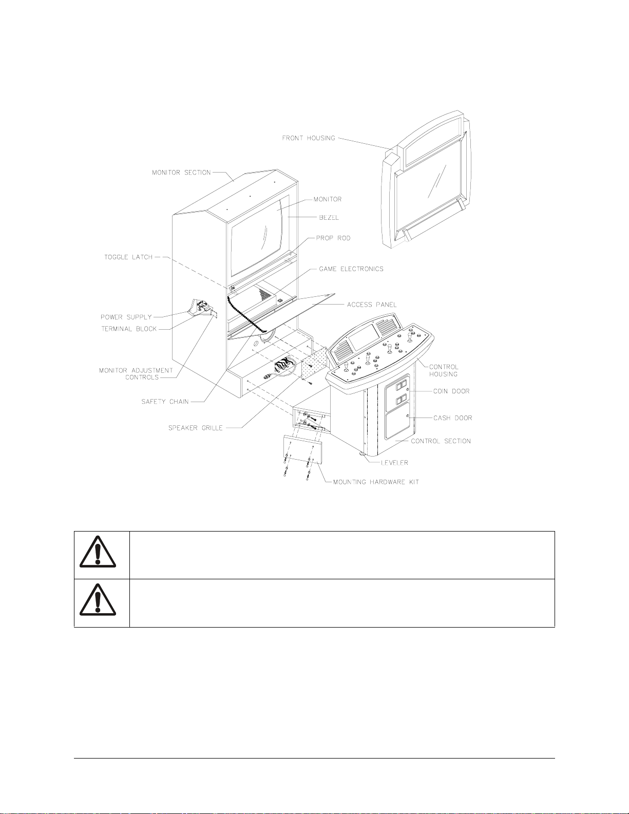
Not to exceed 95% relative
Design Type
Dedicated video game
machine with 49-way
optodetector joysti cks
Currency Acceptors
Standard coin door
2 coin mechanisms
1 coin counter
Diagnostics
Automatic power-up test
Manual multi-level Menu
System
MAINTENANCE
Viewing Glass
You need not switch off AC power to clean the glass. Apply a mild glass cleaner to a clean cloth or
sponge, then use this to wipe the viewi ng glass . Do not appl y cleane r dire ctly on to glas s. Liquid could dr ip
down into video game machine circuits or onto detectors and cause erratic operation.
Cabinet
Use plastic-safe non-a br asi ve cl ea ners to avoid damage. Apply cleaner to cle an cl ot h or sp onge , then u se
this to wipe the controls or cabinet. Do not apply cleaner directly on controls or cabinet.
Gauntlet: Dark Legacy 5
Page 5
Chapter 1 Setup
INSTALLATION AND INSPECTION
1. Remove all components and packaging from shipping containers and set aside.
2. Inspect main cabinet and control section exteriors for damage.
CAUTION.
3. Main cabinet is mounted on four swivel casters. Roll cabinet to intended location, maintaining clear-
ance from walls, drapes, other games or obstructions.
4. Lower each leg leveler unt il cabi net is st able and le vel. Adjust le veler s to rais e wheels up off floor and
distribute weight equally on each corner.
5. Move control section near main cabinet, leaving space to attach wiring harness. Mate each control
cable with its cabinet cable. Press firmly to seat connectors.
6. Lift and move control section against main cabinet, guiding harness into main cabinet.
7. Install and adju st eac h leg l evele r un til c ontro l sect io n is st able a nd leve l. Ad just level ers unt il bot tom s
of both pieces are flush and parallel with each other. Inspect for binding or pinched wires.
8. Locate coin door keys on one of the joysticks. Unlock and open coin door.
9. Locate access panel an d monitor panel keys on rea r fan gri ll. Unl ock and open cash box door. Remove
spare parts stored in cash box.
10. Unl ock and op en fron t door. Let i t rest on su ppor t chai ns. Insp ect cab inet i nteri or for signs o f damage.
Ensure all major assemblies are mounted securely.
Cabinet is top heavy. Do not push against plastic parts during movement
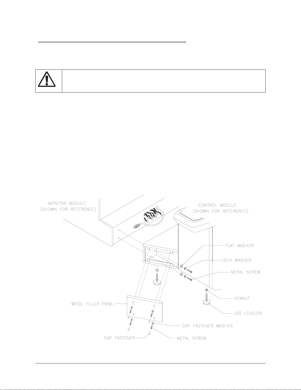
ATTACHMENT OF CONTROL SECTION TO MAIN CABINET
6 Midway Games West Inc.
Page 6

Chapter 1 Setup
11. Refer to Cabinet Wiring Diagram (Wiring Chapter), and ensure all cable connectors are correctly
secured. Do not force connectors, which are keyed to fit in only one location. Bent pins and reversed
connections may damage your game and void the warranty.
12. Pl ace one loc kwasher and one flat wash er onto eac h bolt in spa re part s bag. Align contr ol se ction hol es
with main cabinet holes. Install one bolt with its washers through control section and into each
threaded cabinet hole. Tighten all bolts securely.
13. Place one cover cap washer onto each screw in spare parts bag.
14. Locate wood filler panel inside control section. Reach inside coin door to retrieve.
15. Pl ac e wood fi ller panel over bolt access openi ng in cont rol sec ti on. Ali gn wood filler panel holes with
control section h o le s. Ins ta ll one screw with its wa sher t h r ough wood filler panel and i nto each control
section hole. Repeat installation for remaining wood filler panel, then tighten screws firmly. Snap decorative cover caps over screws.
16. Locate line cord in spare parts. Match holes on IEC plug with prongs in receptacle and push firmly to
seat line cord. Route cord away from cabinet wheels and heavy foot-traffic areas.
LINE CORD INTO POWER SUPPLY
17. Plug game into a grounded (3-terminal) AC wall outlet. Switch AC power on at ON/OFF switch on
center left rear of cabinet. Gauntlet: Dark Legacy powers up and begins self-diagnostics. If no errors
are found, Attract Mode begins.
Gauntlet: Dark Legacy 7
Page 7

Chapter 1 Setup
NOTES
- - - - - - - - - - - - - - - - - - - - - - - - - - - - - - - - - - - - - - - - - - - - - - - - - - - - - - - - - - - - - - - - - - - - - -
- - - - - - - - - - - - - - - - - - - - - - - - - - - - - - - - - - - - - - - - - - - - - - - - - - - - - - - - - - - - - - - - - - - - - -
- - - - - - - - - - - - - - - - - - - - - - - - - - - - - - - - - - - - - - - - - - - - - - - - - - - - - - - - - - - - - - - - - - - - - -
- - - - - - - - - - - - - - - - - - - - - - - - - - - - - - - - - - - - - - - - - - - - - - - - - - - - - - - - - - - - - - - - - - - - - -
- - - - - - - - - - - - - - - - - - - - - - - - - - - - - - - - - - - - - - - - - - - - - - - - - - - - - - - - - - - - - - - - - - - - - -
- - - - - - - - - - - - - - - - - - - - - - - - - - - - - - - - - - - - - - - - - - - - - - - - - - - - - - - - - - - - - - - - - - - - - -
- - - - - - - - - - - - - - - - - - - - - - - - - - - - - - - - - - - - - - - - - - - - - - - - - - - - - - - - - - - - - - - - - - - - - -
- - - - - - - - - - - - - - - - - - - - - - - - - - - - - - - - - - - - - - - - - - - - - - - - - - - - - - - - - - - - - - - - - - - - - -
- - - - - - - - - - - - - - - - - - - - - - - - - - - - - - - - - - - - - - - - - - - - - - - - - - - - - - - - - - - - - - - - - - - - - -
- - - - - - - - - - - - - - - - - - - - - - - - - - - - - - - - - - - - - - - - - - - - - - - - - - - - - - - - - - - - - - - - - - - - - -
- - - - - - - - - - - - - - - - - - - - - - - - - - - - - - - - - - - - - - - - - - - - - - - - - - - - - - - - - - - - - - - - - - - - - -
- - - - - - - - - - - - - - - - - - - - - - - - - - - - - - - - - - - - - - - - - - - - - - - - - - - - - - - - - - - - - - - - - - - - - -
- - - - - - - - - - - - - - - - - - - - - - - - - - - - - - - - - - - - - - - - - - - - - - - - - - - - - - - - - - - - - - - - - - - - - -
- - - - - - - - - - - - - - - - - - - - - - - - - - - - - - - - - - - - - - - - - - - - - - - - - - - - - - - - - - - - - - - - - - - - - -
- - - - - - - - - - - - - - - - - - - - - - - - - - - - - - - - - - - - - - - - - - - - - - - - - - - - - - - - - - - - - - - - - - - - - -
- - - - - - - - - - - - - - - - - - - - - - - - - - - - - - - - - - - - - - - - - - - - - - - - - - - - - - - - - - - - - - - - - - - - - -
- - - - - - - - - - - - - - - - - - - - - - - - - - - - - - - - - - - - - - - - - - - - - - - - - - - - - - - - - - - - - - - - - - - - - -
8 Midway Games West Inc.
Page 8

CHAPTER
Service
NOTICE:
the right to make improvements in equipment function, design, or components as progress in engineering or manufacturing methods may warrant.
Gauntlet: Dark Legacy 9
Information in this manual may c hange without no tice. Midway Games West In c. reserves
Page 9

Chapter 2 Service
Only qualified service personnel should perform maintenance and repairs. The following product guidelines apply to all game operators and service personnel. Specific notes, cautions and warnings appear
throughout this manual. Read safety information in Setup Chapter thoroughly before beginning service.
Control Panel
Switch off AC power. Remove screws along curved front edge of control panel. Protect speaker grilles
where joysticks will touch. Grip joysticks and carefully tilt control panel back on its hinge.
T o r et urn c ontro l pane l to n ormal posi tion, sl owly lean it f orwa rd unt il it r ests on c abinet . Do not let pan el
slam down onto control bas e. Fi x boun d or pi nched wires before re-install ing screws. Rotate each joysti ck
and verify motion is smooth and does not bind.
Coin Mechanism
Switch off AC power. Unlock and open coin door. Unlatch and remove each coin mechanism separately
to clean or replace with a different type. Ensure mechanism seats properly in holder upon reinstallation.
Close and lock release latch, then close door. Turn on AC power and change mechanism setup, then test
known good and bad coins to verify operation.
Dollar Bill Validator
(Use MARS AE2411-U3 or other U.L. Recognized currency changer)
Install dollar bill validators or other currency acceptors in games manufactured with additional wiring
connector. Turn AC power off and unplug line cord. Unlock and open coin door. Read door label for additional information . Remov e nuts , spac ers , and c over p late from do or. Change s witch sett ing or other ad just ments before mounting unit. If manufacturer has supplied an adapter plate, place it over door cutout.
Install spacers on threaded studs, then align validator mounting holes with studs and seat unit in door
opening. Install nuts and tighten firmly. Attach ground wire (green with yellow stripe) lug to door ground
stud next to hinge. Mate wiring harnesses and press to fully seat connectors. Route wires away from door
edges and hinge. Check for proper bill chute alignment. Plug in line cord and turn on AC power. Change
mechanism setup and pricing, then test known good and bad bills to verify proper operation. Close and
lock coin door when correct.
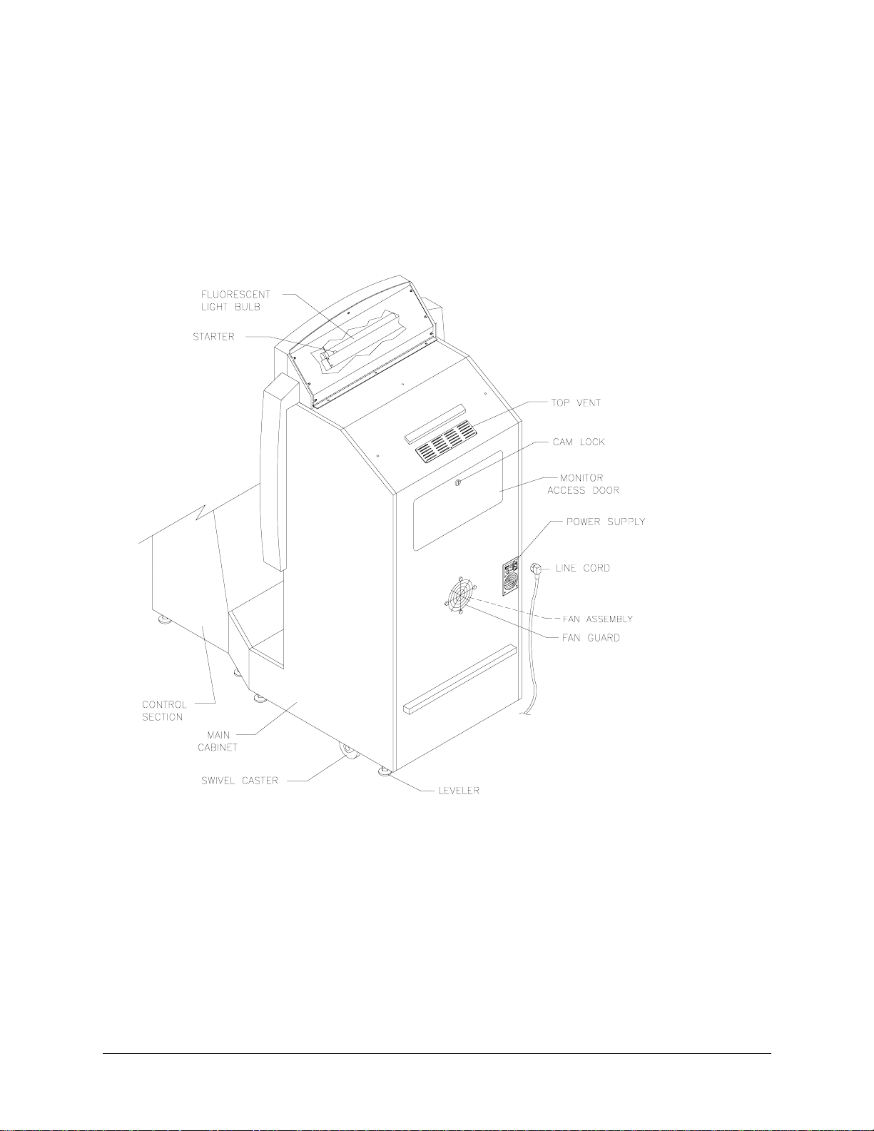
Front Housing/Marquee Assembly
Switch off AC power. Unlock and open front cabinet door until it rests on chains. Unlatch front housing
and gently pull out on bottom, swinging it up towards the control section. Remove free end of prop rod
from retainer at left side of monitor shelf and swing up until it rests in rod bracket on lower right side of
front housing. Disconnect fluorescent light harness. Remove prop rod and snap into retainer before lowering housing to its previous position. Have someone hold housing from control panel side while removing
three screws holding hinge to top of cabinet. Place housing face down on a workbench for service. Do not
overtighten hinge screws during reinstallation.
Viewing Glass
Switch off AC power. Remove front housing and marquee assembly. Set assembly on a workbench.
Remove metal bracket between viewing window and marquee. Remove metal bracket under window. Lift
10 Midway Games West Inc.
Page 10
Chapter 2 Service
viewing glass out of front housing. Clean glass before reinstalling. Install bracket and tighten screws. Do
not use excessive force.
EXTERNAL COMPONENTS
Marquee
Switch off AC power. Open front cabinet door and prop up front housing. Disconnect fluorescent light
harness. Remove Front Housing/Marquee Assembly and place on a workbench. Remove metal bracket
between viewing window and marquee. Remove metal bracket at top of marquee opening. Lift glass and
artwork out from front housing. Clean glass before reinstalling. Tighten screws.
Fluorescent Light Assembly
WARNING.
Switch off AC power. To change starter or b ulb, open front cabinet door and prop up front hous ing. Grasp
bulb at each end and give it a quarter turn. Gently pull bulb straight out to remove from sockets. Starter
Gauntlet: Dark Legacy 11
If a dropped fluorescent tube or a CRT breaks, it will implode. Use care in handling.
Page 11

Chapter 2 Service
also requires quarter turn for removal. Do not force bulb or starter during reinstallation. Clean bulb to
remove fingerprints a nd dust. Cl ose hous ing and t urn on AC powe r. Verify lamp lights before locking door.
To remove entire light fixture, open door and prop up housing. Disconnect fluorescent light assembly
connector from power cable. Close and remove housing from cabinet, setting it on a workbench. Remove
bulb. Remove screws that hold assembly to light cover, then lift out assembly. Ballast is in the base.
Instruction Overlay and Mini Marquee
Remove eight screws from speaker panel. Lift cover up and off to expose instruction overlay and mini
marquee. Bulbs may be removed from strip light assembly with a fuse puller when necessary.
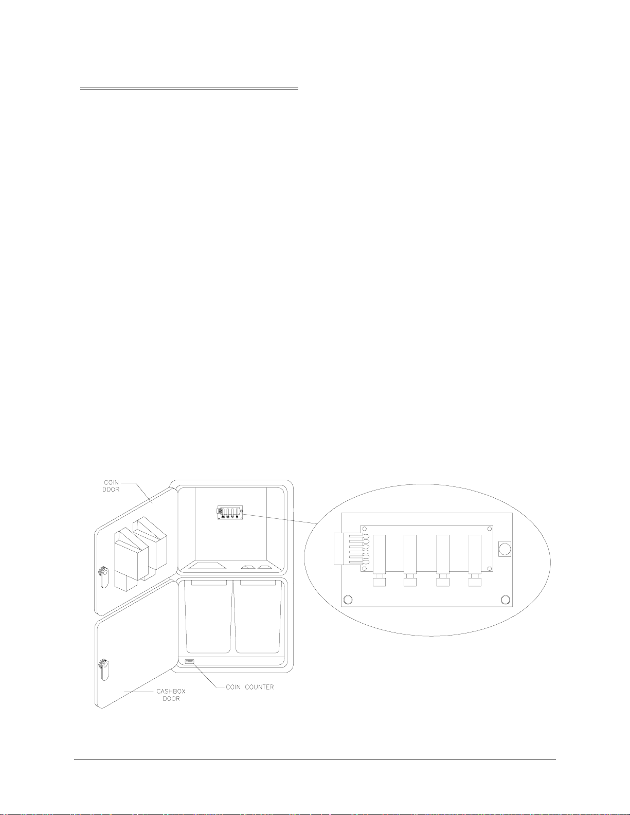
Coin Counter
Switch off AC power. Unlock and open coin and cash doors. Meter is in a lower corner of the door opening. Record meter count before testing or replacing.
Disconnect wiring harnesses and ground wires to coin mechanisms. Reach through coin door and locate
meter wires. Disconnect wires. Remove coin door mounting screws. Remove coin door and set on a workbench. Remove meter mounting screws from front. Ensure replacement unit has a diode across the terminals. Remember to reconnect wiring harnesses and ground wire upon reinstallation.
Joysticks
Switch off AC power. Protect speaker gr illes an d open contro l panel. Mark an d discon nect wiring har ness
at joystick. Remove fasteners and separate joystick from panel. Remove E-ring and stop spacer from end
of joystick shaft, then grasp knob and extract stick from the assembly. Remove corner screws to free slide
carriage and stop piece from joystick top. This exposes centering grommet. Do not cross-thread screws
during reassembly.
Speakers
Switch off AC power. Two full range speakers are mounted behind grille at top of the control section.
Grill and speakers come out th e front. Remove sc rews and set gr ille asi de. Always remove upper mounting
screws first and replace them last to avoid damaging speaker.
Remove speakers from enclosure and disconnect wires. Refer to Cabinet Wiring Diagram for speaker
wiring information. Do not use excess force when removing or tightening mounting screws threaded into
plastic.
Monitor
Switch off AC power. Open front cabinet door . Move moni tor r emote b oard an d wiri ng harn ess an d place
it in monitor assembly. (Monitor remote adjustment board is behind front door.) Disconnect fluorescent
light assembly connector and all monitor cables. Remove front housing hinge screws and set housing
aside. Remove monitor bezel and all barrier panels. Remove four flange nuts securing monitor mounting
12 Midway Games West Inc.
Page 12
Chapter 2 Service
brackets to mounting panel. Pull monitor carefully from cabinet and set in safe place. Clean CRT face
before rein stalling barrier panels and monitor bezel.
INTERNAL COMPONENTS
CAUTION.
itor when you remove it from cabinet.
WARNING.
when operating outside the cabinet or servicing the monitor on a test bench, you must isolate monitor
from line voltage with an isolation transformer
Vid eo moni tor is heavy , with most we ight t oward front of assembly. Firmly support mon-
Monitor does not require isolation from AC line voltage in normal operation. However,
Buttons
Open control panel. Mark and disconnect wiring harness at the switches. Bend large prong away from
each switch just enough to slide switch off housing. Separate each switch from its button. Mark switches
and harnesses with player numbers and lay them inside control panel box. Unscrew mounting nut from
housing. Remove button housing through switch hole from front of control panel.
Gauntlet: Dark Legacy 13
Page 13
Chapter 2 Service
CPU Board Assembly
Switch off AC power . Open fr ont door . Remove gr oundplane cover to expose Electroni cs Assembly. Note
orientation of JAMMA connector and other cables. Extract harness and hard disk drive ribbon cable from
board connectors. Remove gr ound pla ne moun ting s crews. Sl ide ent ire e lectroni cs ass embly out of cabi net
and set in static-free place. Disconnect VGA connector. Remove mounting screws from circuit boards.
Carefully remove Sound I/O Boa rd, pull ing gentl y to discon nect P CI e dge con nector from CPU Board. Set
Sound I/O board in static-free place. Carefully remove CPU Board, pulling gently to disconnect from
Video Card. Use anti-static bags and protective containers from new parts to store board, if not reinstalled.
REAR VIEW OF CABINET
Sound I/O Assembly
Switch off AC power. Open front door. If used, remove metal cover top to expose Electronics Assembly.
Carefully note orientation of JAMMA connector and other cables. Extract harness and hard disk drive ribbon cable from board connectors. Remove groundplane mounting screws. Slide entire electronics assembly from cabinet and set in a static-free place. Remove mounting screws from circuit board. Carefully
remove Sound I/O Board, pulling gently to disconnect PCI edge connector from CPU Board. Use anti-
static bags and protective containers from new parts to store board if not reinstalled.
14 Midway Games West Inc.
Page 14
Chapter 2 Service
Hard Disk Drive
Switch off AC power. Unlock and open front cabinet door until it rests on chains. Remove metal cover
from electronics assembly. Disconnect power cable from hard disk drive. Unplug ribbon cable from hard
drive and leave attac hed to CPU board. Remove screws and lif t d ri ve a sse mbly f r om c abi ne t. Do no t stack
or drop drives. Store drives in anti-static bags or approved shipping containers.
CAUTION.
drop hard disk drives. Store unused hard disk drives in anti-static bags.
Hard disk drives are fragile. Never move cabinet while AC power is on. Never stack or
Video Card
Switch off AC power. Open front door. If used, remove metal cover top to expose Electronics Assembly.
Disconnect VGA connector. Remove screws holding Video Card to groundplane. Carefully slide Video
Card away from CPU Board, disconnecting PCI edge connector. Use anti-static bags and protective containers fro m new parts to store board i f not reinstalled.
Memory
ROM (Read Only Memor y) circuits contain computer operating instructions. Switch off AC power. Carefully note position, then remove using chip extraction tool.
To reinstall memory circuits, orient chip over its socket and press firmly to seat pins. Do not force.
Power Supply
Switch off AC power and disconnec t li ne cor d. Unlo ck and ope n fron t door. Unplug IEC connector from
top of supply and wiring har nes ses from back. Disconnect DC. power cabl e f ro m har d di sk dr ive. Remove
two rear screws from supply, then slide from cabinet. Verify line voltage switch setting before reinstalling
power supply.
CAUTION.
Do this before touching or handling electronic assemblies.
Discharge any static electricity built up in your body by touching power supply chassis.
Battery
Switch off AC power. Unlock and remove rear door. Remove perforated metal cover. Battery is mounted
on top of integrated circuit at Sound I/O Board Assembly location U28. Use chip extraction tool to grasp
battery edges and pull up firmly to remove device. Set aside with pins facing up. When installing new battery, align key with slot in integrated circuit.
NOTE.
composition. These batteries are designed for very long life. Do not attempt to recharge. Avoid direct
shorts across terminals or from terminals to ground. Remove from their holders and store in a safe
place until repairs are complete. Dispose of used batteries according to manufacturer's instructions
Gauntlet: Dark Legacy 15
To avoid explosion, replacement batteries must match original in size, voltage rating, and
Page 15

Chapter 2 Service
NOTES
- - - - - - - - - - - - - - - - - - - - - - - - - - - - - - - - - - - - - - - - - - - - - - - - - - - - - - - - - - - - - - - - - - - - - - -
- - - - - - - - - - - - - - - - - - - - - - - - - - - - - - - - - - - - - - - - - - - - - - - - - - - - - - - - - - - - - - - - - - - - - - -
- - - - - - - - - - - - - - - - - - - - - - - - - - - - - - - - - - - - - - - - - - - - - - - - - - - - - - - - - - - - - - - - - - - - - - -
- - - - - - - - - - - - - - - - - - - - - - - - - - - - - - - - - - - - - - - - - - - - - - - - - - - - - - - - - - - - - - - - - - - - - - -
- - - - - - - - - - - - - - - - - - - - - - - - - - - - - - - - - - - - - - - - - - - - - - - - - - - - - - - - - - - - - - - - - - - - - - -
- - - - - - - - - - - - - - - - - - - - - - - - - - - - - - - - - - - - - - - - - - - - - - - - - - - - - - - - - - - - - - - - - - - - - - -
- - - - - - - - - - - - - - - - - - - - - - - - - - - - - - - - - - - - - - - - - - - - - - - - - - - - - - - - - - - - - - - - - - - - - - -
- - - - - - - - - - - - - - - - - - - - - - - - - - - - - - - - - - - - - - - - - - - - - - - - - - - - - - - - - - - - - - - - - - - - - - -
- - - - - - - - - - - - - - - - - - - - - - - - - - - - - - - - - - - - - - - - - - - - - - - - - - - - - - - - - - - - - - - - - - - - - - -
- - - - - - - - - - - - - - - - - - - - - - - - - - - - - - - - - - - - - - - - - - - - - - - - - - - - - - - - - - - - - - - - - - - - - - -
- - - - - - - - - - - - - - - - - - - - - - - - - - - - - - - - - - - - - - - - - - - - - - - - - - - - - - - - - - - - - - - - - - - - - - -
- - - - - - - - - - - - - - - - - - - - - - - - - - - - - - - - - - - - - - - - - - - - - - - - - - - - - - - - - - - - - - - - - - - - - - -
- - - - - - - - - - - - - - - - - - - - - - - - - - - - - - - - - - - - - - - - - - - - - - - - - - - - - - - - - - - - - - - - - - - - - - -
- - - - - - - - - - - - - - - - - - - - - - - - - - - - - - - - - - - - - - - - - - - - - - - - - - - - - - - - - - - - - - - - - - - - - - -
- - - - - - - - - - - - - - - - - - - - - - - - - - - - - - - - - - - - - - - - - - - - - - - - - - - - - - - - - - - - - - - - - - - - - - -
- - - - - - - - - - - - - - - - - - - - - - - - - - - - - - - - - - - - - - - - - - - - - - - - - - - - - - - - - - - - - - - - - - - - - - -
16 Midway Games West Inc.
Page 16
CHAPTER
System
NOTICE:
the right to make impro vements in equip ment funct ion, des ign, or componen ts as progr ess in engineering or manufacturing methods may warrant.
Gauntlet: Dark Legacy 17
Information in this manual may change without notice. Midway Games West Inc. reserves
Page 17

Chapter 3 System
STARTING UP
Each time the game is f ir st tu rned on or power is restor ed, it beg ins executing code out of the boo t ROM.
These self-diagnostic tests automatically verify and report condition of the hardware and the disk drive.
The screen is blank durin g these tests. If any of the individual tests fails, the n an error message will be di splayed for each test. The message will be displayed for 30 seconds or until any button is pressed.
• If no buttons are pressed, the system will quickly complete all tests then load and run the game.
• Press and hold the TEST button inside the coin door to skip the boot ROM tests and activate the Menu System.
Once all Power-up tests have been passed, the game goes into Attract Mode. Scenes and sounds from a
typical game are alternated with previous high scores in an endless pattern until game play starts.
Insert currency to start game. Play begins after a mission is chosen. The game progresses until time runs
out. If no more play is requ ired, the game automatica lly returns to the "attract mode".
GAME RULES
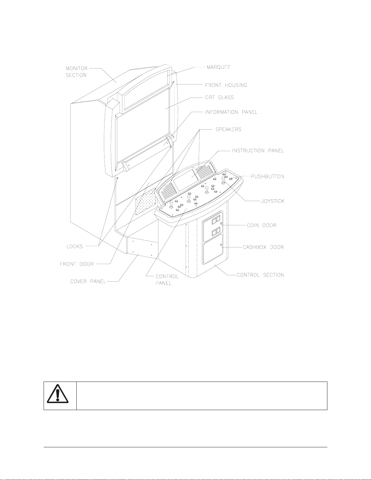
Play instructions are on information panel between speakers. Up to four players at a time can explore a
world, facing hordes of monsters, searching for treasure, avoiding traps, finding and using magic, and
adventuring their way to the exits.
Players choose from eight charact ers (a nd, lat er, eight alternat e chara cter s) to fa ce the hor des o f monsters
that have overrun the land of Gauntle t. With more than 100 uni que monst ers a nd 10 int imidat ing bos s char acters, players have their hands full, defeating each of the eight world bosses and collecting keys before
meeting the demon Skorne. Fol lowing Skor ne’s defeat, player s must defea t him yet ag ain in an un derworld
level, after which they face the evil overlord Garm. Numerous power-up enhan cements are scattered
throughout the land to help players get to the finish.
Players can save their character with player IDs. One password saves all eight different characters. During game variable selection, players simply enter their initials and their own 3-letter player ID that they
choose. The charact er s, wi th the ir exp eri ence levels and current ra ti ngs for strength, speed, t ough nes s, and
magic are automatically saved along with any Rune Stones players find.
To access the alternate characters, players first build characters to level 10. Depending upon which character they have played, they then can choose to play as the Minotaur (Warrior), Falconess (Valkyrie),
Jackal (Wizard), Tigress (Archer), Hyena (Jester), Ogre (Dwarf), Medussa (Sorceress), and Unicorn
(Knight).
To defeat Garm, players must find all 13 Rune Stones and defeat Skorne twice. Three Stones are hidden
in each world. Upon finding a Stone, a character is saved permanently with a password.
There are over 35 unique spec ial weap ons found through out the game th at will hel p players i n their ques t.
These power-ups are found in chests and barrel s, in nooks and crannies, an d even in plain view and can b e
bought with gold in the Shop.
18 Midway Games West Inc.
Page 18
Chapter 3 System
INDIVIDUAL AND MULTIPLE PLAY
Insert currency to start game. Select a joystick/button co mbination a nd press START. Select a password ,
character, and journey. In multi-player games the first to select a journey determines everyone’s path. Onscreen life counters decrease as characters are wounded until they reach zero, at which point the player
must deposit more coins to continue. You can continue playing after others drop out. When coins are
inserted, the character joins in the mi ddle of the ac tion.
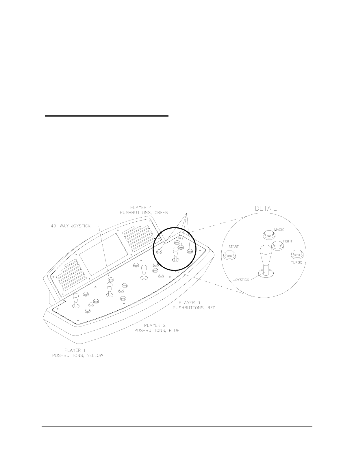
PLAYER CONTROLS
START buttons let players begin or continue play and also select items from the service menu.
FIGHT/MAGIC/TURBO Buttons attach enemies. Players access special turbo movies by pressing
TURBO and FIGHT at the same time when their "fight bar" has been charged up.
Magic is used by pressing TURBO + MAGIC and FIGHT + MAGIC during game play.
Between levels, players redeem accumulated gold for valuable power-ups and things that will enhance
their characters like str eng th, tou ghness, speed, and magic.
JOYSTICKS advance a character along a journey and select items from service menu.
PLAYER CONTROL LOCATIONS
Gauntlet: Dark Legacy 19
Page 19
Chapter 3 System
OPERATOR CONTROLS
Operators have lock-and-key access to the menu system for statistics, adjustments, and testing to prevent
tampering. On-screen messages guide the operator through menu options.
Cabinet Switches
The Power Switch (located on the power supply at the rear of the cabinet) turns off the game during service. It does not reset the game variables.
Monitor Remote Adjustments
The Monitor Remote Adj ustment Board (locat ed just behin d the coin do or) set s the video displ ay for opti mum viewing.
Control Switches
Volume Down and Volume Up But to ns ( m ount ed on a bracket behind the c oin door) increase or de cre ase
game sound levels.
NOTE Attract Mode volume is set as a percentage of Game Mode volume. When volume up/down buttons are pressed during Attract mode the volume is temporary set to game volume.
For greater profits, adjust volume levels to a loud setting to draw attention to this game.
T est Mode Button The Test Mode push-button switch enters the menu syst em. Press the Test Mode button
briefly to run automatic tests. To make changes, press and hold Test until the system menu is displayed.
Service Credit Button: this button allots credits without changing the game's bookkeeping total.
These buttons may also be used instead of the control panel buttons and joystick when operating the
menu system.
SERVICE VOL. VOL. TEST
CREDIT DOWN UP
TEST SWITCH BRACKET
MODE
OPERATOR CONTROLS
20 Midway Games West Inc.
Page 20

Chapter 3 System
MENU SYSTEM
SYSTEM OVERVIEW
Game variables and diag nosti cs are prese nted i n a ser ies o f on-s creen menus . The Main Menu al lows yo u
to view informat ion, change or verify equipment operation. Submen us display further choices, after which
more data appears or tests run. Use both operator and player controls to navigate menus and start or stop
routines.
SCREEN LAYOUT
The color bar at the top center of each screen displays the current menu title. The center of the screen
holds data (menu items, video signals, statistics, reports, etc.) The bottom of the screen contains messages
(control functions, revision levels, etc.).
ORGANIZATION
Main Menu screen items are either options or tests. Submenu screen items offer choices within a category. A Menu may have zero, one, or several Submenus . You can always return to the previous menu, and
often advance to the next menu. Detail Menu screen items contain specific information. You interact with
the system to get results or to make changes.
Use the indicated control to highlight an item. You can only select one highlighted at a time. To return to
game play, select EXIT TO GAME, then press the indicated button.
SELECT TEST
DATE TIME
ADJUST VOLUME
STATISTICS
GAME OPTIONS
COIN OPTIONS
DIP SWITCHES
CONTROLS TEST
SOUND TESTS
MONITOR TESTS
DISK TESTS
SET RTC
EXIT TO GAME
To select test, Use Joystick.
To run test, Press right P1 START or TEST
EPROM: (Day Date Year) (Hours: Minutes: Seconds)
GUTS: (Day Date Year) (Hours: Minutes: Seconds)
MAIN: (Day Date Year) (Hours: Minutes: Seconds)
SERIAL NO:
TYPICAL SELECT TEST MENU SCREEN
Gauntlet: Dark Legacy 21
Page 21

Chapter 3 System
ADJUST VOLUME
You can adjust Attract Mode volume independently of Game volume. Use the joystick to raise or lower
volume level. Music plays continuously while setting volume.
ADJUST VOLUME
GAME
************ ************* ********** ********** ************ ***********
************ ************* ********** ********** ************ ***********
************ ************* ********** ********** ************ ***********
Attract (XX% of Game)
************ ************* ********** ********** ************ ***********
************ ************* ********** ********** ************ ***********
************ ************* ********** ********** ************ ***********
to Select which volume, Press P1 START or TEST
to RESTORE old setting, Press and hold P1 START or TEST
to SAVE setting and exit, Press P2 START or CREDIT
To ADJUST volume, Use Joystick
VOLUME ADJUSTMENT MENU SCREEN
Use the Player 1 START button to choose Game or Attract volume adjustment. When the selected variable flashes, use the joystick to change the level.
Game volume adjusts from zero to maximum. The game seems more realistic if players experience loud
sounds during play. These weapons do not have silencers.
Attract volume is continuously adjustable from Mute (zero) to maximum. For greater profits, make
Attract Mode loud to draw attention to Gauntlet: Dark Legacy.
You adjust Attract and Game volume levels independently, but Attract cannot be louder than Game volume. If you try this, Attract level automatically lowers proportionately. Lowering Attract level does not
affect Game sett in g.
Volume level is represented a bar made of dots. The longer the bar, the higher the volume.
Press the Player 2 START button after making volume adjustments. The Player 1 START button cancels
your recent changes and returns both levels to what they were before you touched them.
NOTE: These adjustments affect both the volume of the tests and game play. If the volume levels are set
to minimum (zero), ther e will be no s ounds f rom the spe akers during any of the audio tests . Set t he vol ume
levels to a mod er ate ly hi gh value when checking the game audio compon ent s and speakers. Return th e l ev els to their previous settings after completing the tests.
22 Midway Games West Inc.
Page 22

Chapter 3 System
STATISTICS
The Statistics report allows the operator to asses s how well the game is being played. In addition to the
earnings, various game aspects are tracked to determine the player skill levels.
Statistics may be reset to zero or allo wed to incre ase after each viewing.
STATISTICS
Left Coins :0
Right Coins :0
Service Credits :0
1 Credit Games :0
2+ Credit Games :0
Idle Mins :0
1 Player Mins :0
2 Player Mins :0
3 Player Mins :0
4 Player Mins :0
Number of Sessions :0
Number of Join-Ins :0
Total Game Starts :0
Total Coins :0
Average Time/Coin :0
Percentage Play :0
Hold P1 START or TEST and press P2 START
For more stats, Press P2 START or CREDIT
To clear these counters,
STATISTICS REPORT MENU SCREEN
The illustration shows how the re port scr een looks after the game is rese t or is fir st turn ed on. Most stat istics increase in value as the game is played. It is normal for some values to remain at zero: for example, the
Aux Coins count will not change unless an additional Currency Acceptor has been installed in the game,
and the Error Count will not change if no errors have occurred.
Low counts in both coin and player statistics may suggest the game is too difficult for the skill levels of
the players at this location; high continue counts may indicate the game is too easy. Difficulty level and
other play characteristics may be adjusted from the Game Options menu.
Record statistics before performing service or making repairs on the game.
Press Player 2 START or service credi t butto n to view s ystem er rors, whi ch tel l you the status of t he hard ware. Press Player 2 START again, and you will see user messages. Press Player 2 START again and you
will see histograms. Press Player 2 START again to see level histograms.
Press both START buttons to cancel settings on screen and return all counts to factory default values.
The HISTOGRAMS screens will have no bar graphs until the system has enough data to plot.
The USER MSGS screen will contain no messages until the system detects an error.
Gauntlet: Dark Legacy 23
Page 23

Chapter 3 System
GAME OPTIONS
These adjustments allow you to customize the game. Each variable changes an aspect of game appearance or play. Optimum settings cause high player interest and increase earnings.
Use the joystick to select a menu item and to view the range of choices or change their value. Options
may be reset to factory defaults or changed after each viewing.
Difficulty:
Health Per Credit:
Blood:
Freeplay Demo Mode:
Health Decrease Timer:
Text In:
Reduce Hints:
Audio Mode:
Audio in Attract:
Cabinet Type:
Contest Enabled:
Codes Enabled:
Allow Password:
Clear Password Files:
Auto Clear Highscores:
Restore Factory Game Options:
5 Medium
500
Yes
No
Normal
English
No
Stereo
Often
4 Players 1 Cabinet
Yes
Yes
Yes
No
Yes
No
To RESTORE old setting, press P1 START or TEST
To SAVE setting and exit, press P2 START or CREDIT
To change settings use Joystick
GAME OPTIONS
GAME OPTIONS MENU SCREEN
Factory defaults are displayed in green text.
The illustration shows how this report screen looks after game is reset or first turned on. Use joystick to
advance variables through range of choices. Some items have more options than others. View all options
before selecting one.
The effects of these options can be judged by comparing statistics reports before and after changes were
made. As players become more familiar with the game, new features or increased difficulty will make the
game challenging and continue to generate interest.
Difficulty adjusts the level of play difficulty. It ranges from easiest to hardest in several steps. Default is
Medium.
Health Per Credit determines amount of health cred its added to the timer each t i me a player uses a credit
by pressing the START button. It ranges from 300 to 1000. Factory default is 500.
Blood controls whether blood and gore appear on screen when a character is killed. Factory default is
Yes.
24 Midway Games West Inc.
Page 24

Chapter 3 System
Freeplay Demo Mode increases the maximum number of health credits allowed on the health timer per
game credit beyond normal game limits. Factory default is Off.
Health Decrease Timer sets the speed of the Healt h ti mer. It ran ges from Off to Fast in several steps. Fac tory default is Normal.
T ext s In select s the lan guage of t he on-scr een anno unce ments and hi nts. Sel ectio n of a dif fe rent l angu age
changes the player in forma tion prese nted on ly on the scr een. It does not change a ny of th e voice a nnounce ments, menu screens or tests. Factory default is English.
Reduce Hints sets the frequency of visual and verbal assistance to a player during the game. Yes
decreases the frequency of hints. Factory default is No.
Audio Mode sets the audio output of the game. Use Stereo for cabinets with more than one speaker. Use
Mono for cabinets with a single speaker. Factory default is Stereo.
Audio in Attract sets the frequency of game play instructions whil e t h e game is idle and in Attract Mode.
It ranges from Never to Always. Factory default is Often.
Cabinet Type configur es the number a nd type of inputs for t he cabi net. Fa ctory def ault is 4 Playe rs 1 Cab inet. Factory default is 4 players 1 cabinet.
Allow Password controls whether the game will save a player's character experience with a three-digit
password for later games. Factory default is Yes. Take special caution before changing this setting, as
many registered players invest much time and money into building up their characters, which can only be
accessed with passwords.
Contest Enabled allo ws Midway spons ored T-s hir t promot ion. Play ers who def eat Gar m by coll ecti ng all
13 rune stones and winning the final battle are eligible for an "I Beat Garm" T-shirt. Factory default is Yes.
Codes Enabled allows use of secret codes. Factory default is Yes
Clear Passw ord files controls password file deletion . Set this featu re to Yes to delete al l saved character
experience and passwords. Factory default is No.
Auto Clear Highscores sets whether the game will automatica lly reset the high score table from time to
time. Factory default is No.
Restore Factory Game O ptions resets the Game Opti ons. Set this option to Yes to reset the game to fa ctory default options. Factory default is No.
Record the High Scores before making any option changes to the game.
NOTE: Changes to Game Diff icult y or Numbe r of li ves au tomati cally reset the Pl ayer Hi gh Score s, sinc e
these varia bles directly aff ect the ability to collect po ints .
Gauntlet: Dark Legacy 25
Page 25

Chapter 3 System
COIN OPTIONS
PRICING OPTIONS
Use the Player 1 joystick to select menu items, view the range of choices, and change values. Options
may be reset to factory defaults or changed after each viewing.
PRICING OPTIONS
Free Play:
Start Game Cost:
Continue Game Cost:
Bonus for quantity buy-in:
No
2 Coins
2 Coins
None
To RESTORE old Setting, Press P1 START or TEST
To Save setting and exit, Press P2 START or CREDIT
To change setting, use Joystick
PRICING OPTIONS MENU SCREEN
Custom pricing sets credits required to start and continue a game, rewards for buy-in and winning, etc.
Factory default are shown above. View all choices before se lecting, as some items have more opt ion s than
others. Free offers no options. Free game incentives may reduce earnings.
26 Midway Games West Inc.
Page 26

Chapter 3 System
COIN OPTIONS
PRICING OPTIONS
Mech setup permits o perators to add or remove c oin or bi ll mechani sms. Values are shown for all devi ces,
but changes to unused inputs have no effect if the mechanism is not in the game.
MECH SETUP
Activate mech to test. Current status:
Each Mech 1 pulse worth:
Each Mech 2 pulse worth:
Each Mech 3 pulse worth:
Each Mech 4 pulse worth:
Each Bill pulse worth:
Stats and Counters count:
Mech 1 Mech 2 Mech 3 Mech 4 BILL Service
1 Coin
1 Coin
1 Coin
1 Coin
1 Coin
Coins
To RESTORE old Setting, Press P1 START or TEST
To Save setting and exit, Press P2 START or CREDIT
To change setting, use Joystick
MECH SETUP MENU SCREEN
DIP SWITCHES
The two DIP switches located at U13 and U12 on the SIO Board configure the Electronics Assembly for
various input and output devices. The on screen display shows the switch status for easy reference. See
Wiring Chapter for specific information on the function of switch positions.
U13
----1OFF
2 OFF Run Game
3 OFFNot Used
4 OFFNot Used
5 OFFNot Used
6 OFFNot Used
7 OFFNot Used
8 OFFNot Used
U12
----1ON
2 OFF Medium Resolution (512 x 384)
3 ON49-Way Joysticks
4 ONMidw ay Cabinet/Harness
5 OFF SIO rev 1 or greater
6 OFFNot Used
7 OFFNot Used
8 OFFNot Used
To return to Menu, Press P2 START or CREDIT
DIP SWITCHES
DIP SWITCH MENU SCREEN
Gauntlet: Dark Legacy 27
Page 27

Chapter 3 System
CONTROLS TEST
These tests allow the operator to manually check each switch in the game.
NOTE.
Some switches may not be used in Gauntlet: Dark Legacy. Check wiring diagram before test-
ing.
Use the joystick to select the Controls Test. Press Player 1 START button to begin test. Activate each
switch and the indication on the screen changes state. Release the switch and the indicator returns to its
previous normally open or closed condition. Test switches in any combination.
CONTROLS TEST
COIN MECHS
------------------1 2 3 4
SVC BILL
Plyr 1 Plyr 2 Plyr 3 Plyr 4 MISC
-------- -------- -------- -------- --------
• • • • • • • • • • • •
• • • 0 0 • • • 0 0 • • • 0 0 • • • 0 0
• • • • • • • • • • • •
START START START START VOL+
MAGIC MAGIC MAGIC MAGIC VOLFIGHT FIGHT FIGHT FIGHT TEST
RUN RUN RUN RUN ITRLK
TILT
GRN=Switch ok, RED=Switch ON, YEL=Switch not tested.
Press TILT switch to activate coin counter
Press and hold P2 START or CREDIT to return to menu
CONTROLS TEST MENU SCREEN
Each switch change s hou ld be exactly duplicated by a single indicati on o n the menu screen. The alphanumeric indi cators next to each joystick should display three distinct settings as the stick is moved in each
direction toward its outermost limit.
Player Controls Tests verify crossed wires, intermittent conditions, and stuck switches.
OPERATOR CONTROLS are shown on screen under the MISC heading. Each switch change should be
exactly duplicated by a single indication on the menu screen.
Operator Controls Tests verify crossed wires, intermittent conditions, and stuck switches.
Coin and Cabinet Switches are shown on the screen without regard for their actual game location. Each
switch change should be exactly duplicated by a single indication on the menu screen.
28 Midway Games West Inc.
Page 28

Chapter 3 System
SOUND TESTS
These tests veri fy th e proper connection and operation of the audio co mp onen ts . The re are no custom settings or variables in these tests, wh ich are performed automatically.
SPEAKER TEST
LEFT RIGHT
To Return to Menu, Press P2 START or CREDIT
SPEAKER TEST
MENU SCREEN
SPEAKER TEST sends alternating voic e sounds to the left and rig ht speaker s. Voices should be clear and
distinct from each other. Each voice must come from the location identified. Refer to ADJUST VOLUME
screen if necessary to increase loudness for this test.
The Speaker Test screen verifies crossed connections, incorrect phase, and distortion. Press the Player 2
START button to end the Audio Speaker Test and return to the SOUND TESTS menu.
AUDIO HARDWARE TEST
Hardware Reset: PASSED
I/O Port Test: PASSED
EPROM Revision: XX.X
SDRC Revision: XX
PM Checsum: XXXX
S/RAM Test: PASSED
D/RAM 0 Test: PASSED
EPROM Bong Test : PASSED
Software Reset: PASSED
Sound FIFO Test: PASSED
DCS2 OS Version: XX.XX
To Return to Menu, Press P2 START or CREDIT
AUDIO HARDWARE TEST REPORT SCREEN
AUDIO HARDWARE TEST automatically tests the electronic components of the audio amplifier for
problems and reports the results as "passed" or "failed." Each "failed" result should be noted and referred
to qualified service personnel. This test also shows the revision numbers for the audio EPROMs and other
components. Press SERVICE CREDIT to return to the SOUND refer to the Troubleshooting Chapter.
Gauntlet: Dark Legacy 29
Page 29

Chapter 3 System
MONITOR TESTS
Monitor Tests provide patterns to verify monitor performance or make adjustments. Gauntlet: Dark Legacy uses a medium-resolution monitor. Other monitors may cause poor performance.
Use the joystick t o select a menu item. Press t he Player 1 START button to begin the test. Once the menu
is open, use the joystick to select an option, and the Player 1 START button to begin it. Use the Player 1
START button to select various elements of each test. Press the Player 2 START button to return to the
Monitor Tests menu screen.
MONITOR TESTS
COLOR BARS
CONVERGENCE
PURITY
To select test, Use joystick
To run test, press P1 START or TEST
To return to menu, press P2 START or CREDIT
MONITOR TESTS MENU SCREEN
COLOR BARS fills the screen with shades of colors to verify red, green, blue and white level dynamic
adjustments. Each bar should appear sharp, clear, and distinct from bars on either side.
Borders must be visible on top, bottom, and sides of screen. Bars should not change screen position or
color as the background or border are removed or restored from the video display.
Color Bars screen is useful in adjusting the monitor brightness and contrast.
CONVERGENCE tests fill the s cr een wi th a grid and a seri es of dots. Grid and the dots should be all one
color, with no fringes or parallel images. Lines should be straight and dots round.
Borders must be visible on top, botto m, and sides of sc reen. Line s and dots shou ld not chang e positi on or
color as background or border are removed or restored from video display.
Convergence tests are useful in verifying the monitor convergence, linearity, and dynamic focus.
PURITY tests fill the screen with 100% of the chosen color at normal intensity. Each screen should be
uniform from top to bottom and side to side. No retrace lines or noise should be visible.
Borders must be visible on top, bottom, and sides of screen. Image color should not change position or
color as the background or border are removed or restored from the video display.
Purity tests help verify monitor intensity, black level, blanking and automatic degaussing.
30 Midway Games West Inc.
Page 30

Chapter 3 System
DISK TESTS
These verify Hard Disk Drive functions. Some files can be repaired. These tests are automatic and the
results appear on the menu screen as they occur. There are no custom settings or adjustable variables in
these tests. The Player 2 START button aborts the tests.
DRIVE READ TEST
Hard Drive Connected: Yes
Drive ID:XXXXXX
Logical Sectors Available: XXXXXXX
LBA MB/sec
12216 5.862 avg
4.541 min
5.917 max
Tests completed: 1
To return to menu, Press P2 START or CREDIT
DRIVE READ TEST MENU SCREEN
Hard Drive Connected test verifies interface between CPU Board Assembly and Hard Disk Drive. The
processor requests disk information. Data cannot be retrieved if there is a problem.
Drive ID is an industry standard identification for Hard Disk type and capacity. This is a manufacturer
hardware number only; it does not identify software or program stored on drive assembly.
Logical Sector Test performs a sector by s ector re ad/veri fy test o n the driv e. As the s tatus of ea ch block of
sectors is checked, the speed of data transfer is compared to its acceptance limits.
Tests Completed These tests run over and over. The number increases each time the test cycle repeats
(approx. every 5 minutes). After at least one cycle ("pass") is complete, note any errors and press the
Player 2 START button to end the test.
FILE SYSTEM CHECK
Total files used: XXXX
Passes completed: X
Checking File: XXXX
To return to menu, Press P2 START or CREDIT
FILE SYSTEM TEST SCREEN
Checking File performs a file by f ile check of data st ored on the hard disk dr ive and re ports it s finding s. If
there are errors, the sy stem tr ies to f ix them (a pprox. 5 minut es per cycle) . The sys tem repo rts on th e sever ity of the errors and advises if they will affect game performance.
Gauntlet: Dark Legacy 31
Page 31

Chapter 3 System
SET RTC
Use this menu to set the correct time and date for your location.
SET RTC
Date: day mo date year
Time hr min
SET RTC MENU SCREEN
SWITCHES AND JUMPERS
The CPU and Sound I/O Boar ds have several hardware vari abl es t hat can be changed to adapt this assembly to other uses. Jumpers activate circuit paths, and DIP switches select instructions.
Switches
There is one pushbutton switch on the CPU Board Assembly. It resets the CPU Board and restarts the
game without turning o ff t he power s upply. There ar e two DIP swi tches on the Sound I /O Assembly at U12
and U13. See Wiring Chapter for further explanation.
Jumpers
Jumpers control signals to ot her compone nts in this game. These signals match production audio amplifiers, speaker system, and video monitors.
Active circuit paths are factory optimized during the board test procedure. Leave jumpers in original
positions to avoid program error messages.
Errors
The system detects errors at startup or during diagnostic tests and reports them on screen. The system
automatically repairs e rrors such as minor disk da ta faults. Fix other errors , such as player control calibration, by manually resetting values in game memory. Gauntlet: Dark Legacy general ly con ti nue s to operate
(but with reduced performance) after discovering minor errors.
Record error messages before attempting to correct a problem. The USER MESSAGES report may store
additional temporary me ssages (refe r to STATISTICS earlier in this chapter).
After recording messages, turn off AC power, wait a few minutes, then turn AC power on. Pay attention
to the startup screens and note any error messages during Power On Self Tests. If possible, enter the SELF
TEST MENU SYSTEM and run all tests related to where errors occurred. Record and compare any new
messages to the previous ones to determine whether errors are random or chronic.
NOTICE.
caused by playing games with errors may reduce earnings.
Do not ignore error messages even if you can start and op erate the game. Poo r performa nce
32 Midway Games West Inc.
Page 32

CHAPTER
Parts
NOTICE:
the right to make impro vements in equip ment funct ion, des ign, or componen ts as progr ess in engineering or manufacturing methods may warrant.
Gauntlet: Dark Legacy 33
Information in this manual may change without notice. Midway Games West Inc. reserves
Page 33

Chapter 4 Parts
CABINET FRONT VIEW (36247)
A-22677
5675-15948-00
08-8016
20-9347
A-21512
RM-37-10
A-21196
01-14522
20-10187
A-21469
A-22682
20-9275-4
A-22680
01-14524
4106-01001-10
4020-01070-20
4020-01100-20
4106-01001-10
4106-01115-12
4106-01188-32
4108-01022-08
4108-01193-10B
4108-01219-11
4208-01203-20
4310-01136-20B
4320-01123-20B
4020-01070-16
4108-01219-11
4320-01123-24B
4322-01070-20
4408-01128-00
4420-01128-00
4324-01207-24
4406-00128-00
4408-01128-00
4410-00129-00
4420-01128-00
4425-01135-00
4700-00032-00B
4700-00034-00
4700-00091-00
4700-00129-00
4701-00016-00
4700-00032-00B
4700-00034-00
4700-00131-00
4701-00005-00
4701-00006-00
34 Midway Games West Inc.
Page 34

CABINET REAR VIEW
Chapter 4 Parts
Gauntlet: Dark Legacy 35
Page 35

Chapter 4 Parts
4108-01093-10B
4106-01188-32
20-9420
20-9420
FAN ASSEMBLY
FAN APPLICATION CHART
20-10234 AC Fan 250V 50/60Hz Ball Bearing (UK)
20-10399 AC Fan 110V Ball Bearing (USA)
20-10399) AC Fan 110V Ball Bearing (Japan)
36 Midway Games West Inc.
Page 36

MOUNTING HARDWARE KIT (A-22681)
Chapter 4 Parts
4700-00034-00
4701-00005-00
4020-01070-32
04-10648
03-9631
03-9630
4020-01005-24
PUSHBUTTON ASSEMBLY
PUSHBUTTON
5647-12133-00
MINISWITCH D41
(GOLD CONTACTS)
4422-01117-00
08-7377
Part No. Description Quantity
20-10209-1 Pushbutton, long shaft, red 4
20-10209-3 Pushbutton, long shaft, blue 4
20-10209-4 Pushbutton, long shaft, green 4
20-10209-5 Pushbutton, long shaft, yellow 4
Gauntlet: Dark Legacy 37
Page 37

Chapter 4 Parts
FRONT HOUSING ASSEMBLY (A-22679)
04-10640
24-8809
04-10639.1
03-9633
4108-01198-10B
03-9635
31-3583
RM-22-37
20-10480
4020-01100-08
4108-01219-11
03-9632
31-3579-1
01-14521
4108-01219-11
08-8015
04-10641.2
04-10795
4700-00090-00
4408-01128-00
4700-00032-00B
4701-00005-00
20-9275-3
4020-01070-08
38 Midway Games West Inc.
Page 38

CONTROL PANEL AND HOUSING ASSEMBLY (A-22682-36247)
4010-01100-08
4700-00033-00B
4108-01193-10B
4010-01100-08
04-10647
4700-00129-00B
03-9795
31-3268.1
04-12397
Chapter 4 Parts
03-9634
31-3270
4700-00034-00
4701-00005-00
5555-15141-00
4020-01070-08
4108-01219-11
04-10646.1
24-8873
4004-01005-08
A-21488
Gauntlet: Dark Legacy 39
Page 39

Chapter 4 Parts
49-WAY JOYSTICK ASSEMBLY (A21939-1)
04-10849-1
03-9656
03-8409.1-1
4700-00129-00
4410-01129-00
03-8411.2-1
03-9722
04-11135
03-8419
03-8420
17-1129
4108-01219-11
20-8712-25
03-8412.1-4
03-8412.1-3
4108-01211-28
40 Midway Games West Inc.
Page 40

ELECTRONICS ASSEMBLY (A-22678-36247)
4008-01005-10
4004-01223-05
Chapter 4 Parts
RM-37-11
04-12399
5556-13956-00
A-22532
20-10383
5880-15774-00
A-22647-1
4408-01128-00
4700-00012-00
A-21055
04-12398
20-10507
4004-01005-10
20-10601
A-23602
5731-10356-00
5731-15278-00
4700-00076-00
4701-00002-00
4006-01005-04
5795-15344-07
20-10493
4004-01224-05
01-14917
Gauntlet: Dark Legacy 41
Page 41

Chapter 4 Parts
COIN DOOR
42 Midway Games West Inc.
Page 42

POWER SUPPLY ASSEMBLY (2 0-10400.1)
Chapter 4 Parts
A.C. AUXILIARY POWER
CONNECTOR
D.C. MAIN POWER
CONNECTOR
HARD DISK DRIVE POWER
CONNECTOR
COUNTRY SPECIFIC IEC AC LINE CORDS
5850-15521-01 (USA) 5850-15521-03 (UK) 5850-15521-06 (Japan)
VIDEOCARD ASSEMBLY (20-10511)
There are no field replaceable parts in the videocard assembly.
Gauntlet: Dark Legacy 43
Page 43

Chapter 4 Parts
VEGAS CPU BOARD ASSEMBLY (A-22532)
FIELD REPLACEABLE PARTS
Designation Part Number Function Description
U8A 5460-15671-00 +3V Regulator Voltage Regulator 3.3 BT
U11 A-22545 EPROM 93C46
U13 A-22650 Game Logic Circuit PAL Assembly
U18 A-5343-30046-1 CPU Boot ROM EPROM Assembly
44 Midway Games West Inc.
Page 44

VEGAS SOUND I/O BOARD ASSEMBLY (A-22647)
Chapter 4 Parts
FIELD REPLACEABLE PARTS
Designation Part Number Function Description
U1, U2 5344-15764-00 FIFO Memory Circuit AM 7201-35JC
U19, U20 5370-14146-00 Audio Amplifier TDA 7204A
U37 A-23657 Security PIC Assembly
U44 A-5343-30022-3 Aud io Ins tr uct io ns EPROM Assembly
Gauntlet: Dark Legacy 45
Page 45

Chapter 4 Parts
Other Parts Necessary
Protection
Fuse, 1A, 250V, FB5730-15278-00
Fuse, 3A, 250V, SB5731-10356-00
Fuse, 6.3A, 250V, Type T5731-14529-00
Cables
Control Module Harness Cable H-22704
Main Harness (JAMMA) Cable H-22701
AC Harness Cable H-22048
Light and Speaker Harness Cable H-21487
Fluorescent Light Cable H-22050
Hard Disk Drive Ribbon Cable 5795-15344-07
Ground Wire H-21672
Pod Harness Cable H-22703
Documents
Game Manual 16-30047-101
Other Items
T-20 Tamper-Resistant Wrench 20-9620
T-25 Tamper-Resistant Wrench 20-10144
T-27 Tamper-Resistant Wrench 20-10140
Light Bulb #555 6.3V24-8768
46 Midway Games West Inc.
Page 46

CHAPTER
Wiring
NOTICE:
the right to make impro vements in equip ment funct ion, des ign, or componen ts as progr ess in engineering or manufacturing methods may warrant.
Gauntlet: Dark Legacy 47
Information in this manual may change without notice. Midway Games West Inc. reserves
Page 47

Chapter 5 Wiring
JAMMA CHART
FUNCTION WIRE COLOR PIN PIN WIRE COLOR FUNCTION
Ground Black A 1 Black Ground
Ground Black B 2 Black Ground
+5VDC Red C 3 Red +5VDC
+5VDC Red D 4 Red +5VDC
-5VDC Yellow E 5 Yellow -5VDC
+12VDC Orange F 6 Orange +12VDC
Key N/C H 7 N/C Key
Coin Counter 2 Brown-Red J 8 Brown Coin Counter 1
Not Used N/C K 9 N/C Not Used
Speaker -, Left Brown-Gray L 10 Red-Gray Speaker +, Left
Speaker +, Right Brown-White M 11 Red-White Speaker-, Right
Video Green Yellow-Green N 12 Yellow-Red Video Red
Video Sync Yellow-White P 13 Yellow-Blue Video Blue
Service Credits White-Gray R 14 Yellow-Black Video Ground
Slam Tilt Black-Green S 15 Black-Blue Test
Coin 2 Black-Red T 16 Black-Brown Coin 1
2 Start Violet-White U 1 7 White 1 Start
2 Up Violet-Black V 18 White-Black 1 Up
2 Down Violet-Brown W 19 White-Brown 1 Down
2 Left Violet-Red X 20 White-Red 1 Left
2 Right Violet-Orange Y 21 White-Orange 1 Right
2 Switch A Violet-Yellow Z 22 White-Yellow 1 Switch A
2 Switch B Violet-Green a 23 White-Gr een 1 Switch B
2 Switch C Violet-Blue b 24 White-Blue 1 Switch C
2 Switch D Violet c 25 White-Violet 1 Switch D
Not Used N/C d 26 N/C Not Used
Not Used N/C e 27 N/C Not Used
Ground Black f 28 Black Ground
SOLDER SIDE COMPONENT SIDE
Control wires that are not part of the Main JAMMA Harness
4 Start Grey-White 6 6 Blue-White 3 Start
4 Up Grey-Black 7 7 Blue-Black 3 Up
4 Down Grey-Brown 8 8 Blue-Brown 3 Down
4 Left Grey-Red 9 9 Blue-Red 3 Left
4 Right Grey-Orange 10 10 Blue-Orange 3 Right
4 Switch A Grey-Yellow 11 11 Blue-Yellow 3 Switch A
4 Switch B Grey-Green 12 12 Blue-Green 3 Switch B
4 Switch C Grey-Blue 13 13 Blue 3 Switch C
4 Switch D Grey-Violet 14 14 Blue-Violet 3 Switch D
DC Power Source Voltage Limits
FUNCTION RANGE LIMITS COLOR
Digital CIrcuits
Audio, Lights +11.5V to +12.5V Orange
+4.90V to +5.10 V
Red
FUNCTION
Coin Lights
Aux. Power
Note: Power SUpply has +5V ad jus tmen t. Ot her so urc e vol t age s ar e all fixed. Set voltage s o TOO HIGH
and TOO LOW voltage LED indicators on CPU Board are both OFF.
RANGE LIMITS COLOR
-4.75V to -5.25V Yellow
-11.5V to -12.5V Blue
48 Midway Games West Inc.
Page 48

MAIN CABINET WIRING DIAGRAM
Chapter 5 Wiring
Gauntlet: Dark Legacy 49
Page 49

Chapter 5 Wiring
CONTROL SECTION WIRING DIAGRAM
50 Midway Games West Inc.
Page 50

VEGAS CPU BOARD ASSEMBLY
Chapter 5 Wiring
VEGAS CPU ASSEMBLY SWITCH
DESIGNATION LOCATION FUNCTION POSITIONS STATE MEANING
OFF normal
S1 edge near U4, U5 resets, restarts game 2
ON forced
Note: This switch resets CPU Board without turning AC power off at power supply.
Gauntlet: Dark Legacy 51
operation
reset
Page 51

Chapter 5 Wiring
VEGAS CPU BOARD ASSEMBLY JUMPER POSITION CHART
Designation Location Function Meaning Position Default
J1 (Note 1) Near U19 & CPU Boot ROM EPROM Pins 1 & 2 X
Connector P4 Type (U18) Flash ROM Pins 2 & 3
J2 (Note 2) Near U19 &
Connector P4
CPU Boot ROM 1, 2, or 4Mbit flash ROM
Size (U18) 8 Mbit flash ROM
J3 (Note 1) Near U19 & CPU Boot ROM EPROM Pins 1 & 2 X
Connector P4 Type Flash ROM Pins 2 & 3
J4 (Note 2) Near U19 & CPU Boot ROM 2Mbit ROM Pins 1 & 2 X
Connector P4 Size (U18) 1Mbit ROM Pins 2 & 3
J5 (Note 3) Near U19 & Expansion Boot 4Mbit ROM Pins 1 & 2 X
Connector P4 ROM Size (U19) 8Mbit ROM Pins 2 & 3
J6 Between U13 Boot Program
& U18 Location
Boot from CPU ROM
Boot from SIO ROM
Note 1: Set both jumpers J1 and J3 to EPROM or Flash ROM mode to use such devices.
Note 2: T hese jumpers are indepe ndent
Pins 1 & 2 X
Pins 2 & 3
Pins 1 & 2 X
Pins 2 & 3
Note 3: This jumper is independent of the CPU boot ROM size selected
VEGAS CPU BOARD ASSY LED INDICATOR STATUS CHART
Designation Location Function Color State Meaning
LED1 (Note 1) Near U3 & U10 3.3V CPU Power Red Off Insufficient Power
Indicator On Power OK
Blinking Power Fault
LED2 (Note 2) Near U19 & Hard Disk Green Off Not in use
Connector P4 Drive Activity On Locked Up
Blinking No rmal disk activity
LED3 (Note 3) Near U13 & U17 Indicator Red Off* *See Note Below
On*
Blinking*
Sequentially
Note 1 LED1 monitors CPU power (+3.3 Volts). If this LED is off or blinking, investigate processor circuits. If
other LEDs are off or blinking at the same time, check the +5 Vo lt cir c uits or game power supply.
Note 2 LED2 flashes when hard disk operates during game play. It may light continuously during startup. If
this LED lights continuously, there may be a fault with the hard disk drive, which may be locked up.
Note 3 LED3 initially indicates program start-up stages. It is a seven-segment alphanum er ic display device.
Under normal conditions, it displays a lowercase “b” or a sequentially blinking segment in an “O” pattern. During any of the self-test screens, it displays a “bouncing bar” resembling a hyphen (“-”).
52 Midway Games West Inc.
Page 52

VEGAS SOUND I/O ASSEMBLY
Chapter 5 Wiring
VEGAS SOUND I/O BOARD ASSY JUMPER POSITION CHART
Designation Location Function Meaning Position State
J1 (Note 1) Near U9 & Gun 1 I/0 Input Mode Pins 1 & 2 X
Crystal Y3 Connector P2 Output Mode Pins 2 & 3
J2 Between U35 and U10 Video Sync Positive Sync Jumper Not Installed X
Negative Sync Pins 1 & 2
J3 (Note 2) Near U15 Gun 2 I/O Connector P4 Input Mode Pins 1 & 2 X
Output Mode Pins 2 & 3
J4 None None Not Used None --J5 (Note 2) Between U15 & Gun 2 I/O Input Mode Pins 1 & 2 X
Connector P2 Connector P4 Output Mode Pins 2 & 3
J6 None None Not used None --J7 None None Not Used None --J8 (Note 1) Between U9 & Gun 1 I/O Input Mode Pins 1 & 2 X
Connector P4 Connector P2 Output Mode Pins 2 & 3
Note 1 Set Gun 1 (P2) I/O port by setting both J1 and J8 jumpers to input or output mode.
Note 2 Set Gun 2 (P4) I/O port by setting both J3 and J5 jumpers to input or output mode.
Gauntlet: Dark Legacy 53
Page 53

Chapter 5 Wiring
VEGAS SOUND I/O BOARD ASSEMBLY LED INDICATOR STATUS CHART
Designation Location Function Color State Meaning
LED1 Near U11 SIO Board Green Off No boot ROM
Activity On SIO Board locked up
Blinking Power Fault
LED2 Near U34 Linking Green Off Not in use (no game linking)
Crystal Y1 Connector Status On Normal Linked Operation
Blinking Link Fault
LED3 Near the Jamma -5V Power Red Off No power
Connector indicator On Normal operation
Blinking Power fault
LED4 Near U35 & +12V Power Red Off No power
Connector P14 indicator On Normal operation
Blinking Power fault
LED5 Near +5V Power Red Off No power
Connector P23 indicator On Normal operation
Blinking Power fault
LED6 Near U34 & CPU Linking Red Off Not in use
Crystal Y1 Activity On CPU linking in progress
Blinking Norm al oper atio n
LED7 Near U34 & Link i ng Data Red Off Not in use (no game linking)
Crystal Y1 On Sending data
Blinking Norm al oper atio n
LED8 Near U14 & Audio Activity Yellow Off No sound boot ROM
Crystal Y1 On Locked up
Blinking Norm al oper atio n
LED9 Near U34 & Link i ng Yellow Off Not in use (no game linking)
Crystal Y1 Receiving data On Receiving data
Blinking Norm al oper atio n
LED10 Near U44 & Audio activity Green Off Not in use (no audio data)
Crystal Y2 On R eceiving data
Blinking Norm al oper atio n
LED11 Near U44 & None Red Off Not in use (normal)
Crystal Y2 On Circuit fault
Blinking Circuit fault
LED12 Near U44 & Interrupt activity Yellow Off Not in use (no interrupts)
Crystal Y2 On R eceiving data
Blinking Norm al oper atio n
LED13 Near U44 & Disk Activity Yellow Off Not in use
Crystal Y2 On Pr ocessing data
Blinking Norm al oper atio n
54 Midway Games West Inc.
Page 54

Chapter 5 Wiring
VEGAS SOUND I/O ASSEMBLY DIP-SWITCH SETTINGS
Service technicians may change DIP-switches with AC power on. “*” indicates factory defaults.
DIP Switch U13
Display Comments on
VT100
Diagnostic Code Source Hard Disk Drive EPROM Off*
Not Used Off*
Not Used Off*
Not Used Off*
Not Used Off*
Not Used Off*
Not Used Off*
No
Yes
DIP Switch U12
Monitor resolution Standard
Medium
Monitor Style Video Game
VGA
Joystick Type 8-Way
49-Way
Switch Condition Normally Closed
Normally Open
Vegas Soun d I/ O
Board Version
Not Used Off*
Not Used Off*
Not Used Off*
Revisions 1 to 5
Revisions 6+
SW1 SW2 SW3 SW4 SW5 SW6 SW7 SW8
Off*
On
On
On
On
On
On
On
On
SW1 SW2 SW3 SW4 SW5 SW6 SW7 SW8
Off
On*
Off*
On
Off
On*
Off
On*
Off*
On
On
On
On
DC POWER SOURCE VOLTAGE LIMITS
Function Range Limits Color Function Range Limits Color
Digital Circuits +4.90 to +5.10V Red Coin Lights -4.75V to -5.25V Yellow
Audio, Ligh t s +11.5V to +12.5V Orange Auxil iary Power -11.5V to -12.5V Bl ue
Gauntlet: Dark Legacy 55
Page 55

Chapter 5 Wiring
NOTES
- - - - - - - - - - - - - - - - - - - - - - - - - - - - - - - - - - - - - - - - - - - - - - - - - - - - - - - - - - - - - - - - - - - - - - -
- - - - - - - - - - - - - - - - - - - - - - - - - - - - - - - - - - - - - - - - - - - - - - - - - - - - - - - - - - - - - - - - - - - - - - -
- - - - - - - - - - - - - - - - - - - - - - - - - - - - - - - - - - - - - - - - - - - - - - - - - - - - - - - - - - - - - - - - - - - - - - -
- - - - - - - - - - - - - - - - - - - - - - - - - - - - - - - - - - - - - - - - - - - - - - - - - - - - - - - - - - - - - - - - - - - - - - -
- - - - - - - - - - - - - - - - - - - - - - - - - - - - - - - - - - - - - - - - - - - - - - - - - - - - - - - - - - - - - - - - - - - - - - -
- - - - - - - - - - - - - - - - - - - - - - - - - - - - - - - - - - - - - - - - - - - - - - - - - - - - - - - - - - - - - - - - - - - - - - -
- - - - - - - - - - - - - - - - - - - - - - - - - - - - - - - - - - - - - - - - - - - - - - - - - - - - - - - - - - - - - - - - - - - - - - -
- - - - - - - - - - - - - - - - - - - - - - - - - - - - - - - - - - - - - - - - - - - - - - - - - - - - - - - - - - - - - - - - - - - - - - -
- - - - - - - - - - - - - - - - - - - - - - - - - - - - - - - - - - - - - - - - - - - - - - - - - - - - - - - - - - - - - - - - - - - - - - -
- - - - - - - - - - - - - - - - - - - - - - - - - - - - - - - - - - - - - - - - - - - - - - - - - - - - - - - - - - - - - - - - - - - - - - -
- - - - - - - - - - - - - - - - - - - - - - - - - - - - - - - - - - - - - - - - - - - - - - - - - - - - - - - - - - - - - - - - - - - - - - -
- - - - - - - - - - - - - - - - - - - - - - - - - - - - - - - - - - - - - - - - - - - - - - - - - - - - - - - - - - - - - - - - - - - - - - -
- - - - - - - - - - - - - - - - - - - - - - - - - - - - - - - - - - - - - - - - - - - - - - - - - - - - - - - - - - - - - - - - - - - - - - -
- - - - - - - - - - - - - - - - - - - - - - - - - - - - - - - - - - - - - - - - - - - - - - - - - - - - - - - - - - - - - - - - - - - - - - -
- - - - - - - - - - - - - - - - - - - - - - - - - - - - - - - - - - - - - - - - - - - - - - - - - - - - - - - - - - - - - - - - - - - - - - -
- - - - - - - - - - - - - - - - - - - - - - - - - - - - - - - - - - - - - - - - - - - - - - - - - - - - - - - - - - - - - - - - - - - - - - -
- - - - - - - - - - - - - - - - - - - - - - - - - - - - - - - - - - - - - - - - - - - - - - - - - - - - - - - - - - - - - - - - - - - - - - -
56 Midway Games West Inc.
Page 56

CHAPTER
Troubleshooting
WARNING:
the CPU Board Assembly or the hard disk drive and void the warranty.
Gauntlet: Dark Legacy 57
Do not remove or install any connector when power is turned on. Doing so will damage
Page 57

Chapter 6 Troubleshooting
Game Does Not Start
Symptom Problem Suggested Solution
• Machine appears nonfunctional
• No audio
• No Illumination
• No video display Wrong voltage 1. Ensure power supply line voltage switch matches local
• Machine appears nonfunctional.
• Currency acceptor price
indicator is illuminated
Lack of electricity 1. Check that Power Switch has been turned on
2. Verify that line cord is plugged fully into receptacle and
into power supply.
3. Try another power outlet.
line voltage.
2. Using voltage meter, correctly adjust +5V output on
power supply using adjustment knob.
Faulty line cord 1. Test line cord, power plug, and IEC connector for breaks
or damage. Replace if necessary.
2. Verify continuity of each wire in cord.
Poor connection 1. Ensure cabinet wiring harness connectors are fully seated
in corresponding power supply and board connectors.
2. Inspect wiring for break s or damage.
CPU Board Assembly not ope rational
1. Inspect board assemblies under low light level conditions. A glow will be seen from the Light Emitting
Diodes if there is voltage in the processor circuits. This
does not mean that voltages or signals are as they should
be, but it indicates that boards are receiving some DC
power from power supply. The power supply fan should
also be operating.
2. Turn AC power off. Inspect board assemblies. Ensure
JAMMA wire harness connector is attached and fully
seated onto mating board connector. Check other wiring
harness connectors in same way.
3. Verify game switches and jum pers are set correctly. Refer
to Board Configuration Chart for variables and default
settings.
Power supply out of
voltage tolerance.
58 Midway Games West Inc.
1. Turn AC po we r on. Using 20V DC sett i ng on di gi ta l voltmeter, measure voltages at power connector pins. Adjust
+5V source if necessary. Refer to Cabinet Wiring Diagram for specific wiring information and voltage limits.
2. Using 2V AC setting on digital voltmeter, measure same
DC voltages as above. A reading indicates that supply
voltages are unstable and may contain ripple or noise.
Page 58

Game cannot be played
Symptom Problem Suggested Solution
Chapter 6 Troubleshooting
• Game does not accept
currency or tokens.
• Game does not start.
• Audio present
• Video present
• Game accepts currency
or tokens.
• Game does not start.
• Audio present
• Video present.
Blocked coin path. 1. Unlock and open cash door. Empty cash box and inspect
revenue for counterfeit currency.
2. Remove items that block path from coin mechanism.
3. Ensure proper mounting of each mechanism. Clear currency path. Reinstall and latch mechanism.
Poor leveling Verify mechanisms are level when doors are closed. Repair
or replace bent or damaged coin door. Adjust cabinet leg
levelers to keep mechanisms vertical.
Incorrect software
setting
1. Enter Menu System by pressing TEST MODE switch.
From SELF TEST menu, choose COIN OPTIONS. Confirm pricing and setup of each mechanism.
2. Choose CONTROL TESTS to check operation of each
coin or bill mechanism.
1. Ensure proper mounting of each mechanism. Verify each
release latch is closed and locked. Test acceptance and
rejection functions with known good and bad coins.
2. Ensure no loose parts or wires are caught in hinges,
latches, or switch contacts.
3. Inspect illumination of external coin d oor indicators (i.e.,
pricing, flashing arrows). Check wiring continuity of
connectors and cables from CPU Board to coin mechs.
4. Enter Menu System by pressing TEST MODE switch.
From SELF TEST menu, choose COIN OPTIONS. Use
tests to confirm pricing and setup of each mechanism.
5. Check for continuity in each suspect switch connection
(Common to Normally Open or Common to Normally
Closed) Replace faulty switches (bent levers, broken
actuators, etc.)
6. Place coin mechs in known good unit to verify operation.
• Bill validator fails after
field installation.
• Coin mechanisms operate properly.
• Coin indicators do not
light.
• Game operates normally.
Gauntlet: Dark Legacy 59
Bad fuse. Check coin light fuse and wiring harness. Replace bad fuse.
1. Enter Menu System by pressing TEST MODE switch.
From SELF TEST menu, choose COIN OPTIONS. Confirm pricing and setup of each mechanism. Check validator switch settings against manufacturer’s inst ructions.
2. Check illumination of external coin door indicators (i.e.,
pricing, flashing arrows). Free parts or wires caught in
hinges, latches, or switch contacts. Verify seating of harness connectors. Check validator cable continuity.
3. Place bill validator in known good unit to verify operation.
Page 59

Chapter 6 Troubleshooting
Audio Problems
Symptom Problem Suggested Solution
• Audio non-functional.
• Video present.
• Game operates normally.
• Audio muffled, distorted, or missing frequencies.
• Constant, low hum.
Volume set too low 1. Press TEST MODE switch to enter Menu Syst em. From
SELECT TEST menu, choose ADJUST VOLUME. Verify that attract and game volume levels are not set to zero.
Change to appropriate levels.
2. Return to previous menu and choose SOUND TESTS.
Verify operation of each speaker.
Faulty hardware Turn off AC power. Remove grills and inspect speakers.
Ensure no loose parts or wires are caught in speaker
cones, terminals, mounting screws, or stuck to magnets.
Poor voltage 1. Turn AC power on. Using 20 V DC setting on digital
voltmeter, measure voltages at power connector pins.
Verify +5V, -5V, and +12V sources. Refer to Cabinet
Wiring Diagram for specific wiring information and voltage limits.
2. Using 2 volt AC setting on digital voltmet er, measure
voltages at speaker terminals. Any reading here indicates
supply voltages are unstable and may contain ripple or
noise.
3. Place speaker in good machine to verify operation.
Faulty speaker 1. Press TEST MODE switch to enter Menu System. From
SELECT TEST menu, choose SOUND TESTS. These
verify some audio functions.
2. Using 2 volt AC setting on digital voltmet er, measure
voltages at speaker terminals. Any reading here indicates
supply voltages are unstable and may contain ripple or
noise.
3. Place speaker in good machine to verify operation.
Wrong speaker Turn AC power off. Remove grills and inspect speakers.
Ensure each coaxial speaker is full range (100 to 10,000
Hz response) and rated for at least 10 watts.
Faulty wiring 1. Check cabinet wiring is correct for game.
2. Verify all cabinet wiring provides separate wires (not a
common return) for each speaker.
3. Ensure all ground wires are connected. Refer to Cabinet
Wiring Diagram for specific wiring information.
• Weak, low frequencies.
• Thin or hollow sound
quality
• Monaural audio Faulty wiring Verify cabinet wiring is correct. Check for shorted wires.
60 Midway Games West Inc.
Incorrectly phased
speakers
Inspect speaker wiring and reverse back to correct position.
See Cabinet Wiring Diagram.
Refer to Cabinet Wiring Diag ram.
Page 60
Video Problems
Symptom Problem Suggested Solution
WARNING:
Chapter 6 Troubleshooting
Do not operate monitor without Remote Adjustment Board.
• Monitor appears nonfunctional.
• Audio present
• Controls operate normally.
• Power-up self test runs.
• Game does not appear.
• No audio.
Poor signal 1. Verify AC power is connected to video monitor.
2. Inspect neck of CRT under low light level conditions. If
there is voltage in filament circuits, you will see a glow
near the CRT base. This indicates monitor circuits are
receiving power, not that voltages or signals are proper.
3. Turn AC power off. Verify video signal and remote
adjustment board connectors are fully seated on video
monitor board assembly. Check other monitor connections in the same way.
4. Examine AC line fuse on video monitor. If faulty, replace
with fuse of proper voltage and current rating.
5. Ensure no loose parts or wires are caught on chassis or
mounting brackets.
Bad settings Ensure brightness and contrast are not at minimum levels.
Error message Record error messages. Press TEST switch to enter menu
system. From SELECT TESTS menu, choose DISK
TESTS. These tests verify hard disk drive functions.
Faulty hard disk
drive
1. Turn off AC power. Unlock and open front door. Ensure
hard disk cable connector is fully seated on CPU Board.
Ensure all hard drive mounting screws are installed.
2. Ensure hard disk , ROM set and CPU Bo ard Assemb ly are
correct part for game. Each component is labeled with the
assembly number and software or hardware version.
• Monitor fails to lock
onto signal and provide
stable picture.
• Colors missing, etc.
• Game operates normally.
• Picture wavers or rolls,
has dark bars, uneven
colors, etc.
Poor voltage 1. Turn AC power on. Use 20V DC setting on digital volt-
meter to measure voltages at power connector pins. Verify +5V source.
2. Using 2V AC setting on digital voltmeter, measure same
DC voltages as above. A reading indicates that supply
voltages are unstable and may contain ripple or noise.
3. Compare LED states with indicator charts.
Poor sync 1. Check connectors and cables for wiring continuity from
CPU Board Assembly to monitor.
2. Verify jumpers are set correctly for monitor.
3. Ensure monitor is correct for game. Incorrect resolution
results in horizontal tearing or complete loss of sync.
4. Place monitor in working machine to verify operation.
Faulty wiring 1. Check connectors and cables for wiring continuity from
CPU Board Assembly to monitor.
2. Ensure all cabinet ground wires are connected, es pecially
at monitor chassis.
3. Place monitor in good machine to verify operation.
Interference from
other equipment
Move cabinet away from machines, appliances, other
games, etc. Very strong electrical or magnetic fields are
emitted from some equipment when operating normally.
Gauntlet: Dark Legacy 61
Page 61

Chapter 6 Troubleshooting
Miscellaneous
Symptom Problem Suggested Solution
• Indicator lamps intermittent or non-functional.
• Game starts and plays
normally.
• Game operates normally.
• Fan noisy.
• Game resets randomly. 1. Check fan assemblies on CPU Board Assembly. Ensure
1. Open marquee. Remove fluorescent tube from holders.
Install new lamp if cracks or darkened ends are found.
Clean tube.
2. Verify that lamp and starter pins make good connection
with socket contacts.
3. Measure Fluorescent Lamp Assembly AC voltages.
Check wiring and connector continuity from Power Supply connector to lamp assembly.
4. Ensure Fluorescent Lamp Ballast is rated for local AC
line voltage and frequency.
5. Check for continuity of both fluorescent lamp filaments,
starter, and ballast. One at a time, verify that lamp, starter ,
and ballast operate by placing each in a known good unit.
6. Examine DC fuse on Electronics Assembly shelf. If any
fuse is faulty, replace with identical fuse from spare parts
bag. Replace spare fuse when repairs are complete.
1. Check bottom and rear of cabinet for blocked air flow.
2. Move game away from heat sources.
3. Turn AC power off. Remove dust from vent holes with
high power vacuum cleaner.
4. Unlock and remove rear door. Ensure fan is connected to
wiring harness.
fans are connected to power sources.
2. Check cabinet and Electronics Assembly ventilation
holes for obstructions.
3. Clear obstructions and allow ventilation holes access to
fresh air.
• Error messages appear.
• Game does not start.
• No audio.
62 Midway Games West Inc.
1. Check any assembly identified in error message.
2. Call your authorized distributor for help with unresolv ed
screen messages.
 Loading...