

Page 1

DOLi
D
D
TM-058
4th
printing
JI\.
ATARI®
,
-
.
Applicable
Operation
for
both
upright
and
·
Maintenance
Service
cocktail-table cabinets
Manual
Page 2

Seller
warrants
in
material
(90)
days
from
defects
period
or
If
liability
products
products
parts
the
(a)
(b)
of
products
and
from
thirty
thereof
shall
which
Seller
are
Such
that
its
workmanship
date
of
in
material and
(30)
days
are
warranted.
described
be,
at
its
are
returned
is
promptly
defective;
products
WARRANTY
printed
shipment.
option,
are
from
in
this
notified
returned
circuit
under
date
to
to
boards
normal
Seller
warrants
workmanship
of
shipment.
manual
Seller
fail
repair, replace,
during
in
writing
prepaid
and
use
under
to
conform
said
upon
to
parts
thereon
and service
that
its
television
normal
None
of
to
or
credit
warranty
discovery
Sellers'
plant;
use
the
Seller's
this
Buyer's
period,
are free
for
a
period
monitors
and
other
warranty,
account
provided:
by
Buyer
and
from
defects
of
ninety
are
free
service
Sellers' sole
for
products
for
such
that
said
a
(c) Seller's
such
alleged
eration,
In
quential
EXCEPT
TWEEN
ORDER, THIS
PRESSED
BILITY
TIONS
AUTHORIZES
LIABILITIES IN
DER.
This
This
tion,
to
Inc.
improper
no
event
damages.
FOR
SELLER
OR
AND
OR
document
document
maintenance
any
person
shall
ANY
FITNESS
LIABILITIES
examination
defects
WARRANTY
IMPLIED,
existed
repair,
Seller
be
EXPRESS
AND
BUYER
INCLUDING
FOR
ON
ANY
OTHER
CONNECTION
is
and
contains
is
loaned
or
repair
for
any
other
of
said
and
were
installation
liable
for
WARRANTY
WHICH
IS
EXPRESSED
A
PARTICULAR
THE
SELLER'S
PERSON
WITH
confidential
under
confidential
of
Atari
purpose
products
not
or
loss
SET
CONTRACT
THE IMPLIED
TO
THE
equipment
whatever,
discloses
caused
improper
of
profits,
FORTH
IN
LIEU
PURPOSE,
PART,
ASSUME FOR
SALE
trade
custody
and
to
Seller's
by
accident,
testing.
loss
of
use,
IN
A
WRITIEN
SUPERSEDES
OF
ALL
OTHER
WARRANTIES
AND
OF ALL
AND
IT NEITHER ASSUMES
THE
OF
PRODUCTS UNDER THIS OR-
secret
information
for
the
may
not
be
and remains
satisfaction
misuse,
incidental
CONTRACT ltE-
THE
TERMS
WARRANTIES
OF
OTHER
SELLER
sole
purpose
used
the
property
neglect,
MERCHANTA-
ANY
of
Atari,
by
or
that
alt-
or
conse-
OF THIS
EX-
OBLIGA-
NOR
OTHER
Inc.
of
opera-
disclosed
of
Atari,
Neither
persons
written
it
nor
the
not
having
consent
information
a
need
of
Atari,
to
Inc.
it
contains
know
may
consistent
be
reproduced,
with
the
purpose
used,
of
the
or
disclosed
loan,
to
without
Page 3

Table
Contents
of
INTRODUCTION
I.
Physical
1.1
1.2
Summary
11.
SPECIFICATIONS
2.1
General
Electrical
2.2
Environmental
2.3
Owner/Operator
2.4
Structuring
Accessories
2.5
Separate
THEORY
111.
Functional
3.1
General
3.2
3.2.1
3.2.2
3.2.3
Game
3.3
3.3.1
3.3.2
3.3.3
3.3.4
Detailed Technical
3.4
of
3.4.1
3.4.2
3.4.3
3.4.4
3.4.5
3.4.6
3.4.7
3.4.8
3.4.9
3.4.10
3.4.11
3.4.12
3.4.13
3.4.14
3.4.15
3.4.16
3.4.17
3.4.18
3.4.19
Description
of
of
Order
OF
OPERATION
Description
Information
Energizing
TV
Monitor
Picture
Sequence
Operating
Attract
Game
Owner/Operator
Operation
General
Clock
Sync
Picture Rotation
Power
Coin
Q
Latch
Start
Free Game
Credit
Start
Brick
Playfield
Points
Player Score
Empty
Serve
Ball
Ball
Ball
Controls
of
Game Play
Options
Play
Available
the
on
TV Screen
Modes
Mode
Sequence
Description
Information
Generator
Countdown
Supply
Recognition
and
Antenna
Recognition
Selector
Accumulator
Lamp
Drivers
Display
Generator
Counter
Registers
Wall
Detector
Wait
Serves
Motion
Hit
Counter
and
Counters
Motion
Game
on
of
Game
Logic
for
Game
in
Play
Options
Chains
and
Mode
1
1
3.4.20
3.4.21
1
3.4.22
3
3.4.23
Brick
Hit
Paddle
and
Numerals
Sound
Out
Player
Paddle
Summing
Driver
Sound
Controls
Generator
Display
Generator
Generator
and
Audio
3
INSTALLATION
IV.
INSTRUCTIONS
13
3
Unpacking
4.1
3
4.1.1
4.1.2
Instructions
Examination
Damage
Mechanical
for
Shipping
Inspection
13
3
Energizing
4.2
4.2.1
3
4.2.2
the
Game
Application
Check
Interlock
on
Switches
of
AC
Power
Operation
13
of
5
Game
4.3
Structuring
14
5
Functional
4.4
5
Operation
4.4.1
4.4.2
MAINTENANCE
v.
Check
Check
Check
AND
of
Game
of
Attract
of
Play
ADJUSTMENTS
Mode
Mode
14
·
17
5
Routine
5.1
5.1.1
5.1.2
Adjustments
5.2
8
VI.
Adjustment
5.3
TROUBLESHOOTING
General
6.1
6.1.1
6.1.2
6.1.3
6.1.4
6.2
Test
6.2.1
6.2.2
Specific
6.3
6.3.1
6.3.2
6.3.3
SCHEMATICS,
VII.
PARTS
Maintenance
Cleaning
Lubrication
Procedure
Identifying
Locating
Correcting
Verifying
Operation
Equipment
Basic
Optional
Troubleshooting
Coln
TV
Monitor
Antenna
DRAWINGS,
LISTS
on
TV
Monitor
of
?peaker
AND
the
the
the
Correct
Test
Equipment
Test
Mechanism
Static
Volume
REPAIR
Trouble
Trouble
Equipment
Cause
Trouble
Game
Information
Modification
AND
17
17
17
19
19
Area
Cause
20
21
23
Page 4

Page 5

INTRODUCT.
I.
ION
lighted
a
GAME
PHYSICAL
1.1
Atari's
game
packaged
directly on
cabinet
upright
monitor
plexiglass
nearly
a
front,
A004835
ternal
transparent
front
light
the
of
One
tons
TV
the
mechanisms
cabinet,
quarters
initiate
access
mounted
TV
the
sounds
In
and-white
with
table
the
tects
near
panels
push
player
of
mounted
side
a
table top.
the
speakers;
two
base,
1
connected
sounds.
view
1.2
"Breakout"
player's objective
point
a ball hits
time
score.
Bricks
those
than
displayed
bounding
will
ball
boundaries and
of
I
wal
"Breakout"
designed
its
in
the
a cocktail
and
cabinet
mounted
panel.
horizontal
looking
Section
in
of
view
the
of
coming
picture
TV
player
of
set
mounted
are
screen
below
only
play.
door
in
screen.
that
cocktail
the
TV
screen
its
surface
damage.
from
it
end
each
that are
buttons
controls.
halfway
of
panel
below
in
(Drawing
cocktail
the
of
SUMMARY
by hitting
score
Then the
the rear
at
at
continuously
from
rebound
also
bricks.
DESCRIPTION
is
or
one
for
distinctively-styled
own
Two
floor.
table
has a
The
down
this
material
tube.
TV
from
nearest
also
the
and
The cash
the
to
the
During
add
monitor
facing
and
of
recessed into the
also
are
the
The cocktail
each
set
a
parallel
is
a brick,
brick
of
front.
the
bricks
from the
19-inch
behind
monitor
position
the
at
of
VII
cabinet.)
are
During
screen so
the
appear
will
controls
panel
a
on
the
mounted
are
player
connected
are
box
coin
portion
top
play
game
the
to
table cabinet
mounted
is
The
up.
transparent plexiglass
a
sets
Two
TV
the
provided,
identical
Two
between
rectangular-shaped
mounted on
is
player
of
that they
so
number
table
GAME
OF
ball-and-paddle
a
build
to
is
the
toward
balls
points
disappears
wall
Player-accumulated
on
from
and
from
backwall boundary
a ski II-based
two
cabinet
cabinet, are
an
chassis
and
screen.
this
Several
affixed
play
and
near
players.
controls.
located
is
mechanisms.
of
it
excitement.
TV
of
screen, are
one
sets
the
table cabinet
controls. The speakers
A005610
cabinet.)
up
are
worth
are
T.V
the
the
play-field's
the
OF
video
players. The
cabinet that
versions,
black-and-white
inclined
the
(Drawing
manual
to
these
that
highlighted
"start"
two
the
Two
on
so
the
produces
the 19-inch
beneath
tube
player
table
along
coin
player controls,
of
a side
both
shows
an
available.
transparent
tilted
is
players
shows
of
strips
glass
the
strips
certain
push
bottom
identical
front
the
They
either
that
behind
speaker
A
cabinet,
variety
a
the
recessed
is
controls,
mounted
Two
top.
with
mechanisms
that
base
provided
is
panel
produce identical
an
PLAY
game in
highest
the
wall
a
added
and
screen.
player's
of
to
the ball
more
two
bricks.
the
rebounds.
score points
scores are
Besides
paddle,
behind
action
game
rests
upright
The
back
stand
number
ex-
an
colored
the
on
filter
portions
color.
in
but-
end
coin
the
of
accept
can
locked
a
above
black-
top,
table
below
pro-
sheet
one
on
"start"
each
supports
with
of
external
which
possible
Each
player's
the
sidewall
the
TV
in
in
of
is
of
set
flat
set
are
on
the
are
a
re-
push
"serve"
is
and
causes
straight-line
farthest
must manipulate
to
succeeds
rebound
player
on
new
"serve"
number
one
for
the
the opening.
and forth
high-value bricks,
player's
bal I
it
wall
players,
steps
immediately increases
brick on the
increases
out"
half
player
ball
during
bounce
backwall boundaries, a
paddle, and
hits bricks.
time
provided
owner/operator
sion
controls.
a
memory
dently
will
out"
the
each serve
tated
screen
depress
player controls
The
button and
button
moving
start
the
from the
position
a
in
back
misses, the
finally
and
ball to
button
balls,
of
limited
is
ball
Players
"breakout,"
a
bricks and then
of
wall
between
score
not
does
rebounds
finally
bricks.
of
make
To
during
the player
as
in
occurs the
normal
its
misses
disappeared from
has
following
The
game
sound
player's score
a
that
two-player game, on
a
In
players
the
On
separate
set.
that
each
for
not benefit
opening in
cocktail
180°.
will
the
causes
toward the
paddle
parallel
path
wall
the
that
doing
towards
ball
disappear
appear
again.
but
receive
will
that
When
every
for
travel
the
any
back
speed,
width
size.
volley
a
play
when
"tick"
a
fourth
A
the game
option
take turns
cocktail
the
The
"remembers"
player.
from
the
cabinet
two-player game,
a
in
is
This
be closest
"serve"
consist
"paddle"
a
bal
a
move
to
to
bricks.
of
knob
in the ball's
lies
the ball
this,
the
will
from the
the player
The
number
the
by
only
a
for clearing
is,
happens
this
backwall
the
adding
thus
brick
back toward
out
back
game more
serve the
one
more
makes
the
to
of
rows
during
the
of
play
The
on
types
three
the
as
the
"blip"
sound for each score point
buzzing
reaches a
allow
to
table
game's
This
player 1 's
of
wall
version
so
done
to the
button.
of
Depressing the
knob.
to appear
I
player.
back
the
that
so
wal
pass
game
player's
the
large
paddling
hit.
through
fastest speed
wall
the
any volley
paddle
last
the
TV
the
ball hits
ball
sound
preset
has
using the
electronic
the
feature insures
bricks, and
only, at
that
player
on
Twisting
or
of
end
During
will
I
by
must
of
number
the
multiple
After
the player's
challenging
and
sequence
of
sound
been
bonus
the
cabinet,
skill
play
paddle
the
path.
the paddle
hit
bricks.
of
paddle,
the
screen.
TV
then depress
serves a
only
volleys
skill.
away
ball
a
ball
boundary
"breakout,"
a
an
ball speed increases in
more
hit.
is
when
reduced to one
is
served
ball
screen.
sounds
various
the
hits
when
is
achievement level,
structured
game
upright cabinet
same
each
circuitry
pattern
brick
making a
at
the
TV
the
paddle
the
whose
''serve"
screen
TV
the
the knob
along
forth
screen
TV
the
player
the
move
will
player
the
If
and
the
if
But
continue
cause
To
the
preset
any
on
made
points
score
of
opening
an
back through
rebounds
points
paddle unti
opening in the
for
volleys,
soon
as
Besides these
a
ends
produced
are
objects:
sidewall
it
produced
credits.
set
player
includes a
that
versa.
vice
conclusion
picture
end
turn
in
back
and the
the
to
the
skillful
and
as
"break-
the
after
that
and
or
hits the
when
each
an
by
ver-
player
of
has
indepen-
player
"break-
On
ro-
is
the
of
is
it
a
a
I
it
a
a
it
2
of
to
Page 6

Section
about
the
options.
Ill
game
of
play
this
manual
and
describes the
gives
additional details
owner/operator
Page 7

SPECIFICATIONS
II.
GENERAL
2.1
Upright
Dimensions:
Cocktail
Cabinet
TV
Coin
Cash
Power
2.2
Power
Fusing:
Power
Switches:
Cabinet
Table
Dimensions:
Monitor;
Mechanisms:
Box:
Cord:
ELECTRICAL
Requirement:
Interrupt
Height
in.,
Height
of
Motorola
black
inch
Two
(connected
cept
Removable;
locked
mechanism
Approximately
tending
and
three-prong
ventional
Uses
let
Hz,
volts;
rated at
All
cabinet;
1-amp
of
2-amp
Upright
switch
inet
Cocktail
three
access
hinged
65114
Depth
30
Top
Table
and
screen.
identical
quarters
access
from
having
conventional
providing
single
power
210
fuses
TV
fuses
game
slow-blow
located
access
at
switches-one
panel,
table
in.,
in.
273,4
-
ih.,
331/2
Model
white,
mechanisms
parallel);
in
only.
located
door
assembly.
6
rear
plug
outlets.
wall
60-cycle AC
phase)
consumption
watts.
located
monitor
and
protected
is
cabinet
panel
cabinet
table
one
top,
Width
Diameter
in.
XM501,
with
behind
coin
to
long,
ft.
cabinet
of
grounded
con-
for
wall
at
inside
has
remainder
fuse.
has
on
at
beneath
one
and
cab-
rear.
inside
25114
19-
ac-
ex-
out-
(60
110
two
a
by
one
has
side
at
ENVIRONMENTAL
2.3
Operating
Temperature
Relative
2.4
and Storage
Range:
Humidity:
OWNER/OPERATOR
STRUCTURING
Credits
Game
•
credits/coin.
2
or
ball
Number
•
serves
Bonus
•
credit,
of
NOTE: A
ed.
2.5
RATE
Video
Universal
of
play.
per
Credit
or
points
speaker
for
credit
one
(adjustable
ACCESSORIES
ORDER
Probe:
Test Fixture:
hinged
mechanism
are
interrupt
game
unlocked
the
in
table
the
bly
the
and
from
Temperature)
from
densation
PLAY
OF
adjustable
high
for
in
adjustable
player
attainment
adjustment
serves
volume
AVAILABLE
order
order
no.
access
safety
AC
whenever
and
case
cabinet,
mechanism
coin
table
lifted
32°
0%
F
to
door
top
up.
to
80%
access
OPTIONS
either
for
score:
100-point
Atari
from
from
TF-101
door
assembly.
switches
power
the
opened,
cocktail
the
of
whenever
also
opened
is
unlatched
is
(Ambient
F
12(f
without
FOR
credit/coin
1
either
for
choice
preset level
of
steps).
also
is
ON
Atari,
coin
to
These
that
the
to
panel
and,
assem-
or
con-
or
3
no
of
provid-
SEPA-
catalog
is
5
Page 8

Page 9

Ill.
THEORY
OF
OPERATION
3.1
FUNCTIONAL
GAME
The
block
diagram
functional
interconnections.
board
monitor
ers.
Only
speakers
Figure
parts
sends
and
the
and
ONE
PLAYER
START
push
but
lamps
Tu/O
PLAYER
START
push
butt
-
-
la-;;,
-s
COIN
HE
3-1
a
"composite
a
separate
cocktail
two
t o
n1I----+--+-+------.
o
n~____._-1---1----~
-
-
CHAN
I
SH
DESCRIPTION
in
Figure
of
the
"Breakout"
Note
that
"audio"
table
sets
of
player
~-I---!--~
Functional
"BREAKOUT"
3-1
the
game
video"
signal
cabinet
controls.
Block
Game
sho'hs
game
printed
signal
to
version
Diagram
the
and
to
the
has
GAME
PRINTED
CIRCUIT
BOARD
OF
major
their
circuit
the
TV
speak-
two
aud
i
o
of
site
video
control
from
•
casts,
that
produce
3.2.3
composite
only
the
more
a
home
that
would
identifies
player
wall
of
each
color,
so
that
no.
A004856
cation
version
colored
region
to
move
cabinet
near
each
omitted.
on
this
after
back
OF
BRICKS
front
circuitry
the
signal
the
of
a
home
any
PICTURE
two
video
or
TV
the
up
will
bricks
row.
are
each
diagram
and
strip
of
the
back
two
end
Two
cabinet
each
row
WALL
row
signal
derived
picture
sound
video
levels
less
screen
appear
objects
be
consists
Four
transparent
affixed
strip
in
Section
for
identifies
is
placed
screen
and
sets
of
sets
version
serve
sent
to
differs
in
from
appearing
TV
set
and
.
ON
TV
signal
is
(white
continuous
. Figure
on
the
in
the
blinking
of
to
the
surface
covers
two
VII
the
strips
the
over
in
which
forth.
of
brick
the
TV
tube,
of
brick
the
in
a
two-player
the
monitor
certain
important
commercial
on
the
the
monitor
SCREEN:
constructed
and
black),
shades
3-2
shows
screen
picture.
on
and
off.
8
rows,
strips,
of
rows
of
of
this
manual
on
the
color
of
each
the
narrow
the
paddle
On
the
strips
are
but
the
strips
are
picture
game.
by
screen
of
gray
a
typical
during
The
The
with
each
the
picture
bricks.
upright
cocktail
affixed,
paddle
used
is
rotated
played
boundary
the
game
respects
TV
broad-
is
unlike
does
not
The
game's
to
produce
instead
seen
picture
play
and
score
of
the
complete
14
bricks
a
different
tube
Drawing
shows a
cabinet
strip.
A
fifth
rectangular
is
allowed
table
one
set
strip
because
180°
number
ball
of
being
now
score
for
Player 2
right
sidewall
of
on
in
lo-
is
3.2
GENERAL
The
general
game
given
here
standing
this
in
3.2.1
not
is
energized
into
vide
tion
3.2.2
the
manual,
paragraphs
ENERGIZING
have
an
external
an
active
the
AC
power
11
of
this
TV
MONITOR:
self-contained
supplied
to
Atari
INFORMATION
information
provides
Installation
and
the
description
3.3
and
3.4.
THE
"Power
as
soon
as
AC
wall
outlet.
listed
manual).
The
transistorized
by
Motorola.
about
a
background
Instructions
of
GAME:
On"
the
power
This
in
the
Specifications
game's
television
Because
the
in
Section
game
The
switch.
cord
outlet
TV
monitor
the
"Breakout"
for
under-
IV
operation
game
does
Instead
is
plugged
must
pro-
(Sec-
is
monitor
com
po-
of
it
(side
of
pkture
to
pJayer's
Figure
3-2
3.3
GAME
3.3.1
"Breakout"
either
power
game
remains
coin
a
which
mechanism
mode.
OPERATING
game
of
two
cord
into
and
it
starts
in
the
and
the
point
causes
The
game
coin
Typical Picture
SEQUENCE
MODES:
can
be
modes,
attract
a
attract
an
active
out
in
mode
clears
signal
the
remains in
closest
controls)
described
or
AC
outlet
the
attract
until
the
coin
derived
game
the
During
During
as
play.
mode.
a
player
mechanism,
from
to
go
play
mode
Play
use
operating
Plugging
energizes
The
deposits
the
·
into
the
until
the
in
the
the
game
a
at
coin
play
the
Page 10

player
game
one
3.3.2
picture
completion
After
the
shown
tion
tions.
main
The
same
moment
during
button
and
both
verts
served
of
right
ever,
controls
solid
dles.
paddle
pear
against
disappear
This
tention
misses
then
or
both
initial
attract
in
IV
of
In
showing,
pattern
as
the
will
A
comparison
3-3
will
modes.
to
the
and
the
screen,
corner
at
line
Therefore
and
off
In
the
a
continuous
of
a
reverts
"start"
ATTRACT
that
would
of
application
mode
the
figure;
this
manual
the
attract
of
the
pattern
in
the
play
attract
be
lighted.
reveal
Within
attract
will
and
of
the
the
end
the
single
that
represents
change
the
end
attract
brick
it
and
the
potential
volley
back
push
MODE:
appear
a
play
may
mode
but
neither
missing
that
mode.
mode
of
the
four
mode,
start
moving
the
screen
of
the
paddle
the
ball
direction;
of
the
mode,
will
score
ball
motion
players.
on
the
to
the
buttons
Figure
on
sequence
of
AC
vary
refer
to
for
a
description
the
score
bricks
was
showing
No
and
the
pictures
following
seconds
a
ball
toward
number
will
screen
has
a
full
will
screen.
each
rebound,
numerals
serves
last
ball
attract
are
3-3
shows
the
TV
in
the
power
somewhat
paragraph
two
player
will
(if
any)
during
sounds
neither
in
differences
after
will
automatically
the
shown
increase
closest
been
replaced
"row"
always
the
ball
time
but
will
to
rebound
cannot
bricks
attract
served.
mode,
lighted.
a
screen
play
the
picture
from
4.4
of
the
scores re-
be
blinking.
will
are
produced
"start"
Figures
between
the
game
paddle
in
the
by
1.
to
the
of
many
the
ball
will
not
change.
The
unless
typical
after
mode.
that
in
Sec-
varia-
be
the
the
last
push
3-2
re-
be
end
upper
How-
player
by
pad-
off
disap-
hits
not
the
at-
in
a
a
power
added.
that
that
scribed
subsequent
added
score
option
game's
words
respectively.
light
the
button
next
lighted
ton
pearing
no
the
A
deposit
it
adds
in
each
level,
has
two
"One
up
whenever
credit
whenever
With
step
start
later
on
effect
The
(a)
Credit
cumulator.
(b)
If
cumulator,
only
Player
(c)
The
cifically,
reset
of
replaces
player
number
begins
(d)
The
cabinet
(e) The
it
cocktail
knob
no
appears
game
accumulator,
credit
during
on
game
no
14
will
deposit
of
two
subparagraph
play
provided
been
start
in
button.
the
game
one
picture
bricks
serve
paddle
sound
of
coins
owner/operator
one
coin
credits.
sequences
time
a
player
that
set
to
push
buttons
Player
play
credits
to
will
Lamps
at least
at least
in
mode
a
play
screen,
operation.)
then
is
subtracted
credit
Start"
the
all
zeros,
each)
the
up
number
is
reset
to
blink.
push
version
cause
cabinet
be
will
on
Start"
behind
the
(Depressing
responds
are
both
button
on
ball
full
knob
the
enabled
be
the
win
option
adds
one
(The
game's
3.3.4.)
one
attains
a
second
allow
bonus
are
and
"Two
the
one
credit
and
behind
two
credits
credit
sequence
or
is
the
to
has
TV
accumulator,
a
player
between
as
from
remaining
start
buttons
remaining,
goes
TV
screen
disappears,
a
full
set
is
restored,
"row"
is
reset
"1,"
and
buttons
only
is
enabled,
paddle
version
at
produced
screen.
cause
credits
can
credit,
options
During
follows:
one
a
the
credit
will
a
preset
owner/operator
credits.
engraved
Player
one-player
is
remaining
the
two-player
are
remaining.
must
depress
a
lighted
while
a
ball
ball
serves,
the
credit
in
the
credit
go
just
the
dark.
changes. Spe-
both
scores
of
bricks
a
single
of
paddles,
to
"1,"
player
light
up.
serve
so
that
to
move.
only
one
time.)
yet,
However,
and
to
be
set
or
else so
are
first
and
also
bonus
The
with
the
Start,"
button
as
the
start
but-
is
ap-
has
ac-
ac-
dark;
"Two
are
(8
rows
paddle
the
the
ball
1
's
score
(Upright
button.)
twisting
(On
paddle
no
ball
be
so
de-
be
in
a
if
Figure 3-3
3.3.3
credit
15
accumulator
and
two-player
PLAY
accumulator
game
credits.
two
credits
solid
MODE:
at
the
are
game.
"row"
Typical
that
One
credit
beginning
subtracted
Just
after
of
Picture
The
can
keep
paddles
During
game's
track
is
subtracted
of
a
at
initial
Attract
circuitry
of
as
one-player
the
beginning
application
ball
many
from
game,
of
Mode
has
as
the
of
AC
As
the
next
step
a
player
lighted
sion
the
sponse
a
and
picture.
a
a
speeds.
though
be
the
reaches
both
player
ball
will
The
toward
ball
serve
to
will
one
may
the
button.
serve
up
should
doing
appear
slowly
This
ball's
component
the
paddle
even
paddle
buttons
this,
about
move
is
the
initial
hit
(On
are
depress
within
midway
toward
slowest
direction
rather
a
sidewall
end
the
enabled;
four
of
its
than
of
the
must
cocktail
the
button.)
seconds
along
the
paddle
of
four
will
direction
toward
boundary
picture.
now
depress
cabinet
therefore
the
TV
end
possible
be
random.
will
the
The
As
the
or
sooner
screen
of
always
bricks,
before
ball
ver-
only
re-
the
ball
Al-
it
is
a
/
Page 11

never
pendicular
the
the
the
ture
ever,
a
off
wall
whenever
will
one
the
brick
value,
to
each.
allowed
bricks
ball
first
number
ball
remains
the
ball
new
With
player
late
rebound
sound
represent
next
next
rows
total
the
appeared
play
button.
number
changes
must
the
position
the
of
whenever
Whenever
disappear
brick
backwall
can
as
paddle
the
two
two
farthest
Therefore
of
serve
A
serve
sequence
and
ley,
receives
paddle
screen.
bricks:
448
follows:
During
from
vice versa.
an equal
to
front
the
to
any
to
or
appears,
in
"1."
at
number
appears.
ball
the
try
now
knob
intercepts
that
the
If
paddle
the
off
The
ball
the
the
the
and
disappear
can
boundary
disappear.
point
each
Bricks
are
are
rows
points
5
rows
from
the
score
right
ends
the
the
player
a
upper
"1"
light
end
two-player
buttons
off
in
in
move
surface
the
'Of
the
upper
the
On
be increased
will
moving
volley,
to
that
so
player
and
"blip"
the
hits
ball
now
ball
ball
the
at
or
"tick"
A
of
in
1
worth
3
worth
each;
paddle
the
entire
points.
after
up
the
of
must
left
"2"
to
player
Each
number
direction
a
the
of
boundaries.
buttons
serve
corner
right
subsequent
the
on
is,
that
paddle
the
before
ball
the
succeeds,
back
move
sound
paddle,
hits
a
the
the
the
point
points
wall
as
after
of
will
boundary.
a
brick,
a
hits
rebound.
will
the
time;
paddle
sound
brick's
two
first
each;
each;
those
and
are
bricks
of
player
the
as
soon
screen. To
depress
again
games
corner
player
two-player
a
in
serves.
exactly
paddle,
As
dark,
go
of
serves,
each
1
by
screen,
TV
to
try
will
it
the
toward
produced
be
the
and
that
ball
before
produced
is
score
rows nearest
bricks
those
in
worth
represents
to
fails
ball
the
continue
the
player-up
the
the
of
misses
1
per-
toward
soon
but·
pic-
the
how-
time
the
manipu-
move
escapes
will
ball
the
bounce
brick
only
But
must
another
point
the
in
the
in
two
the
points
7
volley;
dis-
has
the
serve
picture
vol-
a
game
as
to
hit
to
7
speed
5-point
been
had
it
slowest
the
will
it
which
on
3-4). This
reduced
not
is
ball
to
to
away
either
hits
second
a
earn
then
bricks
however,
this
highest
walls
(two
ball has
rear-
the
boundary,
other
or
with-
them
or
re-
is
althe
the
all
full
in
sec-
of
en-
it
nu-
(either
what
of
to
serve.
paddle
Figure
has
the
knock
to
given
are
added
game's
the
points
the
and
between
score
through
fastest
been
can
away
after
fourth,
a
speed
Ball
hit.
immediately
7-point)
beforehand.
value
a
bound
portion
still
to
lowed
front
edge
bricks,
the
set
additional
this
and
ond
attainable
bricks each
tered
most
does
a
merals.
out
brick
the
at
When
in
of
case
the
its
half
to
surface
the
of
player
a
If
as
backwall
bricks
of
second
additional
no
This
set.
After
the
row
not
Instead
effect
any
changes
after
is
Ball
beginning
ball
the
of
any
paddle
the
even
normal
in
move
the
of
paddle.
is
as
soon
boundary
will
score
No
set.
feature
is
score
worth
"breakout"
a
region
bricks
of
interact
it
on
hit,
speed
4
after
width.
skillful
appear.
points
bricks
of
with
merely
its
BALL
to
high-point
a
regardless
is
each
of
intercepts
directions,
hit
was
paddle
the
Note
direction
a
paddle,
enough
subsequently
ball
the
the
or
The
knocking
by
serves
extra
will
means
limited
448
to
points).
occurs
picture
the
the
and
of
any
passes
motion.
DIRECTIONS
restored
the
depending
(see
that
perpendicular
perpendicular
or
paddle
player
be
that
896
backwall
the
/
PADDLE
play
The
above
operator
remaining
then
the
both)
that
cumulator.
tomatically
the
screen.
cannot
in
scribed,
possible. The
and
until
the
game
start
credit
ball
get
picture
the
Besides
second,
a
option·
in
game
will
buttons
"serves"
number
This
past
during
sequence
the
all
have
the
reverts
remain
still
is
After
cannot
ball
the
the
in
the
any
first
faster
balls
been served.
all
accumulator
credit
back
in
lighted,
are
remaining
game
the
itself
upper
the
in
escape,
row
solid
attract
slowest
serve
one
speed-up
speed-up
continues
by
up
set
the
to
play
the
because
in
reverts
ball
new
a
ri~ht
however,
paddles
of
mode.
speed
ball
three
occurs
occurs
as
third
a
If
at
attract
mode
the
attract,
to
and
corner
already
speed-ups
upon
on
described
owner/
credit
no
time,
this
mode.
this
credit
adds
that
the
But
(or
one
if
means
acau-
it
"1"
the
of
because
appear
de-
are
hit,
4th
12th
the
is
to
it
NOTES:
Figure
Angle
1)
which
hits.
ball
irrelevant.
angles
The
2)
perpendicular
dia,
The
3)
3-4
applies
still
reduced
Diagram
rebound
of
portion
The
of
above,
gram
after
half
to
is
the
of
angle
ball's
rebound
speed
ball
as
with
paddle
normal
the
Ball Rebounds
of
determined
paddle
width
that
incidence
of
become
increases.
sections,
four
has
value.
off Paddle
by
the
is
more
been
-
Page 12
3.3.4
out"
operator
structure
of
option
type
right
Paragraph
tailed
game
paragraph
of
game
OWNER/OPERATOR
game
can
the
the
game
allows
of
game
and
cocktail
4.3
instructions
also
has
5.3
(a)
Game
a
two-position
is
structured
accumulator
the
coin
mechanism.
two
credits
(b)
Bonus
of
a
miniature
One
combination
award
of
any
·
score.
The
other
achievement
one
credit
will
accumulator.
(c)
Number
sists
of
a
two-position
maximum
play
of
sequence;
has
three
adjust
play
sequence,
rules
or
the
owner/operator
printed
table
in
Section
for
a
speaker
in
Section
Credits
switch.
to
each
time
are
added.
Credit
switch
assembly
of
game
credits,
combinations
level
that
automatically
of
Ball
3 balls
the
to
other
options
at
the
the
duration
circuit
versions
IV
of
adjusting
volume
V).
Option.
When
add
one
a
coin
When
Option.
switch
regardless
a
player
be
Serves.
switch.
be
served
position
OPTIONS:
which
game
site
that
is
to
of
play.
to
board
of
this
in
the
game
manual
these
adjustment
This
option
in
one
credit
into
is
deposited
in
the
other
This
option
having
four
settings
determine
must
attain
added
This
One
option
position
to
each
into
allows 5
The
".Break-
the
owner/
in
order
change
A
fourth
use
a
both
the
cabinet.
gives
options.
(refer
consists
position,
the
and
position,
consis~s
switches.
prevents
of
the
player
the
so
the
credit
also
allows
player
balls.
to
some
single
up-
de-
The
to
the
credit
clears
the
score
that
con-
a
per
and
a
schematic
cuitry
are
included
On
the
PCB
• at
various
inputs
circuits) indicates
pull-up
of
the
zone
through
Zone
sheet
3.4.2
8):
lator
CkSCO
After
11.
clock
3.4.3
ZONES
the
form
down
timing
ing
resistor.
In
the
subparagraphs
the
circuitry
PCB
schematic
letters
8).
(A,
For
A 8 refers
1
of
the
CLOCK GENERATOR (SHEET 1,
The
output
drives
gating
These
at
three
its
counter
the
synchronization
SYNC
D
4
THROUGH
horizontal
the
vertical
the
CLOCK
for
the
forms
the
synchronization
on
the
composite
diagram
in
Section VII
schematic
to
logic
a
connection
being
described
by
finding
B,
C
or
D)
example,
to
the
extreme
schematic.
of
a
14-MHz
F1,
which
A
output
signal
timing
and
CLOCK
signals
for
COUNTDOWN
6):
countdown
countdown
signal's
H
SYNC
and
basis
for
the
information
video
signal.
of
the
TV
monitor's
of
this
the
gates
that
the
and
the
the
designation
symbol
and
to+
follow,
lower
P
other
5
volts
the
can
be
intersection
zone
left
crystal-controlled
produces
CKBH
at
is
produced
its
provide
the
game
circuitry.
CHAINS
Counters
chain,
frequency
V
SYNC
horizontal
sent
and
chain.
signals.
to
the
L
1 and
They
to
produce
and
manual.
(appearing
integrated
through
portions
located
of
numbers
Sheet
corner
ZONES
oscil-
the
signal
B
output.
at
H1
the
basic
(SHEET
K1
form
M1
and
count
This
tim-
vertical
TV
monitor
cir-
on
the
1,
of
7
pin
1
N1
the
a
(1
&
1
(d)
Picture
another
two-position
termined
PCB
is
installed.
for
the
upright
will
never
cocktail
picture
and
tion
set
3.4
OF
3.4.1
gives
tronic
sheet
printed
is
of
table
rotates
the
ball
of
the
only
once.)
DETAILED
OPERATION
GENERAL
a
technical
circuitry.
schematic
circuit
the
PCB
the
components
position
tified
by
a
and
by
a
Drawing
ness
wiring
by
the
cabinet,
rotate.
cabinet,
disappears
board
board,
assembly
of
each
column
row
number
number
inside
Rotation.
This
switch;
cabinet
When
When
version
the
switch
the
picture
in
the
during
180°
after
each
off
the
in
a
cabinet
TECHNICAL
INFORMATION:
description
Drawing
diagram
called
integrated
letter
004847
the
number
of
and
drawing
drawing
out
designation
designation
is a
game
cabinet.
option
its
position
in
which
is
in
on
the
other
position,
a
two-player
serve
is
screen.
this
(After
switch
DESCRIPTION
This
of
the
game's
004533
the
circuitry
number
showing
on
circuit
schematic
the
schematic.
device
(A
(1
These
the
consists
will
be
the
game
the
position
TV
screen
for
game
completed
installa-
needs
to
subsection
elec-
is
a
four-
on
A004533
locations
is
iden-
through
through
of
the
har-
drawings
of
de-
the
the
be
the
The
N),
9).
3.4.4
ZONES
S2
board
2
CONDITIONAL
switch
the
when
signal
Zone
upright
and
the
128H'
high,
nals
this
on
3.4.5
PICTURE
0
6
is
in
the
is
installed
S2
is
signal
will
player
is
produced
B3
on
cabinet)
K2
merely
timing
signals
the
Exclusive-OR
coming
inversion
the
TV
POWER
of
screen.
connections
former
power
amplifier.
used
+ V
the
provide
supply
as
the
UN
REG
audio
The+
output
2).
ROTATION
THROUGH
"normal"
in
an
signal
in
the
"CIC"
go
high
2
is
up.
at
Sheet
2.)
the
Exclusive-OR
act
as
the
1V'
is
not
from
the
produces
SUPPLY
from
a
16.5
the
AC
drcuit
5
volts
Vee
for
the
connects
drive
8):
When
position
upright
is
always
cabinet),
(cocktail
only
during
(The
PLAYER
Gate
H1
pin
With
the
signal
non-inverting
through
effected.
sync
128V'
Gates
countdown
a
18Cf
But
invert
rotation
(SHEET 4
VAC
tap
on
input
for
a
based
upon
produced
logic
and
to
stage
the
other
type-LM380
(see
LOGIC
(SHEET
structuring
(meaning
that
the
low.
But
cabinet)
a
two-player
2
CONDITIONAL
3,
Gates
logic
and
with
the
as
low
1
position
shown
(board
M3,
stages
H'
through
the
timing
chains,
of
the
ZONE
the
C
power
full-wave
a
type-LM323
by
the
supply
circuitry.
amplifier
Zone
C
1
on
4
switch
the
PLAYER
when
game
in
in
N3,
L2
and
signal
sig-
and
picture
7):
The
trans-
rectifier
is
The
in
sheet
1
'
/
Page 13

,...,,
I
3.4.6
THROUGH
is
·
mechanism
latches
switch
the
side
one
game.
COIN#1
when
the
per
Switch
connected
causes
H8
valid
3.4.7
Transistors
latch.
and
are:
This
first
cation
and
mally
ball
in
latch
duction.
occurs
that
3.4.8
THROUGH
nect
nize
is
Player
credits
Latch
been
in
the
COIN
activated
"debounce"
contacts;
counter,
coin
coin
the
count
The
coin
a
circuit
coin,
S3.
the
test
will
width.
Q
Note
is
Q3
Latch
(a)
ing
mode)
Latch
(b)
(meaning
mode).
latch
deposited
coin
of
start
the
reset
served,
credit
the
can also
This
near
connects
START
flip-flop
to
player's
a
attract
the
in
Start"
are
F7
depressed.
"set"
the
game
Q).
3.4.9
B
significant
the
each
FREE
THROUGH
5
settings
if
set
RECOGNITION
In each
7):
time
each
on
and
the
an
mechanism
time
each
flip-flop
COIN#2
and
deposited.
is
discriminates
determined
as
COIN
The
credit
the
to
accumulator
COIN#1
the
LATCH
Q1
that
N PN.
(meaning
made
is
power
after
the
8):
remaining
remembers
sequence
bits
selected
the
AND
and
they
The
with
reset,
with
set,
that
to
will
play
the
of
player
the
provided
accumulator
be reset
should
game
the
to
RECOGNITION
start
The
EB,
depressing
mode.
not
is
The
condition
GAME
This
8):
each
in
player
(SHEET
mechanism
coin
passes
coin
a
box.
cash
the
into
signals
the
and
CSW1
electromechanical
assembly,
coin
a
stages
signals
The
between
by
signal
accumulator;
add
to
and
ANTENNA
form
Q3
complementary-Q1
are
stable
two
neither
the
that
both
the
the
the
set
sequence.
misses a
no
that
at
transistor
if
the
is
and
of
base
push
the
a
Also,
the
in
which
attract
until
signal
(the
circuit
player's
switch
attains
on
case
power
into
be
but
recognized
SELECTOR
on
produced
CSW2
deposited
is
and
F8
that
remaining
one
position
the
produced
one
COIN#2
discrete
a
states
transistor
game
transistors
game
its
in
after
game
latch,
This
volley
credits
time.
that
Q2
only
received
Q2.
(SHEET
button
flip-flop
unless
credit
push
reset
is
EGL
(SHEET
compares
score
The
S1.
bonus
the
unless
button
depression
start
flip-flop
it
ZONES
3,
coin
a
through
inverter
The
signals cause
counter
advance
to
into
produce
F9
Q
the
set
portion
credits
two
or
set
pin
L9
at
each
count.
(SHEET
is in
is
reset
enabling
Flip-flop
signals
3,
component
this
of
conduct-
attract
the
conducting
the
in
state.
initial
is
latch
the
on
remaining
are
However
into
goes
static
a
if
antenna
the
by
ZONES
3,
switches
cannot
the
the
of
least
at
accumulator.
button
remain
will
E6
end
the
at
the
and
ZONES
3,
the
register
latches
J8
score
D 5
switch
the
the
at
in-
by
the
the
latch
of
on
is
6
pulse
for
4):
D
PNP
is
latch
play
The
appli-
credit
nor-
last
the
con-
spark
CS
con-
recog-
game
"Two
two
had
of
signal
&
A
most
with
are
level,
happen
only
can
this
but
produced
is
pulse
a
Also
is
latch
each
after
credit
BONUS
so
speaker
3.4.10
DRIVERS (SHEET
The
accumulator.
12
count
produce
which
a
controlled
the
the
switch.
the
when
3.4.11
memory
divided
player
play
each
gresses,
nal
timing
nated
signal
in
nals
3.4.12
SUMMING
The
from
countdown
BRICK
signal
to
formed
R51,
synchronization
CR6,
R41.
3.4.13
Counter
when
The
by
pin
circuit,
produced
it
COUNT
register
player
accumulator
the
that
binary
11
and
of
are
circuitry.
filament
CR
1
player
a
is
sequence
player
with
signals
from
from
playfield
the
for
sidewall
the
DISPLAY
at Gate
TV
the
R52
the
the
counter
SCLOCK
the
are
11
so
been
has
1's
COIN
to
The
the
by
for
signal
GAME
FREE
produce
CREDIT
prevents
15.
the
START
BRICK DISPLAY
capacity
in
stored
the
the
PLAYFIELD
monitor
and
ball
POINTS
N9
BRICK
used
that
for
signal
2
score register.
ACCUMULATOR
3,
up/down
tie-back
The
the
counter's
The
CREDIT
2
turn
to
used
rectifiers
When
current
accumulator
credit
and
depresses
of
that
so
half
independently.
full
a
SET
the
by
coincidence
time
through
4H
determine
will
player's
each
circuit,
this
generation
stationary
backwall
and
signals
and
signal
pin
H4
is
junction
CR6.
information
through
COUNTER
forced
HIT
counts
signal.
drive
to
distinct
a
point
each
the
by
is
2,
1,
The
produced
(SHEET
timing
chain,
the
is
then
hit
player
once
BONUS
the
by
pulse
Each
set.
advance
to
triggers
also
TONE
the
ZONES
counter
counter
and
Q4
conducting,
for
CR
2
RAM
the
the
brick
BRICKS
BRICK DISPLAY,
objects
GENERATOR
ZONES
are
to
The
3.
produced
R43,
to
signal
The
audible
ball.
and
signal
buzzing
&
A
L8
connection
from
outputs
OR
1
the
on
QS,
and
lamps
the
START
lighted
a
(SHEET
device
brick
At
pattern
of
and
16H
which
pattern.
brick
circuit
in
C
boundaries
produced
then
produce
composite
at
resistors
of
horizontal
is
and
(SHEET
parallel-load
triggers
down
pulses
brick
the
of
value
After
that
the
also
COIN
11
wi
one
by
Multivibrator
will
sound.
START
AND
THROUGH
2
B
serves
gates
signal.
5
combined
the
to
"tick"
the
COUNT
as
between
advancing
decoded
are
CREDIT
2
of
elsewhere
and
SCR
each
behind
decremented
is
signals
push
start
ZONE
1,
location
in
pattern
very
the
restored
is
As
BRICK
the
through
16V
bricks
is
the
with
TV
the
AND
D
AND
are
in
the
video
summing
the
R41,
and
coupled
paddle
ZONE
2,
information
multivibrator
at
zero
produced
sound
sound
brick
gating
drives
signal
cause
count.
the
The
picture.
PLAYFIELD
vertical
generator
in
1
the
The
N8,
the
cause
LAMP
5):
credit
the
pins
past
to
signals
silicon
in
provides
start
a
by
produced
button.
The
7):
D
L3
each
for
of
start
for
pro-
play
sig-
HIT
128V
elimi-
are
output
combined
sig-
other
VIDEO
4):
AND
3
derived
sync
the
the
with
signal
point
R42, R43,
TV
through
through
5):
C
N8.
set
rate
a
N7
at
be
will
after
right
the
N7,
score
the
for
signal
a
is
a
sequence.
play
per
Page 14

10
3.4.14
ZONES
and
and
to
all
Pulses
register
the
3.4.15 EMPTY WALL
D 4
the
D2
are
a
player
is
set
backwall
play
ginning
signal
full
will
3.4.16
THROUGH
of
the
SERVE
the
can
the
low.
3.4.17
B,
C
produced
WAIT
high.
succession are
increment
counter.
icant
player
1
is
up,
The
BALL#
EGL
selected
goes
3.4.18
ZONES
X-direction
a
Y-direction
defined
and
Both
they
sync
number
count
been
counter
PLAYER
D
6
THROUGH
L6
form
a score
K6
form
one
zeros
at
of
the
and
those
player
&
player
set
do
serve
appear
serve
the
operate
2
register.
5):
The
1
score
produced
has
knocked
as
soon
boundary.
sequence;
of
a
will
cause
of
bricks
this
for
SERVE
3):
screen
WAIT
push
on
button,
The
circuit
BALL
1
&
2):
During
at
gate
signal
(applied
During
bit
(End
high
counters
countdown
preset
a
binary
The
state
output,
is
up.
When
and
when
counter's
B,
and
of
on
Switch
after
BALL
B
&
C 6,
ball
ball
as
along
Y
direction
independently
of
clock
is
dependent
into
C7
is
COUNT
signals
as
play
flip-flop
signal
BALL#
Game
are
SCORE
8):
register
for
player
the
beginning
1
signal
of
the
DETECTOR
K1,
register,
in
the
away
the
ball
This
the
flip-flop
sequence.
the
RAM
for
player
player
2.
WAIT
After
the
A3
goes
button
·
lights
the
screen
thus
is
disabled
SERVES
one-player
produced.
3
motion
the
COUNTER
a
two-player
D2
pin
at
counter
of
the
the
signal
pin
14
it
is
high
other
C,
are
Level)
S4
will
ball
serves
MOTION
7,
8):
Counters
counter,
motion
the
long
as
along
driven
chain.
On
pulses
upon
the
counters.
signals
REGISTERS
The
BCD
for
1.
Both
of
increment
COUNT
G1
and
and
the
player
2 score
all
the
hits
either
can
happen
is
For
in
location
1
only.
(SHEET
ball
disappears
is
set
via
high.
up.
until
forcing
during
B,
PLAY
pin
3
of
game
These
B4,
counter's
PLAYER
is
low
player
three
decoded
signal.
determine
or
after
COUNTERS
counter.
dimension
the
by
the
from
the
motion
required
what
The
CXO,
counters
player
each
reset
Also
a
the
CP,
two
it
outputs,
C7
and
CLOCK
the
2,
registers are
play sequence.
2 signal
(SHEET
D1
are
signals~,
register.
bricks
the
paddle
only
only
player
L3
The
1,
ZONES
A3
pin
the
Now,
no
player
SERVE
the
attract
(SHEET
game
after
flip-flop
pulses
PLAY
the
ball
pin
14
2, tells
means
2
is
up.
to
produce
The
whether
S.
and
B7
and
The
X
of
the
short
counters
counters
to
reach
parallel
parallel
CX1
and
(SHEET
N6,
M6
and
H6,
reset
the
player
increment
2,
ZONES
produced
G
and
2
After
flip-flop
or
the
once
per
at
the
be-
1
the
FPD1
to
restore a
FPD.z
signal
A 1
off
the
end
10, and
LED
depresses
1, ZONES
a pulse
the
CP
least
that
BALL#
(SHEET
CB
direction
dimension.
signal,
the
inside
new
ball
signal
mode.
SERVE
AS)
goes
in
quick
pulses
serves
signifwhich
player
A,
the
position
EGL
form
an
B8
form
picture,
but
in
the
the
terminal
data
has
data
for
X2;
for
in
F4
to
is
1,
is
2,
J6
1
counter
produced
counters
•
frame.
the
speed
equivalent
signals
SOUND
waveforms
and
counters
3.4.19
(SHEET
clocked
nal each
~roduced
RlT
boundary;
hits
the
either
action
recognized
mines
backwall
The
the
Counter
decoded
4
successive
speeded
or
The
parallel-load
·
immediately
3.4.20
ZONES
SCLOCK
counter
for
For
brick
slower
start
pulses
F6
at
produced
V
SYNC
ments
same
duces
B7
they
in
reach
The
ball
time
when
is
accomplished
counts
BRICK
are
tapped
for
blip
sounds.
are
BALL
1,
ZONES
into
flip-flop
time
when
is
produced
and
either
ball
The
states
angle
Flip-flop
a
7-point
flip-flop's
use
this
Up/down
of
a
With
sidewall
hits a
the
paddle
of
the
at
state
whether
or
toward
of
of
rebound
BS
is
so
that
up
still
DS
brick
all
increased
BRICK
C
&
D 1
signal
N9 (subparagraph
in
producing
reason
sound
signal also
generator
rate
signal.
a
play sequence.
of
the
COUNT
very
high
at
J9
and
multivibrator
counter
this
an
output
are
Yo,
Y1
the
ball
motion
terminal
motion
the
SOUND,
use
decoded
HIT
the
the
brick,
latch
a
time.
of
flip-flops
the
ball
volleys
more
pin
has been
output
1's,
HIT
THROUGH
the
counter
rate
pin
F6
back
triggers
arrangement
is
counters
by
in
the
off
the
in
producing
Outputs
to
AND
A,
B,
C
E6
to
ball hits
the
ball
when
VB
HIT
boundary.
but
is
or
the
insures
flip-flop
the
ball
the
A6
when
volleys
motion
during
after
9
detects
signal
and
the
to
SOUND
increments
audible
COUNT
circuit
F6
signal
and also
12,
by
gating
down
multivibrator
each
and
Y2.
These signals are
controls
count
accomplished
changing
preset
VB
produce
3
produce
a
hits
the
is
not
backwall
that
DS
will
paddle
pin
the
counter.
hit
its fastest value.
3):
3.4.13)
is
The
A7's
once
begin
counting.
the
parallel data.
HIT
SOUND
counters
the
from
the
the
MOTION
THROUGH
a
BRICK
brick.
The
the
paddle;
ball
hits
produced
Latch
F7
reset
until
boundary.
only
one
(pins
Sand
move
end
of
Band
A6
ball
strikes an
Its
will
be
speeded
any
one
12
successive
when
either
during
SU
ball
GENERATOR
signal
in
preset
increment
set
at
causes
speed
The
the
is
tick
order
brick
latch
the
latch
output,
a
very
any
rate
game's
much
sounds
is
to
hit
F7.
slow
as
when
counter
to
all 1
AB
multivibrator
fime
counter
circuit.
per
by
number
convenient
tick,
ball
BALL signal.
CONTROLS
7):
BP
the
is
the
brick
toward
the
pin
outputs
serve,
volleys.
one
will
at
which
applied
produce
point
the
The
output
then
at
F6
The
picture
changing
The
ball
The
and
P
HIT
bounce
motion
Data is
HIT
sig-
HIT
signal
the
EITB
backwall
the
ball
set
when
ball
hits
This
hit
6)
deter-
the
screen.
6
affect
object.
are
up
after
and
a
S-point
volley.
BS
then
be
(SHEET
the
points
too
high
directly.
to
's at
the
count
counter
signal
with
decre-
rate. This
pin
11.
AB
pro-
is
dee-
of
is
to
2,
a
a
/
Page 15

remented.
derflows,
then
3.4.21 PADDLE
GENERATOR
Each
potentiometer
a
tiometer
quad
cocktail
the
CONDITIONAL'
controls
8)
connection
between
that
pending
version
10
and
The
network
microfarad
duration
The
mine
sidewall
During
boundary,
serve,
that
counter
and
paddle
the
width.
gating
horizontal
the
3.4.22
ZONES
2,
of-eight
receive
player),
BALL
and
These
because
latch
reset
player's
wiper
bilateral
on
has
closed
are
paddle
that
capacitor
how
boundary.
meaning
the
PAD
The
with
NUMERALS
A
data
player
ball
#C),
(SHEET
paddle
switch.
table
the
between
pins
which
only
determines
of
far
a serve
BTB
D4
size
the
sync
B
&
selector/multiplexers
serve
outputs
the
F7.
PLAYER
connected
arms
version
signal
analog
8
player
one
all
potentiometers
the
the
HIT
incremented.
is
reduced
is
signal
paddle
THROUGH
3
score
number
and
cease
counter's
CONTROLS
2, ZONES A
attached
is
knob
to+
connect
During
the
of
(and its
switches
pins
D9
open,
9 is
and
up.
is
paddle
the
in
timer's
paddle
when
that
countdown
DISPLAY
player
knob,
time.
the
input
the
output
will
the
breakout
a
signal
to
produced
is
window
data
data
number
counter
after
borrow
AND
1THROUGH4):
B
&
to
volts.
S
type-4016
a
to
two-player
a
game
complement
that
so
11
and
10
vice
or
upright
The
and
part
form
charging
circuit
signal
appear
hits
ball
has
clocks
8):
(separately
into
When
half
one
K3
at
timing
chain.
GENERATOR
The type-9312
MS,
NS,
(BALL#
data.
F6
output
PADDLE
shaft
the
poten-
The
CMOS
game
PLAYER
the
E9
at
either
closed and
is
versa,
cabinet
pins
D9
so
the
of
of
time
timer
of
deter-
will
from
backwall
the
occurred
flip-flop
happens
this
normal
its
8
pin
signals
(SHEET
and
LS
for
BALL#
A,
multi-
All
un-
will
of
on
pin
the
de-
11
RC
2.2
a
C9.
the
on
FS
after
from
one-
KS
each
B,
device
the
on
compo-
Zone
where
The
device
to
signal
inverter,
an
3): The
a
to
coun-
AB.
hits
signal
the
output
10
triggered
is
so
signal
the
VB
when
summing
the
provides
from
in
into
TV
the
AS
SFL
blink
is
OUT
sum-
the
by
This
the
that
value
HIT
the
type-
in
a
strobed
plexers
the
JS
the
screen.
7-segment
nents,
at
2
generates
the
(score
in
during
clocked
to
3.4.23
DRIVER
junction
ming
game's sounds.
gating
ters)
multivibrator
paddle.
produced
with
once
separate
when
produced
SOUND
ball
point
LM380
the
paragraph
are
countdown
sync
changes
7-segment
H4
The
numerals
location
produce
hits
Potentiometer
manual
the
multiplexers
The
data
respectively,
11.
pin
gating
the
signal
flash)
B2
play sequence.
a
through
the
SOUND
(SHEET
resistors
of
for
point
HIT
P
the
with
similar
a
In
gating
by
BRICK
each
SOUND.
time
tick
ball
the
by
that
so
backwall
the
output
the
to
amplifier
speaker
S.3
by
chain.
format
BCD
numerical
horizontal
into
so
configuration
window
timing
appear
will
produced
causes
SOUND
pin
is
sound
gating
of
the
flip-flop
SCORE
SUMMING
ZONES
2,
R36
signals
the
couples
R36
output
'
6
triggered
fashion,
multivibrator
This
counter
is
brick.
a
hits
multivibrator
bounce
the
or
RSO
drive
circuit.
volume
Section
The type-7448
multiplexer
format
and
HS
the
that
that
on
by
player
resulting
The
which
D3,
signal.
D 1
&
C
through
that
the
the
(from
multivibratbr
of
each
R38
multivibrator
decremented,
is
F6
heard
couples
This
for
R37
sound
either
stage
potentiometer
adjustment
this
of
V
displayed
JS
and
data appears serially
shown
the
the
up's
AND
signal
time
couples
sidewall
the
formed
timing
same
the
signals
outputs
separate
then
vertical
in
determines
screen.
type-SSS
score
SCI
acts
AUDIO
THROUGH
forms
R38
contribute
produced
motion
ball
ball
the
couples
pin
A8's
point
every
with
A7
heard
is
boundary.
sound
by
described
man·ual.
Page 16

Page 17

IV
to
INSTALLATION
4.1
UNPACKING
4.1.1
Before
sub-assemblies
for
some
have
game
exterior
access
shipping
ken
should
EXAMINATION
shipment
proper
adjustments
been
from
of
panel
damage
cabinet,
be
Atari,
Inc.
operation.
damaged.
the
the
reported
INSTRUCTIONS
FOR
from
the
factory,
of
each
game
However,
may
have
Upon
shipping
cabinet.
and
sub-assemblies
container,
Then
also
examine
such
as
a
immediately
dented,
SHIPPING
components
are
carefully
during
changed
initial
open
removal
first
the
the
cracked
broken
to
the
INSTRUCTIONS
at
the
wall
be
working
DAMAGE:
checked
shipment
or
parts
examine
rear
(or
interior.
loose,
shipper
of
or
and
may
the
the
side)
Any
bro-
etc.,
and
an
•
then
refer
Do
section
has
electric
presume
to
Section VI
CAUTION:
should
anyone
and
equipment.
not
go
until
been
outlet
is
to
properly-such
clock.
If
the
that
the
of
No
be
attempted
not
familiar
repair
on
observed.
to
the
the
proper
procedures
plug
in
an
appliance
as
a
table
wall
outlet
passes
trouble
this
is
with
manual.
troubleshooting
inside
the
with
safety
on
remaining
response
paragraphs
described
known
lamp,
radio,
the
the
game
steps
cabinet
by
measures
electrical
to
or
check,
and
in
this
above
4.1.2 MECHANICAL
ing
that
the
game
tion,
carefully
the
following:
(a)
All
seated
(b)
The
(c)
No
cially
trical
(d)
Be
sure
all
game
PCB,
on
the
electronics
mechanisms,
cabinet
button
this
has
4.2
4.2.1
lock
pletely
the
make sure
its
mechanism
the
power
manual).
plug
good
proper
,'
pears
plug
simple,
version),
switches, and
Do
not
section
been
ENERGIZING
APPLICATION
the
shut
lock.
normal,
power
listed
and
earth
After
response
on
If
there
the
power
safe
inspect
slip-on
(particularly
fuses
loose
metal
short
No
harness
nected
access
On
The
the
the
or
major
the
transformer
the
go
on
until
thoroughly
panel,
at
the
the
that
the
horizontal
access
cord
into
in
the
wall
the
receptacle
ground.
power
from
TV
screen.
is
no
cord
way
to
cocktail
response
INSPECTION:
has
been
received
the
interior
and
plug-in
the
are
all
seated
foreign
pulled
assemblies
speakers
the
to
the
bottom,
table
outlet
check
objects
objects
circuits)
door
an
Specifications
cord
and
which
wires
have
loose.
and
tray
assembly,
player
performed.
the
TV
the
remaining
above
THE
OF
making
and
table
top
position
is
AC
must
must
has
the
game
check
for
controls
GAME
AC
is
fully
outlet
at
After
in
parts
connectors
PCB
edge
in
their
are
present
could
become
have
been
other
the
(only
one
and
monitor
mechanical
remove
fully
accept
been
all
the
presence
chassis.
paragraphs
POWER:
sure
that
cabinet
folded
and
that
closed.
providing
(Section
a
be
connected
plugged
is
that
from
the
AC
wall
determin-
good
condi-
and
verify
are
firmly
connector)
holders
(espe-
cause
elec-
discon-
checked:
components
two
coin
on
upright
start
push
inspection
Close
the
version
Then
three-prong
a
picture
of
it
is
key
down
the
the
II
of
in,
game,
outlet.
AC
power
and
com-
from
also
into
coin
plug
AC
this
to
the
ap-
un-
in
a
A
4.2.2
SWITCHES:
switches
right
the
mechanically
transfer
"open")
interlock
power
rupted.
switch
contacts
the
can
switches,
cess
the
coin
cess
ically
opened,
mechanism
When
ition,
4.2.1
interlock
checked
panel.
edge
away
verifying
transferred
insert
foreign
tinues
opened,
the
Section
the
interlock
CHECK
mounted
cabinet
rear
access
to
whenever
leading
When
is
adjusted
"closed")
game's
operate.
The
cocktail
one
panel,
side
farthest
mechanism
door.
At
adjusted
if
even
the
AC
After
application
above,
switch
as
The
of
the
from
the
that
fingers
objects
to
be
immediately
power
VI
interlock
On
the
switches
The
has
adjusted
its
switch
to
power
near
one
just
the
to
the
access
one
power
correct
follows:
correct
panel
cabinet
the
to
"off."
inside
to
lighted
cord
of
this
switch.
cocktail
ON
OPERATION
interlock
inside
one
switch
panel.
"off"
the
is
in
the
game's
the
panel
to
be
and
AC
supply,
table
the
beneath
from
assembly
factory
transfer
table
top
door
of
these
is
interrupted.
of
operation
on
both
unlock
response
has
the
interlock
While
the
fall
inside.
up
even
close
from
the
manual
table
must
the
near
At
the
so
that
position
panel
its
"off"
is
closed,
in
the
power
meaning
cabinet
bottom
the
the
hinges,
near
these
to
"off"
is
lifted,
is
opened,
switches
AC
power
cabinet
is
moved
TV
screen
switch
opening
cabinet
after
and
wall
to
cabinet
also
OF
switches
game
cabinet.
the
factory
it
will
(switch
is
opened.
position,
power
"on"
is
allowed
has
edge
folding
and
the
hinge
switches
if
the
is
in
of
the
versions
and
slowly
that
about
has
the
and
If
the
the
lock
outlet.
replace
be
checked,
INTERLOCK
are
safety
The
bottom
supply
position
that
three
of
and
per
by
should
TV
panel
it
and/or
the
edge
this
switch
automatically
contacts
When
the
is
the
interrupt
(switch
to
the
interlock
the
side
table
top
one
on
of
the
are
mechan-
side
panel
if
the
respectively.
the
"off"
paragraph
access
the
2
automatically
panel
do
Then
can
open
time
to
3
inches
go
not
screen
has
and
unplug
refer
other
panel
do
allow
adjust
one
up-
of
is
the
AC
inter-
reach
game
ac-
on
the
ac-
is
coin
pos-
be
the
the
dark,
not
con-
been
to
two
at
a
Page 18

time,
after
application
switch
the
all
screen
its
Doing
will
beneath
coin
has
down
the
place.
other
inches.
the
and close and
The
though
door
fully
be
is
when
this
switches has
4.3
game
by
ing"
play
manual
in
structuring.
complished
switches
board.
its
have
should
is
plugged
doing
energize
If
mediately
power
adjust
near
the
coin
coin
mechanism
the
way
open.
The
should
fully
open
this
reappear
mechanism
After
gone
on
table
While
hand
Now
other
TV
is
closed.
down
heard
that a picture
the
Do
not
section
go
position.
should
on
the
table
the
door
dark,
the
spring-loaded
top
lock
still
to
raise
keep
hand
lock
screen
the
access
so
that
snapping
table
go
until
been
dark
restore
the
access
reach
pulling
release
should
Then
both
will
top
oh
checked
GAME STRUCTURING
Before
the
refers
sequence.
this
In
metal
to
Before
also
Unlock
the
putting
site,
the
garne
owner/operator.
to
the
game rules
Paragraph 3.3.4
covers
game and describes
the
To
be
be
recommended
this
switch
cord,
and/or
the
"Breakout"
by
selecting
mounted
do
this
the
enclosure
adjusted
performing
de-energized
beforehand.
and
open
should
the
close
game,
fails
and
refer
replace
cause
and
of
AC
power.
mechanism
access
TV
top
is
bolts
the
holding
the
panel
into
is
to
the
the
owner/operator
on
and
by
as
to
door
correct
Next
opened
coin
lower
appear
fully
the
structuring
board
the
described
de-energize
lock
to
the
response
before
again
inside
the
spring-loaded
hand.
that
the
close and
AC
power
screen.
unlock
door.
and
the
chain
holding
down
on
table
top
up
the
chain,
mechanism
now
is
in
the
table
place.
The
on
locked
remaining
operation
and
game
into
The
term
and
how
game
all
positions
the
game
has
then
the
any
adjustment,
or
not
operating.
the
rear
the
in~erlock
the
Section VI
switch.
To
remain
place
the
found
of
they
to
power
panel
To
check
assembly
and
swing
the
is
that
door
has reached
lock
the
and
the
check
the
and
open
after
the
cabinet
that
the
the
up
table
pull
correct
TV
into
of
operation
should
"game
the
Section
options
structuring
printed
be
switch
in
paragraph 4.2.2.
door,
of
and
connects
table
chain,
by
about 3 or
top
but
the
hand
access
dark,
and
the
top
and
lock
bolts
response
screen
place.
paragraphs
all
interlock
to
be
correct.
be
defined
structur-
duration
Ill
featured
affect
the
on
various
removed
positions
the
Further,
cord
access
switch
the
game,
unplug
this
manual
the
unlock
door
the
TV
door.
picture
switch
the
screen
pull
top
use
the
with
out,
door.
even
coin
push
can
only
at
the
of
the
in
this
game
is
ac-
circuit
from
game
be
un-
door;
to
de-
im-
the
to
to
in
in
it
it
While
being
careful
of
the
body
against
other
wiring
metal
unplug
front
connector
exactly
been
changed.)
RF
board
board
been
freed
far
enough
the
surface
shown
shown
4
number
designations
potentiometer
shows
face
of
(a)
of
the
ture
the
for 2 credits/coin.
(b)
four
two-position
to
either
the
correct
game
other
achievement
either
(c)
all
the
ball
serves
serves.
(d)
wards
upright
cocktail
After
slide
the
the
RF
RF
board
in place.
the
RF
the
way
After
lock
the
4.4
connections
enclosure
the
of
the
the
onto
from
in
on
A004533
the
letters and
the
Game
switch
game
Bonus
an
so
that
settings
200
or
Number
way
Picture
"NORM"
cabinet,
table
the
game
board
on
Then
board,
originally
performing
side
that
edge
connector
enclosure,
plugs
same
way
Next
the
the
game
so
that
to
allow
of
the
Figure
the
PCB
in
S1
through
is
board
Credits
body
for 1 credit/coin,
Credit
switches can
"on"
or
setting
no
bonus
to
of a given
300
points
of
towards
per
player,
Rotation
when
cabinet.
desired
PCB
back
the
front
replug
making
panel,
FUNCTIONAL
to
avoid
the
TV
inside
houses
carefully
in.
(It
must
after
the
remove
enclosure
PCB.
it
can
be
access
board
4-1.
Section
designated
alongside
all
of
allow
Ball Serves
"3B"
and
back
on
found.
and
to
and
(Their
assembly
S4;
numerals
Switch.
the
way
Switch
"off"
position.
each
credits
one
score
is
recommended.
to
structure
and
Switch.
the
board
towards
structuring
into
to
the
of
the
the
edge
sure
that
these
energize
CHECK
touching
chassis
to
the
Now
slid
VII
the
each
towards
Assembly.
switch
towards
components
the
cabinet,
the
game
the
RF
board
noting
be
reconnected
switch
the
identify
RSO.)
Slide
be
Switch.
positions
screws
and
unplug
the
game
out
of
the
switches. Examine
exact
locations
drawing,
of
this
manual,
volume
Figure
engraved
switch.
the
"1/P"
and
towards
independently
Table
to
structure.the
will
be
bonus
credit
level. A setting
Slide
the
"SB"
Slide
is
installed
"CIC"
has
been
its
enclosure
game
PCB. Replace
enclosure
connector
adjustments,
and secure
it
is
reconnected
the
game.
OF
GAME
any parts
find
PCB.
Then
on
how
holding
the
PCB has
enclosure
the
switches
drawing
adjustment
4-1
on
the
stud
on
to
struc-
"2/P"
Each
of
4-1
shows
given,
upon
the
game
for
for 5 ball
the
stud
in
when
set
and
plug
back
onto
close
OP
or
thf
the
the
in
have
the
RF
are
with
also
sur-
top
the
set
ana
for
stud
3
to-
an
in
a
up,
the
it
in
and
ERATION
The
following
procedure
provides a simple
Page 19

Heat
I
Sink
Speaker
Volume
Potentiometer--...mm
-----
I
~louder:::>
o
"1"
(A)
off
Switch
"2"
(B)
off
Settings
"3" "4"
(C)
off
(D)
off
GAME
Bonus
No
STRUCTURING
Credit
Given
~
NOTE:
I
FIGURE
that
check
that
and
point
any
at
sponse
in,
refer
described
game
justments
turing,
Just
pear
operating
3.3.2.
4.4.1
should
picture
3-3,
1e
.on
be
after
charge
is
assume
Section
to
are
and
after
on
be
should
with
boundaries.
power,
of
noted.
one
on
O<
~i]~
llJN
0::i
C:.w
n
cm4::.
a
Bonus
Component
drawn
4-1:
be
can
not
does
during
to
found
game
the
VI
then
here
operating
described
then
application
TV
the
the
in
CHECK
produced
resemble
ball
the
certain
rarely
More
more
or
antenna
the
Credit
Approximate
Structuring
Volume
quickly
require
be
of
energize
screen
attract
OF
continually
Occasionally
play
Switch
Number
side
scale.
to
Adjustment
performed
external
procedure
this
than
other
not
is
manual.
this
assume
correctly.
paragraph
in
the
power
of
and
mode
ATTRACT
during
the
variations
variations
the
sequences,
severe
or
Assembly
Balls
of
board
nf
Locations
Switches
test
that
If
major
that
First
Rotation
responses are
perform
Picture
operating
4.3,
game
picture
a
game
the
per
as
MODE:
attract
the
shown
one
moving
upon
the
in
noise
Switch
Served
at
the
called
(paragraph
initial
may
if
Switch
shown;
Game
of
Speaker
and
game
the
equipment.
game's
for
correctly
of
parts
the
Struc-
Game
should
should
subparagraph
sounds
No
mode.
Figure
in
within
about
applica-
picture
occur
either
spikes
static
on
l~I~
not
site
re-
here-
and
as
the
ad-
4.2).
ap-
be
The
may
later,
the
If
:E
on
off
on
off
on
off
on
off
NOTE:
Table
AC
more
entirely
may
range
ball
through
with
"frapped"
kinds
game
mode
conclusion
in
should
tons
just
buttons
seconds
game
4.4.2
operation
posit
as
spond
"One
4-1
power
example
An
numeral
be
from
motion
individual
of
is
picture
mode.
play
During
be
should
after
has
coin
a
coin
the
as
Player
off
on
on
off
off
on
on
off
Do
shown
player
higher.
blank,
showing.
the
operating
will
·
CHECK
off
off
off
on
on
on
on
off
switch
use
not
above
attain
to
Settings
reset
line
a
of
positions
some
or
Variations
bricks
no
include
can
brick
entire
bricks,
region
the
in
of
the
be
play
light
the
in
has
Start"
variations
incorrectly.
will
least
at
attract
dark.
sequence
up
dark
go
OF
attract
of
one
been
If
appear
and
PLAY
picture
disabled
a
will
automatically
in
follows:
off
off
off
off
off
off
off
on
settings
because
score
a
on Bonus
game's
the
picture
a
in
random,
in
to
at all
case
a
wall
a
and
behind
on
subsequent
one
mode
the
all
very
the
(At
has
momentarily
remain
and
served
MODE:
mode
coin
the
accepted,
structured
button
should
Bonus
One
achievement
score
point
100
score
point
200
score
point
300
score
point
400
score
point
500
score
point
600
score
point
700
score
point
800
other
impossible
is
it
900
of
level
Switch
Credit
circuitry.
credit
variation
score
the
full
a
where
without
case
the
do
A
the
all
backlighted
itself
has
mechanisms.
the
for
is
display
unattainable
brick
Variations
set.
the
any
where
brick
mean
not
normal
more
screen
play
player
beginning
ended,
but
dark
ball.)
a
correct
After
verified,
been
game
credit/coin
1
light
Credit
that
pattern
interaction
wall.
serve
within
up
for
of:
those
than
for
points
one
may
score
passes
ball
ball
the
These
the
that
attract
after
sequence
controls
but-
push
attract
of
push
four
when
game
soon
As
should
and
a
or
or
be
can
in
is
the
the
de-
re-
the
the
Page 20

"Two
Player
for
2
credits/coin
The
picture
the
coin
be
produced.
Depress
Start"
should
lighted
Player
sponses,
player
and
(e)
should
on
the
Depress
to
doing
graph
3.3.3.
edge
of
Start"
should
was
deposited,
the
had
been
also
go
dark.
previously,
Start"
controls,
should
changes
of
subparagraph
be
produced
TV
screen.
the
this
should
After
the
screen
should
both
remain
"One
dark
If
it
should
remain
in
the
should
yet
lighted
be
that
the
remain
start
buttons
the
and
Player
then
the
"Two
picture
be
as
3.3.3.
and
serve
as
described
ball
has
"SERVE"
dark.
should
same
as
still
no
sounds
Start."
"One
Player
now
lighted.
no
Start"
go
dark
and
enabling
described
However,
ball
should
button.
disappeared
sbould
If
structured
light
up.
it
was
before
should
If
"Two
Player
Player
The
The response
had
but
other
in
no
in
subpara-
light
Start"
been
"One
re-
of
the
(c),
(d),
sound
appear
off
the
up
again.
For
cise
the
player
the
various
scoring,
sequence
the
edge
For
the
two-player
other
coin
1
credit/coin,
depress
two-player
the
lighted
cabinet
should
after
by
in
version
be
each
180°
in
The
check
a
two-player
the
remainder
controls
game
bonus
the
credits,
ends
after
of
the
screen.
final
part
game
mechanism.
two
lighted
game
should
serve
button
the
enabled,
ball
serve.
a
two-player
is
completed
game
of
to
verify
features
etc.).
the
last
of
the
sequence.
(If
the
coins
must
"Two
now
is
depressed. In
two
sets
one
set
Also
the
game.
has
been
the
play
correct
(sounds,
Confirm
ball
served
check
Player
set
Deposit
game
be
deposited).
Start"
commence
of
player
at
a
time,
picture
after
correct
verified.
sequence
operation
ball
that
has
up
and
a
coin
is
structured
button.
as
the
controls
alternately
should
operation
exer-
motion
the
play
gone
off
play
in
the
for
Then
soon
cocktail
rotate
of
a
A
as
Page 21

V.
MAINTENANCE AND ADJUSTMENTS
5.1
ROUTINE
Due
to
Atari
game
should
and
only
occasional
5.1.1 CLEANING: Game
cleaned
desired,
no
5.1.2
months
the
WD-40®
entire
never
5.2
picture
seem
of a conventional
that
the
from
of
making
guidelines:
BRITE
CONT
HORIZ
VERT
with
special
residue can
LUBRICATION:
lightly
coin
acceptor
or
similar
coin
be
lubricated
ADJUSTMENTS
The
TV
monitor
is
distorted,
out
of
NOTE:
from
inside
adjustments
game
is
sons
familiar
pair
procedures
should
The
monitor's
the
volume
game
produces
the
TV
the
adjustments
the
(Brightness)-Perform
the
contrast.
covering
when
(Contrast)-Adjust
bright
background
HOLD
ture
images
broken
just
for
HOLD
only
down
tered
MAINTENANCE
its
solid-state
require
adjustment.
cabinets
any non-abrasive
coin
machine
be
obtained
About
spray
the
rejector
inside
each
lubricant,
acceptor.
Potentiometer
in any way.
ON
need
be
or
if
the
adjustment.
The TV
perform
monitor.
is
(Vertical
if
monitor
the
game
have
energized.
with
safety measures
on
them.
adjustments
commercial
adjustment
its
sound
Figure
on
the
adjustments
Adjust
the
screen
the
brightness
as
possible
without
(Horizontal
slightly
appear
up
a stable,
the
the
picture.
off-center
warped,
into
a series
Hold)-
picture
screen.
to
Therefore
electrical
rear
so
Hold)-Adjust
centered
appears
Adjust
electronic
very
little
household
cleaners
from
distributors.
once
linkage
coin
mechanism.
and
avoid
TV
MONITOR
adjusted
contrast
is
accessible
cabinet
be
done
equipment
function
television
has
no
in a speaker
5-1
shows
of
the
follow
this
adjustment
so
that
just
barely
is
turned
that
the
against
being
blurred.
horizontally,
or
of
diagonal
picture.
This
needs
to
for a stable,
circuitry,
maintenance
and glass
cleaner.
which
every
portion
spraying
shafts
only
when
or
brightness
only
and
these
while
the
only
per-
and
like
set,
effect.
separate
the
chassis.
these
the
if
be
general
white
disappear,
up.
images
the
if
the
picture
lines.
adjustment
rolling
this
may
be
leave
three
of
Use
the
must
the
re-
those
except
Instead
location
When
before
lines
are
as
dark
the
pic-
if
the
is
Ad-
up
or
cen-
If
5.3
ADJUSTMENT
The
speaker
with a potentiometer
sounds
mounted
cabinet
volume
how
remove
On
the
mechanisms.
cause
as
to
lock
Section
the
of
other
metal
the
to
enclosure. Note
must
the
move
front
board
-free
and
cessible. Figure
(Its
·
number
increase
the
the
ume,
PCB
RF
place
wire
board,
originally
energize
produced
on a printed
and
it
level
desired.
to
make
For a game
the
access
the
cocktail
side
of
the
the
interlock
described
de-energize
the
switch.
While
the
wiring
enclosure
edge
the
be
volume
the
of
to
Slide
the
exact
potentiometer
arrow
move
After
all
board
on
harness
in
panel,
VI
of
being
body
against
connections
connector
RF
board
reconnected
adjustment
screws
the
metal
from
the
move
out
the
PCB
volume
location
A004533
speaker
in
Figure
the
making
the
way
onto
the
front
making
found.
the
game.
can
this
in
table
table
Removing
subparagraph
the
unplug
this
that
mounted
4-1
stud
back
the
edge
sure
electronic
during
circuit
be
manually
The
adjustment.
the
panel at-
cabinet
base
switch
game,
manual
careful
the
houses
that
how
in
that
enclosure,
game
of
the
on
its
adjustment
shows
is
in
Section
volume,
body
4-1. To
in
the
adjustment,
into
game
of
the
connector
that
Then
replace
OF
SPEAKER
drive
that
controls
play. This
board
following
upright
ttie
the
opposite
the
access
to
de-energize
4.2.2.
immediatlely
the
power
to
adjust
to
avoid
TV
chassis
inside
the
connects
on
the
this
connector
exactly
has
been
hold
the
and
PCB.
The
enclosure.
guides
potentiometer
its
approximate
shown
VII
move
in
the
decrease
the
opposite
the
enclosure,
PCB,
and
enclosure.
it
is
reconnected
the
VOLUME
circuit
adjusted
cabinet
rear
access panel is
cord,
touching
the
game
front
the
RF
then
game
until
as
of
the
direction
back
cabinet
is
the
volume
potentiometer
inside
to
procedure
unlock
of
the
from
panel
the
If
the
switch
replace
and
and/or
components
cabinet,
PCB. Unplug
the
wire
of
plugs
same
made.
board
unplug
PCB is
it
is
partway
RSO
on
this
manual.)
stud
shown
speaker
direction.
push
the
replug
then
secure
Next
replug
onto
in
panel and
provided
the
game
give
the
tells
and
cabinet.
on
the
coin
should
game,
fails
and
refer
replace
any parts
find
the
harness
the
metal
in;
way
after
Next
re-
onto
the
the
now
out
is
aclocation.
drawing
To
on
top
vol-
game
the
it
the
the
RF
the
way
17
of
is
to
or
it
RF
of
by
in
Page 22

00
0000
0000
0000
FUSES
Figure
CONT
5-1 Location
BRITE
of
Adjustments
VERT HORIZ
HOLD
HOLD
on
TV
Chassis
VOL
Page 23

VI.TROUBLESHOOTING
~~~~~~~~~~~~~~~~~~~~~~~~~~~~~~~~~~~~~~~~~~~
GENERAL
6.1
NOTE:
shooting
person
a
for
understand.
to
ity
terested
video
electronics,
no.
Atari,
2175
for
6.1.1
troubleshooting
first
observable
symptoms
response,
time,
any
time
systematic
form
manual.
doing
by
often
opens
Keeping
understanding
theory
drawings
pected
areas
harness
lamps,
boards
possible
power
outlet
rear
a
or
(thus
power
6.1.2
problem
areas,
measu
trouble.
cated
traced
be
board
with
Start
the
from
using
faulty
the
if
ple,
check
present
connections
no
still
through
eration
game
Game
Video
TM-043.
Inc.,
Martin
$5.00 each,
IDENTIFYING
are:
no
no
note
also
way
functional
the
Carefully
this
the
spot
cabinet.
the
operation
of
(Section
cause
game:
the
of
d
'
an
speaker),
power
and
trouble
plug
cord
is
and
panel
causing
path
LOCATING
has
next
the
resments
Remember
problem,
to
being
not
the
point
process
a
component,
sound
no
signal
a
for
there,
signal,
the
circuit.
PROCEDURE
section
This
procedures
moderate
with
However,
gaining
in
technology,
we
more
recommend
Operator's Handbook,
book
This
Customer
attn.
Avenue,
trouble
depositing
sound
picture
the
checking
of
experienced
an
cause
these
of
the
of
front
areas
that
longer
no
access
the
the
to
been
step
to
such
simple
a
fully
most
where
of
is
at
go
the
to
then
various
train
game
the
electronics
interrupt
back
Santa Clara,
from
or
THE
step
symptoms.
coming
the
on
features
game
given
check
your
a
of
observations
operation
(Section
Next
VII).
trouble
coin
components
panel
Be
cord.
that
worked
has
fully
door
game).
TROUBLE
THE
narrowed
perform
to
is
isolate
sometimes
that
erratic
as
cause-the
seated
suspect
trouble
the
elimination
connection,
audible
speaker
the
through
printed
systematically
components
describes
detail
in
technical
for
information
especially
reading
available
is
Service
distributor.
your
TROUBLE
should
produces
coin
a
of
out
screen.
TV
that
operation
game
in Section
pick
to
eye
troubleshooter
in
gained
and
111)
narrow
specific
a
to
tray,
loose
in
is
to
down
various
specific
game
edge
its
in
and
is
eventually
to
leads.
the
board.
of
even
printed
not
not
CAUSE:
to
printed
trace
first
game
wiring
the
trouble
mechanism,
careful
may seem
seated
that
switch
a
area
during
circuit
trouble-
sufficient
abil-
in-
those
on
the
the
manual
from
Dept.,
95050
CA
AREA:
note
to
be
Examples
no
speaker
the
the
At
work.
still
to
is
of
IV
dues;
all
up
before
mind,
down
too
the
a
operation,
etc.
use
from
schematic
the
the
area
monitor,
TV
(switches,
circuit
overlook
to
obvious:
the
from
receptacle,
closed
fully
the
block
Once
or
one
tests
of
cause
compli-
very
circuit
connector.
backwards
observable,
locate
exam-
For
play,
signal
no
If
harness
there
If
check
sound
The
all
of
game
at
same
A
per-
this
can
he
the
the
sus-
or
a
wall
AC
a
more
and
the
can
first
is
is
back
gen-
AND
Substitution
isolate
to
suspected
known-to-be-good
game
connect
harness
The
also.
monitor.
TV
must
While
descriptions
nical
circuit-level
Section
of
paths.
The test
discussed
6.1.3
practice,
range
in its
PCB
potentiometer,
monitor)
TV
placement
exercised
be
vices
dering
work.
IC
dure:
Clip
leaving
leads
and
the
clean
proved
any traces
in
Insert
tool,
oriented
during
bent
to
sure
using
clean
Observe
dures
leads
the
diodes
6.1.4
After
re-energize
correct
troubleshooting
your
ation
work.
your
REPAIR
the
trouble
operation.
game
the
Substitute
If
fault.
at
be
locating
operation,
VI
equipment
in
CORRECTING
the
simple
from
edge
to
of
discrete
and
with
iron
remove
To
leads
all
individually
needle-nose
holes
the
pinch,
a
the
making
correctly
insertion
solder
little
as
area
the
when
close
as
and capacitors
VERIFYING
locating
the
game
not
still
is
Make
parts
of
cause.
can
I
paragraph
steps
defective
when
two
with
PCB
new
each
solder
thoroughly
the
replacing
and
operation.
For
area,
PCB.
Similarly,
a
to
often
a
both
trouble
the
the
Section
in
road
as
required
adjustments
connector,
adjusting
repair
removing
components.
a small
an IC
and
rows
solder
a
thoroughly,
area
cleaning
flux
of
necessary.
if
IC
that
sure
and
into
lead
same removal
possible
as
CORRECT
correcting
game
was
correct,
sure
legitimate
a
is
instance,
remove
Then
to
known-to-be-good
checked
be
known-to-be-good
still
'
trouble
Ill
the
and
for
maps
use
for
if
and
it
check
the
check
by
persists,
cause,
guides
as
schematic
tracing
troubleshooting
in
6.2.
TROUBLE
THE
correct
to
(fully
changing
picture
the
loose
of
parts.
designed
tip
device,
the
lift
leads.
of
with
pliers.
sucker.
solution
dirt.
and
device
the
the
that
the
both
on
possible.
as
remove
to
discrete
correctly.
the
perform
and
Doing
correct.
back
go
any
that
the
controls
connections
Extreme
integrated
Use
follow
IC package
Then
soldering
a
Finally,
Afterwards
using
to
Alcohol
an
using
reference
device's
board.
and
Afterwards,
sides
After
insertion
and
components.
be
GAME
cause
final
a
will
this
the
If
and
replaced
is
PCB
correct
monitor,
monitor.
PCB
harness
tech-
the
correct
drawings
flow
on
on
and
should
proce-
out,
iron
ap-
do
insertion
notch
PCB,
the
flux.
proce-
Trim
orient
to
trouble,
a
check
that
oper-
com
way
the
and
can
the
the
re-
de-
sol-
for
not
be
on
po-
and easy
the
substitute
for
TV
substitution
the
use
for
signal
CAUSE:
troubles
seating
setting
care
circuit
40-watt
a
especially
this
remove
evacuate
an
remove
will
IC
leads are
of
soldering,
the
sure
OPERATION:
of
verify
game
double-check
19
a
is
In
a
is
Page 24

nents
were
installed
properly,
again.
one
ble
troubles
the
was
6.2
sentially
ious signals and
nal
that
another.
duced
unusual
ments
strument
vantages
both
capability
ments
and
while
cause
quicker.
then
Keep
trouble
can
sometimes
to
This
verification
original
not
happening
TEST
Electronic
consists
can
be
thought
carries
Many
in
a
video
and perhaps
are
used
has
for
the
depth
and
will
be
essential,
other
they
in
at
light.
trouble
EQUIPMENT
instructions
examining
optional
make
correctly.
start
the
troubleshooting
mind
that
there
a
time,
and
that
bring
previously
is
especially
had
been
all
the
time.
troubleshooting
of
checking
of
examining
of
as
acting
from
different
game,
during
its
own
of
budget
needed.
no
matter
types
and
unfamiliar
troubleshooting.
set
of
a
given
the
intended
will
determine
Some
what
instruments
troubleshooting
If
this
may
be
correcting
undetectable
important
intermittent,
of
a
video
for
the
presence
their
condition.
like
a
"messenger"
one
unit
of
signals
for
this
reason
types
of
advantages
type
of
troubleshooting
instruments
size
of
service
are
desirable
was
steps
more
one
game
or
circuit
test
and
signal,
what
are basic
easier
done
over
than
trou-
when
that
of
var-
A
are
pro-
several
instru-
Each
disad-
and
instru-
facility,
be-
and
is,
es-
sig-
to
in-
lows:
Remove
3/16
inch
the
post
through
Next
unscrew
the
point
3/16-inch
side
of
the
through
other
resistor
point.
(b) The
designed
is
small,
tively
inexpensive.
from
the
one
for
volts DC.
digital
will
lows:
•
•
•
•
signal
indicate
The
red
(for
TIL
The
white
(for
TIL
The
blue
changing
No
lamps
and
1
the
off
each
in
the
the
hole
the
and
trim
length.
point.
the
hole
lead;
Logic
for
fast
verification
convenient
system
connection
When
(for
under
the
point,
the
signal's
lamp
lit
components,
lamp
components,
lamp
states
lit
indicate
TIL
this
cap
end
of
test
clip,
in
the
plastic
both
Solder
Thread
in
the
screw
Probe.
to
carry,
The
logic
test;
to
ground
logic
three
indicates
lit
indicates
lit
indicates
is
between+
from
the
the
wire.
thread
cap,
and
body
leads
one
resistor
the
other
body
the
This
of
easy
probe
it
has
probe's
colored
condition
a
this
is
this
is
the
grey
test
Solder
snap
of
the
of
and
body
is
a
digital
to
derives
two
and
tip
high
+
2.4
a
low
0
to
that
region
0.8
clip
the
test
the
resistor
lead
end
solder
back
test
IC
read,
power
the
is
held
lamps
or
state,
or
logic
to
+
or
logic
+0.8
the
and+
and
strip
one
end
other
on
of
instrument
other
between
end
the
cap.
prod
from
to
the
the
wire
it
to
onto
outputs.
and rela-
its
power
leads,
to+
against
in
the
as
level
5
volts)
level
volt)
signal
2.4
volts)
to
the
the
fol-
to
a
in-
It
5
a
tip
1
0
is
0
6.2.1
able
and
video
the
the
tors
the
developmental
the
probe
shape
give
video
chronization
ful
for
utes
length
coated
and
Mouser
to
the
BASIC
(a)
The Video
instrument
a
test-probe
signals
game
Breakout
R41,
R42,
test-probe
video
signal
picture
and
information
probe
for
extremely
very
slow
A
video
from
of
20
wire,
two
test
test
one
end
resistor
To
assemble
side
other
probe
these
clip
of
on
TEST
EQUIPMENT:
Probe.
having
lead.
the
test-clip
of
the
game
this
R43,
R51
lead is
signal,
going
will
appear
characteristics
about
is
suited
and
image
fast
analog
AWG
a
or
can be
common
(American
4.7K-ohm,
leads.
(Mouser#
the
wire,
the
other.
the
This
two
During
lead
video
point
and
then
that
to
the
the
signal
for
signals,
signals
digital
constructed
electrical
%-watt
For
the
131
and
video
is a
simple
leads-a
coupling
is
the
R52
connected
signal
TV
monitor
on
the
troubleshooting
(such
signals.
Wire
leads,
C301
a
test
probe,
test-clip
troubleshooting
is
left
connected
capacitor.
junction
on
the
PCB.
to
will
be
TV
screen.
of
this
picture
being
probed.
but
will
as
the
in a
components:
Gauge)
carbon
use
or
302)
prod
proceed
but
invalu-
lead
On
of
resis-
When
any
video
coupled
and
a
video
The
will
The
syn-
not
be
use-
clock)
few
min-
rubberresistor,
a
single
attached
containing
as
fol-
of
to
to
or
A
circuit
lamp
lamp.
tronic
satisfactory
lar
derives
the
point,
override
opposite
is
held
of
versely,
momentarily.
a
stimulation
pulse.
may
not
imitate
have
you
very
games
shorted
and
The
logic
supply
(c)
The
in
size
its
logic
the
any
logic
against
the
pulser
pulsing
During
For
not
be
receiving
that
proved
can
begin
similar
such
to
ground
an
open
circuit
probe
sources;
is
the
Logic
and
power
pulser's
source
IC
level.
is
will
troubleshooting
of
example,
working
the
signal:
that
to
as
is
Kurz-Kasch
Pulser.
shape
to
from
tip
and
output
If
low,
pressing
introduce
a
high
in-circuit
a
and
necessary signal. Use
if
the
the
signal
tracking
jumping
pinball
will
will
readily
a
commercial
This test
the
logic
the
system
is
held
against
sink
capabilities
and
the
the
point
line
will
the
ICs
with
certain
you
suspect
circuit
was
it
down.
coils
in
machines.
illuminate
illuminate
available
model
instrument
probe,
under
point
that
the
switch
a
high
pull
logic
a
feature
begins
in
fact
This
electromechanical
from
model
.
LP
520.
and
test.
a
digital
of
the
is
driven
the
logic
on
pulse.
that
pulser
shaped
of
the
that
a
the
working,
missing
technique
the
the
the
line
circuit
pulser
white
red
elec-
found
is
simi-
it
also
When
signal
pulser
to
the
pulser
side
Con-
low
allows
digital
game
to
you
and
is
is
Page 25

In
addition
is
another
When
strument
or
5
times
slow
the
pulser.
easily
clocked
The
electronic
found
(d)
strument-1 aAd
oscilloscope.
used
in
The
oscilloscope
dual
trace
features
signals
tionships
also
have
Of
factory
(e)
measuring
game
voltage,
tinuity,
some
circuitry.
One
Simpson
switch
this
switch
pulses
per
enough
Counter
observed
at
this
logic
supply
satisfactory
Oscilloscope.
The
video
and
allow
simultaneously,
can
provision
the
newer,
model
VOM
instrument
troubleshooting.
transformer
resistanc~,
extent
used
commercial
260.
to
the
regular
mounted
is set
in
the
digital
second.
to
allow
rate.
pulser
also
games
should
dual
examination
be
checked.
is
the
or
Volt-Ohmmeter.
This
watching
outputs,
when
is also
sources;
is
the
The
the
high-speed
produce
time
base
so
for
internal
solid-state
Tektronix
is
It
secondary
power
for
measurements
model
"pulse"
on
the
the
"rep"
signal
point
extremely
events
for
example,
the
counter
readily
a
commercial
Kurz-Kasch
most
versatile
most
expensive,
TTL
integrated
fast-rise-time
have
a
50-MHz
capability.
of
both
that
precise
The
oscilloscope
or
oscilloscopes,
465.
extremely
can
be
used
supply
found
satisfactory
button,
logic
mode,
at
a
low
initiated
is
pulsed
available
model
bandwidth,
These
input
and
timing
external
This
common
useful
to
check
windings,
voltages,
in
the
there
pulser.
the
5-Hz
rate
are
more
from
model
HL
583.
test
is
circuits
signals.
latter
output
rela-
should
sync.
a
satis-
in
video
con-
and
analog
is
in-
rate
by
or
in-
the
line
to
the
is
(b)
Atari
where
viced,
be
station
after
cabinet.
controls
TV
connector
this
nient
struments.
top
connect
Fixture
clearly
troubleshooting
good
ple,
pletely
whether
lem.
edge
card
monitor
lies
6.3
a
large
investment
justified.
monitor.
arrangement
A
of
With
suppose
Remove
connector,
for
in
This
for
troubleshooting
they
have
The
for
operating
The
mounted
way
for
program
Fixture
wires.
for
each
printed
the
parts
is
broken
the
game
that
game.
is
correct,
the
game's
SPECIFIC
FORMATION
The
following
troubleshooting
the
Breakout
game.
Universal
number
item
Universal
game's
the
connecting
card
takes
The
particular
on
Universal
via
made
that
up
the
PCB
and
Test
of
video
in
the
of
test
been
removed
Test
the
PCB
on
the
PCB
inserted
the
place
program
the
program
Test
substitution
fast
and
the
TV
and
or
monitor
and
also
insert
If
the
then
you
monitor.
Fixture.
games
Universal
equipment
printed
Fixture
game
and
is
plugged
side
of
is
positioned
probes
into
a
of
card
game;
picture
you
the
card
Fixture
convenient.
in
want
is
causing
plug
it
the
picture
know
TROUBLESHOOTING
subparagraphs
information
about
In
situations
are
Test
Fixture
forms
circuit
from
the
has a
also
has
into
the
Fixture;
in
and
other
receptacle
the
game's
thus
sets
game's
itself.
the
method
of
known-to-be-
For
a
game
to
determine
into
the
correct
on
the
that
the
give
additional
certain
being
a
boards
game
full
set
its
own
an
edge
with
a
conve-
test
in
inter-
up
name
exam-
is
com-
the
probFixture's
program
Fixture's
problem
IN-
areas
serwill
test
of
in-
the
the
is
of
of
6.2.2 OPTIONAL
(a)
The
Logic
ment's
the
the
board.
comparing
an
strument
type-74193
fective.
to-be-good
then
the
ences
under
light
correctly.
should
electronic
main
benefit
functioning
device
The
identical-type
First
clip
the
suspect device.
between
test,
up
to
be
Logic
of
is
still
logic
the
suspect
itself.
Suppose
device
insert
74193
comparator
the
then
an
indicate
Once
a
replaced.
comparators
supply
comparator
TEST
EQUIPMENT:
Comparator.
is
that
an
integrated
in
place
ICs
reference
that
on
the
PCB
a
program
into
the
test leads
If
there
reference
LED
on
the
which
defective
sources.
output
are
This
it
can
be
circuit
on
the
printed
performs
functioning
IC
mounted
the
functioning
is
suspected
card
with
logic
comparator,
onto
are
any
logic
IC
and
logic
comparator
is
not
IC
has
been
readily
available
test
used
to
device
the
check
with
in
to
a
known-
the
leads
state
the
suspect
functioning
located,
instru-
check
while
circuit
that
the
of
be
de-
and
differ-
will
from
by
of
in-
of
IC
it
6.3.1
and
mechanism.
forces
then
genuine.
(which
worn
a
player's
test
vicing
mechanism
particular
gate.
test
magnetic
will
by
comparatively
slowed
end
COIN
the
game
the
examine
If
should
coins)
coin
coins
are
of
the
problem
Inside
the
metallic
coins,
be
retained
actuating
down
of
the
rail
MECHANISM:
does
If
pressing
rejector
the
it
is,
then
include
to
determine
is
undersize
also
returned,
coin
is
called
is an
the
coin
composition
such
by
the
the
wiper
high
by
the
short
If
not
respond,
the
mechanism
coin
to
use
a
set
both
very
or
acceptor
for.
Generally
improperly
mechanism
as
those
magnet
operating
magnetic
magnet,
of
the
"accept"
a
player
coin
make
of
whether
underweight.
this
portion
a
of
made
and
properties
and
inserts
first
check
rejector
to
return
sure
your
own
new
and
indicates
the
adjusted
magnet
the
coin.
of
steel
can be
lever.
Coins
will
entrance
or
of
cause
drop
a
coin
the
coin
button
the
coin,
that
it
test
coins
very
old,
not
the
If
your
that
ser-
the
coin
of
this
magnet
is
used
Highly
or
iron,
returned
having
will
off
the
and
is
to
be
be
Page 26

returned.
ties,
such
the
magnetic
"accept"
A
magnetic
may
pass
justment
some
or
even
screw
that
work
loose,
gate.
At
first,
are
rejected.
are
rejected
the
calling
If
pressing
cause
the
does
not
to
see
if
the
If
you
that
the
coin
and
into
sponse
trouble.
of
ness
6.3.2
contained
cause
either
to-be-good
power
the
monitor
cabinet.
because
cessible.
included
the
coin
and
may
by
to
correct
A
schematic
is
Check
TV
the
can
Doing
all
in
Coins
having
as
brass
field
entrance
gate
both
genuine
with
too
all
coins.
adjusts
resulting
only
As
time
until
of
the
game
the
coin
to
respond,
coin
is
are
certain
passes
the
cash
probably
for
mechanism
other
parts
MONITOR:
unit
housed
be
narrowed
the
substitution
monitor,
monitor
composite
then
this
monitor
diagram
Section VII
little
or
zinc
so
fast
that
and
be
adjusted
and
small
a gap
Over
the
magnet
in
a
the
thickest
passes,
finally
be
facilitates
player
repairman.
coin
rejector
returned,
then
check
jammed
that
through
box,
then
due
to
signals
before
of
the
The
in
its
or
by
power
video
be
removed
components
of
of
this
or
no
magnetic
coins,
returned.
gradual
the
at
down
method
verifying
will
they
will
with
too
counterfeit
can lead
a
period
gate
has a
narrowing
(i.e.,
more
and
complaints
button
and
if
the
coin
inside.
coin
is
the
coin
the
lack
some
kind
the
electrical
moving
circuitry.
TV
monitor
own
chassis. A
to
the
using
presence
supply
the
and
signal.
from
troubleshooting
will
monitor
manual.
proper-
pass
through
overshoot
large
coins.
An
to
rejection
of
time,
tendency
of
newest)
more
lead
does
the
game
mechanism
genuine,
mechanism
of
game
of
electrical
contacts
on
to
the
is
a
trouble's
monitor-
a
known-
of
presence
The
entire
the
game
steps,
then
be
circuitry
After
discon-
the
a
gap
ad-
of
the
to
the
coins
coins
to
not
still
and
re-
har:-
self-
AC
of
ac-
is
necting
standard
adequate
servicing
manufacturer
6.3.3
subparagraph
antenna
cuit
the
modification
possible
game
the
trance
provided
length.
long,
When
induced
the
turning
to
feature,
finger;
trigger
cation
length
creases
off
sensitivity,
triggering
dentally
wire
aware,
short,
(bonus
game.
board's
credit
plays
game)
The
with
a
credit
the
attract
of
game
If
there
shorter,
players
and
TV
for
information
ANTENNA
wire
portion
for
by
plate
that
antenna
one
static
in
this
latch
off
game
touch
the
body
the
circuitry.
feature
the
sensitivity,
credit.
the
shutting
however,
games)
removing
troubleshooting
locating
(Motorola).
STATIC
gives
a
connected
edge
connector.
of
the
feature
a
player
without
inducing
or
the
discharge
mode.
the
antenna
so
circuit..
are
in
may
is
to
having
any
other
antenna
is a
wire
end
.
intentionally
wire
and
circuit.
credit
To
end
usually
Sensitivity
can
be
wire.
so
Cutting
that
a
larger
problems
off
the
increments
that
if
be
able
by
inducing
the
monitor
causes
is
procedure
included
a static
This
of
that
of
available
MODIFICATION:
to
pin
The
game
obtain
occurs,
and
adjusted
bonus
deposited
charge
metal
has
been
approximately
an
impulse
impulse
changing
test
the
the
antenna
has
enough
Lengthening
a
lesser
the
wire
charge
with
game
credit,
of
Yi
the
antenna
to
obtain
a
static
from
techniques
trouble.
from
for
modifying
17
of
the
antenna
circuitry.
so
that
games
in
part
of
cut
left
not
an
electric
is
transmitted
resets
the
static
wire
capacitance
of
the
static
by
changing
charge
shorter
is
static
charges
try
inch
wire
free game
charge
the
game,
are
Additional
the
monitor
This
the
printed
This
it
will
money
the
the
to
connected.
game
modification
the
decreases
required
cutting
at a
is
cir-
is
part
static
not
(that
into
coin
en-
game-
optimum
one
foot
currerit
the
latch,
over
with
your
modifi-
the
wire
will
turn
for
acci-
the
time.
cut
too
credit
in
the
in-
Be
of
be
is,
is
to
to
Page 27

VII.
SCHEMATICS,
DRAWINGS
PARTS
&
LISTS
23
Number
A004835
A005610
A004836
A005612
A004856 Assembly
A005623
A004838
A004847
A004533
Title
Parts List
Assembly
Top
List and
Parts
Assembly
Top
List
Parts
Control
Parts List
Control
location
Decal
Assembly
Location
Decal
List and
Parts
Electronics
Schematic
Harness
Schematic,
Printed
Circuit
and
and
Panel
and
Panel
Tray
Parts List
Drawing
Drawing
Drawing
Assembly
Drawing
Assembly
Diagram
Diagram
Drawing
Assembly
and
Board
Drawing
(Upright
(Cocktail
(Upright
(Cocktail Table
(Upright
(Cocktail
(for
(for
(for
Cabinet)
Table
Cabi
Cabinet)
Table
both)
both)
both)
Cabinet)
.
net)
Cabinet)
Cabinet)
(none)
Schematic
Motorola
XM501
Monitor
(for
both)
Page 28

Page 29

BREAKOUT
ASSEMBLY
TITLE/
TOP
ASSEMBLY
....
BREAKOUT
P/L
A004835
JI~~
ATARI™
Innovative
leisure
Rev.
A
B
c
Item
1
2
3
4
5
6
7
8
9
10
11
12
13
14
15
16
17
18
19
20
21
22
23
24
25
26
27
28
29
30
31
32
33
34
:55
Description
EROD
Rev
Rev
REL
per
per
Part
~umber
A004819
A004838
A004837
A004836
A003637--ll
A004853
004840-02
004841-02
004809-02
A004856
000869
002611
82-8116B
75-5120B
75-0lOS
75-040
75-911S
72-
6824
73-77004
72-6810
A004286-09
004855
71-2114
004825-XX
TM-058
004842
004849-01
004849-02
004850
005233
A005490-02
A004533
75-931
ECN
ECN
Drawn
Checked
Proj.
2512
2552
PARTS
Eng.
rbte
'fl~iJ6
4/29/76
5/11/76
Qty.
1
Cabinet
1
Electronics
1
T.V.
1
Control
1
Coin
1
Final
1
Light
1
Playfield
1
ABS
1
Decal
1
Speaker,
2
Plexiglas
2
Screw,
10
Carriage
10
Flat
10
Lock
6 Hex
6
Screw,
4
Rivets,
1
Screw,
1
R.F.
1
Smoked
1
Lock,
1
Shipping
1
Technical
2
Side
1
Instruction
1
Instruction
1 Number
1
Rear
1
1
4
R.F.
P.C.
Wing
LIST
AFprv.
l/
Assembly
Shelf
Panel
Door
Assembly
Assy,
Box,
Plexiglas
Bezel,
Strip
Aluminum
Retainers
Mach,
Bolt,
Washer,
Washer,
Nut,
#10-24
Self-Tapping,
3/16
Self-Tapping,
Shielding
Plexiglas
Off
set
Container
Manual,
Panel
Card,
Door
Seal
Shield
Bd
Assy,
Nuts,
SPECIFICATION
Mech.
Rev.
Tray
Assembly
Assembly
Light
Plexiglas
19"
Location
Truss
#10
#10
x
cam
Graphics
Card
Card
Decal
P.C.
Breakout
#10-24
Description
Df.SC.RIPTION
Assembly
&
Speaker
Panel
Pane"i
Monitor
Assy
Mesh
Hd,
#10-24
.68
Enclosure
x
#8
Lg
#8
#2074
Breakout
Sticker
Assy
Eng.
(See
(See
Cover
Hex
Drive,
l~"
x
1~,
x
5/8,
Assembly
(11~
Mntg.
004840-01)
004841-01)
Long
Phil
Phil
x
16
Board
#10-24
Pan
Pan
11/32)
Page 1
Date
x
l"
Hd
Hd
of
Lg
1
REV.
c
~pprv.
Page 30

REii'D.
(
AA
N
SECTIO
C&llfomt.95030
ATARllNCOlU'OliTED
\4600Wlnehe:ster9oukntd
l..olG1I01,
mu
ATARI
-"'.
le
z.
Of
BLY
I
35
SHEET
)
48
A5SEM
oo
"'
A
BREAKOUT
TOP
"'"'
I
n
)
VINCTiftSOltAWIN&
1
IA
@
(Q
oO
1
Do
°
1
01
©
D
0
LA
NOTl('tTOALLl'f.ltSOHSUC£
---
Page 31

Cl
"'
r-
:I:
:::;
"'
r::'
ci
tr
:z
If
~
""
0<--'
§~
~
~f-
2
~
>
~
3
a
Page 32

_)
__
c,_.~_T_._B_RE_A_~_o_u_T_
~
~
_,.. Drawn
ATARI™
Innovative
leisure
~
...
ASSEMBLY
,._
_________
Checked
Proj.
TITLE/
Eng.
;0~-A~=~~~T
P_A_R_T_S
__
L_T_ST
__
P/L
S_P_E_C_I_F~I-CA_T_I_O_N
Mech.
Elec.
______________
Eng.
Eng
P_a_g_e_l
005610
__
o_f~l-----
REV.
c
Rev;
A
B
c
Item
1
2
3
4
5
6
7
8
9
10
11
12
13
14
15
16
17
Description
PROD
Rev
per
Rev
per
Part
72-1112S
A005623
003694
75-015S
75-045
75-915S
005617
82-1608
72-6608
A005611
A005612
004847
A004458
A004286-09
A005490-02
A004533
REL
ECN
ECN
~umber
2587
2594
5/iihc,,,
5/13/76
Qty.
6
1
2
4
4
4
2
20
2
1
1
Ref
1
1
1
1
I/ate
5/26/76
Screw,
Assy,
Tie
Washer,
Washer,
Nut,
Cover,
Screw,
Screw,
Lower
Table
Wiring
Rear
R.F.
R.F.
P.C.B
Arprv.
Mach.
Decal
Bar
Mach.,
Switch
Flat
S.M.
Cabinet
Top
Diagram
Panel
Shield
Shield
Assy,
Rev.
Pan
&
Location
Flat,
Split-Lock,
Reg.
Hex
Head,
Pan
Assy
Assy
Assembly
Assembly
P.C.
Breakout
Description
nr.srn
Hd.,
Pattern,
Cres.,
Hd,
Standard
#6
Hd
#6
Assy
I
PTT
ON
Cross-Recessed
Diagram
Steel,
#~
Pattern,
x
~"Lg.,
x
~Lg.,
Wood
Sht.
#10-24
#~
#~-20
Screw,
Met.
Date l\pprv.
x
3/4"Lg.
Phil
Screw
Phil
Page 33

0
o
'
_
_
=
D
0.
o
a
UJ
ti}
Ci
()/
('I
2
D
______
0
,,,,,
_
0
__
_j
o,,-~---''
L_
__
_J
~
L
I
__
Page 34

BREAK
OUT
JI\.~
ATARI
Innovative
leisure
ASSEMBLY
Drawn
Checked
Proj.
E~g.
.
TITLE/'
PARTS
/BREAKOUT
CONTROL
LIST
SPECIFICATION
4/il1L
PANEL
Mech.
Elec.
ASSEMBLY
Eng.
Eng
P/L
Page
A004836
l
of
1
-
REV.
(2
Rev.
i---C----+-=R~e~V.;_iD~e~r:.....:E~C~N;;....,.:2~5~6~4:,_
Item
A
B
1
2
3
4
5
6
7
8
Description
~ROD
Rev
REL
per
Part
Number
A004304-07
A004304-08
73-801.
19-9011
62-002
001856
A004843
004839-01
ECN
2489
__
'-//?t;/Jh
4/22/76
_,.~S~>/~1~2https://manualmachine.com/~7~6
Qty.
1
1
1
1
1
1
1
1
nate
Double
Double
Knob,
Pot,
LED
Aluminum
Control
Control
Apprv.
Light
Light
Black
SK,
Switch
Panel
Panel
Rev.
~[....-"'-----+~----------~------~------......jl-----.il
Switch
Switch
W/Skirt
Slip
Clutch
Bushing,
Harness
Alum
Description
DESCRIPTION
Assembly
Assembly
Switch
Assy
-
-
One
Two
Player
Player
Date
A.oorv.
Page 35

le
"'
ASS'Y.
b
PANEL
mu
CONTROL
3
SHEET
!
4-8
oo
""
A
"'"'
I
n
INCOUOL\TED
A.TA&!
14600Wltlc:h9mrlo\lkTvd
l.olC.to.,C.lJJomia9SOJO
ATARI
-"'.
1.
v/w
RED
BOO/DME
BLACK/ORANc.E
~
K
Ul
VIEW
BOTTOM
X
E~
&R
CH
IT
<.W
LED
5
11EM
Page 36

C.
T.
--~~~~~~~~~•
BREAKOUT
~
ASSEMBLY
·--~~--~--P-A-RT_S
TITLE
/
C T
BREAKOUT
.
.
TABLE
__
l_
,
T_S_T--SP_E_C_I_F_I_C_AT_I_O_N
TOP
ASSEMBLY
______________
P/Loos612
Pa_g_e
__
l~o-f-1----~
)I~
~
;:;i"'
ATARI™
per
~
RFI
ECN
;-..;umber
Innovative
leisure
Rev.
A
B
Item
1
2
3
4
5
6
7
8
9
10
11
12
13
14
15
16
17
18
19
20
21
Description
PROD
Rev
Part
003847
78-3401
003845
75-5556N
004557
72-6824
72-6612
75-0lOS
75-911S
75-5124B
75-040
75-015S
75-9158
72-6608
A005618-0l
A005618-02
A005614
005616
003848
005622-01
Drawn
Checked
Proj.
2605
DAYE
Eng.
~-11·
5-26-76
Qty.
1
2
1
2
4
1
8
4
12
12
12
12
4
4
6
1
1
1
1
Ref
1
COOK
nnte
7Jo,,
Table
3"
Chain
Chain
Chain
Carriage
Table
Screw,
Screw,
Washer,
Nut,
Carriage
Washer,
Washer
Nut,
Screw,
Switch
Switch
Top
Harness
Cover
Plex
Plexiglas
Apprv. Rev.
Top
Bolt
Guide
Top
S.M.,
S.M.,
Hex,
Flat
Hex,
S.M.,
Plate
Plate
Top
Cover,
(Part
Bolt,
Trim,
Self-Tapping,
Self-Tapping,
Flat,
#10-24
Bolt
Split
#~
~-20
Self-Tapping,
Assy
Assy
with
Table
Color
Mech. Eng.
Elec.
Description
nr.SCRTPTTON
(Stanley
of
Item
#~-20
#10
#10-24
Lock
Graphics
Overlay
x
F-Molding
x
#10
-
1
Player
- 2
Player
Top
Eng
#1055)
2)
3~
Lg.
Cross
Cross
l~
Lg.
Cross
Recessed
Recessed
Button
Button
Recessed
Date
#8
#6
#6
x
x
x
Apprv.
l~
3/4
~Lg.
-
-
REV.
B
Lg.
Lg.
/
Page 37

\
\~
OF
95030
Boulevard
California
,
INCORPORATED
Winchester
Gatos
00
6
14
Los
ATARI
)I\_
ATARI
TITLE
Y-,
TC>P
~'S>'SE:.MBL
I.ABLE
\
SHEET
I
1~c;c;~~2
scru---_
c
02F'
\
~
'\
,
~
-
-...,._
·
-.,..._____
·
-··
rz~
-
-
l7
spe-
the
Dilifoniia.
DRAWING
1
without
THIS
G•tOI,
Loi
.,
Forbidden
Inc
RECEfVING
Atari
of
Reproduction
PERSONS
ALL
penniaion
TO
written
NOTICE
CONFIDENTIAL:
cifk
re-
lo
desip
any
fishl
!;t~i!!
or
any
new
dnwin&
the
=ie::"'an";
of
m811er
lhown thereon,
subject
the
infonnatton
ua,
10
~ist~~:~Jr
technical
or
licmiie
:!,ii
cor·
the
!:'anr:r:,':
from
~~ie~tr!:r=U:;
pennilaion
written
or
o~~~e~ubject
9
::.:rr~,~~~rto:
~i~
!:~:::;:•
-areement with
written
d."!dr!':n,
r=t'b;
ponHon.
ic:EQD
12S::OD
2
4
A·A
SECTION
-m..et..&
CF
._t:::E:
EoI[OM
~
~foe.
°l=tA'r'C:.K:__
.l.
bY(VV-1.J.0.
e.u
&..l
BIC...
W/W
rz./w
e.~/w
R
12.
BU
V::./f'::K
R.A~~
'2
W/~
Page 38

BREAKOUT
ASSEMBLY
TITLE/
BREAKOUT
DECAL
LOCATION
ASSY
DIAGRAM
P/L
A004856
JI\.~
ATARI™
Innovative
leisure
Rev.
A
Item
1
2
3
4
5
Description
f'ROD
Rn
Part
~umber
005240-06
005240-08
005240-05
005240-07
005240-11
Drawn
Checked
Proj.
Qty.
1
1
PARTS
.
Eng.
-
Date Apprv.
4/20/76
Decal,
1
1
1
II II
II II
II
II
LIST
SPECIFICATION
11
I
d.o/.Ji
(..4/-?-t/;/
Rev.
Color
Strip
II
II
,.
nr.srn
II
II
II
II
Mech.
Elec.
-
-
-
-
-
Eng.
Eng
Description
I
PTT
ON
Red
Amber
Green
Yellow
Blue
Page
Date
l
of
t\pprv.
1
-
-
REV.
A
Page 39

~DlTS:
CDUER
TO
IS
.
1Rl1J
S.
BRICKS
OF
ffiLDR
ROWS
'l
Et\U\
}
SD
THE
ARE
S
PLACE
'?
BRICK
t
TH
O
AN
IFIELD
'
PLA
ONE
TO
TuE
E
C
N
LOSf
C
SI
LG
NOIES:
MONITOR
.
t°K
DTH
CE
E
A
~
h
=
'°
N
t:
IJF
\
TH
;
.)
L'I
':.
YJ
ECT
Ri:;'
CO
;-;-:.,,r::
TRlP
S
1~/NG
1
RST
F\
REMD.
FIELD
PU\'i
ST
FIR
THAT
THE
THAT
EMEMBER
R
S
~ND
;
TRIP
S
ANT
SL
P,
/ING.
'
PL
ON
AP
S
I
.
SD
1.V
Wr\EN
AL
u
4-
UTILE
ITEM
A
S
I
DUERLAPIAJ
KS
C.
I
ED
k
C
b
WHICH
LA
P
or
BE
ROW
APPLIED
BE
HOULD
S
TO
BOTIOM
TRIP
Tf.\E
'YELLOW)
S
(
CDLOR
ADDLE
P
l
5
1us
·
i:::
g
TE
WHI
EE
S
T
flJO
DO
YOU
\
A
l-I
T
6
5
AME.
G
THE
PLl\'f
YDlJ
Wl-'IEN.
ard
030
5
9
ule v
o
B
rnia
r
fo
e
ali
est
C
h
c
INCORPORATED
tos,
Win
Ga
00
os
46
1
L
ATARI
TITLE
ATARI
JI\_
~M
G'R,
A
V
5b
rATIDN
'
_
4 8
_
L
00
NA
G
DECA
DRA~N
I
ASS'Y,
c
\A
F
O
T
EE
H
S
I
ALE
SC
I
I
......
DltAWING
wtdo°"t
TIGS
r..-
-llECEIVINC
..,..._
P£1tSONS
:
ALL
TO
NOTICE
CONFID£HT1AL
~=.:!:~~~~.?~
-
·
.....
oray
i:tr~~
....
..
.
-
~-~~':;·;r:~
writln.,....twtthotwrittnpcnaillicMlfromdNcor
Mcnieto-.tht~tm1tteroftM
~~~~?t:C:.:'·=y~-r.::i
.....
-
-1-,-.-1-1-l-1
-1-;-'.-~-l-:-1-I
-I
-·-
-1-1-!-l-1-'-'-
_~-I-
-~-!-1-·-
!
1_•_1_1
-'-:-'-!-1-1-
-:-
_ _
c:::::i
I
Page 40

P/L
A005623
Innovative
leisure
Rev.
A
Item
1
2
3
4
5
Description
PfWD
Rfl
'.\um
Part
005240-06
005240-08
005240-05
005240-07
002426
her
5/14/76
Qty.
2
2
2
2
1
nn
t
Decal,
T.V.
c
Arprv.
II
II II
II II
Monitor
Color
II
Mech.
El
Rev.
DFSCR
Strip
II
II
II
Modification
Eng.
cc.
Eng
Dcscriptjon
T
PTT
O
N
-
Red
-
Amber
Green
-
-
Yellow
Detail
-
REV.
A
~pprv.
Page 41

L
I~
OF
i.
SHEET
I
95030
Boulevard
California
Winchester
Gatos,
14600
Los
ATARI INCORPORATED
.a;,
c:ECAL.
DI~~
-i
Y
;;:oO?bZ~
A~E.MBL
\...0:::..6..\!0U
TITLE
A\.
i
-0
VE12.?\D...J
C::::::.U'2t2E:L,JT
~ED,
SE-
"'i?:>
$1l2U>
~ltz.71
1\.\e
s
ATARI
Cb
6;:)1'\Cf../\
'IOU
~
W~
~
IUE
~
Be.IC.\i::.7
A L\i\l..E:
~
\U:
W\.\rrE-
C:::Vei2l.AP\Ub
"t'a...l..oU)
\.
Be\C..\::~
4
l'i'EH
~
Cli=-
45EE
~
""'°'
PLCl.1
YO-J
c I
SCALE--
"""'
1\i\tO
;:'\~\
~
C::::.\..OSE-
"SO
~e.&::\L'rj
~
..c::;n2\~
ArZ.f::
COVE:'2!.
WIU..
re-
COi'·
to
WING
the.,_
c.lifomil.
ORA
witllout
nns
Catoe,
Los
Forbidden
RECEIVING
Atari Inc.,
of
PERSONS
ALL
pmnillion
TO
\
NOTICE
CONFIDENTIAL: Re:pro4uction
cific written
~~-t~f''i'~~!=:un;i:;ti:.it
ript
shown thereon, nor any
thesu~tm111erofthednwincoranydesian
,
inlonn1tion
licmleto1m
or technical
':I.:'~
...
=-
~'·i!dfo:
A'~"{:"
~!t:t:•
f:~
the
acreemtnt with or written pennilaion from
writkn
pontion.
d.~c1n~cor'~~·;n~~~~~ert:,r:u:;
~p
~
Ebe~
&
l\4Cl..\
~CED
6'2\C::::.~:.:~
BE-
e:elelc::.-S..
Re...D
~UO't"\-Ce
OF-
~
~y
l\.E
M\.,)7\
Ol....)E-
\0
$11'\P
~
12E:tv!~IU\~
D..A(.e
\'\.\El.)
~,
O\:~e
l'O~
OI..)
~'?C>.,
~D
;::LAT
~eee
LA'i""t~
1$
~'r'\\...Jbsle1P7
"114E"'T.V.
w~
~T
Page 42

'RRF.AKOUT
~
~
JI~
~
ATARI™
Innovative
leisure
~
ASSEMBLY
Drawri
Checked
Proj.
Eng.
TITLE~
PARTS
ELECTRONICS
LIST
SPECIFICATION
TRAY
Mech.
Elec.
ASSY
Eng.
Eng
P/L
Page _
(
A004838
1
of
1
REV.
A
Rev.
A
Item
1
2
3
4
5
6
7
8
9
10
11
12
13
14
15
16
17
18
19
20
21
22
Description
t't<UD
Part
002621
A004844-0l
001551-01
005497-01
005260-01
000871-01
79-3201
1
.
r~c.1
~umber
46-202201
A004577-18
41-2001
68-001
000268-01
A004577-17
A004381-0l
78-25001
A001921-0l
A001921-02
A001921-03
A001921-04
72-6608
72-6612
72-6812
~~.z/7;,.
Qty.
I
1
1
1
1
1
1
1
1
1
1
1
1
1
1
A/R
II
II
II
8
7
4
Ont
Electronics
Main
Transformer
Transformer
Cover,
Label
Fuse
Fuse,
Fuse
Filter,
AC
Bracket,
Screw
Screw,
Screw,
Arprv.
e
Harness
Holder
Jumper
PWR
Interlock
PWR
Cord
Shorting
II
II
II
Screw,
AC
2
Amp
PWR
Interlock
SW
8'
Down
Block
SM,
SM,
SM,_
Rev.
Tray
01551
End
Power
Harness
Line
Mounting
SW
Jumper
Assy
Tie
II
II
II
Pan
Pan
Pan
or.srn
Cover
SW
Wrap
95V
llOV
220V
220V L
Hd
Phil,
Hd
Phil,
Hd
Phil,
Description
I
PTT
ON
H
x
#6
#6
x
#8
x
~Lg
3/4
3/4
Lg
Lg
Date
l\pprv.
Page 43

95030
Boulevard
California
INCORPORATED
Winchester
Gatos,
14600
Los
ATARI
ASSY
TRAY
GS
I
\;
6
3
C46
C
A
.
I
OF
I
SHEET
l
BREAKOUT
nn•
JI\_
ATARI
ORAMNCNO
HALf
I
ELECTRON
c
SCALE
......
,
DllAWING
__
TillS
F-
UCUVINC
~
-
o
ALL
10
CONFIDEmAL
NOTICE
::s:;:;.:=:~:'~~
·
CW
......
.;.:·.:t:.!:1':!":;
,.....
t§-:..-,:,::=::
.......
'..=·::..-
::..,.-;:s::.,..,,..
................
::-:..::~=-=~-.;:.~
;::::..
=
::-.::..
R.cQD
3
')
~
~
ER
SOURCE
N'::>FORM
WIRING
COLOR.
RA
T
.
NO
PIN
OR.
I
MAIN
KARNE5S
'1
v
-
V
'(
BK
~u
GN
·
5
3
Co
4-
2.
-
-
w
w
5N/
~
7
B
10
GI'{
~
BN
IS
14
I~
1'2..
II
Page 44

~
.....
-Z
w
GN
UJ
aL
LU
w
5HOWN
I
BLOCK.
OR.
-,
0155\
7
w
TRANS
r---------~-<>-:___
.---------,
io~
G~i
SHOR.TING
110\/
:
BK
~
~
E>K
FUSE
AMP
2.
I
I
-t--,
I
'3
w
-:(
..-1LL..
I
I
~
I
I
I
-•
FLUOR.E.~CEtVr
-
o
2
\!)
~
~~
..J""'"'
;(
~>
-
~
\()~ii\
_
9
p
t~
I
I /
I
L-o
I
~
~
ll'.)
I
J
_,
I
l-
J
-:-
{D
I
:
I
I">
;B:
G3~
Bt-1
•I
l
BN
H.S10N
V
LAMP
UF'Rl(;,~T
(
0
(o
0
5
0
0
4
~
IS
ONL't)
TOR..
CO"-ll\.JEC
MONITOR.
3
0
~
BK
WIG~
-,
-
#I:
-
' I
-
PADDLE
--
-
--
~
-
SIA.RT
,,.-
---
PLAYER
--
I
I
I
-
R
f3N
BN
'
BN/W
._____
I
I
I
I
_J
'
___
I
I
I
llC\-\'i:'5
5W
e~
/ R
GN
oR1
Bt<./Of<.
':>
11
I
#2_
OR
,
-
-
-
-
i
_Y.!,___
/
'-"-'-"--'-1-<>-<k'>-~B=--=K~
#2.
_J
-
-~
~y
"'(/BK
~--t-t-++-+------+o+~~
I
I
- __J
I
I I
:14:1s]
,
,
,~:
:
PANEL'S
f1o}t1
95030
Boulevard
California
hester
c
os,
Win
Gat
00
s
6
o
I 4
L
ATARI INCORPORATED
C
Tl
A
UT
SCHEM
EAKO
BR
PB§~
}1
f0
COl\lTROL
~
ATARI
HARNESS
OF
I
SHEET
847
4
DRA00
I
SCALE--r--
c
I
A
}s
}4
z§)
f
1
TABLE:
L
( f
GN
ij
I I
I
5N
2-
IN
TO
?
DOOi<.
COIN
I
I
,
I
I
I
I
--
I
I
A
"""J
I
al
UJ
nll-1
C.OCKTAl
I
<(f-:'
~Ull
)-:<{I
I
13
R I
\
o
14.
0
0
1
_J
_____
PADDLE :
1'5
'
-
'
0
0
..........
--
-
...
_o(
L
............
~~~~==::;
=~~~:,.u::,:1!:.~::
-··-
FOR.
(
..,
SPEAKER(S)
~
I
.,,.
-·
..
...
....,
•.W.••·--
....
....
-...--
..
ordte-'jlct
_..,...,._.,_
~~-r=.~a~
...............
=-·-
tv
1'~1"'_,/
ONL'r')
COCKTAIL
'"r-r:::>oo;.\0"'
1
:
'J
L-t,,.
-<>--n-
- -
,f>~---o---''
_B~
I_
__
L
I
EDGE.
Pos
PCB
4+
OK/OR
GIC.D
Cot\JNE..Cro~
IA
GRD
r
B
12.
GRO
Gi;?D
~
~
I
Ac;.;
~V
.
l!O
c
D
~
AC
ICD.5V
+"':>\/
~
-
G_Y_,_/....:....W:....__-tl---1~1--
r-1
S
N~
Z
5\ART
10
GN/R
T
<ORD
W
17
ANTENl'lA
BK..
NO
I
CO\\\J
V/W
p
~01,;1
Ll;.D
SE.RVE
5TA~'
14
[<
~
H
1:u
2.
LP
'STAR.T
~~7~E~E~1~
r-IC.,
COIN
F
AC,
c:o.~V
~
R/VV
~
18
ly
'2.
\ U
IDEO
V
PADDLE
PADDLE
GY
19
5W
E
V
E.R
S
BU
W/GN
y
'2.I
GRD
GRD
SPEAKER
Z.
'22
Gf<.D
GR.D I
'-
Page 45

/
Page 46
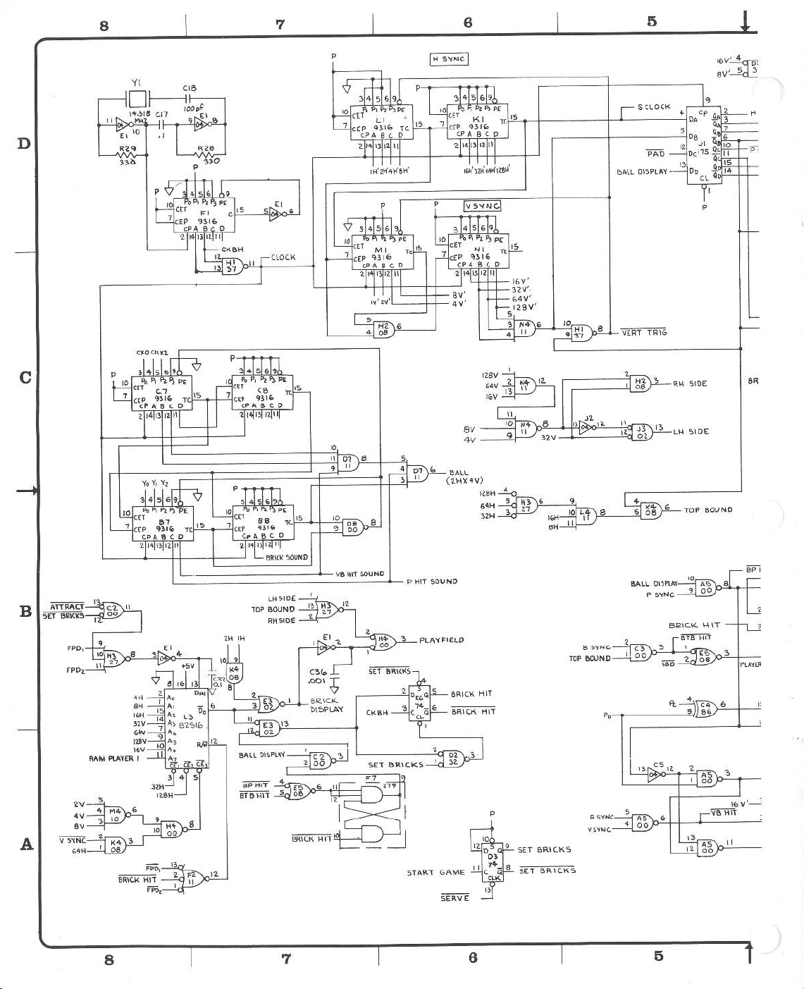
D
8
7
6
5
,4
16V~
av'---2ci.2
CLOCK
S
4-
-
DISPLA'I'
BALL
T~IG
VERT
c
B
ATIRAC.T
~
FP0
FPDz.
8R
BOUND
TOP
50\JNO
HIT
P
SID(
LH
BOUND
"TOP
SIDE
RH
1
PLA'fFIEl.D
BRICK
BRIC.K
Hl1
11
H
TOP
S'1NC.
B
WUND
Pp
BALL
DISPlA'I'
s'fNC
P
3
PLA'l't:~
fl
6
A
8
p
BRIC.KS
SET
BRIC.KS
GAME
STAR"T
7
6
SET
5
ii
Page 47

4
-
t-l
5'(NC.
>-'-'----loll-----'+:....&~
R51
scoAr. _
V
-+--~--
S'<NC
VS'tNC
_,.,RJS·v"-,~--"'
~-~K
C'2.'2.
IOµt
.-fYl
_l.
R42
L....J
+sv
3
VI
DE.0
VIDEO
E.ND
2
MF
SYM
4
'Pl2D'DUC.TIOW
B
REV
22
c
D
REV
E
REV
F
Rt.v
7
P~R
7
PER
PER
PER
DESCRJPTION
RE.L.EA
EC..N
ECN
ECN
tCN
~E-
2275.2Z7fo
2.4'7
I
252.5
z
s41
1
z5u,9
1
DR
'2.
,
3-//..-
;t'6'i-
w27f,c.
INITI
ALS
a
n
d
DATE
FTG
C
H
ECK
ENC
R
I?>
/?i,
G
7'-
D
3.9K
PLA't
Cp
6RICKHIT
p
V
SLOW
'"H
c
R.58
64H-~---:--....
32.11
s
)------'-''L
__
p
__
......__
BALL#A
BALL*B
BALL
V
SLOW
SH'·
-
__
.,._,.,c-=-::,.....
p
!------+__---___,,
INTERPRET
PER
USASI
UNL~
OTHERWISE
DIMENSIONS
TOLERANCES
FRACTIONS
•
ANGLES
..
.:1:.1
°
SURFACEANISH
CUR.RE.NT
THIS
DRAWING
YJ4
.S
C
H
INCHES
:
:t.
•
:t.
•a
ECKED
.I
.03
PRWECT
ENG
DOCUMENT
INEER
CONTROL
.
010
SPECIFIED
ARE
IN
ON
.:t.
l
/
16
.x
•
.xx
\,/"'
.xu
DATE
rZ
-
/S·75
\JE.R.SlOt-..1
)I\_
ATARI
SIZE
+SV
R~O
IK
'OiERVE
Yo
ATTRl\q
BALL
D
4
3
2
C37
C.12.8
Q6
o;;,4
YI
11
C
'!:1
8AllS
-01
ATARI INCORPORATED
14600
Los
Gatos,
SCHEMATIC
BREAK
DRAWJN
G
NO
004533
S4-
Winchester
California
OU\
1
EGL
-::-
Boulevud
95030
DIAGRAM
S
HEET
OF
R
B
A
EV
F
4
Page 48

PLl'.'<f.R
8
'Z.
7 6
p
p
5
p
p
D
c
5(T
BRICk'.S
Bil.LL
PLA"tER
eALL*o
tiA
'2.1-\
Ki
COUN'l 2
STAR'l
uP..IVIE
£ZFZG2
Al
Bl.
ci
02
p
H1
p
1°'121(HZ.
p
Gz
Dz
p
""
COUNI
I
Al
81
C.I
DI
s
2.
PLA't'E.e
NS
15
':J31Z
f
10
2.
MS
15
q~l'Z.
El
Fi
GI
HI
RAM
II
JI
Kl
PLA't't:R
LI
I
4H
2H
II
K.1
c;,
D1
I~\-\
SH
':.Tll.Ri
GAME
RAM
HORl'Z
SH
11
I~
HS
9~1'Z.
-
z
14
BRIO(.
p
Hli
-+5
PLA'
B
A
6)>.LL#C
8
02.
H<.
l'2
DI
HI
LI
32.11
LS
931(.
KS
931?..
E
10
I
S~
\!:)
10
15
E
10
4V
6'1
av
VERT
14
7
Page 49

4
3
2
1
'
LA'IE
PLA'1£R
Fl
FPDz
FPOl
p
tS
R2.3
411<.
FPD1
FD01
p
R
'2.
I
COUNT
COUNT
2
'2..
I
v
5'1i.c
2
I
J9
10
13
+s
•s
R48
ZlK
BP
CC.7
jut+
IS
14
+5
R
68K
C24-
l.uf
+
'2.
Q
0
A7
HIT
GAME
R39
47
FRE.E.
"TONE
'1
5
K
R~l
41K..
f".
·
~
F
RSO
\O
V
SYM
t-----11------
+5
K
O
L
CA
D
-
ESC
_Rl_P_r1
o
_
N
-----+---l---
C
H_
E
_C
K-_
E
_
NG
_R
G
_.
D
~3<o
41K
+
V
UN
REG
c
l..OC.K.TA.IL \A.l!.LE..
PLA'<ER
CONDI\
51<.
POT
PLA.'(E.R.
8
I
I
E>TB
01'-lL'(
~--
ION
HIT
AL'
I
PADDLE
+sv
---
_.
#
I
4
R33
-47
B
ATARJ
14600 Winche
~_
'
G-
a
t
o
-
s,
004~33
1
INCORPORATED
s
t
er Boule
_Cm_fu_m_~
9
-50-30
DIAGRAM
S
H
EE
1
var
T
d
______
'2.
_.P1,
R
EV
F
OF
4
PLA'<ER
l
NO
(SPDT)
S
'2..
RMAL
COCKTl\ll
CABINET
R16
IK
COND\TIONAL
SCORE.
D
AT
TR
R
OL
E
12.-1(,-75
...
)l
-A-
I\
D
'
T}.g!
I
l
____
J
SCHEMATIC
BREAKOUI
INTERPRET
T
HIS
D
RAWI
SI
Yl4
OTHERWISE
A
RE
=
.:t:.
l/
16
1°
NG
.S
CH
E
C
KE
SPE
CIFIED
IN
INCHES
ES
ON
:
.
x •
±
.I
.
xx"'
.:1:.
.
.
xxx
::
.t:.
D '
.._~~~~~--1
D
ES
I
G
N
ENG
0
3
P
ROJ
E
CT
.
ENG
010
rx>CU
M
E
N
T
CON
,'
1'~ED
..
..
..
I
NEER
I
NEE
2
PER U
SA
UNLESS
DIMENSIONS
TOLERANC
FRACTIONS
ANGLES
=.:1:.
SURFA
CE
FINISH\/"'
NEX
T A
SSY
3
Page 50

D
8
~c
.
+sv
7
4
6
tS
PLAY$/2.5f
2.
~
~
S3
5
ORZCREDIT
I
-~10
COIN
EGL
ANT.
QI
2N3
03
Z
I
JI
O
c
\W
c
B
START
PL~YER
I
'
START
PLA'1£~
2
I{
SCORE'
1
I
S
M56
I
2{:
$CORE
MSB'S
z.
.
2.
II
;-sv
---++-+-r--;-::
START
GAME
ATTRACT
-ATTRACT
1
$fART~
CR
O
DB
'
gy
ZCRSTART~
r
A
8
COIN
BONUS
7
6
5
Page 51

C.SW
CSW2.
4
COINitl
COIN°'*'2
+SV
CR4
14
IN
CR3
INCJl4
R)'l.
100
3
2
SYM
DESCRIPTION
MF
a
1
DATE
and
INITIALS
CHECK
D
RZf>
330
Q.
+-Sii
+sv
I
I
2)
Q<o
2N5\'}0
I
C.DIN
COUNTE.R
~
_J
_
i
c
t
p
LICO.HT
CRfDIT
2
B
Q4
A
MCRIOf>-1
G
R2.0
CR(OtT
'2.
OR
I
F~
~\OR2
RIG
'2.'l.0
c
470
GND
VAC
&.3
DRAWING
THIS
INTERPRET
Yl4.S
I
USAS
PER
SPECIFIED
OTHERWISE
UNLESS
DIMENSIONS
FRACTIONS
ANGLES
SURFACE
4
3
ARE
TOLERANCES
16
/
&1
•
*-lo
•
FINISH\,./"
IN
.x
.
.
ON
xx
xxx
INCHES
:
:t.
•
=
.I
03
.
*-
.010
"':t.
CONTROL
DOCUMENT
4d!£RQ(ED
2
CR£01T
I
12-16-"75
LIGHT
)I~
ATARI
SIZE
D
SCALE
ATARI
Winchester Boulevard
14600
Gatos,
Los
SCHEMATIC
BREAKOUT
.
NO
DRAWING
4
0
0
INCORPORATED
California 95030
Dl
3
O
SHEET
1
AGRAM
3
3
OF
F
A
4
Page 52

8
7
8
5
B
A
8
~
OIG>TAL
GNO
7
8
5
Page 53

l
4
I
3
I
.
2
MF
SYM
I
DESCRIPTION
REVISIONS
1
DRFTG
INITIALS
ind
I
CHECK
I I
DATE
"'I
I
ENGRG
D
-
c
l
NOTICE
CONFIDENTIAL:
cificwrltten~ofAtarilnc
==nis~~o:!~~~ann;t=t~
IJomie lo
E:t"::eru:!
uad.:'~~;i:,.~~~~"1:'.'
thkdnwingilputed
wrfttn
ponlloo
4
TO
ALL
PERSONS
~uction
me,
the
su~t
:r!°:1:"
qreement with o
.
RECEIVING
Forbidden
.,
LolG•t01
matter
of
the
dnwfna:
:o~t=n(.:X°'
~41
orthesubjectrn1tter1
r
writtm
pennil&jon from
THIS
without
or
U:Yr;st'~:r!
~-.:=
reofWaltllby
DR.AWING
tht1pe-
,
CalifOl'1Uli
any
desip
thecor·
+--
B
I~
~
!I
!ii
~
,_
!!!
~
·-
~
I~
r
INTERPRET
THIS
ORA
PER
USASI
YJ4.S
UNLm
OTHERWISE
DIMENSIONS
ARE
TOLERANCES
FRACTIONS
•
•I/16
ANGLES
•
:iclo
SURFACE
flNISH
\;"""
MATERIAL
.
NEXT
ASSY
APPLICATION
USED
ON
3
:
I
WING
SPECIFIED
IN
INCHES
ON
'
.
x••
.
x
x
• • .
.
xxx
•
DRAWN
B
Y
CHECKED
DESIGN
.
I
•
ENGINEER
03
PRQJJ;,CT
.
ENGINEER
DI
0
DOCUMENT
......
l!'llR""
P
'l
.._
2
CONTROL
DATE
1'2.·IE>-15
:2/tC/1<-
-
J1\_
ATARI
TITLE
SCHEMAT\C
BREAKOU\
SIZE
-
~
DRAWJNGNO
D
·
SCALE
I
ATARI
INCORPORATED
1%00
Winchester
Los
Gatos,
California
.
604'2::>33
I
1
Boulevard
95030
O\AGRAM
IF
SHEET
OF
4
I
A
+
...
Page 54

BREAKOUT
JI\.~
ATARI™
Innovative
sure
,
lei
____
,........_..
Rev.
A
B
c
n
E
Description
PER
REV
2276.
RF.V
2277
PER
2387
PFR
RF\/
PER
REV
ECN
ECN
i:rN
ECN
ASSEMBLY
Drawn
Checked
Proj.
ME
"----..----------------.-.11..-------------#---__.,I
....._.
2275.
22~~,234~
?471
2525
TITLE/
Eng.
nate
2/18/76
3-17-76
_
_
.
8
4
4-29-76
PARTS
Apprv.
.
76
ASSY,
SPECIFICATION
LIST
Rev.
F
BREAKOUT
Mech.
El
ec.
Description
PER
REV
P.
Eng.
Eng
ECN
C.
.
2547,
BOARD
256~
P/L
Pa.ge
_
~
Date
&[1.q
A004533-0l
3
of
1
REV.
F
Apprv.
{Jc,
!
Item
004532-01
1
2
10-5101
3 10-5102
10-5151
4
5 10-5185
10-52p7
6
7 10-5221
8 10-5470
9 10-5223
10-5273
10
10-5331
11
10-5392
12
10-5333
13
10-5471
14
10-5473
15
10-5561
16
10-5562
17
10-5683
18
10-5272
19
19-808W4PO
20
21
10-5123
Part
~umber
Qty.
1
3
15
3
1
1
3
1
1
2
3
5
1
2
6
1
1
1
4
l
1
Board
C.
P.
Resistor,
II
II
II
II
II
II
II
II
II
II
II
II
II
II
II
II
Resistor,
Resistor,
CARBON,
RES,
Carbon,
Carbon,
Wirewound,
orsCRTPTTON
!w,
II
II
II
II
II
II
It
II
II
II
II
II
II
II
II
II
!w,
5%,
!w,
II
II
II
II
II
II
II
II
II
II
II
II
II
II
II
II
5%,
II
II
II
II
II
II
II
II
II
II
II
II
II
II
II
II
5%
lOw
100
1
150
1.8M
2.7
220
47
22K
27K
330
3.9K
33K
470
47K
560
6K
5.
68K
2.7K
12K
OHM
OHM
K
OHM
OHM
OHM
OHM
OHM
OHM
OHM
OHM
OHM
OHM
OHM
OHM
OHM
OHM
OHM
OHM
OHM,
4
OHM
R25,27,32
Rl,5,6,11,12,13,
R24,30,34,35,44,
R
1
40
\
,;2.
4
1
R54
R49
R17,20,31
R33
R46
R47,48
R26,28,29
R41-43,51,52
R2
R16,Rl9
R22,23,36-39
R55
R3
R45
R7-10
R4
70%
R53
18,57
15,58
22
23
24
25
19-315103
24-250105
24-250106
24-250107
1
7
2
1
Trimpot,
Capacitor,
II
II
lOK
Elect.
R50
25V
uf,
1
11
II
lOuf,
lOOuf,
25V
25V
C14,15,24,26,27,29
C22,25
C2
,21
Page 55

F
Rev.
3
of
I !Page 3
P/LA004533-0l
BOARD
DESCRIPTION
P.C.
Otv.
Number
Part
Item
2
37-74279
62
BREAKOUT
SPECIFICATION
ASSY,
LIST
PARTS
TITLE
ASSEMBLY
555
4016
74279
Circuit,
Integrated
1
2
37-4016
37-555
63
64
9310
9312
6
6
37-9310
37-9312
65
66
9316
9602
11
37-9316
37-9602 4
67
68
LM380
LM323
1 Regulator
1
37-LM380
37-LM323
69
71
70
Sl
S2,3,4
DPDT
Switch,
Slide
1 Heats ink
1 Switch
3
66-024SPST
69-001
78-06001
72
73
74
CRES
#6-32x!
Phil,
Hd,
Pan
#6
Flat
Mach,
Screw,
Washer,
2
1608C
72
75-016 2
75
76
#6
Star
Int.
Washer, Lock,
75-056 2
77
.
CRES
#6-32
Hex,
Sil-Pad
Nut, Machine,
1
2
75-916C
78-16005
79
78
Yl
C37
lOOV
330pf,
MHZ
14.31818
Capacitor,Ceram~c,
Crystal,
1
1
27-101331
90-101
81
80
--
--
.F
3
REV
of
e 2
Pa
A004533-01
Pl L
BOARD
DESCRIPTION
P .C.
t •
SPECIFICATION
BREAKOUT
LIST
ASSY,
PARTS
Number
TITLE
Part
ASSEMBLY
Item
C23
25V
22uf,
II II
1
24-250226
26
27
Cl
25V
220uf,
II
II
II
II
24-250257 1
28
C31
C3
.
16V
25V
500uf,
8000uf,
II II
1
24-250507 1
24-160808
29
30
C20,33,35
Cl8, 4
C5-13,16,17,19,
C28,30,32,34
lOOV,
25V
25V
luf,
.Oluf,
O.
II
II
16
27-250104
32
Dipped Mica, lOOpf,
Capacitor,
2
28-101101
33
Ceramic,
Capacitor,
3
27-250103
31
,2
CR8
C36
CRl
25V
Ceramic, .OOluf,
ltl4001
Al4F
Diode,
Capacitor,
1
1
2 Diode,
27-250102
31-IN4001
31-Al4F
34
35
36
Ql
CR3-7
2N3644
IN914
Diode,
Transistor,
5
31-IN914
33-2N3644 1
37
38
Q6
Q2,3
Q4,5
2N5190
2N3643
MCR106-l
Transistor,
Transistor,
Transistor,
1
2
2
34-2N5190
34-2N3643
35-MCR106-l
40
41
39
7406
7402
7404
II
II
Circuit,
II
II
Integrated
7
37-7400
37-7402 4
37-7404 6
42
43
44
7408
II
II
37-7408 8
45
7410
II II
37-7410 2
46
7411
II
II
37-7411 4
47
7420
II
II
37-7420 1
48
7427
7430
II
II
II II
2
37-7427
37-7430 1
49
50
7432
II II
37-7432 2
51
7437
7448
II
II II
II
1
37-7437
37-7448 1
52
53
7474
7483
II
II II
II
12
37-7474
37-7483 2
54
55
7486
74107
II
II
II
II
9
37-7486
37-74107 1
56
57
74175
74192
II
II II
II
1
1
37-74175
37-74192
59
58
RAM
82Sl6
74193
II
II
II
II
1
3
90-7008
37-74193
61
60
Page 56

0
tfl.:I:
~
- . '
8
~
ci
~
~2~~
....
~~
q..
~
~
~
ll..
D
~
[
0
'7
~
~
;i
~
'4~e
~~"'
?"
:;
~
~
<t
<.)
. e " ,
• .
LI
~
• ' ,
• "
0 < ' ;
'
' .
,:
:;;l:!r o
:J
.<.
0 -
2
~~~
"'
:;i N
ll:
0
0
3~
- :i::
J :J
~
I-
u-,
<~
..
:i
:;E
"1
<II
~g
..
tfl
_J
_J
·
~
~
£ 9
4: Vl
r-
2
~
~
~~~1-S
~::'.:tG~:;:
~
c.J
..
Di
~
rl
i9
0
2
Ci:
_J
Cf_
r;::
-
_J
~"''
~
.-~
~~'.l
~<!~
2 A ' - • " • ' •··
""""'•
~
~&&s·"
~
uO'~>
ol~r:i22
' .
..
..
, '"" . ,,,,'R
,.?.3\b
""""
·'"'
·
. ,
. "' "'"
'''.
,,
[111
"'""'
,.b,
\
11
,
t,.
. .
''""'
""
1111
11
~
~·
.
.
;
'"'"
~
m~'
,r
-:0°
1,
..
r"'1
J.
N j
··
•
'""' "'"'
.·
· ,,......,...
···
0
I""
'4""
::::01
""
. "
11!1
.
"'"'"
,,,
93iz"
Mf
•
~
,.,
. .
·'
"'
•.
l•·i
;~'"
'
-0
0
-.;:::::
-
----,-
- ,
0
0
2
P!'.
w
>
lfi
r--
2
cJ
Cl!'.
(!'.'.
uJ
:::J
~
~
~
I~
s
I
C\l
~
~
I
~
~
~
~
~
i .
~
~
~
i~
U.
~
~
:n
~
6~~
2~~
~.
!tt.!2
'i
:!
E f
~
=~h1~
~~~~1J?l1hU
1
~M'·
"'"'
.:;
ti
fj~
l~g
.).!i.ir•
lf!f
.... !:5
l~
'01·
§~!
iji!
g
~J!f-i!Eil'N
~
!.i11~m
ile
~i§
~
:i3lE.;
1
iii'H~,g
h]z~t
~
i:i~"'
"i~.U~Jg
1
mt~f.P""!
_,,,_
lu~
~lE
§
a:
~
~
~
w a
w a
if)
<(
_J
~
~
i
.;,
It
,,.,
a
l!1
I
~~~
~
I'-
~
·
(!'.]
Q:'.:
~Q
~
~~~
'<~§
i:i,q
i!;
~~~
~u
~
s
di
~
2 f-
cJi
tfl a
uJ
<[,
':J.
12-
:::J
uJ
<
:;:
~
~
~
<(
-
~
tJ
'
0
0
~~·~
r<Y
~
<
g
~LI-
;
...
....
·' .
---.-
..
.
Page 57
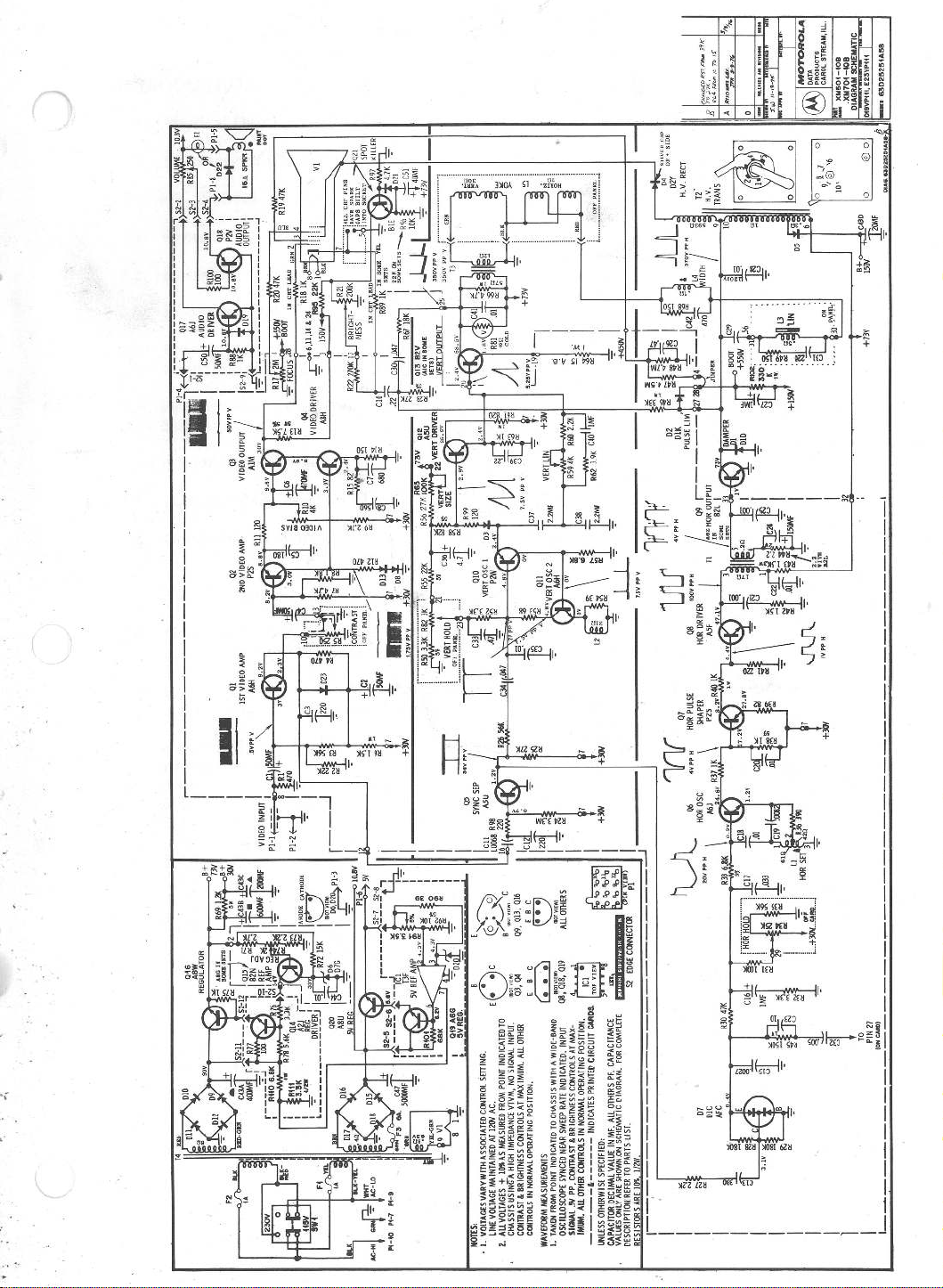
•
"
1~·
J1K
r
1
7'
,..
n
! ·
.
l
10
.ll?!
#,...,,,.,,,.,.,F
~.fj~
l
k
IRllO........
o
B
I
IA
'
!
D2Y
RECT
.
H.I/
I
0
0
.
2 4
I
S
TZ
H.V.
T~AN
0
0
p
L~f:;Ig~
~
~
:
!
l
.
.
~
e
~
~l
~.
~
~
~-
-
~
~.~~--~
.
.
.
....
.
.
...
L
---<.~
-
..-
-
04
@o
o
iJ
PD25254A51.
CHAI
J\J\.
+»I
1fY
-----
.
Ill-Ii
I~
ARE
r~------------------~
RESISTORS
Q6
s
~
~
~1~ I~
D7
DIC
AFC
~
~
~
IV
.
3
I
I
I
I
I
I
I
I
I
~v
1
I
1
~~--------~~----------------------------·
+»r'
~
~
~
1
2
j
IC!.?,
0)
i
c
016
'-
EW
B
VT
_;
01
013.
E
~
11
.
y..__,...'(C
?>~
'2
B
09
E
C
c
•
04
B
'""'
B
•
o•
E
TO
INDICATED
SETTING.
,,
POINT
.
FROM
AC
CONTROL
12W
AT
MEASURED
ASSOCIATED
IOllAS
WITH
MAINTAINED
VARY
VOLTAGE
VOLTAGES+
LINE
ALL
VOLTAGES
I.
2.
NOTES:
•
01
03,
E
11
~
.
OTHER
INPUT
ALL
.
SIGNAL
.
NO
MAXIMUM
l/TYM,
AT
POSITION
CONTROLS
IMPEDANCE
OPERATING
HIGH
A
NORMAL
BRIGHTNESS
IN
&
USING
MEASUREMENTS
CONTRAST
C<»lTROLS
CHASSIS
WAVEFORM
0
1
1
I
I
I
AU"'orn[Rs
~c~,:
cll8~'019
o
T
os~
.
MAX-
~~:~ND
.
AT
1~A~E~
CONTROLS
l~N~~~~~~~~~~Ng,:g~\~l~os
BRIGHTNESS
&
CONTRAST
'
pp
JY
SIGNAL
~~~u~~~~~~~~~i;:;~Ds~~~p~~~~~N~
~MUM.~~~:~~~~
1.
I
I
Pl
CONNECTa!
EDGE
sz
COMPLETE
FOR
CAPACITANCE
.
.
PF
PIAGRAM
OTHERS
ALL
Hs~TIC
1
MF.
:
IN
VALUE
SPECIFIED
DECIMAL
OTHERWISE
lJjl[SS
CAPACITOR
~t}~~P~g~~~E~~~w~~'i\sE
Page 58

Page 59

)
Page 60
Copyright
©
1976
by
Atari,
Inc.
JI
SUNNYVALE
1265
, CALIFORNIA
0
A
JI\_
ATARI
ATARI
BORREGAS
94086
W
arner Commun1cdt1ons
®
INC
AVENUE
408
/
7
Company
45-2000
•
TELEX
35-7
488
Page 61

-·---
i.
---····
...
~
!
!
f
I
I
I
!
L
..
,..
.....
\
I
'
·
i
..
.
'
i,.)
~
I:,.
!
I
.,
-:
.
..
i
t
(
..
.
I'
...
,l
'
I
I
t
I
l
t
I
f
I
()'
'
I
~-
'
I
,
T
...
..
''(
,·
,
•.,
,
.
' .
..
~_,..
-'r·"
\
I
,;:1
.
·
I
·
·r·
:.-
,.
\.{.
t
I
I
r
I
I
.
-~
,-
I
!
.
)
·---
....
-
......
·--.~~-~
-
..
'
i
-
.
..
_,,..
~-
~
-
...........
·--·
·--
·
··-·
..
-··--·
..........
-........
"-..--
....
·~--·
·
·
-·
-
---
-
·--
--
..
t
i
l
Page 62

I
N
0
co
~
AFTER
GAME
PLAY
•EXTENDED
BRICKS 100 POINTS.
lO
0
0
KNOCK
AFTER
MANY
AND
ENDS
•GAME
START FORTH,
BALL
LIGHTED
SERVE BUTTON AS POSSIBLE. WILL SOUND.
•PRESS
•PRESS
ARE SERVED
BALLS
TO EACH PLAYER.
AND
TO MOVE 3
KNOB
PADDLE BACK
•TURN
GAMES.
"ONE-PLAYER
GAME.
ONE.
"TWO-PLAYER TO SERVE
PLAYER
START" FOR TWO, BUTTON DOWN AS
•PRESS
ONE
•PRESS
START" FOR
TWO PLAYER
 Loading...