

Page 1

TM-143
3rd printing
O
« Λ . .
SI ^ Λ
/ > Y
S / . e r f . '
V
Operation, Maintenance
and Service Manual
Complete with Illustrated Parts Lists
Page 2
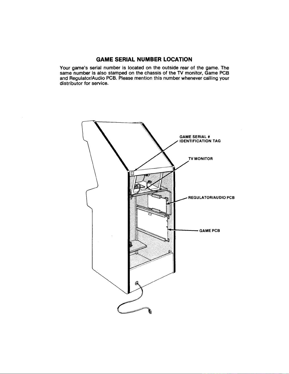
GAME SERIAL NUMBER LOCATION
Your game’s serial number is located on the outside rear of the game. The
same number is also stamped on the chassis of the TV monitor, Game PCB
and Regulator/Audio PCB. Please mention this number whenever calling your
distributor for service.
Page 3

Published by:
ATAR I IN C
1265 Borregas Avenue
P. O. Box 427
Sunnyvale, California 94086
Operation, Maintenance
and Service Manual
Complete with Illustrated Parts Lists
Copyright © 1979 by Atar i, Inc. All rights reserved
No part of this publication may be reproduced by any mechanical,
photographic, or electronic process, or in the form of a phonographic re
cording, nor may it be stored in a retrieval system, transmitted, or other
wise copied for public or private use, without permission from the publisher.
Lithogra phe d in the U.S.A.
1J
A
ATARI
A W a r n e r C om m unica t i ons Comp a ny
Page 4
Ast e roid s
Table of Contents
1 Location Setup
A. New Parts................................................................................................... 1
B. Game Inspection....................................................................................... 3
C. Game Installation....................................................................................... 3
1. Voltage Selection...............................................................................
2. Interlock and Power On/Off Switches
3. Game Fuses.........................................................................................5
D. Self-Test Procedure.....................................................................................5
E. Game P lay...................................................................................................8
1. Attract Mode.........................................................................................8
2. Ready-to-Play M od e.............................................................................8
3. Play Mode.............................................................................................8
4. High Score Initial M od e.......................................................................9
..............................................
. .
3
. .
3
2 Maintenance and Repair
A. Cleaning................................................................................................... 12
B . Fuse Replacement.....................................................................................12
C. Opening the Control Panel .......................................................................12
1. Leaf Switch Replacement...................................................................12
2. LED Switch Replacement...................................................................12
D. TV Monitor Replacement...........................................................................14
E. Printed Circuit Board Replacement
F. Fluorescent Tube Replacement
G. Game Operation.........................................................................................16
........................................................
.............................................................. 1 6
3 Illustrated Parts Lists
15
ii
Page 5
Lis t of Illustrations
Figure 1 Overview of G am e.................................................................................. 2
Figure 2 Installation Requirements...................................................................... 3
Figure 3 Power Supply.......................................................................................... 4
Figure 4 Interlock and Power On/Off Switches.................................................... 4
Figure 5 Location of Self-Test Switch, Volume Control and Option Switches . 5
Figure 6 Self-Test Procedure................................................................................ 6
Figure 7 Option Switch Settings.......................................................................... 7
Figure 8 Opening the Control Panel ....................................................................13
Figure 9 TV Monitor Removal................................................................................14
Figure 10 Game and Regulator/Audio PCB Replacement
Figure 11 Fluorescent Tube Replacement............................................................16
Figure 12 Power Distribution..................................................................................17
Figure 1 3 Signal Distribution..................................................................................18
Illustr a t ed Parts Lists:
Figure 1 4 Final Assembly........................................................................................20
Figure 1 5 Control Panel Assem bly........................................................................22
Figure 16 Asteroids Game PCB Assem bly
Figure 17 Regulator/Audio PCB Assembly............................................................28
Figure 18 Power Supply Assembly for X-Y Gam es................................................30
Figure 19 Main Harness and Component Assembly............................................32
Figure 20 Fluorescent Light Assem bly..................................................................33
Figure 2 1 Coin Door Assem bly..............................................................................34
Figure 22 Front Bezel Assembly............................................................................36
Figure 23 New Coin Door........................................................................................38
........................................................... 24
...................................
15
Ast er o id s
iii
Page 6
Ast er o id s
---------------------------------------- NOTE----------------------------------
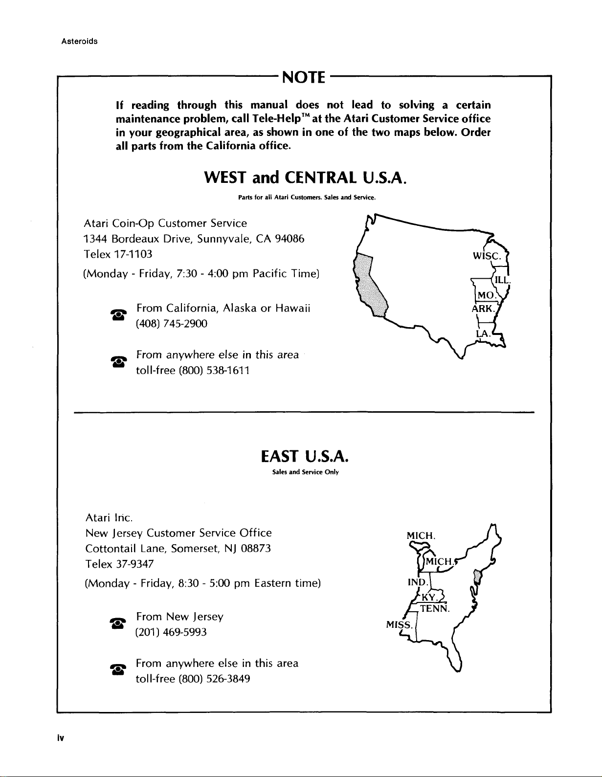
If reading through this manual does not lead to solving a certain
maintenance problem, call Tele-Help™ at the Atari Customer Service office
in your geographical area, as shown in one of the two maps below. Order
all parts from the California office.
WEST and CENTRAL U.S.A.
Parts for all Atari Customers. Sales and Service.
Atari Coin-Ορ Customer Service
1344 Bordeaux Drive, Sunnyvale, CA 94086
Telex 17-1103
(Monday - Friday, 7:30 - 4:00 pm Pacific Time)
From California, Alaska or Hawaii
** (408) 745-2900
From anywhere else in this area
** toll-free (800) 538-1 611
EA S T U.S.A.
Sales and Service Only
Atari Inc.
New Jersey Customer Service Office
Cottontail Lane, Somerset, NJ 08873
Telex 37-9347
(Monday - Friday, 8:30 - 5:00 pm Eastern time)
From New Jersey
** (201) 469-5993
From anywhere else in this area
* * toll-free (800) 526-3849
Page 7
A. New Parts
The Asteroids game has three new parts. If you
have worked on Atari games in the past, then you
should be aware of these important differences. The
new parts are:
• Power Supply Assembly. It covers a wider
voltage range than before, has higher reliability,
a smaller overall size, and all fuse numbers and
fuse amperages are marked directly on the metal
chassis.
• Game PCB Circuitry and TV Monitor. Most video
games to date have used the raster scan method
of display. This game uses vector generation
with X and Y axes to allow greater contrast, a
greater number of moving objects on the screen,
and lines at any angle to be “drawn” on the
screen.
Throughout this manual, wherever one of these
three new parts is mentioned, you will see this sym
bol in the page margin:
Page 8

Ast e roid s
Figure 1 Overview of Game
2
Page 9
Ast e roid s
B . Game Inspection
This new game is ready to play upon removal from
the shipping carton. However, your careful inspec
tion is needed to supply the final touch of quality
control. Please follow these steps to help us insure
that your new game was delivered to you in good
condition.
NOTE
Do not plug the game in yet!
1. Examine the exterior of the game cabinet for
dents, chips, or broken parts.
2. Unlock and open the access panel of the
cabinet and inspect the interior of the game as
follows:
a. Check that all plug-in connectors (on the
game harness) are firmly seated. Replug
any connectors found unplugged. DON’T
FORCE CONNECTORS TOGETHER. The
connectors are keyed so they only go on in
the proper orientation. A reversed edge
connector will damage a PCB.
b. Check that all plug-in integrated circuits
on the game PCB are firmly seated in their
sockets.
A WARNING
To avoid possible unpleasant electrical
shock, do not touch internal parts of the
TV monitor with your hands or metal ob
jects held in your hands!
C. Game Installation
Figure 2 Installation Requirements
Power
Temperature
Humidity
Space Required
Game Height
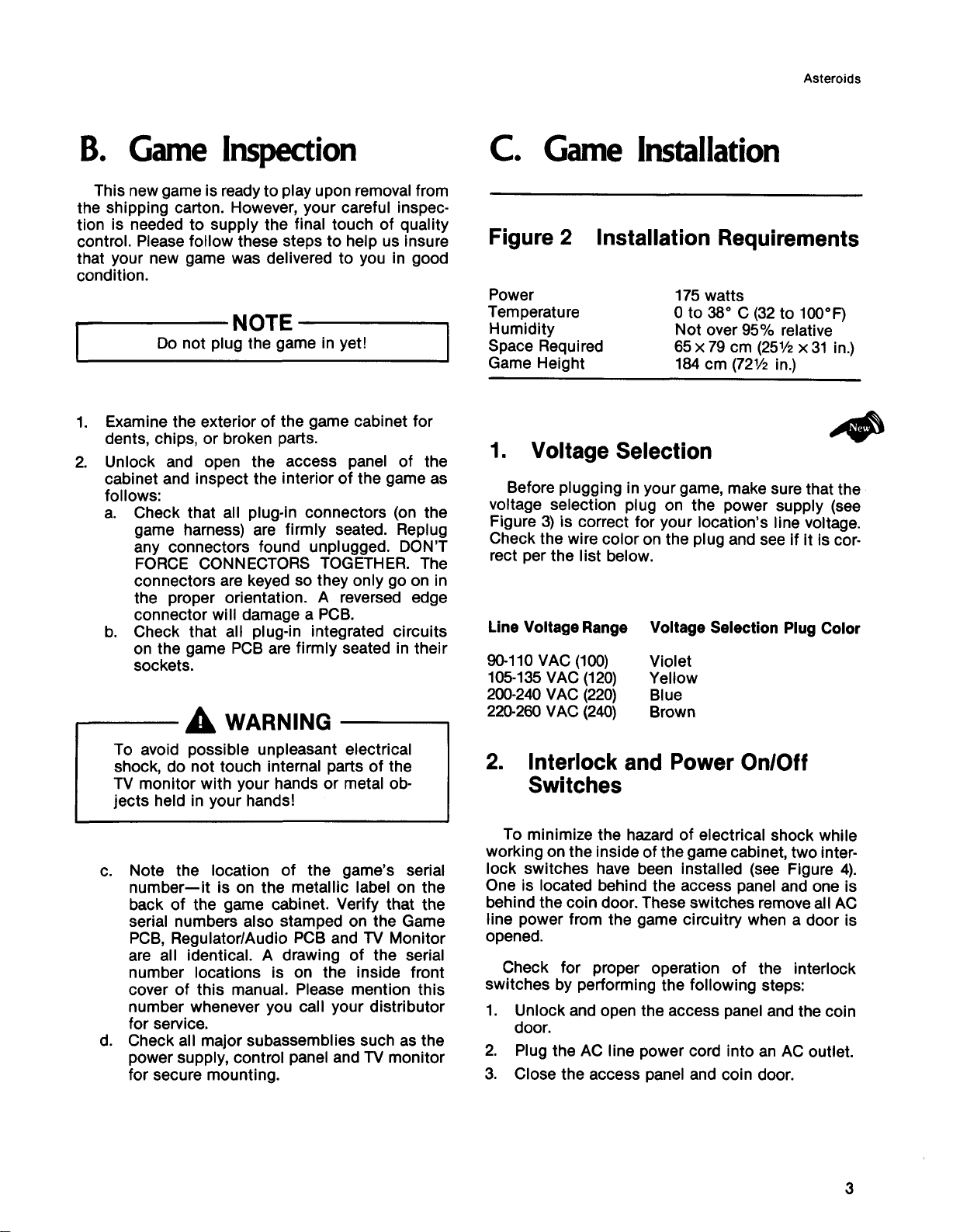
1 . Voltage Selection
Before plugging in your game, make sure that the
voltage selection plug on the power supply (see
Figure 3) is correct for your location’s line voltage.
Check the wire color on the plug and see if it is cor
rect per the list below.
Line Voltage Range Voltage Selection Plug Color
90-110 VAC (100) Violet
105-135 VAC (120) Yellow
200 - 240 VAC (22 0) Blue
220 - 260 VAC (240) Brown
2. Interlock and Power On/Off
Switches
17 5 watts
Oto 38° C (32 to 100°F)
Not over 95% relative
65 x 79 cm (251/2 x 31 in.)
184 cm (721/2 in.)
c. Note the location of the game’s serial
number— it is on the metallic label on the
back of the game cabinet. Verify that the
serial numbers also stamped on the Game
PCB , Regulator/Audio PCB and TV Monitor
are all identical. A drawing of the serial
number locations is on the inside front
cover of this manual. Please mention this
number whenever you call your distributor
for service.
d. Check all major subassemblies such as the
power supply, control panel and TV monitor
for secure mounting.
To minimize the haz ar d of electrical shock while
working on the inside of the game cabinet, two inter
lock switches have been installed (see Figure 4) .
One is located behind the access panel and one is
behind the coin door. These switches remove all AC
line power from the game circuitry when a door is
opened.
Check for proper operation of the interlock
switches by performing the following steps:
1. Unlock and open the access panel and the coin
door.
2. Plug the AC line power cord into an AC outlet.
3. Close the access panel and coin door.
3
Page 10
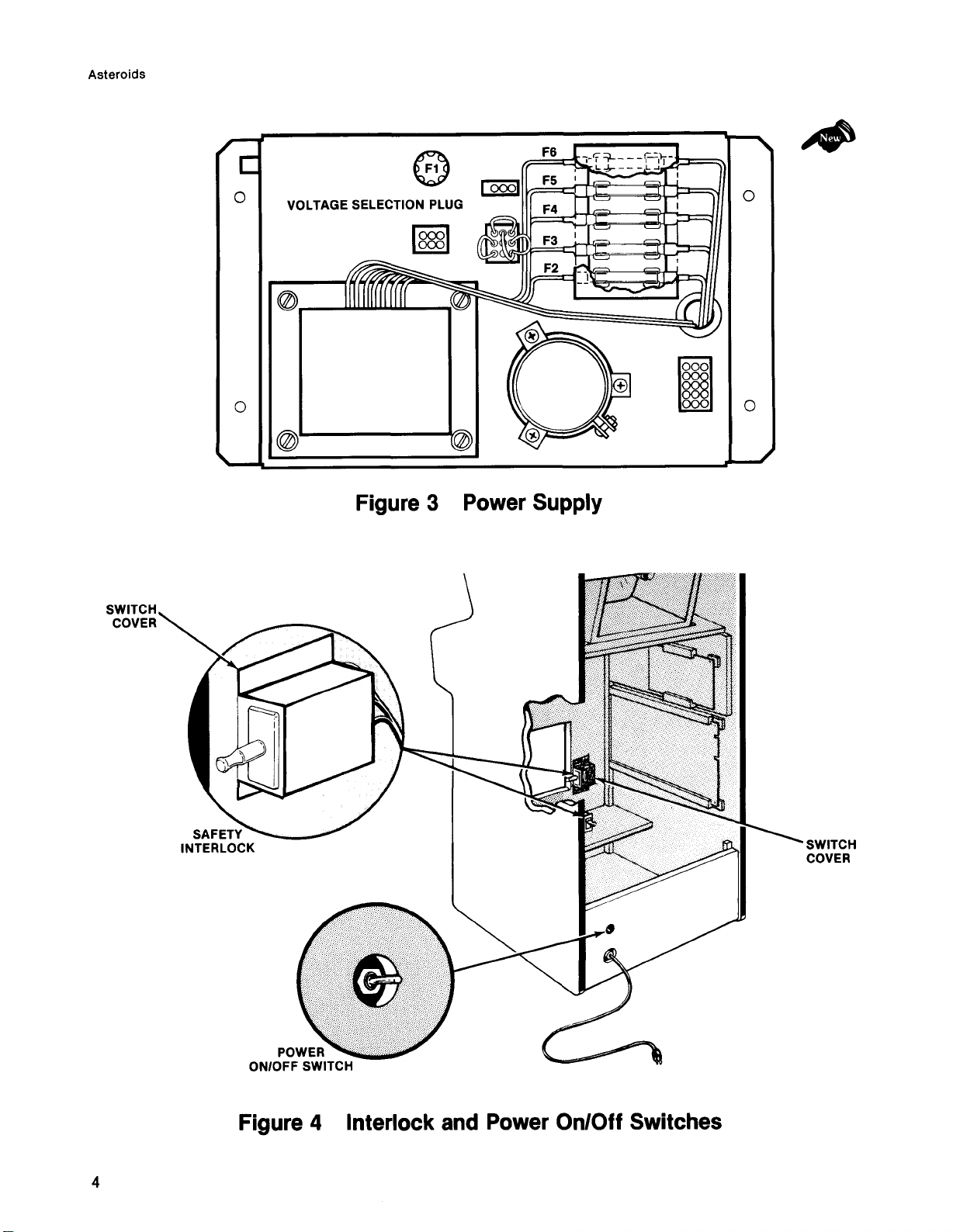
Figure 3 Power Supply
Figure 4 Interlock and Power On/Off Switches
Page 11
Ast er o id s
4 . Set the power on/off switch to the on position.
Within 30 seconds the TV monitor should
display a picture.
5 . Slowly open the rear access panel. The TV
monitor picture should disappear when the
panel is opened approximately 2.5cm ( 1 inch).
Close and lock the access panel and repeat this
step with the coin door.
6 . If the results of step 5 are satisfactory, the inter
lock switches are operating properly. If the TV
monitor doesn’t go off as described, check to
see if the corresponding interlock switch is
broken from its mounting or stuck in the on
position.
3. Game Fuses
For continued protection of your game, as well as
for the safety of the players, fuses must be replaced
only with fuses with identical ratings. These ratings
are shown in Figure 18. See the Schematic Drawing
Package for fuse functions.
Information on the TV monitor fuses is contained
in the TV monitor manual that is supplied with this
game.
D. Self-Test Procedure
This game will test itself and provide data to
demonstrate that the game’s circuitry and controls
are operating properly. The data is provided on the
TV monitor and the game speaker; no additional
equipment is necessary.
Part of the self-test procedure includes a display
of the operator-selectable game options. Therefore,
we suggest you run the self-test procedure anytime
you need to change the game’s options.
To run the self-test, follow the instructions out
lined in Figure 6.
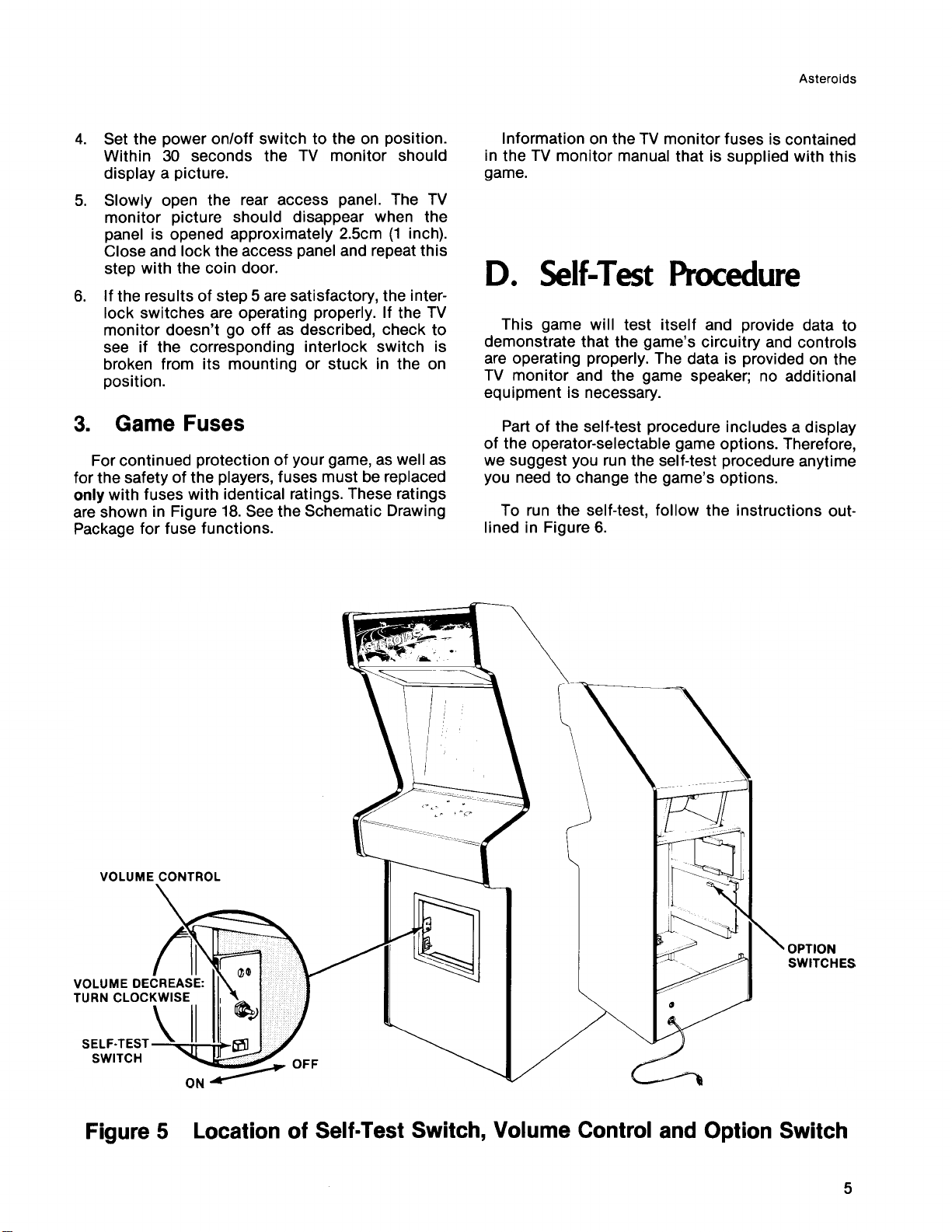
Figure 5 Location of Self-Test Switch, Volume Control and Option Switch
5
Page 12
Ast e roid s
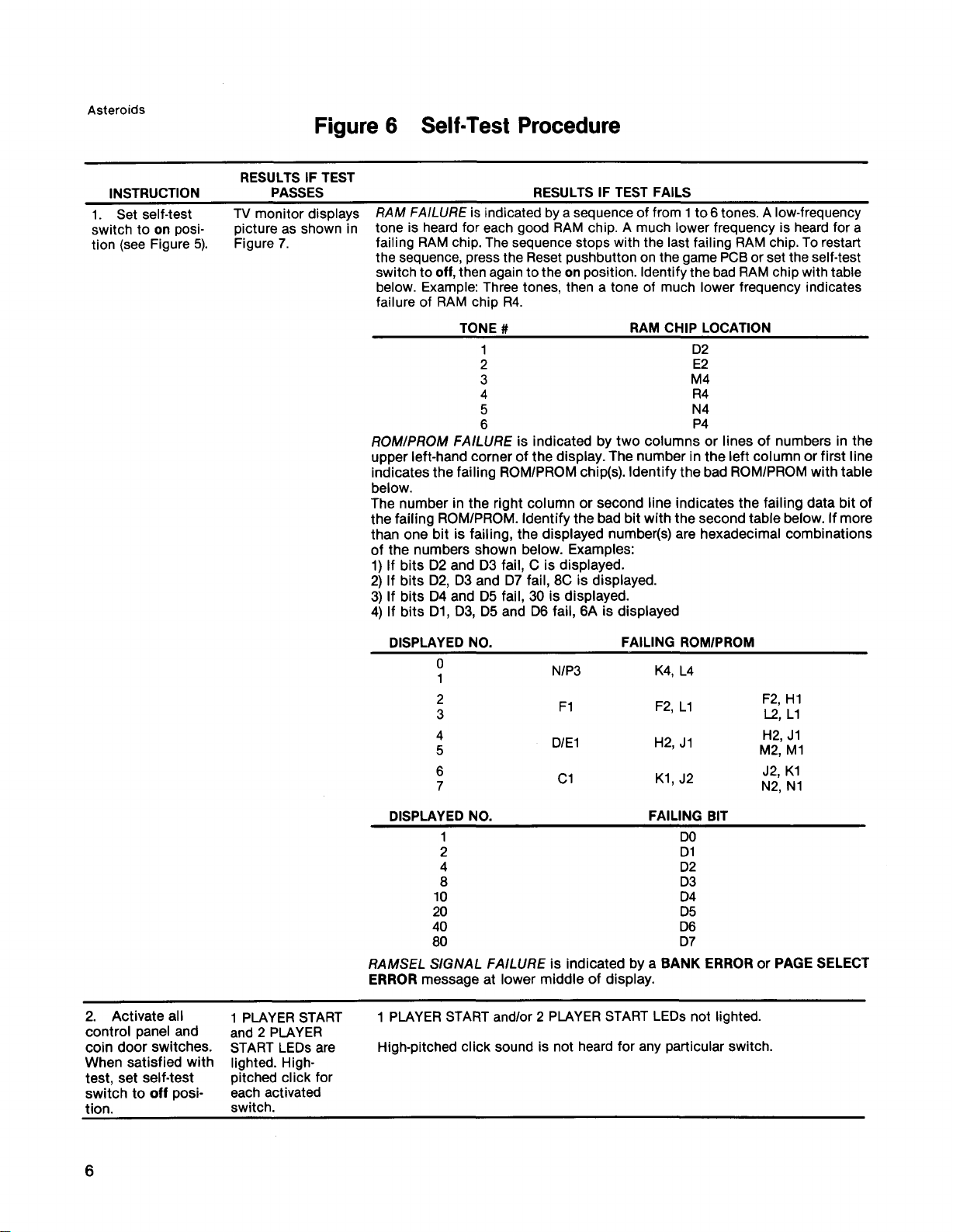
Figure 6 Self-Test Procedure
INSTRUCTION
1. Set self-test
switch to on posi
tion (see Figure 5) .
RESULTS IF TEST
PASSES
TV monitor displays
picture as shown in
Figure 7.
RESULTS IF TEST FAILS
RAM F A I L U R E is indicated by a sequence of from 1 to 6 tones. A low-frequency
tone is heard for each good RAM chip. A much lower frequency is heard for a
failing RAM chip. The sequence stops with the last failing RAM chip. To restart
the sequence, press the Reset pushbutton on the game PCB or set the self-test
switch to off, then again to the on position. Identify the bad RAM chip with table
below. Example: Three tones, then a tone of much lower frequency indicates
failure of RAM chip R4.
TO N E #
RO M/P RO M FA I LURE is indicated by two columns or lines of numbers in the
upper left-hand corner of the display. The number in the left column or first line
indicates the failing ROM/PROM chip(s). Identify the bad ROM/PROM with table
below.
The number in the right column or second line indicates the failing data bit of
the failing ROM/PROM. Identify the bad bit with the second table below. If more
than one bit is failing, the displayed number(s) are hexadecimal combinations
of the numbers shown below. Examples:
1) If bits D2 and D3 fail, C is displayed.
2) If bits D2, D3 and D7 fail, 8C is displayed.
3) If bits D4 and D5 fail, 30 is displayed.
4) If bits D1, D3, D5 and D6 fail, 6A is displayed
RAM CHIP LOCATION
D2
E2
M4
R4
N4
P4
2. Activate all
control panel and
coin door switches.
When satisfied with
test, set self-test
switch to off posi
tion.
1 PLAYER START
and 2 PLAYER
START LEDs are
lighted. High-
pitched click for
each activated
switch.
DISPLAYED NO. FAILING ROM/PROM
0
1
2
3
4
5
6
7
DISPLAYED NO. FAILING BIT
1
2 D1
4
8 D3
10
20 D5
40 D6
80 D7
RA MS EL SI GNA L FA I L UR E is indicated by a BANK ERROR or PAGE SELECT
ERROR message at lower middle of display.
1 PLAYER START and/or 2 PLAYER START LEDs not lighted.
High-pitched click sound is not heard for any particular switch.
N/ P3
F1
D/E1
C1
K4, L4
F2, L1
H2, J1
K1, J2
DO
D2
D4
F2, H1
L2, L1
H2, J1
M2, M1
J2, K1
N2, N1
6
Page 13
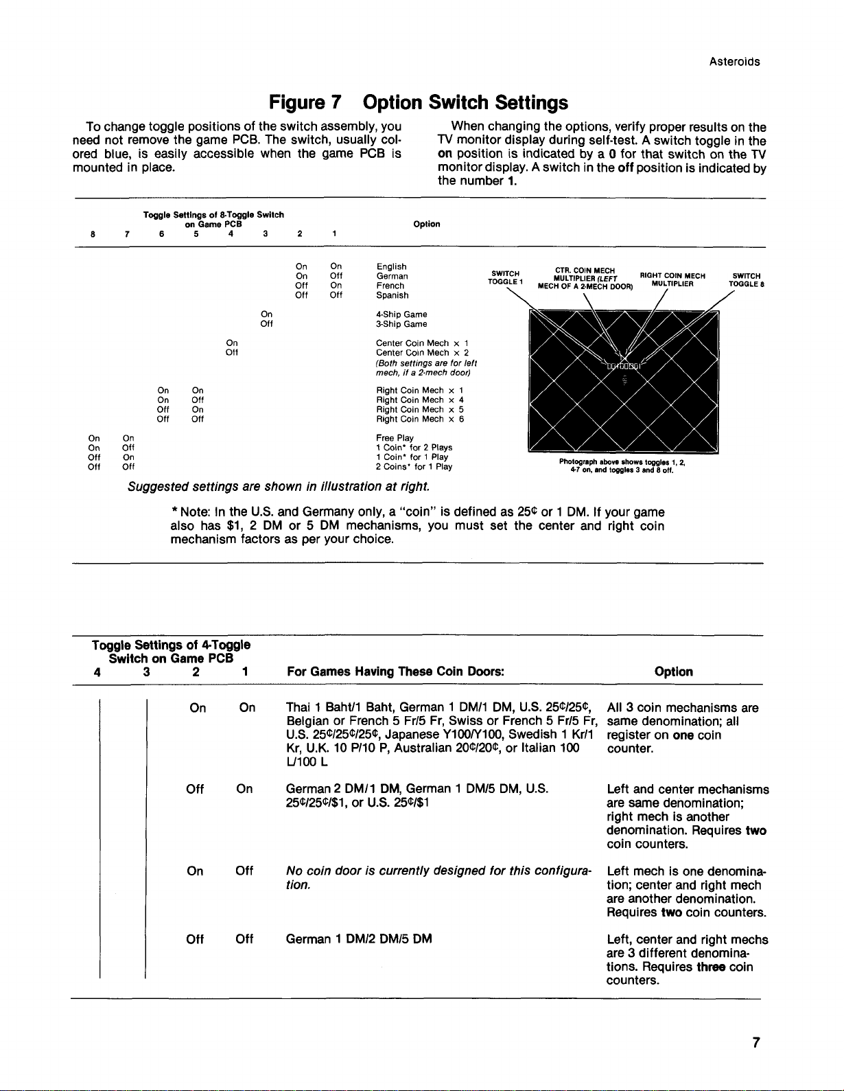
Figure 7 Option Switch Settings
To change toggle positions of the switch assembly, you
need not remove the game PCB. The switch, usually col
ored blue, is easily accessible when the game PCB is
mounted in place.
Ast e ro i d s
When changing the options, verify proper results on the
TV monitor display during self-test. A switch toggle in the
on position is indicated by a 0 for that switch on the TV
monitor display. A switch in the off position is indicated by
the number 1.
Toggle Settings of 8-Toggle Switch
7 6 5 4 3 2
On
On
On
Off
On 1 Coin* for 1 Play
Off
Off Off
on Game PCB
On
On
Off
On
On
Off
Off
Off
On
Off
On
011
On On Right Coin Mech x 1
On Off Right Coin Mech x 4
Off On Right Coin Mech x 5
Off Off
Sugg ested settings ar e shown in i llust rat i on at r i g ht.
* Note: In the U.S. and Germany only, a “coin” is defined as 25® or 1 DM. If your game
also has $1, 2 DM or 5 DM mechanisms, you must set the center and right coin
mechanism factors as per your choice.
Option
English
German
French
Spanish
4-Ship Game
3-Ship Game
Center Coin Mech x 1
Center Coin Mech x 2
(B oth settin gs are for left
mech , if a 2-mech doo r )
Right Coin Mech x 6
Free Play
1 Coin* for 2 Plays
2 Coins* for 1 Play
SW ITCH CTR· C 0 IN ME CH
TO GG LE 1 M U LTIPLIER (LEFT
MEC H O F A 2-MEC H D OOR )
Photog raph above shows toggles 1, 2,
4-7 on, and to ggles 3 and β off.
RIGHT C O IN MEC H
MU LTIP LIER
Toggle Settings of 4-Toggle
Switch on Game PCB
4 3 2 1
On On Thai 1 Baht/1 Baht, German 1 DM/1 DM, U.S. 25Φ/25Φ,
Off On German 2 DM/1 DM, German 1 DM/5 DM, U.S.
On Off No coin d oor is c ur re nt ly d esign ed for t hi s confi gura
Off Off German 1 DM/2 DM/5 DM
For Games Having These Coin Doors:
Belgian or French 5 Fr/5 Fr, Swiss or French 5 Fr/5 Fr,
U.S. 25Φ/25Φ/25Φ, Japanese Y100/Y100, Swedish 1 Kr/1
Kr, U.K. 10 P/10 P, Australian 20 1/20®, or Italian 100
L/100 L
25<t/25< t/$1, or U.S. 25<t/$1
tion .
Option
All 3 coin mechanisms are
same denomination; all
register on one coin
counter.
Left and center mechanisms
are same denomination;
right mech is another
denomination. Requires two
coin counters.
Left mech is one denomina
tion; center and right mech
are another denomination.
Requires two coin counters.
Left, center and right mechs
are 3 different denomina
tions. Requires three coin
counters.
7
Page 14
Ast e ro i d s
E. Game Play
the center of the display. Four large asteroids ap
pear and drift in from the outer edges of the display.
Atari’s Asteroids game has five possible modes
of operation: Attract, Ready-to-Play, Play, High
Score Initial, and Self-Test. Self-test is a special
mode for checking the game switches and com
puter functions. You may enter this mode at any
time. When entered, all game credits are cancelled.
1 . Attract Mode
The attract mode begins when power is applied to
the game, after a play or high score initial mode, or
after self-test. This mode is continuous and is only
interrupted when a coin is inserted and accepted or
when in self-test. In this mode, the TV monitor
displays two possible pictures. Both pictures have
three score values across the top of the screen and
a message that states the number of coins for a
game. The middle score represents the high score
to date. The left score is for player 1. The right score
is for player 2.
One picture displays asteroids and an occasional
enemy spaceship “ floating” across the screen. The
second picture displays up to 10 of the highest
scores since the game was last powered up or since
the last self-test. These two displays alternate every
16 seconds.
2. R e a d y- to - P la y Mode
This mode begins when sufficient coins hav e
been accepted for a one- or two-player game. It ends
when the 1 PLAYER START or 2 PLAYER START
pushbutton is pressed. When this mode begins, the
message
the center score at the top of the screen. The
displayed pictures are otherwise the same as those
shown in the attract mode.
PUSH START flashes immediately below
3. Play Mode
If the 2 PLAYER START pushbutton is pressed,
the following picture is displayed: the PLAYER 1
and PLAYER 2 scores become 00, and the number
of ships for the game appears below each score.
The player 1 score also flashes as the message
PLAYER 1 appears below the high score to date.
Two seconds after the 2 PLAYER START pushbut
ton is pressed, the PLAYER 1 message disappears.
The game ship for player 1 appears at the center of
the display as four large asteroids appear and drift in
from the outer edges of the display.
By pressing the LEFT ROTATE and RIGHT
ROTATE pushbuttons on the control panel, the
player may aim a spaceship toward any of the
asteroids. By pressing the FIRE pushbutton, the
player may shoot at the asteroids.
When shot, each large asteroid divides into two
medium-sized asteroids and the game adds twenty
points to the player’s score. Medium-sized
asteroids, when shot, divide into two small-sized
asteroids, and the player receives fifty points. Small
sized asteroids, when shot, will completely disap
pear, and the game awards 100 points to the player.
When players have shot all asteroids, a new set of
large asteroids again appear and drift in from the
outer edges of the TV monitor display. At the begin
ning of the game, four large asteroids appear. At the
beginning of the next cycle when large asteroids
reappear, there are six, the next time eight, and
thereafter ten— to increase player challenge.
At any time during game play, a flying saucer may
appear from either side of the display. The game
awards players 200 points for shooting a large
saucer and 1000 points for a small saucer. (The latter
is a smaller target for players, though not any faster
moving than the large one. It also shoots more ac
curately.)
The play mode begins when either start push
button is pressed. The mode ends when the player's
last ship of the game is lost.
If the 1 PLAYER START pushbutton is pressed,
the following picture is displayed: the PLAYER 2’s
score disappears; the PLAYER 1’s score becomes
00 , and the number of ships (3 or 4, depending on
the operator’s setting) for the game appears below
that score. The message PLAYER 1 also appears
below the high score to date. Two seconds after
pressing the 1 PLAYER START button the PLAYER 1
message disappears, and the game ship appears at
8
The player’s objective in the game is to shoot and
destroy as many asteroids as possible before all his
or her spaceships are destroyed. A ship is destroyed
if an asteroid or saucer smashes into it, or if a flying
saucer shoots it. To prevent losing a ship, the player
may press the THRUST pushbutton to move out of
the path of an asteroid or saucer. As an emergency
maneuver, players can press the HYPERSP ACE
pushbutton: the ship disappears and reappears at a
random location on the display— however, possibly
right on top of, or in the path of, an asteroid. The
ship may also explode on reentry.
Page 15
A st eroi ds
The game awards an extra ship each time a
player’s score reaches multiples of 10,000; i.e., one
ship is awarded at 10,000 points, another ship at
20,000 points, etc.
When the last ship of the game is destroyed, the
message GAME OVER appears below the high
score. This message remains for 3 seconds before
the high score initial mode begins.
4. High Score Initial Mode
At the beginning of the high score initial mode,
the player instructions appear at the top of the
screen, and A
the display. Players enter initials one character at a
____
appears at the lower center of
time. By pressing the LEFT ROTATE pushbutton,
the displayed character steps through the alphabet
from A to Z. By pressing the RIGHT RO TATE
pushbutton, the character steps backwards through
the alphabet from A to a blank, then from Z to A.
Once the game displays the desired letter, players
should press the HYPERSPACE pushbutton to
record the letter; then an A appears in the next
space.
If players need only two letters for their initials,
they should use the blank between Z and A in one of
the three locations. Pressing the HYPER S PACE
pushbutton a third time will cause the initials and
game score to b e transferred to the “ 10 highest
scores” listing that appears during the attract mode.
9
Page 16

Aste r oi d s
Ma inten ance
a n d Re p a ir
The Atari Asteroids game requires certain
maintenance to keep it in good working order.
Clean, properly maintained games attract players
and earn more profits.
The most important maintenance item is running
the self-test every time you collect money from the
cash box. Just looking at a game will not tell you if
LED switches or leaf switches are broken or if LEDs
have burned out. The self-test will inform you of any
of these possible problems.
Second, you should regularly clean the outside of
the game and the coin mechanisms. In addition, you
will need to regularly clean the leaf switch contacts:
for details see this chapter.
Page 17

Ast e ro i d s
A. Cleaning
The exterior of the game cabinet and the metal
and acrylic surfaces may be cleaned with any non
abrasive household cleaner. If desired, special coin
machine cleaners that leave no residue can be ob
tained from your distributor. Do not dry-wipe any of
the acrylic panels, because any dust can scratch the
surface and result in fogging the plastic.
B . Fuse Replacement
This game contains six fuses— all on the power
supply assembly (not including the TV monitor
fuses). Replace fuses only with the same type as
listed in Figure 18 of this manual. See the
Quadrascan TV monitor manual, TM-1 46, for the
monitor fuse data.
C. Opening the Control
Panel
Prior to repairing or replacing any switch on the
control panel or prior to removing the TV monitor,
unplug the game. Then open the coin door.
Reach through the opening and remove both sets
of wing nuts, split lock washers, and flat washers,
located on the underside of the control panel (see
Figure 8). The two carriage bolts will remain in the
control panel.
Lift up on the control panel and tilt it towards you.
Be sure that the acrylic TV monitor shield does not
fall on you. The top edge of the control panel acts as
a retainer strip for the shield: once the control panel
is opened, the shield is free and could slide out
under its own power.
1. Leaf Switch Replacement
All five of these leaf switches operate on 5 volts at
a very low current. Therefore, pitting of these
switches would be extremely rare. Probably the only
reason that pitting would occur is in very high-
humidity locations.
Don’t burnis h the switches. Burnishing them
removes their plating, thus increasing the corrosion
of the contacts. The best method of cleaning the
switch contacts is to wipe them with a non-abr a sive
surface. A business card works very well.
To replace any switch, remove both of its screws
with a Phillips-head screwdriver— see Figure 8 .
If the white button itself needs to be replaced,
turn the stamped nut with a wrench in a
counterclockwise direction, as seen from the inside
of the control panel. The white ring on the outside of
the control panel should not spin, due to its design.
2. LED Switch Replacement
The light-emitting diode (LE D) switches on the
control panel have a very low failure rate. In case a
switch should ever be suspect, first test it per the
description that follows. To replace the switch, refer
to Figure 8.
1. Remove the wires from the suspected switch.
2. Set multimeter to ohms scale. Set ohms scale
to R x 1, then zero the meter.
3. Connect multimeter leads to appropriate LED
switch contacts (see Figure 8 for designation of
switch contacts and meter lead placement).
4. Check contacts (push and release the switch
button) for closed and open continuity.
5. If the contacts do not operate sharply or always
remain closed or open, then replace the LED
switch as outlined in the figure.
12
Page 18

Ast e r o i d s
LIGHT-EMITTING
DIODE (L.E.D.)
CONTACTS
NORMALLY OPEN
(N.O.) CONTACT
NORMALLY
CLOSED
(N.C.) CONTACT
L.E.D SWITCH:
TO REMOVE TURN
COUNTERCLOCKWISE
To remove LED switch:
Remove all wires from the faulty switch.
Turn the switch counterclockwise while holding the
black cone-shaped nut on the outside of the control
panel.
Install a new switch using the reverse procedure.
Reconnect the harness wires.
NOTE
------------------
Adjust leaf switches for a narrow gap. When a
switch button is depressed, the resulting wip
ing action of the contacts provides a self
cleaning feature.
LEAF SWITCH
TURN NUT
TO REMOVE
WHITE BUTTON
Figure 8 Opening the Control Pa ne l
13
Page 19

Aste r o id s
D. TV Monitor
Replacement
---
High voltages may exist in any television unit,
even with power disconnected. Use extreme
caution and do not touch electrical parts or the
TV yoke area with your hands or with metal ob
jects in your hands!
If you drop the TV monitor and it breaks, it will
implode! Shattered glass and the yoke can fly
6 feet or more from the implosion. Use care
when replacing any TV monitor.
If you should need to remove the Quadrascan X-Y TV
monitor, follow steps 1 thru 6 on this page. Refer
also to Figure 9 below.
A WARNING
------------
1. Open the control panel as described in Section
C , Opening the Control Panel. Be sure the gam e
is unplugged from its wall outlet!
2. Remove the acrylic TV monitor shield by sliding
its lower edge out.
3. Working up from the bottom side corners,
carefully pry loose the two side flaps of the
colorful 2-piece cardboard bezel. (A 4-inch strip
of double-sided adhesive tape is centered
behind both side flaps, flush with each edge.)
Remove the bezel as a complete unit— do not
remove the smaller part first.
4. Open the rear access panel and unplug the TV
monitor harness connectors— both are on the
TV’s printed circuit boards.
5. Remove the four sets of carriage bolts, flat and
split lock washers, and hex nuts that hold down
the metal TV chassis.
6. Carefully slide the TV monitor chassis out the
front of the game.
Disassemble
in the order
indicated
Figure 9 TV Monitor Rem o v a l
14
Page 20

E. Printed Circuit Board
Replacement
You may wish to remove the game printed circuit
board (PCB) or the Regulator/Audio PCB for service
or inspection. To do this, refer to Figure 10 and pro
ceed as follows:
1. Open the rear access panel.
2. Locate the securing screws and fiber washers
that hold down the PCB in its slots, and remove
them. (The game PCB has two, the Regulator/
Audio PCB has one set of this fastening hard
ware.)
3. If you are removing the game board, first remove
the two machine screws or tie wraps that fasten
the edge connector to the game PC B. Then
unplug the edge connector on the game PCB. If
you are removing the Regulator/Audio PCB,
simply disconnect the three small harness con
nectors on this board.
Ast e ro i d s
4. Carefully slide either PCB straight out of its
slots. Be careful not to twist the board, as this
may loosen connections or components. Re
place or repair as required.
5. Reinstall the PCB , making sure that the connec
tors are properly plugged in. Note that they are
keyed to fit on only one way, so if they don’t slip
on easily, don’t force them! A reve r s ed connec
tor will probably damage your game and will
void the warranty.
6. Replace the securing screws and fiber washers
in the PCB. Reinstall the fasteners used to
secure the edge connectors to the PCB. Close
and lock the rear access panel.
7. Check that the operation of the game is correct
and perform the self-test. This is especially im
portant with any game when you replace a PCB.
Normally the only adjustments on the Asteroids
game are option switch changes (made on the
4-toggle and 8-toggle DIP switches). Unless you
are qualified technician,
knobs near the game PCB’s edge connector.
Also do not turn the smal l knobs on the
Regulator/Audio PCB.
do not turn any of the
Figure 10 Game and Regulator/Audio PCB Replacement
15
Page 21

Ast er o id s
F . Fluorescent Tube
Replacement
---
If you drop a fluorescent tube and it
breaks, it will implode! Shattered glass
can fly 6 feet or more from the implosion.
Use care when replacing any fluorescent
tube.
To replace the white fluorescent tube behind the
graphics attraction panel, follow this procedure (see
Figure 11) .
1. Remove the three Allen-head screws at the top
of the game. They secure the metal retainer for
the silk-screened panel. Remove the retainer
completely.
2. Tilt the top of the attraction panel towards you,
then lift it up and out of the bottom retainer.
3. Remove the two grey clips from the fluorescent
tube. Now turn the tube one quarter turn in
either direction. Remove the tube and both
orange clips.
4. Replace with a new tube. If you move games a
lot from one location to another, you should re
use the orange and grey clips. They provide ex
tra protection against vibration loosening the
tube out of its fixture.
5. Close up the game by following these instruc
tions in reverse order.
A WARNING -
G. Game Operation
grams. These diagrams include information that ex
plains the functions of the circuits and defines in
puts and outputs.
Atari’s Asteroids is a microprocessor-controlled
game. The microprocessor is contained on the
game PCB. The game PCB receives switch inputs
from the control panel and coin door. These inputs
are processed by the game PCB and output to the
TV monitor, Regulator/Audio PCB and control panel.
The TV monitor is an X-Y monitor. Therefore, the
monitor receives signals for the X, Y and Z axes.
Since the location of the beam in the monitor is
totally controlled by the X- and Y-axis outputs of the
game PCB, the game PCB does not contain a stan
dard sync circuit. The X - and Y-axis inputs to the
monitor step in increments of 1024 steps for the X
(horizontal) axis and 768 steps for the Y (vertical) ax
is. The Z axis merely controls the intensity of the
beam.
The Regulator/Audio PCB performs two funtions:
1) regulates the +10.3 VDC from the power supply
to + 5 VDC, and 2) amplifies the audio output from
the game PCB . The +5 VDC from the Regulator/
Audio PCB provides most logic power to the game
PC B. The audio output from the Regulator/Audio
PCB directly drives the game speaker and is con
trolled by the volume control mounted inside the
coin door.
The Power Supply is the source of all voltages in
the game. These voltages are protected by five
fuses in the fuse block on the Power Supply
chassis. The primary winding of the Power Supply
transformer is protected by the cartridge-type fuse
in the power supply chassis.
With this manual you received two large sheets
that contain the wiring and schematic diagrams for
the Asteroids game. Sheet 1 , Side A, includes infor
mation that shows the arrangement of these dia
Figure 1 1 Fluorescent Tube Replacement
16
Figure 12 illustrates the distribution of power in
this game. Figure 13 illustrates the distribution of
signals.
Page 22

Ast e ro i d s
Figure 12 Power Distribution
17
Page 23

Ast er o id s
18
Figure 13 Signal Distribution
Page 24

Il lus tr ate d P a rt s Li s ts
Ast e ro i d s
The purpose of this chapter is to provide you with
the necessary information for ordering replacement
parts for your Atari Asteroids game. Please note
that, for simplicity, common ha rd w a re has been
deleted from most of these parts lists. This includes
screws, nuts, washers, bolts, etc.
When ordering parts from your distributor, give
the part number, part name, applicable figure
number of this manual, and serial number of your
game. This will help to avoid confusion and
Page 25

Ast er o i d s
7 Places,
Green Ground
Wire
2.6) d-PLCb
NO T I C E TO A L L P E R S O N S RE C E IV IN G T H IS DR A W I N G
CO N F ID E N T I A L : R e p ro d u c ti o n for b i d d e n wi t h o u t the
sp e c i f i c w r i t te n per m is s io n o f Ata r i , In c., Su n n y v a l e,
Ca l if o r n i a . Th is dr a w i n g is o n l y c o n d i t i o n a ll y i s s u ed , and
ne it h e r r e c e ip t no r p o s s e s s i o n t h e re o f c o n f e r s o r tr a n sf e rs
any r ig h t in, o r lic e n s e to us e , th e su b j e c t m a t t e r o f th e
dr a w in g or any de s i g n or tec h n i c a l i n f o rm a ti o n sh o w n
the r e o n , n o r a n y r i g h t t o r e p ro d u c e t h is d r a w i n g o r an y p ar t
the re o f, e x c e p t f o r m a n u f a c t u r e b y v e n d o r s o f A t a r i, I n c o r
po r a t e d a n d f o r m a n u f a c t u re u n d e r th e c o r p o r a t i o n ' s w r i t
ten lic e n s e , no rig h t t o r ep ro d u c e t h is d ra w i n g is g ra n te d
or t h e s u b je c t m a t t e r t h e r e o f u n le s s by w ri t t e n a g re e m e n t
wi t h o r w r i tt e n p e r m i s s i o n fro m the c o r p o r a ti o n .
20
Figure 14 Fina l Assembly
A035050-XX F
Page 26

Figure 14 Fin al Assembly
Part No. Des c r i p t io n
Aste r o id s
Parts List
15
16
17
18
19
20
23
24
27
28
29
31
32
33
34
36
56
57
10
11
13
1 4
2
3
4
5
6
7
8
9
A035053-0 1
A035056-01
A034986-01
OR
A034986-02
A034 485-0 1
A034 561-01
A035158-01
OR
A035158-02
A034628-01
A034841-01
OR
A034863-0 1
A034752-0 1
A030268-01
OR
A021700-01
A021084 -01
A021084-02
A021084-04
A021084-05
A009083-xx
OR
71-102201
71-1 02204
71-1 02206
71-1 02207
71-1 02208
71-1 02209
71-102210
71-102211
71-102212
71-103202
71-103203
71-103205
A0357 24-01
034457-0 1
035051-01
035049-01
034515-0 1
034516-01
TM-143
001638-01
006870-01
007882-02
00 7103-01
78-24012
034536-02
A035319-01
48-001
035437-01
92-042
75-07017
Control Panel Assem bly— see Figure 15
Access Panel Assem bly
Asteroids Game PCB Assembly (PROM version)-
Asteroids Game PCB Assembly (ROM version)— see Figure 16
Regulator/Audio PCB Assembly— see Figure 17
Power Supply Assembly for X-Y Games— see Figure 18
Main Harness and Component Assem bly— see Figure 19
Main Harness and Component Assembly
Light and Speaker Harness Assembly
Strain Relief Power Cord (domestic)
Strain Relief Power Cord (German)
Fluorescent Light Assem bly— see Figure 20
Coin Box Assembly (2 holes)
Coin Box Assem bly (3 holes)
Voltage Selection Plug, 100V
Voltage Selection Plug, 120V
Voltage Selection Plug, 220V
Voltage Selection Plug, 240V
Coin Door Assem bly— see Figure 21
New Coin Door (U.S. 25Φ/25Φ)— see Figure 23
New Coin Door (German 2DM/1DM)
New Coin Door (German 1DM/5DM)
New Coin Door (Belgian 5Fr/5Fr)
New Coin Door (Swiss 1 Fr/1 Fr)
New Coin Door (Japanese 100Y/100Y)
New Coin Door (U.K. 10P/1 0P)
New Coin Door (Australian 20Φ/20Φ)
New Coin Door (Italian 100L/100L)
New Coin Door (U.S. 25Φ/2 5Φ/25Φ)
New Coin Door (U.S. 25Φ/25Φ/$1)
New Coin Door (German 1DM/2DM/5DM)
Cardboard Bezel Assem bly with Graphics
Speaker Grille
Acrylic Attraction Panel with Graphics
TV Monitor Shield with Graphics
Upper Retainer Strip
Lower Retainer Strip
Asteroids Technical Manual
Control-Panel Mounting Bracket
Coin Box Bracket
Interlock Switch Cover
On/Off Switch Cover
5" Beaded Nylon Tie Wrap
Foam Vibration Damper for Game PCB
Coin Door Adapter Harness (only for A009083-xx coin door)
8" High-Fidelity Speaker ^
Connector Mount for TV Monitor
19” X-Y Black-and-White TV Monitor
Fiber Washer
-see Figure 16
2 1
Page 27

Asteroids
Figure 14 Final Assembly, continued
Item Part No. De s c r i p t ion
Parts List
60
61
65
66
67
99-11 006
70-303
TM-146
DP-14 3-01
DP-143-02
Lamp Socket Clip (each clip includes 2 pieces)
18" 15-Watt Cool White Fluorescent Lamp
Manual for Quadrascan X-Y Monitor
Asteroids Schematic Drawings (Sheet 1)
Asteroids Schematic Drawings (Sheet 2)
Ite m
1
2
3
4
5
6
7
11
17
18
Figure 15 Contr ol Pane l Assembly
A0 3 5053- 0 1 C
Pa r t N o.
035047-01
035046-01 Control Panel Support
62-039
001856-01
A035798-01
99-080023
021105-01
A035159-01
75-07054
60-06015
Desc ripti on
Control Panel with Graphics
Light-Emitting Diode Switch
Aluminum Switch Bushing
Pushbutton Assembly
Leaf Switch
Metal Header Plate for Leaf Switch
Control Harness Assem bly
Flat Nylon Washer
Phenolic Switch Spacer, 3/8" Hole Spacing x .094" Thick
NO T IC E T O A L L P E RS O N S R E C E I V I N G T H IS D R A W IN G
CO N F I D E N T I A L : Re p ro d u c t io n forb id d e n wit h o u t the
sp e c i fi c w r i t t e n p e r m is s io n o f At a r i, In c., Su nn yv a le ,
Ca l i fo rn ia . Th is d r a w i n g is on l y co n d i t i o n a l l y is s u e d , a n d
ne i th e r r e c e ip t no r p o s s e s s i o n th e r e o f c o n f e r s o r tr a n s fe r s
an y ri g h t in , or l ic e n s e to use , th e su b je c t , m a t t e r o f the
dr a w i n g or any d e s ig n or te c h n ic a l in fo r m a t i o n sh o w n
the re o n , n o r a n y r i g h t t o re p r o d u c e th i s d ra w i n g o r a n y pa rt
th e r e o f , e x c e p t f o r m a n u fa c t u re by v e n d o rs o f A t a r i , I n c o r
po r a te d an d f o r m a n u f a c t u re u n d e r th e c o r p o r a t i o n 's w ri t
ten lice ns e , no rig h t to r e p r o d u c e t h is d r a w in g is g ra n te d
or th e s u b je c t m a tt e r th e r e o f un le s s by w ri t t e n a g r e e m e n t
w it h or w r i t t e n p e rm i s s i o n fr o m t h e c o r p o r a t io n .
22
Page 28

,V o S T / V L · ^
74. uS Έ . Ζ
ii . V \ 8 » 0 4 fe AvT =>2
- cm v ee s . - o k — r-
NO T IC E TO AL L PE R S O N S RE C E I V I N G T H IS DR A W I N G
CO N F I D E N T IA L : Re p r o d u c ti o n forb id d e n wit h o u t the
sp e c if i c w r i t t e n p e rm i s s io n of A ta r i, Inc . Sun n y v a l e .
Ca l if o r n ia . T h i s d r a w in g is on l y co n d it i o n a ll y i s s u e d , and
ne i th e r r e c ei p t n o r p o s s e s s io n t h e r e o f c o n f e rs o r t ra ns fe r s
any righ t in, o r li c e n s e to u se . t h e s u b je c t m a t t e r of th e
dr a w in g or any d e s i g n or te c h n ic al i n f o rm at i o n sh o w n
the r e o n , no r a n y ri g h t t o r e p ro d u c e t h i s d ra w i n g o r an y p ar t
the r e o f, ex c e p t fo r m a n u fa c t u r e b y v e n d o r s o f A ta r i , Inc o r
po r a te d an d f o r m a n u f a c tu r e u n d e r th e c o r p o r a t i o n s w ri t
ten lic e n s e , no right to r e p r o d u c e fhrs draw ing is g ra n t e d
or t h e s u b je c t m a tt e r t h e re o f un le ss by w ri t t e n a g r e e m e n t
wi th or w r it t e n pe r m is s io n fro m th e c o r p o r a t i o n
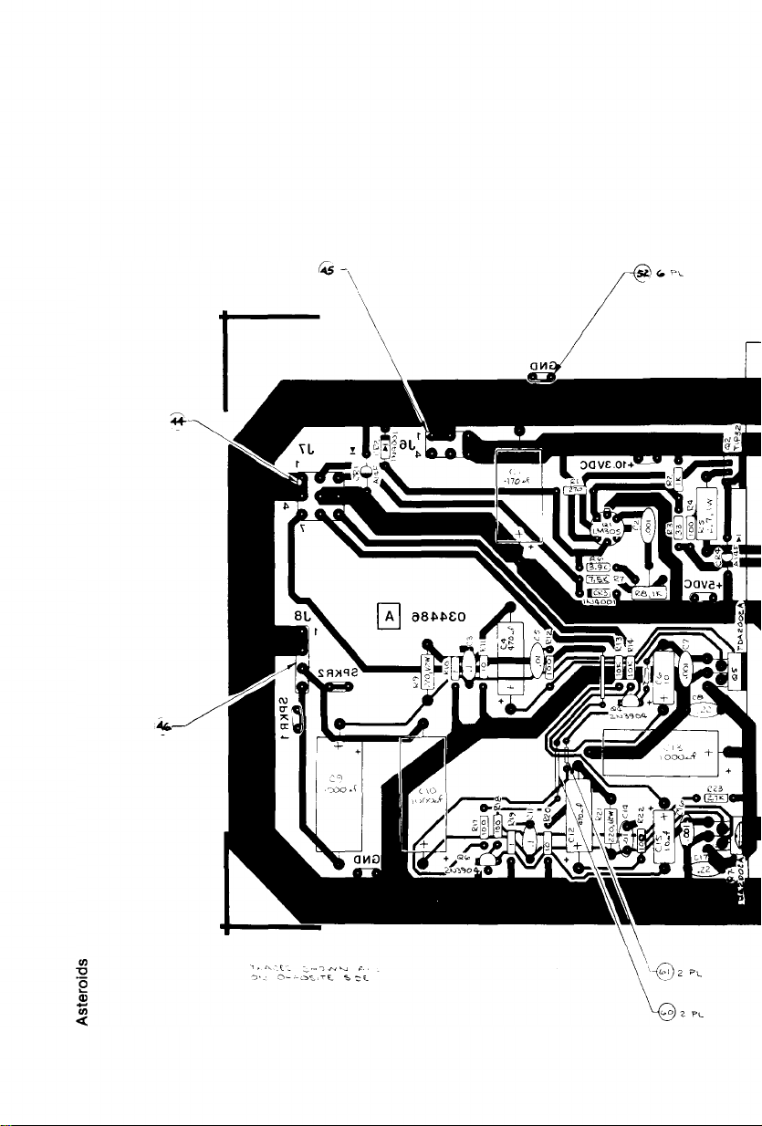
A03498 6-01 and -02 F
Fi gur e 16 Asteroid s Game PCB Assembly
_ _ IP iv J S T ^ \ _ U K l G » 7 4 L S 2 4 - 5
r J5 jojpp o □
| [T99 9 9 Ο o op_op "j
[ ^ W p ο o q p jf o o 'u 1
iPQQl^cTooooo ,
P O = m O M £>> lP ivjS T A . U L I M 6 i Α Κ Λ β ^ Ο * *
Asteroids
-U 'a f c . I . e . V*0 => \ T \ 0 »vJ
L . ' — U*> e. I. e . P O ^ l T t O W
1— e . E . ’s » . u e . T v j o e . t c s ,
'T e t A "i A - , OVJL.Y I F
74 - U S n O ‘s iw P 4 .,H4 - ,J 4
Board is permanently marked -01 or -02 after
“A034986” , located between rows 10 & 1 1 (-01 for
PROM, -02 for ROM version).
CM
Page 29

Figure 16 Asteroids Game PC B Assembly
Parts List
Part No. Des c r i p t io n (Re ference De s ignati o n s a n d L o c atio ns in Bold)
Ast e ro i d s
10
12
13
14
15
16
17
18
20
21
22
23
24
25
26
27
28
29
30
33
11
2
3
4
5
6
7
8
9
100000-270
100 000-680
100000-121
100000-15 1
100000-33 1
100000-47 1
100000-68 1
100000-102
100000-271
100000-122
100000-222
100000-272
100000-332
100000-392
100000-472
100 000-562
100 000-682
100 000-103
100000-123
100 000-153
100 000-183
100 000-223
100 000-333
100 000-473
100000-563
100000-104
100000-224
100 000-274
100 000-393
27 Ohm, ± 5 % , 1AW Resistor
68 Ohm, ± 5% , 1AW Resistor
120 Ohm, ±5 % , WW Resistor
150 Ohm, ± 5% , 1AW Resistor
330 Ohm, ± 5 % , 1AW Resistor
470 Ohm, ± 5% , 1AW Resistor
680 Ohm, ± 5 % , V4 W Resistor
1K Ohm, ± 5 % , 1AW Resistor
270 Ohm, ± 5 % , 1AW Resistor
1.2K Ohm, ±5% , 1AW Resistor
2.2K Ohm, ±5 % , 1AW Resistor
2.7K Ohm, ±5 % , 1AW Resistor
3.3K Ohm, ±5 % , 1AW Resistor
3.9K Ohm, ± 5 % , 1A W Resistor
4.7K Ohm, ± 5 % , 1A W Resistor
5.6K Ohm, ±5 % , 1AW Resistor
6.8K Ohm, ± 5% , 1AW Resistor
10K Ohm, ±5 % , 1AW Resistor
103,110-1,116,122,130-1,135-6,138-9)
12KOhm, ± 5 % , 1AW Resistor (R43)
15K Ohm, ± 5 % , 'AW Resistor
18K Ohm, ± 5 % , 1AW Resistor
22K Ohm, ±5 % , 1/4 W Resistor
33K Ohm, ±5 % , 1AW Resistor
47K Ohm, ±5 %, 1AW Resistor
56K Ohm, ±5 % , Va \ N Resistor
100K Ohm, ±5 % , 1AW Resistor
220K Ohm, ± 5% , 1AW Resistor
270K Ohm, ± 5% ,
39K Ohm, ± 5 % , 1AW Resistor
1 /4 W Resistor
(R72)
(R71)
(R105,109)
(R55)
(R30, 31,115)
(R32, 87-99)
(R57, 61)
(R27, 29, 53, 73, 85, 86, 132, 134)
(R112-113)
(R35, 100)
(R36, 75, 117,123, 133, 141)
(R66)
(R56, 65, 74, 142)
(R39, 64,106-108)
(R37, 82,102, 137, 140, 144)
(R40, 62, 67)
(R 49,104, 128, 129)
(R9-26, 28, 33, 38, 54, 58-60, 63, 69, 70, 79,
(R68)
(R51, 146)
(R1-8, 34, 41, 45, 50)
(R52)
(R42, 44, 48, 76, 78, 83,114)
(R145)
(R46, 81, 84, 143)
(R47)
(R101)
(R77)
34
35
39
40
41
44
45
46
47
49
50
51
53
54
55
56
57
58
61
63
66
67
19-007
19-3 15103
21-1 01104
21-1 01224
21-1 01473
24-250105
24-250107
24-2 50477
24-250226
27-2 50102
27-2 50103
27-250104
28-1 01100
28-101 680
28-101101
28-101221
28-101271
28-101391
29-006
29-046
31-1N914
31-1N4001
10K Ohm, 8-Pin Resistor Network. Use with the LS170 only, item 120. (RP1, 2)
10K Ohm Vertical PCB-Mounting Cermet Trimpot, Bournes Series
3352V-1-10K (R120, 126)
.1 uf, ± 10%, Radial-Lead Epoxy-Dipped 100V Mylar Capacitor (C64, 67-69)
.22 uf, ±10% , Radial-Lead Epoxy-Dipped 100V Mylar Capacitor (C33)
.047 uf, ± 10%, Radial-Lead Epoxy-Dipped 100V Mylar Capacitor (C46)
1.0 uf Aluminum Electrolytic Fixed Axial-Lead 25V Capacitor (C25, 70, 90, 92,
93)
100 uf Aluminum Electrolytic Fixed Axial-Lead 25V Capacitor (C19)
470 uf Aluminum Electrolytic Fixed Axial-Lead 25V Capacitor (C86, 87)
22 uf Aluminum Electrolytic Fixed Axial-Lead 25V Capacitor (C117)
.001 uf Ceramic-Disc 25V Radial-Lead Capacitor (C56)
.01 uf Ceramic-Disc 25V Radial-Lead Capacitor (C27, 32, 36, 40, 55, 58)
.1 uf Ceramic-Disc 25V Radial-Lead Capacitor (C1-18, 20-23, 26, 28-31, 34, 37,
41-44, 49, 51-54, 57, 60, 61, 63, 65, 66, 71-85, 91, 94-96, 99-100, 103-104,
107-108, 111-112, 114-116, 120-123)
10 pf Radial-Lead Epoxy-Dipped 100V Mica Capacitor
68 pf Radial-Lead Epoxy-Dipped 100V Mica Capacitor
100 pf Radial-Lead Epoxy-Dipped 100V Mica Capacitor
220 pf Radial-Lead Epoxy-Dipped 100V Mica Capacitor
270 pf Radial-Lead Epoxy-Dipped 100V Mica Capacitor
390 pf Radial-Lead Epoxy-Dipped 100V Mica Capacitor
1.0 uf, ± 10%, 35V Tantalum Capacitor (C24, 35, 47, 50, 62,113)
10 uf, ± 10%, 20V Tantalum Capacitor (C38, 39, 45, 48)
75V 1N914 Switching Diode (CR1-4, 6-8,15)
50V 1N4001 Silicon Rectifier Diode (CR9-12)
(C 97,105)
(C102,110)
(C89)
(C 98,106,118-119)
(C59)
(C88)
25
Page 30

Ast e r o ids
Figure 16 Asteroids Game PCB Assembly, continued
Parts List
Ite m
68
71
72
73
74
75
78
79
80
81
82
83
84
85
86
87
88
89
91
92
93
94
95
97
98
99
101
102
103
104
105
106
107
108
110
111
112
113
114
116
117
118
119
120
121
122
124
125
127
128
129
130
Pa r t No.
31-1N756A
33-2 N3906
34-2 N3643
34-2 N 3904
34-2N6044
34-MPSA06S
37-74LS00
37-74LS02 Type 74LS02 Integrated Circuit (D6)
37-7 404
37-74LS04 Type 74LS04 Integrated Circuit (B5, L5)
37-7406
37-74LS08
37-74LS10 Type 74LS10 Integrated Circuit (A8)
37-74LS14 Type 74LS14 Integrated Circuit (B6)
37-74LS20 Type 74LS20 Integrated Circuit (E5)
37-74LS32 Type 74LS32 Integrated Circuit (M5, N6, B9)
37-74LS42
37-74LS74 Type 74LS74 Integrated Circuit (D4, A7, R8)
37-74LS83
37-74LS86
37-7 497
37-74LS109
37-74LS139 Type 74LS139 Integrated Circuit (L3, E4)
37-74LS157 Type 74LS157 Integrated Circuit (F3, H3, J3, K3, F6, A10, B/C10, F/H10, C10,
37-74LS161
37-74LS164
37-74LS174 Type 74LS174 Integrated Circuit (N7, P7, D8, N11, F10)
37-74LS175
37-74191
37-74LS191
37-74LS193
37-74LS244 Type 74LS244 Integrated Circuit (B2, C2)
37-74LS245
OR
37-8304B
37-74LS251
37-74LS253
37-74LS259
37-74LS273
37-74LS367 Type 74LS367 Integrated Circuit (H6, J6)
37-74LS393
37-74LS374
OR
37-74LS273
37-74LS670
OR
37-74LS170
37-9316 Type 9316 Integrated Circuit (C4)
37-LM324 Type LM324 Integrated Circuit (L8, P11)
37-555
37-566
37-4016B Type 4016B Integrated Circuit (M9, N10, R11, B12, D12)
37-TL082CP
37-AD561J
137108-001
D es cr i pt i on (Refere n ce D esign ati ons and Loc atio ns in Bo ld)
8.2V, ± 5%, 1N756A Zener Diode (CR 13,14)
Type 2N3906 PNP Switching and Amplifying Transistor (Q1-5, 7,10,16-17)
Type 2N3643 NPN Silicon Transistor (Q6)
Type 2N3904 NPN 60V 1-Watt Transistor (Q8, 9)
Type 2N6044 Darlington NPN Transistor (Q11-13)
Type MPSA06S NPN 80V 500ma Transistor (Q14,15)
Type 74LS00 Integrated Circuit (N5, C6)
Type 7404 Integrated Circuit (H10)
Type 7406 Integrated Circuit (N9)
Type 74LS08 Integrated Circuit (E6, K6, R7, B8)
Type 74LS42 Integrated Circuit (L6, E7, E8)
Type 74LS83 Integrated Circuit (M6)
Type 74LS86 Integrated Circuit (P5)
Type 7497 Integrated Circuit (F8, H8, J8, K8)
Type 74LS109 Integrated Circuit (A9)
D/E10, E10)
Type 74LS161 Integrated Circuit (C5, P8, B7, C7, D7)
Type 74LS164 Integrated Circuit (K9, P9, R9)
Type 74LS175 Integrated Circuit (M7)
Type 741 91 Integrated Circuit (C4)
Type 74LS191 Integrated Circuit (K5, C9, D9, E9, F9, H9, J9)
Type 74LS193 Integrated Circuit (F5, H5, J5)
Type 74LS245 Integrated Circuit (R2, E3)
Type 8304B Integrated Circuit— substitute for item 107 (P2, E3)
Type 74LS251 Integrated Circuit (J10, L10)
Type 74LS253 Integrated Circuit (P6)
Type 74LS259 Integrated Circuit (M10)
Type 74LS273 Integrated Circuit (F7, H7, J7, K7)
Type 74LS393 Integrated Circuit (B4, D5)
Type 74LS374 Integrated Circuit (B10, D10)
Type 74LS273 Integrated Circuit— substitute for item 11 7
Type 74LS670 Integrated Circuit (F4, H4, J4)
Type 74LS170 Integrated Circuit— substitute for item 119
Type 555 Timer Integrated Circuit (M8, N8, L9, R10)
Type 566 Function Generator Integrated Circuit (P10)
Type TL082CP Integrated Circuit (A12, C12)
Type AD561J Integrated Circuit (B11, D11)
Operational Amplifier Integrated Circuit (B/C12, E12)
26
Page 31

Figure 16 Asteroids Game PC B Assembly, continued
Parts List
Part No. D esc r ip t i o n (Re ference De s igna ti o n s and Lo c atio n s in Bold)
Ast er o id s
132
133
134
135
137
139
141
142
143
144
146
148
150
151
152
155
157
159
159
37-7805
37-7812
37-7815
37-7915
38-MV5053
41-3 003
62-001
66-118P1T
66-114P1T 4-Station Single-Throw, Dual-lnline-Package Bit Switch (M12)
79-42C40 40-Contact Medium-lnsertion-Force Integrated Circuit Socket (C3)
81-4302
02 0670-01 Test Point
90-102
90-601 3
90-703 3
034602-01
035127-01
035129-01
035130-01 Programmable Read-Only Memory, LSB— substitute for half of item 157
F or remaining memory compon ent s and thei r part num ber s ,
+ 5V Voltage Regulator
+ 12V Voltage Regulator
+ 15V Voltage Regulator
- 15V Voltage Regulator
Type MV5053 Light-Emitting Diode (CR5)
100 uH, ±5 % , Hot-Molded Plastic Fixed R.F. Choke (L1-13)
SPST Pushbutton Switch (A6)
8-Station Single-Throw, Dual-lnline-Package Bit Switch (R6)
Nylon Snap-In Fastener
12.0 96 MHz, ±.005%, Crystal (Y1)
Microprocessor (C3)
Random-Access Memory (D2, E2, M4, N4, P4, R4)
Programmable Read-Only Memory (C8)
Read-Only Memory (N/P3)
OR TH E FOLLOW ING TW O ITEMS:
Programmable Read-Only Memory, MSB— substitute for half of item 1 57
see listing belo w.
Me mo ry C o m p on e n ts and Their Equivalents
(Location s Sho wn in Bold)
(K4)
(L4)
-01 P.C. Boards Alternate -01 P.C. Boards -02 P.C. Boards
(PROMs)
035131-01 J2
035132-01 N2
035137-01 K1
035138-01 N1
035133-01 H2
035134-01 M2
035139-01 J1
035140-01 M1
035135-01 F2
035136-01 L2
035141-01 H1
035142-01 L1
(PROMs)
035150-01 J2
035153-01 K1
035151-01 H2
035154-01 J1
035152-01 F2
035155-01 H1
(ROM s)
035143-01 C1
035144-01 D/E1
035145-01 F1
27
Page 32
Page 33

NO T I C E TO A L L PE R S O N S R E C E I V IN G TH IS D R A W I N G
CO N F I D E N T I A L Re p r o d u c t i o n forb idd en w i t h o u t the
sp e c i f i c w r i t te n per m i s s i o n o* At a r i . Inc Su n n y v a l e .
Ca li f o r n i a Thi s d r a w i n g is o n ly c o n d i t i o n a l l y i s s u e d , an d
ne i th e r r e c e i p t n o r p o s s e s s io n t h e re o f c o n f e rs or t r a n s fe rs
an y r i g h t m. or lice n s e to u s e th e s u b t e c t m a t t e r o f th e
dr a w i n g or an y d e s ig n o ' te c h n i c a l in f o r m a t i o n sh o w n
the re o n , n o r a n y ri g h t t o r e p r o d u c e th is d r a w in g o r a ny p a r t
the re o f, e x c e p t f o r m a n u fa c t u r e by ve n d o r s o f A t a r i. I n c o r
po r a te d a n d for m an u fa c tu r e u n d e r t h e c o r p o r a t i o n s wr i t
ten li c e n s e , n o ng h t to re p r o d u c e th i s d r a w in g is gr a n t e d
or th e s u b je c t m at ter th e r e o f u n le s s b y w r i t t e n ag ree me nt
wi t h or w r i t t e n pe r m i s s i o n Ir o m th e co r p o r a t i o n
A03 4485-01 D
Figur e 17 Re gulator / Audio PCB Assembly
Page 34

Figure 17 Regulator/Audio PCB Assembly
Parts List
Part No. Qty. De sc ripti on (Ref. Design ati on s in B old )
Ast e ro i d s
10
11
13
15
16
1 7
20
22
23
25
26
27
29
31
32
34
35
36
38
39
44
45
46
47
48
49
50
51
52
53
57
58
60
61
2
3
4
5
6
7
8
9
110000-010
110000-100
110 000-330
110000-10 1
110000 -27 1
110000-102
110000-272 1
110000-752
110000-103
110000-392 1
110001-22 1
12-52P7
19-100P1015
19-315102
24-2 50106
24-2 50477
24-250108
27-2 50103
27-2 50104
27-2 50224
27-250102
31-A14F
31-1N4001
33-TIP32
34-2 N3055
34-2 N3904
37-LM305
37-TDA2002A 2 Type TDA2002A 8W Linear Audio Amplifier Integrated Circuit (Q5, 7)
79-58008
79-58092
79-58059
79-20230
034531-01
72-1608C
75-99516
75-056
02 0670-01
75-F60805
78-16008
78-16014
52-003
52-004
2
2
1 33 Ohm, ± 5%, VaW Resistor (R3)
5 100 Ohm, ± 5%, V4W Resistor (R 4 ,12,17,18, 22)
1 270 Ohm, ± 5% , 1/4 W Resistor (R1)
1
1 7.5K Ohm, ± 5%, 1 /4 W Resistor (R7)
2 10K Ohm, ± 5% , 1 /4 W Resistor (R13,14)
2 220 Ohm, ± 5%, 1 /2W Resistor (R9, 21)
1 2.7 Ohm, ± 5%, 1W Resistor (R5)
1
1 1K Ohm Vertical PCB-Mounting Cermet Trimpot, Bournes Series 3352V-
2 10 uf Aluminum Electrolytic Fixed Axial-Lead 25V Capacitor (C6 ,15)
3 470 uf Aluminum Electrolytic Fixed Axial-Lead 25V Capacitor (C l, 4,
3
2
2 .1 uf Ceram ic-Disc 25V Radial-Lead Capacitor (C3, C11)
2 .22 uf Ceramic-Disc 25V Radial-Lead Capacitor (C 8 ,17)
3 .001 uf Ceramic-Disc 25V Radial-Lead Capacitor (C2, 7,16)
2 50V 2.5A Miniature Axial-Lead High-Current Rectifier (CR1, CR4)
2 50V Silicon Rectifier 1N400 1 Diode (CR2-3)
1 PNP Power Transistor, Type TIP32 (Q2)
1 NPN Silicon Transistor, Type 2N3055 Q3)
2 NPN Silicon Transistor, Type 2N3904 (Q4, 6)
1
1 9-Position Connector Receptacle (J7)
1 6-Position Connector Receptacle (J6)
1 4-Position Connector Receptacle (J8)
19
1 Heat Sink
4
7 #6-32 Nut/Washer Assembly
7
6 Test Point
3
1
3
2 Teflon-Insulated Solder-Plated Solid Copper PCB-Mounting Jumper Wire
2 Teflon-Insulated Solder-Plated Solid Copper PCB-Mounting Jumper Wire
1 Ohm, ± 5% , 1AW Resistor (R10,19)
10 Ohm, ± 5% , 1 /4 W Resistor (R11, 20)
1K Ohm, ± 5%, 1 /4 W Resistor (R2)
2.7K Ohm, ± 5%, 1/4 W Resistor (R23)
3.9K Ohm, ± 5%, 1 /4 W Resistor (R6)
.1 Ohm, ± 3%, 7W Wirewound Resistor (R24)
1-1K (R8)
12)
100 uf Aluminum Electrolytic Fixed Axial-Lead 25V Capacitor (C9 ,10,
13)
.01 uf Ceramic-Disc 25V Radial-Lead Capacitor (C5, C14)
5V Linear Voltage Regulator (Q1)
Female PCB-Mounting Terminal
#6-32 x 1/2” Cross-Recessed Pan-Head Corrosion-Resistant Steel
Machine Screw
#6 Internal-Tooth Steel Lock Washer
#6-32 x 1 /2” Binder-Head Nylon Screw
Thermally Conductive Compound for the 2N3055
Thermally Conductive Compound for TDA2002A and TIP32
with .6” Centers
with .3” Centers
29
Page 35

Ast e r o ids
TOP VIEW
NOTE:
The four available voltage selection plugs are listed in
Figure 14, Final Assembly.
NO T IC E T O AL L PE R S O N S R E C E IV IN G T H I S DR A W I N G
CO N F I D E N T I A L : Re p r o d u c t io n for b id d e n wi t h o u t the
sp e c i f i c w ri t t e n p e r m i s s io n o f At a r i, In c.. S u n n y v a l e .
Ca l i fo rn ia . T h i s dr a w i n g is on ly c o n d i t i o n a l l y is s u ed , and
ne it h e r r e c e ip t n o r p o s s e s s i o n t h e r e o f c o n f e rs o r t r a n sf e rs
any r i g h t m. o r l ic e n s e to us e . th e s u b je c t m a t t e r o f the
dr a w i n g or an y de s i g n or te c h n i c a l in fo r m a t i o n sh o w n
the re o n , n o r a n y r ig h t t o r e p r o d u c e t h is d ra w i n g o r a n y pa rt
th e r e o f , e x c e p t fo r m a n u f a c t u r e by v e n d o r s o f A ta r i. I n c o r
po r a t e d a n d fo r m an u f a c t u r e un d e r t h e c o r p o r a t i o n s w ri t
ten li c e n s e , no rig h t to r e p r o d u c e t h i s d ra w in g is g ra n te d
or th e s u b je c t m at t e r th e r e o f un l e s s b y w ri t t e n a g r e e m e n t
wi t h o r w ri t t e n pe r m is s i o n fro m t h e co r p o r a t i o n
BOTTOM VIEW
30
Figure 18 Power Supply Assembly for X-Y Games
A0 3 4 5 6 1 - 0 1 D
Page 36

Figure 18 Power Supply Assembly for X-Y Games
Parts List
Aste r oi d s
Item
A
1
2
3
4
5
6
7 78-70501 SC
8
9
10
11
12
13
14 72-HA4606S
15
16
17 75-99518
B
C
D
E
F
G
H
Pa r t No.
A034 955-01
034482-01
79-4411006
79-3206
46-2017002
46-2013002
29-053
79-15021001
78-2708
A006555-01
72-HA4804S
72-HA4812S
72-1008F
75-01 OS
75-01 8S
A034 630-01
A034 629-01 2
A034623-02
034544-01
75-01 8S
75-99518
72-HA4812S
Qty.
1
1
1
1
3 7-Amp. 250V 3AG Slow-Blow Glass Cartridge-Type Fuse
3 3-Amp. 250V 3AG Slow-Blow Glass Cartridge-Type Fuse
1
1 2" Diameter Capacitor Mounting Bracket
1 2-Circuit Single-Row Terminal Block
1
1
3
1
2 #10-32 x V i" Cross-Recessed Pan-Head Zinc-Plated Steel Thread-Rolling
4
2 #10 Flat Plain SAE-Standard Zinc-Plated Steel Washer
4
1 #8-32 Nut/Washer Assembly
1
1
1 Fuse Block Cover
4 #8 Flat Plain SAE-Standard Zinc-Plated Steel Washer
6
2 #8-32 x 314" Cross-Recessed Pan-Head Zinc-Plated Steel Thread-Rolling
D es cr i pt ion
Power Supply Sub-Assembly, Rev. A, consisting of the following 17 items:
Base for Power Supply Chassis
Panel-Mounting Non-Indicating 3AG Cartridge-Type Fuse Post
5-Position 3AG Fuse Block with 1A " Quick-Disconnect Terminals
26,000 uf 15V Electrolytic Capacitor
Nylon Type 6/6 Hole Bushing with 5/8” Inside Diameter x 55/64” Outside
Diameter x 1A " Thick
Rectifier Printed Circuit Board Assembly
#8-32 x 1A" Cross-Recessed Pan-Head Zinc-Plated Steel Thread-Rolling
Tri-Fluted “Taptite” Screw
#8-32 x V*" Cross-Recessed Pan-Head Zinc-Plated Steel Thread-Rolling
Tri-Fluted “Taptite” Screw
Tri-Fluted “Taptite” Screw
#6-32 x 3/ 8" Cross-Recessed Pan-Head Zinc-Plated Steel Thread-Rolling
Tri-Fluted “Taptite” Screw
#8 Flat Plain SAE-Standard Zinc-Plated Steel Washer
RFI Filter Assembly
A.C. Harness Assem bly
Power Supply Harness Assembly (for X-Y Games)
#8-32 Nut/Washer Assembly
Tri-Fluted “Taptite” Screw
31
Page 37

Ast er o id s
NO T I C E TO A L L P E R S O N S RE C E IV IN G T H I S DR A W I N G
CO N F I D E N T IA L R e p r o d u c ti o n forb id d e n wi t h o u t the
sp e c i fi c w r i t te n per m i s s io n of At a r i. In c . S u nn y v a le ,
Ca l if o r n i a . Th i s dr a w i n g is on l y co n d i t i o n a l l y iss u e d , and
ne i th e r re c e ip t no r p o s s e s s io n th e r e o f c o n fe rs or t r a n s f e r s
any r ig h t in. o r li c e n s e to us e. the s u b je c t m at t e r o f th e
dr a w i n g or any d e s i g n or te c h n ic al i n f o rm a ti o n sh o w n
the r e o n , no r a n y ri g h t to r e p r o d u c e th i s d ra w i n g or a n y part
the r e o f, e x c e p t f o r m a n u fa c t u re b y v e n d o r s o f A t a ri . In c o r
po r a te d a n d f o r m a n u fa c t u re u n d e r t h e c o r p o r a t i o n 's w r i t
ten li c e n s e , no r i g h t to re p ro d u c e th is dr a w in g is gr a n t e d
or th e s u b je c t m a t t e r th e r e o f u n le s s by wr i t t e n a g r e e m e n t
w it h or w r i t t e n pe r m is s io n fro m th e co rp o r a ti o n
Item
1
2
3
4
5
— E>N & BN
Figure 19 Main Harness and Component Assembly
A035158-02 A
Part No.
A035157-01
A034631-01
68-002
000268-02
A030169-01
Descr i pti on
Main Harness Assembly
On/Off Switch Assembly
Interlock Sw itch (2 per game)
Interlock Sw itch Mounting Bracket
Volume Control/Test Switch/Bracket Assem bly
- 0 2 O N LY
32
Page 38

Ast er o id s
NO T I C E T O A L L P E R S O N S RE C E I V I N G TH IS DR A W I N G
CO N F ID E N T I A L : Re p ro d u c t io n for b i d d e n w i t h o u t the
sp e c i fi c w ri t te n p e r m i s s io n of At a ri . Inc., S u n n yv a l e ,
Ca li fo r n i a T h i s d r a w in g is o n l y co n d i ti o n a l ly is s u e d , and
ne it h e r r e c e ip t no r p o s s e s s i o n th e re o f c o n fe rs or t ra ns fe r s
any r ig h t in. o r lice n s e to us e . th e s u b je c t m a t t e r of th e
dr a w in g or any de s ig n or tec h n i c a l in fo r m a t io n s h o w n
the r e o n , n o r a n y r i g h t t o r ep ro d u c e t h i s d ra w i n g o r a n y part
the re o f, e x c e p t fo r m a n u f a c tu r e by v e n do rs o f A ta ri, Incor ·
Figure 20 Fluorescent Light Assembly
A034752-01 A
Item
Par t No .
1 A005493-01 Fluorescent Light Harness
13 93-113 18” Fluorescent Lamp Fixture with Starter
14 79-561816 Spring Connector Wire Nut for 16- to 18-Guage Wires
15
78-2652
Descr i pti on
Rubber Grommet with 5/8” Inside Diameter x 1 1/8” Outside Diameter x 5/16”
Thick — for 7/8 ” Diameter Sheet-Metal Holes
r*-A
I
■— A
33
Page 39

Ast e ro i d s
21) 2 PLCS
15} 2 PLCS
9 ) 2 PLCS
NO T IC E TO A L L PE R S O N S R E C E IV IN G T H I S D R A W I N G
CO N F ID E N T I A L ; R e p ro d u c t i o n for b id d e n w i t h o u t the
sp e c i f i c w r i tt e n per m i s s i o n of At a r i, I n c., S u n n y v a l e,
Ca l if o r n i a . T h is d r a w i n g is on ly c o n d i t i o n a l l y is s u e d , an d
ne i t h e r r e c e i p t n o r p o s s e s s i o n t h e r e o f c o n f e rs o r t r a n s f e rs
any r ig h t in, or li c e n s e to us e, the s u b j e c t m a tt e r o f th e
dr a w i n g or an y de s i g n or tec h n ic a l in f o r m a t i o n s h o w n
the r e o n , n o r a n y r ig h t t o r e p ro d u c e t h i s d r a w i n g o r a n y p ar t
the re o f, e x c e p t f o r m an u f a c t u r e by v e n d o r s o f A t a r i, I n c o r
po r a t e d a n d fo r m a n u fa c t u re u n d e r th e c o r p o r a t i o n ' s w r i t
ten li c e n s e , n o r i g h t to re p ro d u c e t h is d r a w i n g is g r a n t e d
or t h e s u b je c t m a t t e r t h e r e o f u n le s s b y w ri t t e n a g re e m e n t
wi t h or w ri t t e n pe r m i s s io n fro m the c o r p o r a t o r
34
Figure 21 Coin Door Assembly
A006794-1 6 thru -28 K
Page 40

Figure 21 Coin Door Assembly
Parts List
Ast e ro i d s
10
11
12
13
15
16
17
18
20
21
22
23
24
25
26
27
28
30
32
33
34
Part No.
1
2
3
4
5
6
8
9
A007637-16
A007637-17
A007637-18
A007637-19
A007637-20
A007637-21
A007637-22
A007637-23
A007637-24
A007637-25
A007637-26
A007637-27
A007637-28
72-HA4608C
A030362-01
A030250-01
A002465-01
004320-01
004344-01
004340-01
004337-01
004338-01
004336-01
004326-01
006904-01
030257-01
70-11-47
73-3008
72-HA4604C
75-99516
008629-01
71-2118
71-1225CU
71-1205FF
71-1201 MG
71-1201KS
71-12100YJ
71-1210PE
71-1220CA
71-1202MG
71-1201FF
71-1201BT
71-1205MG
71-12100LI
71-1201ADU
007753- 01
A007638-01
75-036S
73-3025
75-056
033368-01
033369-01
033371-01
Qty.
» Front Bezel Assy.— Used only on -16 Coin Door Assy. (25<t)
t Front Bezel A ssy.— Used only on -17 Coin Door Assy. (5 Fr)
O
CD
O ~
2.3
3 CD
O c
- i CO
CD
Q .
F or br eakdown of Front Be z el As sy . , see Fi gure 22
3 #6-32 x V2” Cross-R ecessed Pan-Head Cadmium-Plated Steel Tri-
1
2
1
1
1
2
2
1
1
2
2
1
1
2
2
13*
2
1
to
o
t°
Ό 0)
0) <D D
(/) ~* 'C
^ Ο Λ
CD o 2»
-3 5" CD
Φ Ο ω
ο . Ο CD
c
0)
CD
Q .
I
1
1
4
6
Des cr i pti on
Front Bezel Assy .— Used only on -18 Coin Door Assy. ( 1 DM)
Front Bezel A ssy.— Used only on -19 Coin Door Assy. (1 Kr)
Front Bezel Assy.— Used only on -20 Coin Door Assy. (100 Y)
Front Bezel A ssy .— Used only on -21 Coin Door A ssy. (10 pence)
Front Bezel Assy.— Used only on -22 Coin Door Assy. (20<t
Australian)
Front Bezel A ssy.— Used only on -23 Coin Door Assy. (2 DM/1 DM)
Front Bezel Assy .— Used only on -24 Coin Door A ssy. (1 Fr)
Front Bezel A ssy .— Used only on -25 Coin Door Assy. (1 Baht)
Front Bezel Assy.— Used only on -26 Coin Door Assy. (1 DM/5 DM)
Front Bezel Assy .— Used only on -27 Coin Door Assy. (100 Lire)
Front Bezel Assy.— Used only on -28 Coin Door Assy. (2 5 «yU.S. $1
coin)
Fluted Thread-Rolling Screw
Coin Lockout Assem bly
Coin Sw itch Assem bly
Coin Counter Assem bly
Coin Door Weldment
Key Loop
Spring Return (used only on German DM coin doors)
Bracket for Lock-Out Wires
Right-Hand Lock-Out Wire
Left-Hand Lock-Out Wire
Scavenger Button
Spacer (used only on German DM coin doors)
Lamp Socket
NEMA #47 Incandescent Miniature Bayonet-Base Lamp
Carbon Spring Steel External Retaining Ring, for V a " Diameter Shaft
#6-32 x 1A ” Cross-Recessed Pan-Head Cadmium-Plated Steel Tri-
Fluted Thread-Rolling Screw
#6-32 Steel Nut and Spring Washer Assem bly
'Q uantity of 15 is used on the German DM coin doors
Spring
Cam Lock, Hudson #CR73A045S
Coin Mechanism for American Quarter
Coin Mechanism for French 5-Francs Coin
Coin Mechanism for German 1-Mark Coin
Coin Mechanism for Swedish 1-Krona Coin
Coin Mechanism for Japanese 100-Yen Coin
Coin Mechanism for English 10-Pence Coin
Coin Mechanism for Australian 20-Cent Coin
Coin Mechanism for German 2-Mark Coin
Coin Mechanism for French 1-Franc Coin
Coin Mechanism for Thai 1-Baht Coin
Coin Mechanism for German 5-Mark Coin
Coin Mechanism for Italian 100-Lire Coin
Coin Mechanism for U.S. $1.00 Coin
Anti-Probe Plate
Slam Switch Assem bly
#6 Flat Plain SAE-Standard Zinc-Plated Steel Washer
Carbon Spring Steel External Retaining Ring, for 0.184" Diameter
Shaft
#6 Internal-Tooth Zinc-Plated Steel Lock W asher
Lock Bracket
Lock Arm
Slam Switch Insulator
35
Page 41

Ast e ro i d s
Item
1
2
3
4
5
6
7
7
8
9
10
11
13
x ' S ' v
ΙΘ θ)
O L——
Par t No.
004328-02
004330-02
004330-02
009153-02
004330-02
009153-02
007752-02
007752-02
030677-02
009153-02
030677-02
007752-02
030677-02
004331-02
004332-02
004327- 01
004329- 01
004343- 01
004343-06
004343-04
004343-03
004343-05
004343-02
004343-07
004343-08
004343-09
004343-10
004343-11
004343-12
004343-13
73-3009
72-1604S
75-046
72-CL606 6
75-056
6 PLCS
/
A
NOTIC E TO A L L P ERS O NS R EC EIV ING TH IS D RA W ING
CO N FID E N TIA L Rep ro d uc tio n forbid de n witho ut the
spec if ic w ritt en per m iss io n of Atari. Inc , Su nny vale,
Cali forn ia T his d ra win g is o nly c on di tio na ll y issued, and
neith er r ece ipt nor po ss es si on ther eo f co nf er s or tra nsfe rs
any right in. or li cen se to use. th e sub jec t ma tte r o f the
draw in g or an y d es ig n or tec hn ica l in fo rm ati on show n
thereo n, nor any right to r ep ro du ce t his d ra wi ng or any part
there of, ex ce pt for m a nu fac tu re by v end or s of Atari, inc o r
pora ted and for m a nu fa ctu re un der the co rpo ra tio n's w rit
ten lice nse, no rig ht to re pr od uc e th is dr aw in g is gra nted
or the sub je ct matt er th ere of u nl ess by w rit ten a gre eme nt
with or w ritt en pe rm iss ion from th e c orp ora tio n
3 ; 2 PLCS
i® ©1
h 4
J © U
&
Fi g u r e 22 Fro nt B ezel Asse m bly
A007637- 16 thr u -28 J
Parts List
Qty.
1 Bezel
i
$
*S 0 Ring for Swedish 1-Krona Coin
-» 0
0
2 .3
3 CD
λ w
CD
a
1
2
2
2
2 Price Plate Clamp
*
t
0
"O CD
CD A
O
2 .3
3 CD
( j )
θ" CD
0 C
^ c/>
CD
f
2 Carbon Spring Steel External Retaining Ring, for 3/8” Shaft Diameter
3
2
1
Descr i pti on
Ring for American Quarter
Ring for French 5-Franc Coin
Ring for German 1-Deutschmark Coin
Ring for Japanese 100-Yen Coin
Ring for English 10-Pence Coin
Ring for Australian 20 Coin
Ring for German 2-Deutschmark and U.S. $1.00 Coins
Ring for French 1-Franc Coin
Ring for Thai 1-Baht Coin
Ring for German 5-Deutschmark Coin
Ring for Italian 100-Lire Coin
Coin Shield
Primary Coin Chute
Scavenger Button Bearing
Price Plate— 25Φ
Price Plate— 5 F R
Price Plate— 7 DM
Price Plate— 7 K R
Price Plate— V 100
Price Plate— 10 P
Price Plate— 20Φ Austral i an
Price Plate— Einwurf 2 DM11 DM
Price Plate— 7 F R
Price Plate— 7 Baht
Price Plate— Einwurf 1 DM/5 DM
Price Plate— 700 Lir e
Price Plate— 25$/$1
#6-32 x 1A ” Cross-Recessed Pan-Head Cadm ium-Plated Steel
Machine Screw
#6 Corrosion-Resistant Steel Split Lock Washer
#6-32 x 3/8” Phillips Pan-Head Steel “ Rolok” Self-Threading,
Thread-Rolling Machine Screw
#6 Internal-Tooth Zinc-Plated Steel Lock Washer
2 PLCS
36
Page 42

Asteroids
NO T I C E T O A L L P E R S O N S R E C E IV IN G T H IS D R A W I N G
CO N F I D E N T I A L : Re p ro d u c t i o n for b id d e n wit h o u t the
sp e c i f i c w r i t te n per m i s s io n o f Ata r i , In c ., Su n n y v a l e ,
Ca li fo rn ia . Th is dr a w i n g is o n l y co n d it i o n a l l y is s u e d , and
ne i t h e r r e c e i p t n o r p o s s e s s io n t h e r e o f c o n f e r s o r tr a n s f e rs
any ri g h t in , o r lic e n s e t o use , th e s u b j e c t m a tt e r of th e
dr a w i n g or a n y de s i g n or te c h n i c a l in f o r m a t i o n sh o w n
the r e o n , n o r an y ri g h t t o r e p r o d u c e t h is d r a w i n g o r a n y p a rt
the re o f , e x c e p t f o r m a n u f a c t u re b y v e n d o r s o f A t a r i, In c o r
po r a t e d a n d f o r m a n u f a c t u re u n d e r th e c o r p o r a ti o n 's w ri t
ten li c e n s e , no r i g h t t o r e p r o d u c e t h i s d r a w in g is g r a n te d
or t h e s u b je c t m a t t e r t h e r e o f u n le s s b y w r i t t e n a g re e m e n t
w it h o r w r i t t e n p e r m i s s io n fr o m th e c o r p o r a t i o n
75-1408S
COIN INLET
CHUTE
99-10071
99-10096
99-10103
75-948S
99-10095
PART OF 99-10095
COIN MECHANISM
SEE PARTS LIST
(71-12xxxx)
COIN RETURN
CHUTE
38
COIN SWITCH ASSY.
SEE PARTS LIST
(99-10042 thru
99-10045)
31-1N4002
PART OF 99-10047
99-10082
75-1412S
Figure 23 New Coin Do o r
71-1 0 xx x x
Page 43

COIN RETURN BUTTON ASSY .
SEE PARTS LIST
(99-10012 thru 99-10022)
COIN DOOR ONLY
SEE PARTS LIST
(99-10009 thru 99-10010)
99-10094
PART OF
REJECT BUTTON COVER
SEE PARTS LIST (99-10055 thru 99-10059)
PRICE PLATE
SEE PARTS LIST
(99-10070, 99-10083
thru 99-10092)
99-10062
Asteroids
72-JA1405B
99-10054
72-HA1404C
99-10049
NO T I C E T O A L L P E R S O N S R E C E IV I N G T H IS D R A W I N G
CO N F ID E N T I A L : Re p ro d u c t i o n forb id d e n wit h o u t the
sp e c i f i c w r i tt e n p e r m is s io n o f Ata r i , Ip c ., Su nn yv a l e ,
Ca l if o r n i a . T h is d r a w in g is o n l y c o n d it i o n a l ly iss u e d , an d
ne it h e r r e c e i p t n o r p o s s e s s i o n t h e r e o f c o n f e r s or tr a n s fe rs
an y ri g h t in, o r lic e n s e to us e , th e s u b je c t m a t t e r of t h e
dr a w i n g or any de s ig n or te c h n ic a l i n fo r m a t i o n sh o w n
the r e o n , n o r an y r i g h t t o r ep ro d u c e t h is d r a w in g o r a n y p a rt
the r e o f , e x c e p t f o r m a n u fa c t u re b y v e n d o r s o f A t a ri , I n c o r
por a te d a n d fo r m an u f a c t u r e u n d e r th e c o r p o r a ti o n ' s w r i t
ten lic e n s e , no r i g h t t o re p r o d u c e th i s d r a w i n g is g r a nt e d
or t h e s u b je c t m a tt e r t h e r e o f u n l e s s b y w r i t t e n a g r e e m e n t
w i t h o r w r it t e n p e r m i s s i o n f r o m th e c o r p o r a t i o n .
99-10061
99-10066
75-915S
72-JA1405B
99-10051
Figure 23 New Coin Do o r
71-1 0 xx x x
39
Page 44

Asteroids
Figure 23 New Coin Do or , continued
Par ts List
Pa r t No.
31-1N4002
65-441C General-usage low-force miniature switch
70-11-47 Miniature bayonet-base incandescent lamp, type #47
71-1201ADU
71-1201FCH Swiss 1 Fr coin mechanism
71-1201 MG
71-1202MG
71-1205FB Belgian 5 Fr coin mechanism
71-1205MG
71-1210PE
71-1220CA
71-1225CU U.S. 25Φ coin mechanism
71-12100LI Italian 100 Lire coin mechanism
71-12100YJ Japanese Y100 coin mechanism
72-HA1404C
72-JA1405B
72-9406S
72-9603S #6-32x3/16” Slotted truss-head steel machine screw
75-915S #1 /4-20 Standard pattern cadmium-plated steel hex nut
75-918S
75-944S
75-948S
75-1408S
75-1412S #4-40x%” Slotted pan-head steel machine screw
75-5520B #1/4-20x11/4” Round-head square-neck steel bolt with black finish
D es cr i pti on
100V Silicon Rectifier 1N4002 Diode
U.S. $1.00 coin mechanism
German 1 DM coin mechanism
German 2 DM coin mechanism
German 5 DM coin mechanism
U.K. 10 P coin mechanism
Australian 20<t coin mechanism
# 4 x 1/4” Slotted pan-head thread-roiling tri-fluted “Taptite” cadmium-plated screw
#4x5/16” Slotted pan-head thread-rolling tri-fluted “ Plastite” black screw
#4-40x3/8” Slotted truss-head steel machine screw
#8-32 Standard pattern cadmium-plated steel hex nut
#4-40 Polymer self-locking steel hex nut
#8-32 Polymer self-locking steel hex nut
#4-40x 1/2” Slotted pan-head steel machine screw
99-10008
99-10009
99-10010
99 -10011
99-10012 U.S. 2 5<t coin return button assembly
99-10013 U.S. $1.00 coin return button assembly
99-10014
99-10015
99-10016
99-10017
99-10018
99-10019 Japanese Y100 coin return button assembly
99-10020
99-10021
99-10022 Italian 100 Lire coin return button assembly
Switch wire retainer
2-Mech coin door only
3-Mech coin door only
Inner panel
German 1 DM coin return button assembly
German 2 DM coin return button assembly
German 5 DM coin return button assembly
Belgian 5 Fr coin return button assembly
Swiss 1 Fr coin return button assembly
U.K. 10 P coin return button assembly
Australian 20$ coin return button assembly
40
Page 45

Figure 23 New Coin Do or , continued
Parts List
Asteroids
Pa r t No.
99-10 040
99-10041
99-10042
99-10 043
99-10044
99-10045
99-10047
99-10048
99-10049
99-10051
99-10054
99-10055
99-10056
99-1 0057
99-10058
99-10059
99-10061
99-10062
99-10063
99-10064
99-10065
99-10066
99-10070
99-10 071
D es cr i pti on
Coin inlet chute assembly
Coin counter assembly
Coin switch assembly for U.S. 2 5<t and Belgian 5 Fr coins (silver wire)
Coin switch assembly for German 1 DM, Swiss 1 Fr, and Japanese Y100 coins (black wire)
Coin switch assembly for U.S. $1.00, German 2 DM, and Italian 100 Lire coins (gold wire)
Coin switch assembly for German 5 DM, U.K. 10 P, and Australian 20$ coins (green
Lockout coil assembly
Coin door harness assembly
Locking arm assembly
Coin door frame
Coin button housing
Coin return button cover for Japanese Y100 coin
Coin return button cover for German 1 DM and Swiss 1 Fr coins
Coin return button cover for U.S. 25Φ and Belgian 5 Fr coins
Coin return button cover for U.S. $1.00, German 2 DM, and Italian 100 Lire coins
Coin return button cover for German 5 DM, U.K. 10 P, and Australian 20Φ coins
Coin return bezel
Coin return button
Right half of coin inlet chute
Left half of coin inlet chute
Coin return box
Coin return cover
U.S. 25<t price plate
Slam switch assembly
wire)
99-10073
99-10074
99-10075
99-10076
99-10077
99-10078
99-10080
99-10081
99-1 0082
99-1 0083
99-10084
99-10085
99-10086
99-10087
99-10088
Test switch decal
Lock assembly
Black switch wire— for German 1DM, Sw iss 1Fr and Japanese Y100 coins
Silver switch wire— for U.S. 25Φ and Belgian 5Fr coins
Gold switch wire— for U.S. $1.00, German 2DM and Italian 100 Lire coins
Green switch wire— for German 5DM, U.K. 10P and Australian 20<t coins
Miniature bayonet-base lamp socket
Wire key holder
Switch cover
U.S. $1.00 price plate
German 1 DM price plate
German 2 DM price plate
German 5 DM price plate
Belgian 5 Fr price plate
Swiss 1 Fr price plate
4 1
Page 46

Asteroids
Figure 23 New Coin Doo r , continued
Part No. D e s c r i p ti o n
Parts List
99-1 0089
99-1 0090
99-10091
99-1 0092
99-1 0094
99-1 0095
99-1 0096
99-1 0097
99-10101
99-101 02
99-101 03
Japanese Y100 price plate
U.K. 10 P price plate
Australian 20$ price plate
Italian 100 Lire price plate
Fish paper insulation
Toggle switch
“U ”-type fastener
Fish paper insulation
Coin inlet chute sub-assembly
Switch and lockout coil bracket sub-assembly
Inner panel with levers sub-assembly
42
Page 47

WARRANTY
Seller warrants that its printed circuit boards and parts thereon are free from defects in material
and workmanship under normal use and service for a period of ninety (90) days from date of
shipment. Seller warrants that its television monitors (in games supplied with monitors) are free
from defects in material and workmanship under normal use and service for a period of thirty
(30) days from date of shipment. None of the Seller’s other products or parts thereof are war
ranted.
If the products described in this manual fail to conform to this warranty, Sellers’ sole liability shall
be, at its option, to repair, replace, or credit Buyer’s account for such products which are return
ed to Seller during said warranty period, provided:
(a) Seller is promptly notified in writing upon discovery by Buyer that said products are
defective;
(b) Such products are returned prepaid to Sellers’ plant; and
(c) Seller’s examination of said products discloses to Seller’s satisfaction that such
alleged defects existed and were not caused by accident, misuse, neglect, alteration, improper
repair, installation or improper testing.
In no event shall Seller be liable for loss of profits, loss of use, incidental or consequential
damages.
Except for any express warranty set forth in a written contract between Seller and Buyer
which contract supersedes the terms of this order, this warranty is expressed in lieu of all
other warranties expressed or implied, including the implied warranties of merchantability
and fitness for a particular purpose, and of all other obligations or liabilities on the Seller’s
part, and it neither assumes nor authorizes any other person to assume for the Seller any
other liabilities in connection with the sale of products under this order.
The use of any non-Atari parts may void your warranty, according to the terms of the warranty.
The use of any non-Atari parts may also adversely affect the safety of your game and cause in
jury to yourself and others. Be very cautious in using non-Atari-supplied components with our
games, in order to insure your safety.
Atari distributors are independent, being privately owned and operated. In their judgment they
may sell parts or accessories other than Atari parts or accessories. Atari cannot be responsible for
the quality, suitability or safety of any non-Atari part or any modification including labor which is
perfomed by such distributor.
This d ocumen t is and c ontain s c onf i dential trad e secret i nfor mati on of Atari , Inc.
This doc ument is loan ed under co nfidenti al custody for the sole purpose of op e r ati o n,
mainte nance or rep air of A t ari eq ui pment a nd mail not be us e d by or disc lo se d to any pe r s on for
any ot her pur po se whatever, an d r emains t h e pr ope rty of At ar i , Inc.
N eit her it nor th e info r mat ion it c o ntai ns may be repr oduced, used, or d is c lo s e d to p e r son s not
ha ving a n ee d to know c o n s is t e n t w it h t he purpo se o f the lo an, w i t hou t writ ten consen t o f Ata r i ,
Inc.
Page 48

^ ATARI INC
' 1265 BO R R EGAS AVEN U E
I
'
| V ^ P.O. BOX 427
^ ■ ^ eS U N NY VALE, CA LIFOR N IA 94086
Λ Τ Α κ Ι 408/745-2000 · TE L E X 35-7488 “
A Wa r ne r C om mun i c a t i o n s C o m p any
>)
 Loading...