

Page 1
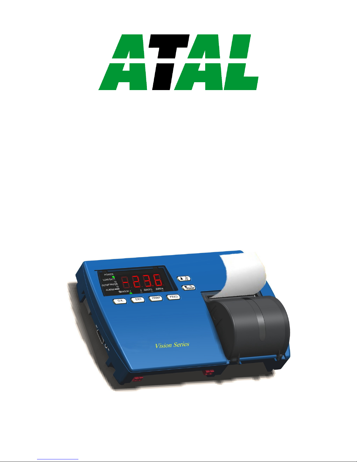
Vision Logger
Temperature Recorder
User’s Guide
AT-VLT
Page 2

Installation In s t r u c t i o n s and Pr e c a u t i o n s
1. The appliances in the p a c ka ge are d e s ig n ed for w a l l m o u n t i ng or ta ble- top installation.
2. When m o u n t i n g the pr od uct on a w a l l , be s u r e to u se the correct type of screw. Secure all s c r e w s to
pr ev e n t the pr od uct from f a l l i n g f r o m its m o u n t i n g .
3. Make all the c o n n e c ti o n s to the pr o d uc t f i r s t , and only afterwards mount the tra nsformer on the w a l l .
Safety Precautions
1. Install the p r o du ct in a dr y e n vi r o n me n t . Prevent h um id co n d it i o n s and w a t e r leakage.
2. Protect the p r o j e ct and po we r s u p p l y f r o m extreme temperatures. Do n o t install the pr o d uct near
radiators o r in di re ct s u n l i g h t .
3. Prevent any foreign objects f r o m f a l l i n g on the pr od uct . Prevent spillage of any liquids, s u c h as
s t r o n g acids.
4. Connect the power s u p p l y to the appropriate voltage, as m a rk e d on the unit.
5. In o r d er to p r e v e nt d a m ag e to c a b l e s and connectors, do not d is co nn ec t c a b l e s b y pu l l i n g on them.
6. Rou te all c a b l e s where they will not ca u s e ha za r d and ensure that the c a b l e s are not h ar m e d in any
w a y .
Warnings
1. Do n o t replace c a b l e s or connectors w i t h non-o r i g i na l p a rt s .
2. Fault c o n ne c t i o n s m a y c a u s e e l e c t r o cu t i o n .
3. The p ow er s u p p l y is designed for indoo r use only.
Page 3

Vision Recorder i
TABLE OF CONTENTS
Chapter 1 Introduction .........................................................1
Features..........................................................................................1
Description .....................................................................................2
Chapter 2 Installation.............................................................4
Package Contents............................................................................4
Installation Options.........................................................................5
Bracket Mounting ....................................................................5
Connections....................................................................................6
Mandatory Connections and Startup.........................................6
Optional Connections...............................................................7
Viewing Information on an External PC...................................7
Power .............................................................................................8
Power Source ..........................................................................8
Battery Installation and Replacement .......................................9
Chapter 3 Operation.............................................................10
Displaying Temperatures...............................................................10
Printing.........................................................................................11
Advancing and Changing Printer Paper..........................................11
Alarms..........................................................................................12
Chapter 4 Configuration ......................................................14
Online Help ..................................................................................15
Configuring Alarm Settings...........................................................15
Configuring the Alarm Range.................................................16
Configuring the Alarm Delay .................................................16
Page 4

ii Vision Recorder
Configuring the Alarm Output................................................16
Configuring the End of Paper Alarm ......................................17
Configuring Print Settings.............................................................18
Configuring Temperature and Date Formats...................................19
Changing the Time and Date .........................................................20
Changing the Password .................................................................20
Changing the Device ID................................................................21
Changing the Temperature Calibration...........................................22
Erasing the Log.............................................................................22
Changing the Sampling Rate .........................................................22
Chapter 5 Troubleshooting ..................................................23
Appendix A Factory Default Settings .....................................24
Appendix B Specifications.......................................................26
Appendix C Components.........................................................27
Appendix D Menu Structure ...................................................28
Page 5

Vision R e c o r d e r 1
CHAPTER 1 INTRODUCTION
The Vision Lo g g e r Temperature Recorder ( A T - A T - V L T ) records, saves, and p r i n t s
u p to 2 9 0 temperature r e a d i n gs a t p r e d e f i n e d intervals. T he A T - V L T produces a n
alarm w he ne ve r t h e t em p er a tu r e g o e s above o r below a defined r a n ge . T h e a l a r m
c a n be produced immediately wh en th e t em p e ra t ur e g o e s o u t o f the d e f i n e d range,
o r after the t em p er a tu r e remains o u t o f range f or a c e r t a i n period o f t im e . The A T V L T p r o v i d e s several printing o p t i o n s , including the a b i l i t y to send d a t a to an
e x t e r n a l PC. The A T - V L T c a n also send alarms to an external device v i a a relay
c o n t a c t .
The A T - V L T c a n m on i t or , log, and p r i n t t e mp e ra t ur e s o f - 4 0 °C to + 1 3 0 °C
(-40°F to + 2 6 6 °F), +\ - 1 °.
FEATURES
Table 1 d e s c r i b e s the A T - V L T f e a t ure s , w i t h references to the section a n d p a g e in this
m an u al describing how to u s e o r c o n f i g u r e the f e at u r e .
Table 1 : V ision Logger T e m p e r a t u r e R e c o r d e r F e a t u r e s
FEATURE FOR FURTHER INFORMATION S EE
Records temperatures at in ter vals of between on e and 90
m i nu t e s
Changing the Sampling Rate o n
pa g e 2 2
Produces an alarm if the temperature goes above o r
be lo w a pr ed ef i n ed range
Configuring the Alarm Range o n
pa g e 1 6
Records and d is pl ay s temperatures in e i t h e r Celsius or
Fahrenheit, and d at e in Eur opean or English ( A merican)
format
Configuring Temperature and Date
F ormats on p ag e 1 9
Records and p ri nt s 2 9 0 readings on request at any time P rinting on pa ge 1 1
Thr ee p ri nt i n g formats, inclu ding g ra ph i c o r text, and I D
nu m b er , tim e, temperatur e, and alarm s t a t u s
Configuring Print Settings on p a ge 1 8
A u d i o and vi su a l alarms, includi ng an option for sending
alarms to an external d ev i c e
Alarms on pa ge 12 and Optional
Connections on p a g e 7
Opt i o n to export d at a to ex t e r n a l PC Viewin g Information on an External
PC o n pa g e 7
Opt i o na l b ac ku p ba tt er y for up to 60 hou r s B attery Installation and Replacement
on p a g e 9
Page 6
2 Vision R e c o r d e r
D ESCRI PTI ON
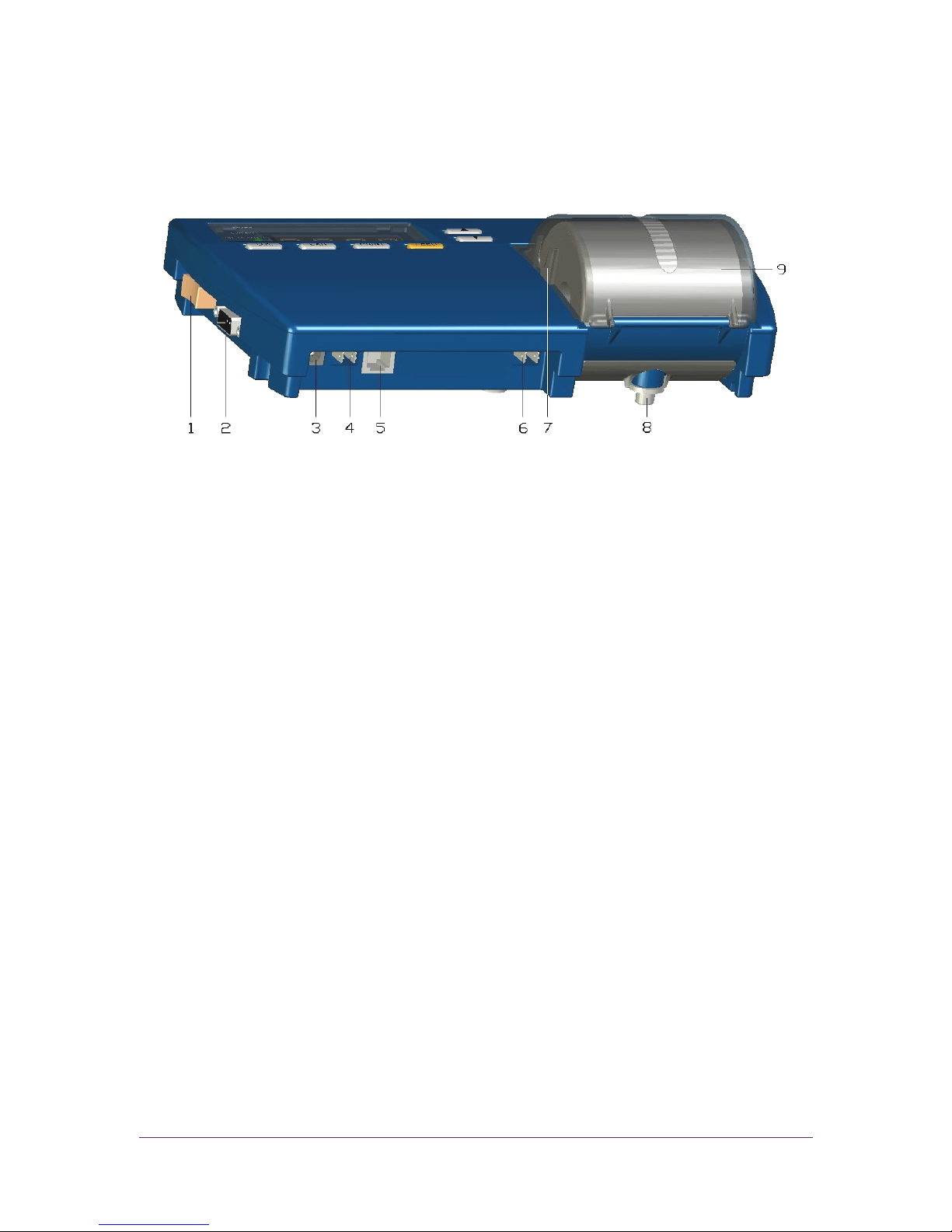
Figure 1 shows the f r o nt a n d top o f the A T - V L T .
F i g u r e 1 : V i s i o n L ogger Te m p e r a t u r e R e c o r d e r - Front/ T op V iew
1. Po w e r switch
2. RS-2 32 port
3. 12V power jack
4. Buzzer silent c o n t a c t s
5. Temperature sensor input jack
6. Remote a l a r m c o n t a c t s
7. Paper c o v e r c l i p
8. Secure to the b r a c k e t
9. Paper c o v e r
Page 7
Vision R e c o r d e r 3
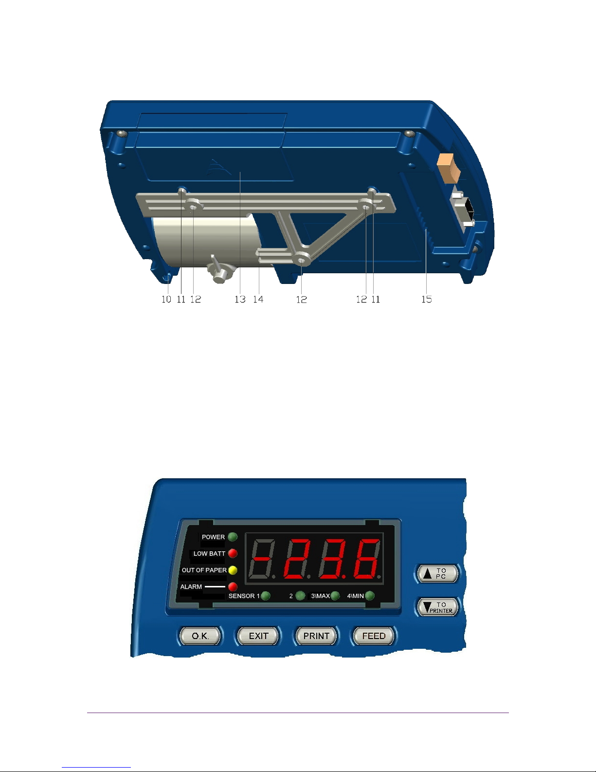
Figure 2 shows the rear and bottom o f the A T - V L T .
F i g u r e 2 : V i s i o n L ogger Te m p e r a t u r e R e c o r d e r - Re a r V i e w
10. Secure t i e hole
11. H anging hole
12. B racket h a n g i n g hole
13. B atteries c o v e r
14. B racket m ou n ti n g
15. B uzzer alarm g r i l l
Figure 3 shows the display area o f the A T - V L T .
F i g u r e 3 : V i s i o n L ogger Te m p e r a t u r e R e c o r d e r - Di s p l a y Area
Page 8

4 Vision R e c o r d e r
CHAPTER 2 INSTALLATION
This c h a p t e r explains how to install the A T - V L T , and includes t h e f ol l o w i n g topics:
▲ Pa c k a g e Co n t e n t s – L ists t he c o n t e n t s o f t he A T - V L T package.
▲ In st all at ion Op t i o n s – D escribes the poss ibl e w a y s to install the A T - V L T , and
describes how to a t t a c h th e A T - V L T to a wal l b r a c k e t .
▲ C o n n e c t i o n s – D escribes the ma n da t or y and o p t i o n a l c a b l e c o n n e c t i o n s ,
including instructions o n how to start the A T - V L T .
▲ Po w e r – Des cri bes the A T - V L T ’s p owe r r e q u i r e m e n t s and b a c k u p ba tt er y
o p e r a t i o n c a p a b i l i t y , and e x p l a i n s how to install o r replace b a t t e r i e s .
PACKAGE CONTENT S
The A T - V L T p a c k a g e s h o u l d include t h e f o l l ow i n g c o m p o n e n t s :
Table 2 : P ackage C o n t e n t s
DESCRIPTION QUA NTITY PAR T N UMBER
AT-VLT unit with on e temperature ch a n n e l 1 AT-VLT (115V),
AT-VLT220 (220V Europe)
AT-VLT12 (to vehicle)
Waterproof, remote 3 3 feet temperature sensor
c o r d (10 meters)
1 AT-VLTSENSOR
The rm al pa p e r roll, 2 inches w i d e , 131 feet long
(40 m e t er s )
2 (1 installed) V L P A P E R
12V AC/DC po we r adaptor - US (120V) OR
12V AC/DC po we r adaptor - EU (230V)
# AT-VLT12 ha s D C c o r d instead of power adaptor
1 V L 1 1 5
V L 2 2 0 ( E ur ope)
CRCPW
3.6V Lithiu m ba tt er y (CR2032) 1 (i n stalled) V L B A T
Hanging br a c k et 1 V L B R K T
User’s G uide 1 V L M A N U A L
Bracket mounting screws 3
Bracket securing screw 1
Page 9
Vision R e c o r d e r 5
INSTAL LATI ON OP TI ONS
Y o u c a n use the A T - V L T a s a standalone unit o r attach it to a wa ll. There are two wa ys
to attach the A T - V L T to a wa ll :
▲ D irect M o u n t i n g – A ttach the A T - V L T d i r e c t l y to t he wa ll.
▲ B r a c k e t M o u n t i n g – A tt a ch t h e A T - V L T b r a c k e t t o t h e w a l l , a n d h a n g t he A T - V L T o n
the b r a c k e t , a s d e s c r i b e d b e l o w .
Bracket Mounti ng
To attach the A T - V L T to the wa ll usi n g the b r a c k e t :
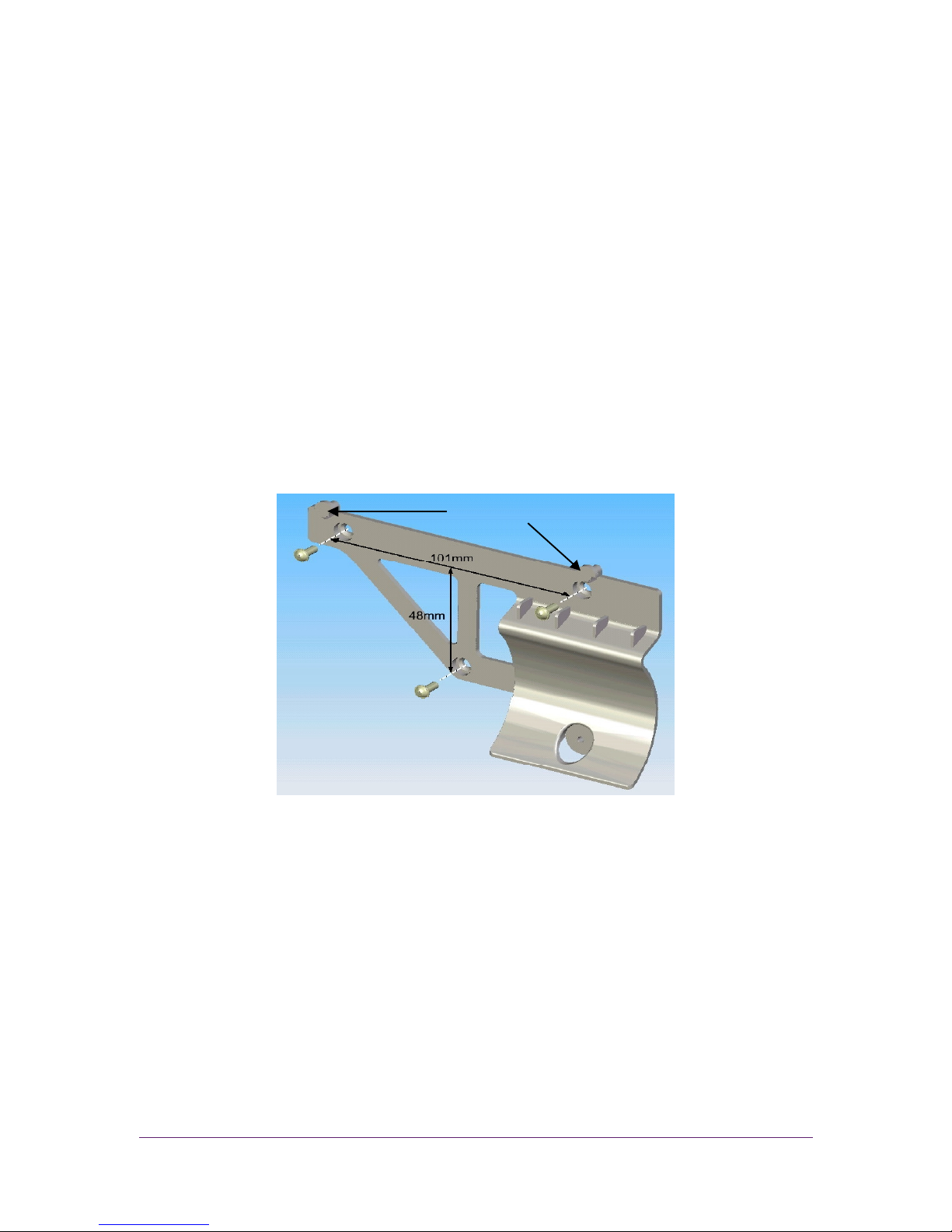
1. Mo u n t the A T - V L T b r a c k e t to the w al l wi th t h re e screws, a s shown i n Figure 4 .
Hooks
F i g u r e 4 : B r a c k e t M ounting
N o t e : Make sure to l e a ve enough space o n the left to o p e r a t e the m ai n switch
and c o n n e c t all t he o t h e r c a b l e s m e nt i on e d in C onnections o n p a g e 6.
2. H ang the A T - V L T o n the two m ou n t e d bracket hooks, as shown in Figure 4.
3. O pen the p a p e r c o v e r by pushing the two c o v e r c l i p s (it e m 7 i n Figure 1 ) to the
inside a n d pulling the c o v e r o u t .
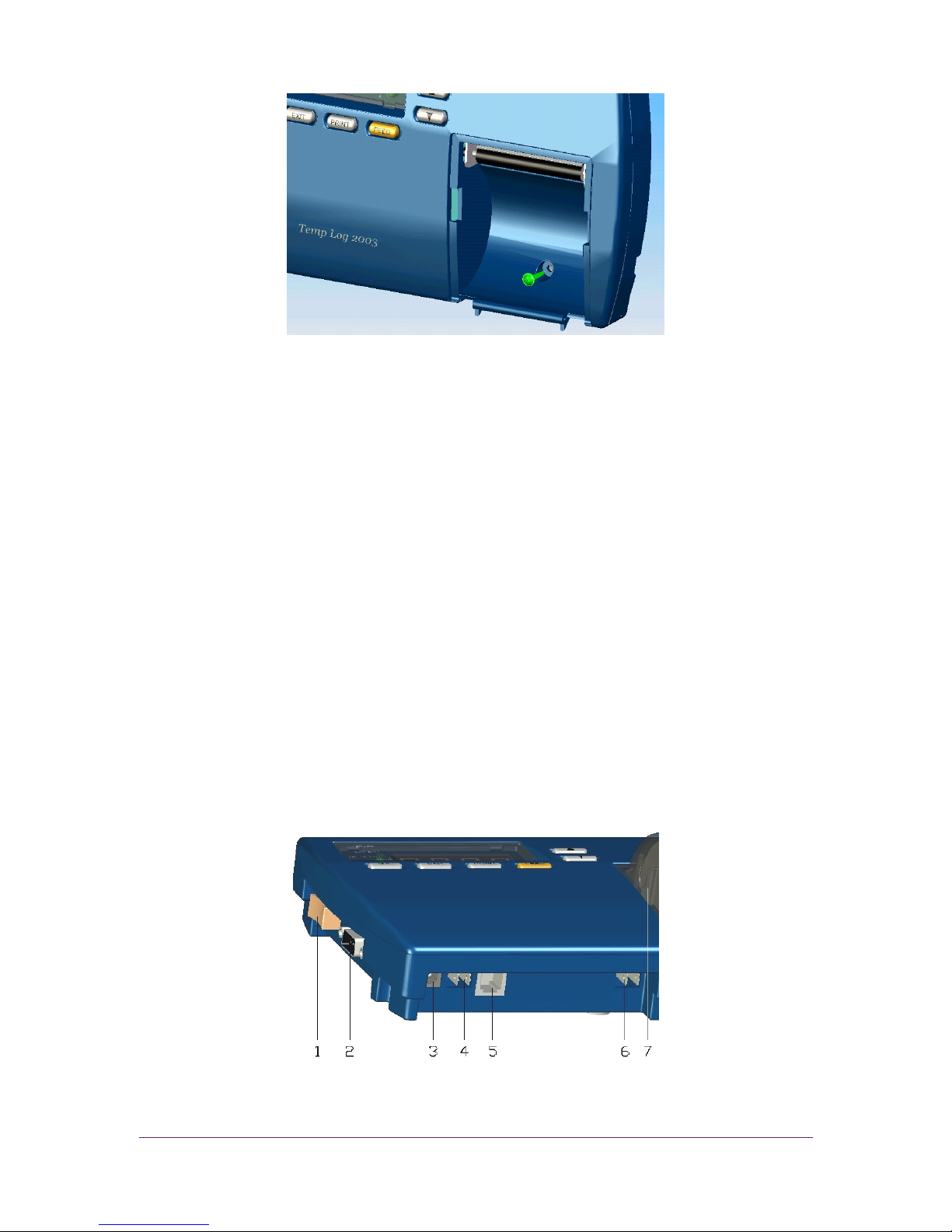
4. Fasten o n e screw through the hole under the paper roll to s e c u r e the A T - V L T to t h e
bracket, a s shown in F igure 5.
5. Return the paper c o v e r to it s p l a c e .
Page 10
6 Vision R e c o r d e r
F i g u r e 5 : S e c u r i n g the U n i t to the B racket
CONNECTIONS
This s e c t i o n describes the c a b l e s y o u m us t c o n n e c t in o r d e r to u s e th e A T - V L T , as well
as c a b l e s y o u c a n attach in o r d e r to u s e o p t i o n a l fea t u r e s .
Mandatory Connections and Startup
To c o n n e c t and s t a r t up t h e AT- VLT:
1. Plug t h e A C adaptor into th e power supply and c o n n e c t the 12V power c o r d to
the power j a ck (i te m 3 in F igure 6 ) .
2. Co n n e c t t h e temperature sensor c o r d to the temperature s e n s o r input j a ck (item 5
in Figure 6).
3. Swi tc h the power switch to the On position (it e m 1 in F igure 6). Th e Po w e r and
Sensor L E D s t ur n g r e e n . A ft e r a fe w m om ent s , the temperature s h o u l d appear in
the d i s p l a y area.
F i g u r e 6 : C onnections
Page 11

Vision R e c o r d e r 7
Optional Connections
Y o u c a n c o n n e c t t h e f ol l owi n g o p t i o n a l c a b l e s :
▲ To send a l a r m s to a remote device, a t t a c h a c a b l e to the r e m ot e alarm c o n t a c t s
(it e m 6 in F igure 6 ) . T he r e mo t e alarm c o n t a c t s are a pair o f ¼ ” terminals,
1 Amp s , 1 2 V.
▲ To export te m p er at u r e data to a P C , attach an R S - 2 3 2 c a b l e f r o m the PC to the
RS-2 32 port (it em 2 in F igure 6 ) .
▲ To silence the alarm, c o n n e c t a remote buzzer silencing device by attaching a
c a b l e w it h a mo me n t ar y switch to m o me n t ar ily short the b u z z e r s i l e n c e r
c o n t a c t s (item 4 in F igure 6). The buzzer silencer c o n t a c t s are a p a i r o f ¼ ”
terminals.
Viewing Information on an External PC
Before y o u c a n v i e w information f r om t h e A T - V L T o n an external P C , y o u m us t
establish a new H y p e r Terminal c o n n e c t i o n o n the P C .
N o t e : If y o u have a l r e a d y established a Hy p e r Terminal c o n n e c t i o n o n y o u r PC,
skip to Viewing In f o r m a t i o n on an E xternal P C o n page 8.
Establis hi ng a New Hype r Te r m i nal Co nnection
To establish a new H y p e r Terminal c o n n e c t i o n o n y o u r PC:
1. Co n n e c t an R S - 2 3 2 c a b l e f r o m the P C to the R S - 2 3 2 port (i t em 2 i n F igure 6).
2. O n t he P C , o p e n H y p e r Te r m i n a l . T o o p e n Hy p e r Terminal, s e l e c t
Start> Programs>A ccessories>C o m m u n i c a t i o n s > Hy p e r Terminal and
double- c l i c k H Y PERTRM.EXE .
N o t e : I f H y p e r Te r m i n a l is not installed o n y o u r c o m p u t e r , y o u c a n install i t
f r om the C o n t r o l P anel. Do u b l e - c l i c k A dd/Remove Programs, c l i c k th e
Windows S e t u p tab, s e l e c t C o m m u n i c a t i o n s , c l i c k D etails, select
Hy p e r T erminal, c l i c k O K , then c l i c k O K again.
3. Enter a name f o r th e A T - V L T c o n n e c t i o n .
4. Select a n icon and c l i c k O K .
5. I n the Co n n e c t to wi nd ow , g o to the lower Co n n e c t using: m en u a n d select
D irect to C o m 1 (m a k i n g sure to c h o o s e a f r e e C o m port) .
Page 12

8 Vision R e c o r d e r
6. Click O K . If the C o m port i s not fr e e , c h o o s e another port by selecting Fi le >
Properties> a n d selecting th e c o r r e s p o n d i n g C O M port, and then c l i c k OK.
N o t e : Co n f i g u r e the COM properties as f o l l ow : Bits p e r second - 9600; D ata
bits - 8; Pa r i t y - N o n e ; S top bits - 1 ; Flow control - N o n e ,
Viewi ng I nfo r matio n on a n Exte r nal PC
To v i e w in f or m at i o n f r o m the A T - V L T o n an e x t e r n a l P C :
1. Co n n e c t an R S - 2 3 2 c a b l e f r o m the P C to the R S - 2 3 2 port (i t em 2 i n F igure 6).
2. O n t he P C , o p e n t h e A T - V L T Hy p e r Terminal c o n n e c t i o n program. To o p e n it ,
select S tart> Programs> Accessories> Co m m u n i c a t i o n s > H y p e r Terminal
and double- c l i c k t h e A T - V L T Hy p e r Terminal icon that y o u previously c r e a t e d
(refer to Es t a b l i s h i n g a N e w H yper Te r m i n a l C onnection o n page 7 ) .
The A T - V L T Hy p e r Te r m i n a l w i n d o w o n the P C d i s p l a y s me s sa g e lines according to
the s a m p l i n g r a t e . T h e Hy p e r Terminal displays whate ver information the A T - V L T
prints, both m an u al l y and automatically. Fo r information o n p r i n t i n g m anu all y,
refer to P rinting o n p a g e 11. Fo r information o n p r i n t i n g a u t o m a t i c a l l y, refer to
Configuring Print S e t t i n g s o n page 1 8 .
N o t e s : To c a p t u r e lines o n e after the o t h e r , select File> Properties a n d select the
Setting tab. U nder AS CI I Se t u p , select A ppend line feed to incoming
line ends.
To c a p t u r e the d a t a to a f i le, s e l e c t T ransfer> C apture Text. E n t e r the
f i l e name a n d c l i c k S tart.
W hen the p r i n t f o r ma t is c o n f i g u r e d as g r a p h , o n l y the c u r r e n t te m pe r at u r e
and the alarm range a p p e a r in Hy p e r Terminal. O n every 1 2th row, t he d a t a
is displayed in fu l l t e xt f o r m a t.
POWER
This s e c t i o n explains the A T - V L T ’s power requirements and backup b a t t e r y o p e r a t i o n
c a p a b i l i t y , and e x p l a i n s how to install o r replace batteries.
Power Source
The A T - V L T uses a 1 2 V A C / D C power supply. When the A T - V L T is using the m a i n
power s u p p l y , the P o w e r L E D i s lit g r e e n .
Page 13

Vision R e c o r d e r 9
I n the event o f a power f a il ur e , o r if the wo rki ng e n v i r o n m e n t temperature g o e s
o v e r 150°F ( 6 5 °C), the A T - V L T a u t o m a t i c a l l y switches o v e r to a 9V b a c k u p battery ( if
installed) . W hen o p e r a t i n g i n backup m ode , the A T - V L T logs temperature
m ea s ur e m en ts to m e mo r y, but does not print. T he P o w e r L E D blinks, and the
display area shows the c u r r e n t t e mp e ra t u re every 3 0 s e c . for two seconds. Yo u c a n
also d i s p l a y the c u r r e n t t em p er a t ur e f or two seconds a t a time ma n ua l ly by pressing
. Wi th a n e w 9 V battery, the A T - V L T c a n o p e r a t e in b a c k u p m od e f o r 60 hours.
W hen the m ai n power returns, the Po w e r LED g o e s o n w i t h o u t b l i n k i n g , and the
printer prints t h e t em p er a tu r e m e a s u r e m e n t s that we re r e c or d e d b u t not printed
wh en the A T - V L T wa s o p e r a t i n g in backup m od e .
Battery I ns tallation and Repl acement
The A T - V L T uses two batteries:
▲ Lithium battery ( C R 2 0 3 2 ) – U sed f or saving logging data and c o n f i g u r a t i o n
settings, and for running the r e al - time c l o c k . Af t e r r e p la c i n g the L ithium
battery, y o u should c h e c k and r e s e t t he A T - V L T c o n f i g u r a t i o n s e t t i n g s .
▲ 9V a l k a l i n e b a c k u p b a t t e r y – U s e d f or backup o p e r a t i o n (refer to P ower
Sou rc e on pa ge 8). Thi s ba tt er y i s o ptio nal , a nd is no t inc lude d wi th th e AT -V LT
package. Wh e n the Lo w Batt LED b l i n k s , y o u should r e pla c e the 9 V backup
battery.
To c h a n g e o r i n st a ll batteries:
1. Push and slide the c o v e r o f the battery c o m p a r t m e n t o u t , a s shown in Figure 7 .
2. I nstall t h e batteries as i nd i ca t e d, according to th e polarity m a rk s i n t h e b a t t e r y
c o m p a r t m e n t .
3. Po s i t i o n t h e c o v e r o v e r th e battery c o m p a r t m e n t a n d snap it b a c k into place.
F i g u r e 7 : B a t t e r y Installation and Re p l a c e m e n t
Page 14

10 Vision R e c o r d e r
CHAPTER 3 OPERATION
This c h a p t e r explains how to o p e r a t e t he A T - V L T , a n d includes the f ol l o w i n g topics:
▲ D isplaying T emperatures
▲ Pr i n t i n g
▲ A dvancing and C h ang in g Printer Paper
▲ A larms
D I SP LAYI NG TEMPERATURE S
W hen the A T - V L T i s o n , it d i s p l a y s the c u r r e n t t emp er a t ur e . Y o u c a n a l s o display the
m ax i m um and mi n im u m m ea s ur e d t e mp e ra t u re s i n the A T - V L T ’s m e mo r y by pressing
and . The A T - V L T ’s m e m o r y c a n s t o r e up to 2 9 0 readings. T he time p e r i o d
this c o v e r s d e p e n d s o n the s a m p l i n g rate. Fo r example, if t h e sampling rate is
15 m i n u t e s , the A T - V L T ’ s internal me m or y c o n t a i n s the temperature d a t a f r o m the last
three days.
▲ Press to display the lowest temperature in m e m o r y . Press again to
display the h i g h e s t temperature in me m or y, A dJ (f o r adjusting parameters),
and to r e t u r n to the c u r r e n t te m p er at u r e. A ft e r three seconds, th e display
automatically returns to the c u r r e n t t e mp e ra t ure .
▲ Press to display A dJ (f o r adjusting parameters) . P r e ss again to
display the h i g h e s t temperature in me m or y, the lowest temperature i n m em o ry ,
and to r e t u r n to the c u r r e n t te m p er at u r e. A ft e r three seconds, th e display
automatically returns to the c u r r e n t t e mp e ra t ure .
N o t e : Y o u c a n c o n f i g u r e the A T - V L T to display temperatures in either C e l s i u s o r
Fahrenheit. R efer to Configuring T e m p e r a t u r e and Date F ormats o n
page 19.
Page 15

Vision R e c o r d e r 11
PRI NTI NG
The A T - V L T c a n be c o n f i g u r e d to print temperatures automatically at d e f i n e d intervals.
Fo r a description o f the available p r i n t m od e s and instructions o n c o n f i g u r i n g the
print s e t t i n g s , refer to C onfiguring Print S e t t i n g s o n page 1 8 .
I n addition, y o u c a n ma n ua l ly print the m e m o r y report (a l i st o f all s a v e d
m ea s ur e m en ts) o n demand, o r s e n d the report to a P C to v i e w a n d s a v e the
information. To send the m e mo r y report to the p r i n t e r o r a P C , press . SEnd
appears in the display area.
▲ To print t he me m or y report, p r e s s .
▲ To send t h e m em o ry report to a P C , press .
▲ I f y o u do not p r e s s either button wi th in three s e c o n d s , the display automatically
returns to the c u r r e n t temperature.
The A T - V L T p r i n t s o r sends the mem or y report in whi ch eve r print mo de is c u r r e n t l y
c o n f i g u r e d . I f the A T - V L T is a l s o c o n f i g u r e d to print o r s e n d m e as u re me n t s
automatically, then whe n t h e printing is f i n i s he d , the A T - V L T p r i n t s o r sends all
m ea s ur e m en ts that we re recorded during the o n demand m e m o r y report p r i n t i n g o r
sending o p e r a t i o n .
Ev e r y report that i s p r i n t e d o r s e n t o n demand begins w i t h the m es sa g e MEMORY
REP ORT and ends w i t h the m es s a ge E ND OF REP ORT . T h e p r i n t e d o r sent o n
demand r epo r t d i s p l a y s th e m e as u re m en t s i n reverse o r d e r ( i .e ., c u r r e n t
m ea s ur e m en ts are d i s p l a y e d b e f o r e the earlier m ea s ur e me n ts ).
To m an u al l y stop p r i n t i n g o r sending a report o n demand, press . Th e p r i n t o u t
o r sent report d i s p l a y s the me s sa g e MEMORY REPORT STOPPED BY USER.
N o t e : When y o u send a report to a P C , all data i s sent w i t h i n ten seconds.
AD VANCING AND CHANGI NG PRINTER PAP E R
The A T - V L T uses thermal p r i n t i n g p a p e r to p r i n t t e mp er a t ur e readings. T his type o f
paper uses heat, rather than ink, to print. T he A T - V L T ’s p r i n t e r does not p r i n t o n
o r d i n a r y paper. When o r d e r i n g replacement paper rolls, ma ke sure t o o r d e r thermal
paper.
Page 16

12 Vision R e c o r d e r
W hen a red m ar k appears o n t h e s i d e o f the p a p e r , this indicates t ha t the p a p e r roll
is a l m o s t f in i s h e d . Yo u should replace t h e paper roll before it reaches the end, so
that the p r i n t e r p a p e r w i l l not stop o r g e t s t u c k .
To replace the p a p e r roll:
1. Press two o r t h re e t i me s to advance the p a p e r .
N o t e : The button does not w ork unless t h e printer is s e t f o r automatic
printing. R efer to C onfiguring P rint Se t t i n g s o n p a g e 18.
2. Tear o u t th e latest p r i n t e d report.
3. O pen the p a p e r c o v e r a n d remove the leftover paper roll. T h e alarm buzzer wil l
sound, and the O u t o f P a p e r L E D wi ll b l i n k .
4. Straighten the edge o f the new paper roll w i t h a scissors.
5. Place the new paper roll in th e paper c o m p a r t m e n t , o r i n si d e t he o p e n paper
c o v e r , a n d push the e d g e o f the p a p e r s t r a i g h t t hr o u gh th e printer under t he
printer’s black rubber roller.
6. Press to advance the p a p e r through the printer. Af t e r installing the new
roll, the a l a r m buzzer a n d the Out o f P aper LED should g o o f f .
ALARMS
The A T - V L T h a s th e f o l l o wi n g alarm indicators:
▲ Buzzer – So m e alarms trigger an i n te r n al b u z z e r . Yo u c a n s i l e n c e th e b u z z e r
by pressing o r o n the o p t i o n a l remote b u z z e r - silencer switch. Refer to
O ptional Connections o n page 7.Yo u c a n a l s o c o n f i g u r e the A T - V L T s o that the
buzzer does not g o o n . Refer to Co n f i g u r i n g the A larm O u t p u t o n p a g e 16.
N o t e : The buzzer s i l e n c e r o n l y shuts o f f the internal buzzer sounds. The a l a r m
L E D s and the external device c o n n e c t e d to the relay contact (if enabled)
remain o p e r a t i o n a l .
▲ LE Ds – T h e fo u r LEDs to the l e ft o f t h e display area indicate v a r i o u s alarms,
as described below. Th e top LED i nd i ca t es that the A T - V L T ’s power is o n .
▲ R elay C o n t a c t to E x t e r n a l D evice – Yo u c a n c o n n e c t the e x t e r n a l device to
the A T - V L T remote a l a r m c o n t a c t s (it e m 6 in F igure 6 o n page 6 ) a n d c o n f i g u r e
the A T - V L T to s e n d a l a r m s to the e x t e r n a l device v i a a normally o p e n r e l a y
c o n t a c t . Refer to C onfiguring the A larm O u t p u t o n page 16.
Page 17
Vision R e c o r d e r 13
The f o l l o wi n g events trigger an a l a r m :
▲ D isconnected Temperature Sensor – I f the temperature sensor is
disconnected f r om the A T - V L T , th e display area shows the m es s a ge n OS, the
A larm L E D l i gh t s, and the i nt e rn a l buzzer sounds ( if enabled) .
▲ A larm R ange – I f the m e a s u r e d temperature g o e s o u t s i d e the m ax i mu m o r
m in i m um defined temperature range fo r a c o n s e c u t i v e period o f t i me e q u a l to
the defined a l a r m delay period ( if any), an a l a r m is sent. The i nt e r na l b u z z e r
sounds (if enabled), and an a l a r m i s sent to an external device v i a the r e l a y
c o n t a c t (if enabled). In addition, the Alarm L E D lights. F o r instructions o n
c o n f i g u r i n g the buzzer and r e l a y contact to respond to A larm R ange a l a r m s ,
refer to C onfiguring the A larm Output o n p a g e 16.
▲ End o f Paper – I f the printer p a p e r runs o u t , the i nte r na l buzzer sounds ( if
enabled) , and an a l a r m is s e n t to an external device v i a the relay contact ( if
enabled) . I n addition, the O ut o f P aper L E D l ig h t s. Fo r instructions o n
c o n f i g u r i n g the buzzer and r e l a y contact to respond to O ut o f P aper alarms,
refer to C onfiguring the E nd o f Paper Alarm o n p a g e 17.
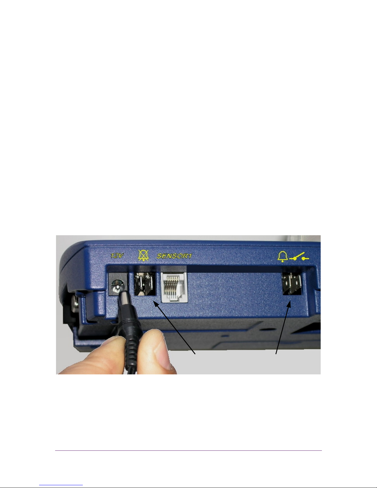
Figure 8 provides a c l o s e - up o f the r e a r panel, including the remote alarm c o n t a c t s
o n the r i g ht s i d e a n d the remote buzzer s i l e n c i n g device c o n t a c t s o n the left side.
F i g u r e 8 : R e a r P anel Cl o s e-Up
Remote a l a r m
c o n t a c t s
Buzzer silencing
c o n t a c t s
Page 18

14 Vision R e c o r d e r
CHAPTER 4 CONFIG URATION
This c h a p t e r explains how to c o n f i g u r e the A T - V L T . T o c o n f i g u r e A T - V L T parameters,
y o u m us t e n t e r a password. The default password is . Fo r
instructions o n c h a n g i n g y o u r password, refer to Changing the P assword o n
page 20.
To c h a n g e the A T - V L T c o n f i g u r a t i o n :
1. Press o r until A dJ a p p e a r s in the display area.
2. Press . PASS appears in the d i s p l a y area.
3. Enter y o u r password. AL r appears in the display area. AL r allows y o u to
c h a n g e the alarm settings.
4. The A T - V L T h a s n i n e root m e nu it e m s. To scroll t hr o ug h th e root m en u it e ms , p r e s s
. To scroll through the root me n u items in re v e r s e o r d e r , press . Th e
f ol l owi n g are t h e root me n u items:
Ñ A Lr – A larm c o n f i g u r a t i o n
Ñ Pr n – P rinting c o n f i g u r a t i o n
Ñ SCAL –Temperature units and d a t e f or m a t c o n f i g u r a t i o n
Ñ C Lo C – Date and time c o n f i g u r a t i o n
Ñ C hPA – C hange password
Ñ SIdn – ID number c o n f i g u r a t i o n
Ñ C AL b – Temperature c a l i b r a t i o n
Ñ Lo 9r – Erasing the logging m e a su r e me n ts f r o m the m e mo r y
Ñ SAPr – S ampling r a t e c o n f i g u r a t i o n
N o t e : Fo r a f u l l d i a g r a m o f the A T - V L T m e nu tree, refer to A ppendix D, Me n u
Structure o n p a g e 28. Fo r a li s t o f the default f a c t or y settings, refer to
A ppendix A , F actory D e f a u l t S e t t i n g s o n p a g e 24.
5. W hen y o u reach the root m e nu item that y o u wa nt , press . The f i rs t
sub- m e n u i t em appears.
6. W hen y o u have fi n is he d c o n f i g u r i n g an item, y o u mus t p r e s s to save the
c o n f i g u r a t i o n c h a n g e s .
Page 19

Vision R e c o r d e r 15
ONLINE HELP
The A T - V L T o f f e r s o n l i n e h e l p that explains the short f o r ma t display m as s a ge s and
g u i d e s y o u through the men u c o n f i g u r a t i o n s .
1. O pen the p a p e r c o v e r to best v i e w the p r i n t e d o n l i n e help m es s a ge s.
2. I f y o u wa n t help o n a n y m e n u i t e m , press . The A T - V L T wi l l print and/ o r
send t h e o n l i n e help me s s ag e in wh iche ve r fo r m a t is c u r r e n t l y configured
(as d e s c r i b e d i n C onfiguring P rint Se t t i n g s o n p a g e 18).
N o t e : The k e y c a n be used to access the o n l i n e help in a l l s i t u a t i o n s , except
wh il e the c u r r e n t te m p er a tu r e is being d i s p l a y e d .
3. The A T - V L T p r i n t s and/o r sends a blank li n e after every o n l i n e help m e s s a g e .
N o t e s : Y o u c a n n o t p r i n t o n l i n e help unless the printer is set f o r automatic
printing. R efer to C onfiguring P rint Se t t i n g s o n p a g e 18.
I f the A T - V L T is c o n f i g u r e d to send o u t p u t to an e x t e r n a l P C , h e l p m e s s a g e s
wi ll also be s e n t to the external PC.
CONFIG URING ALARM SETTINGS
To c o n f i g u r e a l a r m settings, d i s p l a y the A Lr root me nu . F rom the AL r root m en u ,
y o u c a n c o n f i g u r e the f o l l o w i n g a l a r m s e t t i n g s :
▲ A larm R ange S et ( A L S ) – Allows y o u to define a temperature range. When
the c u r r e n t temperature i s o u t s i d e o f this r a n ge , the A T - V L T sends an a l a r m .
▲ A larm D elay ( A L d l ) – A llows y o u to define an a l a r m delay. If the c u r r e n t
temperature g o e s o u t o f the defined tem p er a tu r e range, the A T - V L T does not s e n d
an alarm until the temperature r e m a i n s o u t s i d e o f the range f o r the l e n gt h o f
time d e f i n e d by the Alarm D e l a y parameter.
▲ A larm O u t p u t (ALO) – A llows y o u to define w het he r o r not t h e A T - V L T ’s
internal a l a r m sounds wh en an alarm i s sent, and wh et her o r not a l a r m s a r e sent
to an external device.
▲ End o f Paper Alarm ( E O F P ) – Allows y o u to define wh eth er o r n o t the
A T - V L T ’s in t e rn a l a l a r m sounds, a n d wh et her o r not a l a r m s are sent to an external
device, w h e n t h e paper runs o u t .
Page 20

16 Vision Recorder
Configuring the Alarm Range
To configure the high and low temperatures that will trigger an alarm:
1. From the ALr menu, press . ALS appears.
2. Press . LoA1 appears. Press or to set the minimum temperature.
Temperatures below this temperature will trigger an alarm.
3. Press . HIA1 appears. Press or to set the maximum temperature.
Temperatures above this temperature will trigger an alarm.
4. Press . The changes are saved and ALS appears.
Ñ To change other alarm settings, press or to display the other
alarm menu items.
Ñ To go to another root menu item, press again, then press or
to display the other root menu items.
Ñ To exit configuration and display the current temperature, press
twice.
Configuring the Alarm Delay
To configure the alarm delay:
1. From the ALr menu, press . ALS appears.
2. Press . ALdl appears.
3. Press . The current alarm delay setting appears.
4. Press or to scroll among the possible alarm delay values: n0 (no
delay), 10 (minutes), 30 (minutes), 1 h (1 hour), and 2 h (2 hours). When the
value you want to select appears, press . ALdl appears.
5. Press . The changes are saved and ALr appears.
6. Press again to exit configuration and display the current temperature.
Configuring the Alarm Output
To configure the alarm output:
1. From the ALr menu, press . ALS appears.
2. Press or twice. ALO appears.
Page 21

Vision Recorder 17
3. Press . The current alarm buzzer setting appears:
Ñ buOn – The internal buzzer will sound when there is an alarm.
Ñ buOF – The internal buzzer will not sound when there is an alarm.
4. To keep the current setting, press . To change the setting, press or
to toggle the setting, then press . The current external Normally Open
contact device setting appears:
Ñ CoOn – The external Normally Open contact is closed and a signal is
sent to the external device when there is an alarm.
Ñ CoOF – A signal is not sent to the external device when there is an
alarm.
5. To keep the current setting, press . To change the setting, press or
to toggle the setting, then press . ALO appears.
6. Press . The changes are saved and ALr appears.
7. Press again to exit configuration and display the current temperature.
Configuring the End of Paper Alarm
To configure the End of Paper alarm output:
1. From the ALr menu, press . ALS appears.
2. Press . EOFP appears.
3. Press . The current End of Paper alarm buzzer setting appears:
Ñ buOn – The internal alarm sounds when the printer is out of paper.
Ñ buOF – The internal alarm does not sound when the printer is out of
paper.
4. To keep the current setting, press . To change the setting, press the or
button to toggle the setting, then press . The current End of Paper
external device setting appears:
Ñ CoOn – An alarm is sent to the external device when the printer is out of
paper.
Ñ CoOF – An alarm is not sent to the external device when the printer is
out of paper.
5. To keep the current setting, press . To change the setting, press or
to toggle the setting, then press . EOFP appears.
6. Press . The changes are saved and ALr appears.
7. Press again to exit configuration and display the current temperature.
Page 22

18 Vision R e c o r d e r
CONFIG URING PRI NT S ETTI NGS
To c o n f i g u r e p r i n t s e t t i n g s , display the Prn root me nu . F rom the Pr n root me nu ,
y o u c a n c o n f i g u r e the f o l l o w i n g print settings:
▲ Pr i n t Fo r m a t – A llows y o u to c h o o s e f r o m among three p r i n t f o r ma t s . B o t h
the A T - V L T printer o u t p u t a n d the external PC o u t p u t w il l u s e t he selected f o r m a t.
▲ P ri nte r – All ow s you to def in e whe the r or not th e AT- VLT au tomat ic al ly pri nt s
t em pe ra tu re re ad in gs . W h en t he p r in te r is s e t to p ri nt au to ma ti c al ly , t he A T - V L T
prints each temperature r e a d i n g that i t m e as u res , a t the defined me a s ur e me nt
intervals. Refer to Changing t h e S ampling Rate o n page 22.
▲ PC Output – Al lo ws y o u to define w het he r o r not the A T - V L T sends te m p er a tu r e
readings to a n external PC.
To c o n f i g u r e p r i n t s e t t i n g s :
1. From the Prn m e n u , press . The c u r r e n t p r i n t f or m a t appears:
Ñ LCh r – T h e A T - V L T p r i n t s and sends o u t p u t to an external PC us in g a large
c h a r a c t e r f or m a t . E ach temperature r e c or d i nc l ud e s the fo l l o w i n g
information: D ate, t im e, and te m p er at u r e. T h e f o l l ow i n g is an e x a m p l e o f
a temperature record in large c h a r a c t e r f or m a t :
29 15:32 78.0F AL
I n this example, the d a t e is t h e 2 9
t h
o f the c u r r e n t m on t h, the time is
15:32 (3:32 p .m .) , th e t e mp e ra t u re is 7 8 . 0 °F , and the a l a r m is activated.
Ñ SCh r – T h e A T - V L T p r i n t s and s e n d s o u t p u t to an external P C using a small
c h a r a c t e r f or m a t . E ach temperature r e c or d i nc l ud e s the fo l l o w i n g
information: I D of the unit r e c or d i n g t he m e as u re m e nt , time, date, a n d
temperature. The f o l l ow i n g is a n example o f a temperature r e c or d in
small c h a r a c t e r f o r m a t :
SUPCO 12345 04/29/04 15:32 78.0F A
I n this example, the I D o f the A T - V L T unit is S U P C O 1 2 3 4 5 ( refer to
Changing t h e D e v i c e I D o n page 21), the d a t e is A pril 2 9 , 2 0 0 4 ( refer to
Changing t h e T ime a n d D ate o n page 20), the ti m e is 1 5 : 3 2 ( 3 : 3 2 p .m .),
and the temperature is 7 8 . 0 °F , and t he a l a r m i s activated.
Ñ 9rA P – Th e A T - V L T p r i n t s in a g r a p h f o r ma t . The g r a p h f o r mat prints
temperature m e as u re m en t s i n the f o r m o f a c u r v e d g r a p h . E v e r y
temperature v a l u e is printed n e x t to the relevant g r a p h point. T he
m in i m um and ma x im u m t em p er a tu r e thresholds a r e shown as s e p a r a t e
striped l i n es , a n d the temperature r a ng e v a l u e s a r e p r i n t e d in t e xt every
12
th
row. If temperature range alarms a r e e n a b l e d , the letter A appears
Page 23

Vision R e c o r d e r 19
next to any line in whi ch t he t e mp e r at u re is o u t s i d e o f the defined
temperature range a n d the delay time has elapsed. In every 1 2th row, fu l l
information is p r i n t e d in small c h a r a c t e r f o r m a t .
N o t e : W hen information i s printed to an external PC in g r a p h f o r m a t , the c u r r e n t
temperature and the a l a r m range are printed, but the g r a p h itself is n o t
printed.
2. To keep t h e c u r r e n t setting, press . To c h a n g e the setting, p r e s s o r
to toggle the s e t t i n g , then p r e s s . Th e c u r r e n t p r i n t e r setting a p p e a r s :
Ñ Pr On – T h e A T - V L T p r i n t e r prints temperature records automatically at the
defined me a s ur e me n t intervals.
Ñ Pr O F – T h e A T - V L T p r i n t e r does not print temperature r e c or d s unless y o u
request a printout ma n ua l l y. Refer to P rinting o n page 11.
3. To keep t h e c u r r e n t setting, press . To c h a n g e the setting, p r e s s o r
to toggle the s e t t i n g , then p r e s s . Th e c u r r e n t P C o u t p u t setting
appears:
Ñ PCOn – T he A T - V L T sends t em p er a t ur e records to an external PC
automatically at the d e f i n e d m eas u re m en t i nt e rv a ls .
Ñ PCOF – The A T - V L T printer does not s e n d t e mp era t ur e records unless y o u
request i t to send o u t p u t m a n u a l l y . Refer to P rinting o n page 11.
4. To keep t h e c u r r e n t setting, press . To c h a n g e the setting, p r e s s o r
to toggle the s e t t i n g , then p r e s s . Pr n appears.
5. Press to save y o u r c h a n g e s , e x i t c o n f i g u r a t i o n , and d i s p l a y the c u r r e n t
temperature.
CONFIG URING TEMP ERATURE AND D ATE F O RMATS
To c o n f i g u r e the f o r m a t in wh ich t he A T - V L T displays temperatures (Celsius o r
Fahrenheit) and dates ( E uropean o r A me r i ca n ):
1. Display the SCAL root me n u.
2. From the SCAL m enu , p r e s s . The c u r r e n t temperature f o r mat appears:
Ñ F d9 – F ahrenheit
Ñ C d9 – Celsius
3. To keep t he c u r r e n t setting, press . To c h a n g e the setting, p r e s s o r
to toggle the s e t t i n g , then p r e s s . Th e c u r r e n t date f or m a t appears:
Ñ EndA – E nglish ( A m e ri c an ) date f o r m a t (mm/d d /y y )
Ñ EudA – E uropean date f o r m a t ( d d /m m/y y )
Page 24

20 Vision R e c o r d e r
4. To keep t h e c u r r e n t setting, press . To c h a n g e the setting, p r e s s o r
to toggle the s e t t i n g , then p r e s s . SCAL appears.
5. Press to save y o u r c h a n g e s , e x i t c o n f i g u r a t i o n , and d i s p l a y the c u r r e n t
temperature.
CHANGI NG THE TIM E AND D ATE
To c h a n g e the time and date:
1. Display the CL o C root m enu .
2. From the C Lo C me n u, p r e s s . SdA Y appears.
N o t e : To keep th e c u r r e n t d a t e and c h a n g e the time, press o r to toggle
the s e t t i n g to Shr, th en f o l l ow the instructions starting at number 4 .
3. To c h a n g e the date, p r e s s . Th e c u r r e n t mo n th appears in n u m e r i c a l f o r m a t
(01 = January, 02 = February, etc. ) . P ress o r to c h a n g e the s e t t i n g ,
then p r e s s . Th e c u r r e n t day o f the mo n th appears. P ress o r to
c h a n g e the setting, then press . The l a st two numbers o f the y e a r appears.
Press o r to c h a n g e the s e t t i n g , then p r e s s . Shr appears.
4. To c h a n g e the time, p r e s s w he n Shr i s displayed. Th e c u r r e n t hour
appears. Pr e s s o r to c h a n g e t he setting, th en p r e s s . The c u r r e n t
time in m i n u t e s appears. P ress o r to c h a n g e the s e t t i n g , then press
. CL o C a p p e a r s .
5. Press to save y o u r c h a n g e s , e x i t c o n f i g u r a t i o n , and d i s p l a y the c u r r e n t
temperature.
CHANGI NG THE PAS SWORD
To c h a n g e the A T - V L T p a s s w o r d :
1. D isplay the C hPA root me n u.
2. From the C hPA m e nu , p r e s s . PASS appears.
3. Enter a sequence o f f o u r keys. PASS appears again.
4. Enter the same s e q u e n c e o f f o u r keys to c o n f i r m the password. If the s e c o n d
sequence is t he same as the f i r s t sequence, ChPA appears. If it is not, PASS
appears again, and y o u mu s t r e p ea t s t e p s three and f o u r .
5. Press to save the new password, exit c o n f i g u r a t i o n , and display the c u r r e n t
temperature.
Page 25
Vision R e c o r d e r 21
CHANGI NG THE D EVICE ID
The AT-VLT has a device ID that appears in temperature reports. The purpose of the
device ID is to identify the device producing p r i n t o u t s and r e p or t s whe n printouts
and reports a r e being c o l l e c t e d f r o m m or e th a n o n e device.
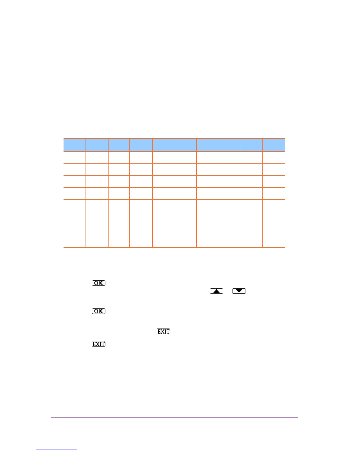
The device ID c o n s i s t s o f 1 1 a l p h a n u m e r i c c h a r a c t e r s . Y o u c a n c h a n g e each
c h a r a c t e r individually by entering a numerical c o d e o f o n e o r two n u m b e r s . T a b l e 3
shows t he c o d e fo r setting the d e v i c e ID.
Table 3 : N umerical C ode for Se t t i n g D e v i c e I D
CHR. CODE CHR. CODE CHR. CODE CHR. CODE CHR. CODE
0
0
8
8
F
16
N
24
V
32
1
1
9
9
G
17
O
25
W
33
2
2
10
H
18
P
26
X
34
3
3
A
11
I
19
Q
27
Y
35
4
4
B
12
J
20
R
28
Z
36
5
5
C
13
K
21
S
29
-
37
6
6
D
14
L
22
T
30
7
7
E
15
M
23
U
31
To c h a n g e the device ID:
1. D isplay the SIdn root me n u.
2. Press . The n u m b e r 1 a p p e a r s , f ol l o w e d by a space and a c o d e f or th e fi r s t
I D c h a r a c t e r that wi ll a p p e a r i n the d e v i c e . Press o r to c h a n g e the
c h a r a c t e r , according to the c o d e i n Table 3 .
3. Press to m ov e o n to the next c h a r a c t e r . Repeat t hi s procedure f o r e a c h
c h a r a c t e r .
4. W hen y o u are fi n i s h e d , p r e s s to save y o u r c h a n g e s . SIdn appears.
5. Press again to e x i t c o n f i g u r a t i o n a n d display the c u r r e n t temperature.
Page 26

22 Vision R e c o r d e r
CHANGI NG THE TE MP ERATURE CALIB RATION
To c h a n g e the temperature c a l i b r a t i o n :
1. D isplay the C AL b root m e nu.
2. Press . The n u m b e r 0.0 a p p e a r s .
3. Press o r to raise o r lower the t em p er a tu r e m e a s u r e m e n t , i n steps o f
0.1° . Yo u c a n raise o r lower the m e a s u r e m e n t by - 2 ° to 2 ° in o n e action.
4. W hen y o u are fi n i s h e d , p r e s s . C A L b appears.
5. Press to save y o u r c h a n g e s , e x i t c o n f i g u r a t i o n , and d i s p l a y the c u r r e n t
temperature.
E RASING THE LOG
The A T - V L T s a v e s the last t emp er a t ur e m e a s u r e m e n t s ( up to 2 9 0 logs). To erase the
log:
1. D isplay the Lo 9r root m e nu .
2. Press . The log is erased, a n d ALr appears.
3. T h e A T - V L T w i l l pri nt and o r s e n d the m e s s a g e MEMORY RESET BY USER,
< date> , < t i m e > i n the c u r r e n t l y c o n f i g u r e d print fo r m a t .
4. Press to exit c o n f i g u r a t i o n and d i s p l a y the c u r r e n t t e mp e ra t u re .
CHANGI NG THE SAMP LI NG RATE
The A T - V L T m e as u r es temperatures at defined intervals. T o c h a n g e the intervals at
wh ic h temperatures a r e m e as u re d :
1. Display the SAPr root m en u .
2. Press . The c u r r e n t sampling r a t e a p p e a r s . T h e sampling rate c a n be any
v a l u e between 1 a n d 9 0 m i nu t es .
3. Press o r to c h a n g e the s a m p l i n g rate. W hen y o u are f i n i s h e d , p r e s s
. SAPr appears.
4. Press to save y o u r c h a n g e s , e x i t c o n f i g u r a t i o n , and d i s p l a y the c u r r e n t
temperature.
Page 27

Vision R e c o r d e r 23
CHAPTER 5 TROUBLESHOOTING
Table 4 lists c o m m o n problems and suggested solutions.
Table 4 : T roubleshooting
PROBLEM SUGGEST ED SOLUTIONS
No p o w er Wait f i v e seconds after switching on the po w e r switch.
Poor or no pr in ti n g
· Make s u r e y ou are u si n g thermal p r i nt i ng p ap er . The AT-VLT
w i l l not p ri nt on no n - thermal p ap er .
· Replace the pr in ti ng s i d e of the thermal p ap er , o r replace the
ther mal p ap er it sel f.
· M ove the AT-VLT t o a location with a temperature between 0 to
149°F (-1 8 to 6 5 °C).
Wrong ti me or d at e
· Cha ng e the time or d a t e . Refer to Changing the Tim e and
Date on p a g e 2 3 .
· Make s u r e yo u are u s i n g the c o r re c t d a t e f o r m a t (d d/mm/yy o r
mm/dd /yy). Refer to C onfiguring Temperature and Date
F ormats on p ag e 1 9 .
· Replace the Lithium b at te ry ( C R 2 0 3 2 ) . R efer to B attery
Installation and Replacement o n pa g e 9.
Cannot p ri nt o nl i ne help
Cha n g e the p ri nt mode to P rOn. R efer to P rinting o n pa g e 1 1 .
Page 28
24 Vision Recorder
APPENDIX A FACTORY DEFAULT SETTINGS
To restore the Vision Recorder to its factory default settings:
1. Switch the power switch off.
2. Switch the power switch back on while pressing .
3. When FAdF appears in the display area, press .
Note: Restoring factory settings does not delete the temperature logs.
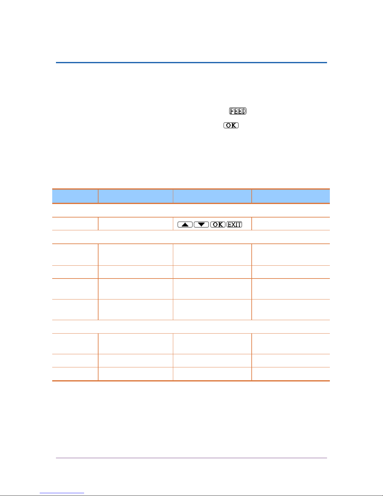
Table 5 lists the factory default settings.
Table 5: Factory Default Settings
MENU ITEM PARAMETER DEFAULTS LEGAL VALUES
PASSWORD SETTINGS
PASS Password
ALARM SETTINGS (AL.)
ALS Alarm Range Settings
Min: -4° F (-20°C)
Max: 86°F (30°C)
-67°F to 302°F
(-55°C to 150°C)
ALdl Alarm Delay No No, 15, 30 min, 1, 2 hr
ALO Alarm Output BuOn (buzzer On)
CoOn (contact On)
buOn/buOF
CoOn/CoOF
EOP End of Paper BuOn (buzzer On)
CoOn (contact On)
buOn/buOF
CoOn/CoOF
PRINT SETTINGS (PRN)
Print Format SChr (small character) LChr (large), SChr
(small), 9rAP (graph)
Printer On/Off PrOn (Printer On) PrOn, PrOF
PC Output On/Off PCOn (PC Output On) PCOn, PCOF
Page 29

Vision R e c o r d e r 25
MENU ITEM PA RA M ETER DEFAULTS LEGAL V A LUES
TEMPERATURE AND DA TE FORMATS (SCAL)
# AT-VLT # AT-VLT220
Te m p e r a t u r e
For ma t
F d9
(Fahrenheit)
C d9 (Celsius) C d9 (Celsius),
F d9 (Fahrenheit)
Date F ormat EndA , E nglish,
(mm/dd/yy)
EudA , E urope,
(dd /mm/yy)
EudA ( dd/mm/y y),
EndA ( mm/dd/y y)
CURRENT DA TE AND T IME (CLOC)
# AT-VLT # AT-VLT220
SdA Y Date 12/31/04 31/12/04
Shr Time 12:00 12:00
DEVICE ID NU MBER (SIDN )
SIdn Device ID Number SUPCO 12345
TEMPERATURE CAL I BR ATION (CALB)
CALb Te m p e r a t u r e
Calibration
0° –2° to 2 °
SAM P LI N G RA TE (SAPR)
SAPr Sampling R ate 10 m i n 1 to 9 0 m i nu t e s
Page 30

26 Vision R e c o r d e r
APPENDI X B SP ECIFICATIONS
Table 6 lists the A T - V L T ’s specifications.
Table 6 : S pecifications
DESCRIPTION SPECIFICATION
Te m p e r a t u r e Mea s u r e m e n t Range
- 4 0 ° F to + 2 6 6 °F ( -4 0°C to +130°C)
Te m p e r a t u r e Mea s u r e m e n t Accuracy
+/- 1.8°F (+ /- 1 °C)
Ambient Op er at in g Temperature R ange
0°F to + 1 5 0 °F (- 18 °C to +65°C) n o n -co n d e n s i n g
Ambient Op er at in g Rel a t i v e H umidity 0 to 9 5 % non-co n d e n s i n g
Te m p e r a t u r e Writing and S torage R esolution
0.2°F ( 0. 1° C)
Storage T emperature Range
- 4 0 ° F to + 1 5 0 °F ( -4 0°C to +65°C)
Te m p e r a t u r e Sensor Co rd Le n g t h ( extensible) 33 feet (10 m )
Te m p e r a t u r e Sensor Dia met er 0.25 inche s ( 6 . 3 5 mm)
A larm C ontact Rating 1 Amps, 12 V AC/DC
The rm al Ch ar t Paper Width 2 inches ( 5 0 . 8 cm)
The rm al Ch ar t Paper Length 131 f e e t (40 m )
Displa y Numeric L E D D isplay, 4 characters
Primary Power Su pp l y V L 1 1 5 : 1 1 5 V A C , 5 0 / 6 0 H z
V L 2 2 0 : 2 2 0 ~240V AC, 50/60 Hz
A lternative P ower Su p p ly 12V AC/DC, 1.5 Amps ( for vehicle op er a t i on
w i t h adapter, not s u p p l i e d )
Battery B ackup 9V ba t t er y , lo g s u p to 5 0 hours ( not s u p p l i e d )
Clock Battery 3.6V Lithiu m ba tt er y, two years in average u s e
(s u p p l i e d )
Size 8.2 x 5 . 3 x 2 .7 inches ( 2 0 8 . 6 x 1 3 5 x 6 9 mm)
Page 31

Vision R e c o r d e r 27
APPENDI X C COMPON ENTS
Table 7 lists the A T - V L T ’s c o m p o n e n t s , i nc lu di n g o p t i o n a l c o m p o n e n t s .
Table 7 : C omponents
DESCRIPTION SUPPLIED PAR T N UMBER
AT-VLT w i t h temperature channel 1
Te m p e r a t u r e Sensor, 33 feet (10 m ) 1 AT-VLTSENSOR
2” thermal p a p er roll, 131 f e e t length ( 4 0 m ) 2 V L P A P E R
12V AC/DC, power adaptor: USA: 130V AC o per at i o n
Europe: 230V AC o pe ra ti on
1 V L 1 1 5
V L 2 3 0
3.6V Lithiu m ba tt er y 1 V L B A T
User’s M anual 1 V L M A N U A L
Wall mounting br a c ke t 1 V L B R K T
Paper compartment cover Opt i o na l VLPACO
Battery compartment cover Opt i o na l VLBACO
IP65 c l ea r c a s e and h i n g e, 9.8 x9.8x 4” (25x25x 10cm) Opt i o na l VLWPCASE
Silencer remote kit, 16.4 feet (5 m ) Opt i o na l VLSK
Ex te ns io n ca b l e for temperature sensor, 10 f e e t (3m ) Opt io na l CABLE10H
Ex te ns io n ca b l e for temperature sensor, 33 f e e t (10m ) Opt io na l CABLE33H
RS-232 serial da ta c a b l e, 6 feet (1.8m) Opt i o na l RSCABLE
Vehicle p ow er reducer f r o m 2 4 V D C to 12V DC Opt i o na l VPR
A u t o m a t i c telephone di al er Opt i o na l
115V
Opt i o na l
230V
A D T A
A D T A 2 2 0
Remote A larm Opt i o na l RA25
DC power Cor d ( for vehicle O peration) Opt i o na l CRCPW
Page 32
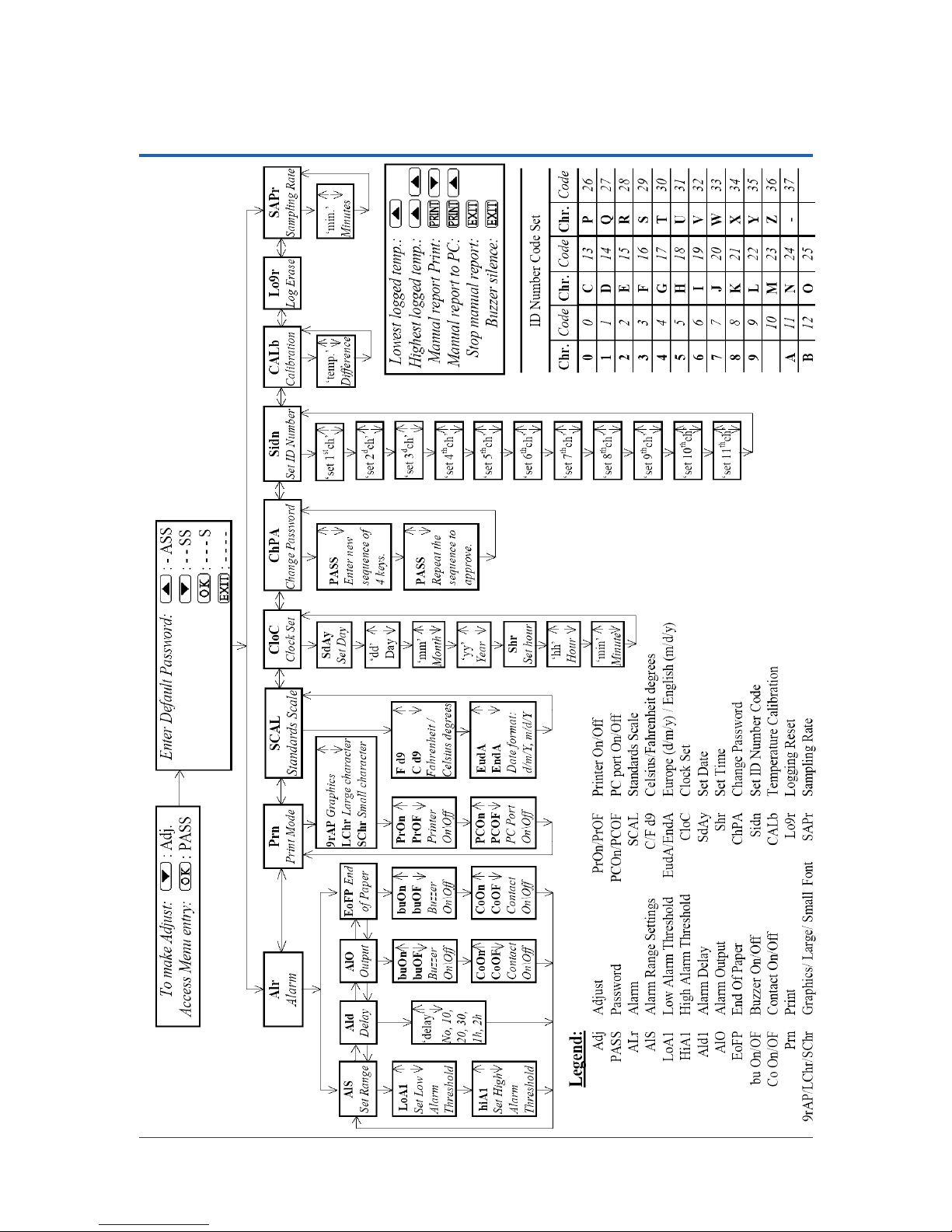
28 Vision Recorder
APPENDIX D MENU STRUCTURE
 Loading...