

Page 1

TEA-101D TRANSMITTER
Programmable temperature transmitter with 4-20 mA output
Instruction Manual
Page 2

2
Instruction manual for use of TEA-101D transmitter
Transmitter is designed for measurement of ambient air temperature at °C or °F. Measuring
temperature sensor is non-removable instrument part. Measured temperature is displayed on LCD
display. It is possible to switch OFF the LCD display. Transmitter is connected to circuitry by
current loop. Please read instruction manual before the first device connection.
All transmitter setting is performed by means of the PC connected via the optional
communication cable (not included in delivery). Program Tsensor for transmitter setting is
available at ATAL B.V.. Program enables to set measured range and on/off the LCD display. It
supports make the adjustment of the device too. This procedure is described at file „Calibration
manual.pdf“ which is installed commonly with the software.
Device setting from the manufacturer
Transmitter is set from the manufacturer to the following parameters:
value at output I1: temperature, range 4 – 20 mA corresponds to -30 to +80 °C
display: switched ON
Modification of the setting is possible to do by means of the PC using procedure described
at the end of this document.
Installation of the transmitter
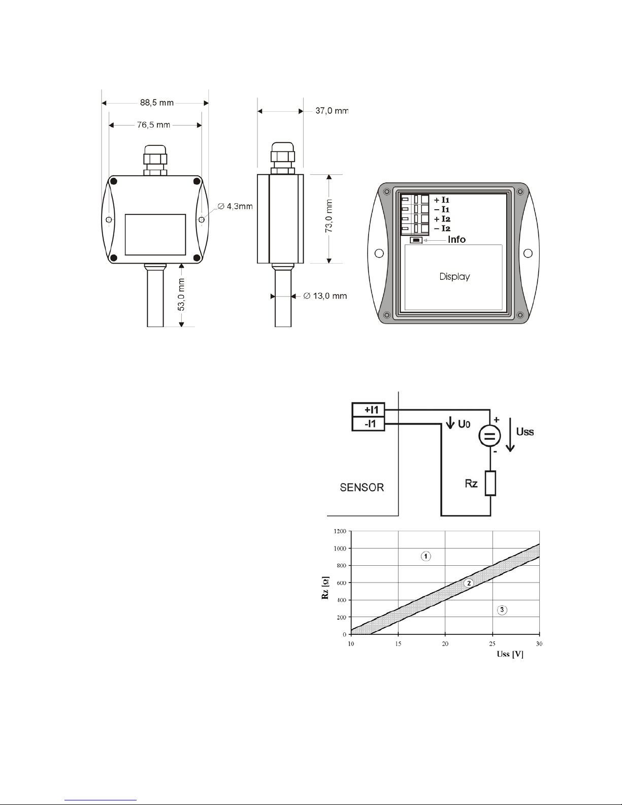
Transmitter is designed for wall mounting. There are two mounting holes at the sides of the
case. Don’t connect transmitter while power supply voltage is on. Interconnection terminals are
accessible after unscrewing four screws and removing the lid. Lace the cable through a gland at the
case wall. Connect the cable to terminals with respecting the signal polarity (see figure). Terminals
are self-clamping and can be opened by a suitable screwdriver. For the opening, insert the
screwdriver to upper terminal hole and lever by him. Do not remember to tighten glands and case
lid with inserted packing after cables connecting. It is necessary for warranting of protection IP65.
It is recommended to use shielded copper cable (e.g. SYKFY) with outside diameter of the
cable must be from 3.5 to 8 mm, maximal length 1200m. The cable must be located at indoor rooms
(probe is not protected for outdoor use). The cable should not be led in parallel along power
cabling. Safety distance is up to 0.5 m otherwise undesirable induction of interference signals can
appear.
In the application where air flow is too low it is possible that measurement accuracy may be a
bit lower (in decimals of °C) due to undesirable warm influence which develops in transmitter
electronics because of its own power dissipation. Mechanical construction of the transmitter and
working position is minimizing this effect, but in critical applications we recommend to use optimal
value of load resistor Rz (see graph no.2 below). It minimizes power dissipation to minimal value.
If Uss and Rz are set, it is possible to do it by inserting of suitable serial resistor into current loop at
estimation device side.
Electrical system (wiring) may do only worker with required qualification by rules in
operation.
Page 3
3
Dimensions
Typical application wiring
Calculation of minimum power voltage Uss for proper operation:
Uss min> Uo min+Imax*Rz,
where: Uo min= 9 V
Imax... approximately 20 mA
Rz... sensing resistor (shunt)
Choice of optimal power voltage and load
resistor for current loop.
area no 1.....transmitter doesn’t work correctly
area no 2.....optimal Uss and Rz
area no 3.....transmitter is working but it is
possible to see undesirable warm
influence.
Page 4
4
LCD Info mode
Several settings of installed transmitter are possible to verify without using computer. It is
necessary to connect at least power of current loop I1.
Unscrew the transmitter lid and shortly press button between display and interconnection
terminals by means of a tool (e.g. screwdriver).
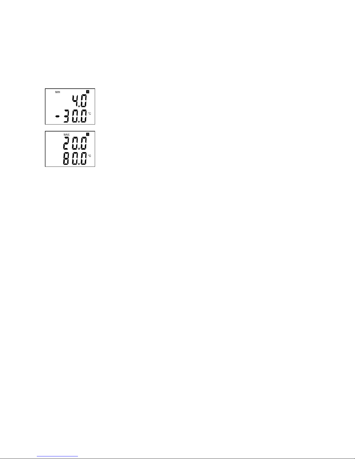
Range and type of value for output 1 (current loop I1 = symbol „1“ on
display). Type of value, assigned to output 1, is indicated by displayed unit
(here °C = temperature). Upper line displays current value corresponding to
measured value (lower line). Here 4 mA corresponds to -30 °C
Press button again to get value for upper point (same output, same value)
similarly as at previous point. Here 20 mA corresponds to 80 °C.
Press button again to end info mode and display actual measured values.
Notice: during info mode no measurement and no output current generation proceed. The
transmitter stays at info mode 15 s and then automatically goes back to measuring cycle.
Readings on LCD display
°C, °F
Reading next to this symbol is measured temperature or error state of value.
Technical parameters:
Analog output:
Current loop with range from 4 to 20 mA
Current output in case of error: <3.8 mA or >24 mA
Measuring parameters:
Ambient temperature (internal RTD sensor Pt1000/3850ppm):
Measuring range: -30 to +80 °C
Display resolution: 0.1 °C
Accuracy: ± 0.4 °C (For values on LCD display. For values on analog output too, if
selected output range is set inside measuring range).
Power: 9 to 30 V dc, maximum ripple 0.5 %
Response time (air flow approximately 1 m/s):
temperature: t90 < 4 min (temperature step 20 °C)
Recommended interval of calibration: 2 years
Measuring interval and LCD display refresh: 0.5 s
Communication with computer: via USB port by means of USB communication cable ATS-
AC02
Protection: IP65
Page 5

5
Operating conditions:
Operating temperature range: -30 to +80 °C, over +70°C switch LCD display OFF
Operating humidity range: 0 to 100 %RH
Outer characteristics in accordance with EN 33-2000-3:
normal environment with the specifications: AE1, AN1, BE1
Working position: the stem downwards
Electromagnetic compatibility: complies EN 61326-1
Not allowed manipulations:
It is not allowed to operate the device under other than specified conditions in technical
parameters. Devices are not designed for locations in chemically aggressive environment.
Storing conditions: temperature -30 to +80 °C, humidity 0 to 100 %RH without
condensation
Dimensions: 89 x 73 x 37 mm, stem length 53 mm
Weight: approximately 150 g
Material of the case: ABS
Procedure of modification of transmitter adjustment:
• device adjustment is performed by means of the optional ATS-AC02 communication
cable, connected to USB port of the PC.
• It is necessary to have installed configuration program Tsensor on the PC, It is free
available at Atal B.V.. During installation please take care about installation of driver
for USB communication cable
• Connect ATS-AC02 communication cable to the PC. Installed USB driver detect
connected cable and create virtual COM port inside the PC.
• Unscrew four screws of the device lid a remove the lid. If device is already installed to
measuring system, disconnect leads from terminals
• Connect ATS-AC02 communication cable to the device. Display must light up, or at
least must light up all symbols for one second (if LCD was switched OFF by program
before).
• Run installed Tsensor program and select corresponding communication COM port (as
described above).
• When new setting is saved and finished, disconnect the cable from the device, connect
leads into its terminals and place the lid back to the device.
Error states of the device
Device continuously checks its state during operation. In case error is found LCD displays
corresponding error code:
Error 0
First line displays „Err0“.
Check sum error of stored setting inside device’s memory. Output value is < 3.8 mA. This error
appears if incorrect writing procedure to device’s memory occurred or if damage of calibration data
appeared. At this state device does not measure and calculate values. It is a serious error, contact
distributor of the instrument to fix.
Error 1
Measured value is over upper limit of allowed full scale range. There is a reading „Err1“ on LCD
display. Output value is about 24.5 mA. This state appears if measured temperature is higher than
approximately 600°C (i.e. high non-measurable resistance of temperature sensor, probably opened
circuit).
Page 6

6
Error 2
There is a reading „Err2“ on LCD display. Output value is about 3.8 mA. Measured value is below
lower limit of allowed full scale range. This state appears if measured temperature is lower than
approximately -210°C (i.e. low resistance of temperature sensor, probably short circuit).
Error 3
There is a reading „Err3“ on LCD display upper line.
Error of internal A/D converter appeared (converter does not respond, probably damage of A/D
converter). No measurements proceed. Output value is about 3.8 mA. It is a serious error, contact
distributor of the instrument.
End of operation
Device itself (after its life) is necessary to liquidate ecologically!
Technical support and service
Technical support and service is provided by distributor.
Page 7

7
Notes:
 Loading...