

Page 1

1
Features
Real time detect, transmit and control indoor air quality
3-color TFT screen display and warning indoor CO2, TVOC, temperature and
relative humidity
Four buttons for operation conveniently
Two power supply optional for different application
Provide up to 3 analogs + 1 relay outputs or 3 relays + 1 analog outputs
Optional Modbus RS485 interface, to connect PC, realize remote control
Specification
Carbon Dioxide
Detecting gas
Carbon Dioxide (CO2)
Gas sensor
NDIR sensor
Accuracy@25℃(77℉)
±50ppm + 3% reading or ±75ppm (whichever is greater)
Stability
<2% of FS over lifetime (15 years) of sensor
Calibration
ABC Logic self-calibration
Lifetime of NDIR CO2 sensor
15 years (normal using)
Response time
<2 minutes for 90% step change
Renewed signal
Every 2 sec
Warm up time
2 hours (first time or using again after power off for a long time)
2 min (operation)
CO2 measuring range
0~2000ppm (default)
0~5000ppm (selected in the advanced setup)
CO2 display resolution
1ppm
TVOC
Sensing element
Japan Figaro semi-conductor mixed gas sensor
TVOC measuring range
0-30ppm
Temperature & Relative Humidity
Temperature sensor (selectable)
High precision digital integrated temperature and humidity sensor SHT,
or NTC thermistor
Measuring range
-20~60℃/-4~140F (default) 0~100%RH
Accuracy
Temp.: <±0.5℃@25℃ RH: <±3.0%RH (20%~80%RH)
Electrical Specification and Functions
Power supply
24VAC/VDC or 100-240VAC
Power consumption
5.5 W max. ; 2.5 W avg.
LCD screen
3-color TFT screen, with 4 buttons for operation
Output
Up to 3× analog + 1× relay outputs or 3× relay + 1× analog outputs
Analog: 0~10V or 4~20mA or PID
Relay: rated current: 5A, resistance load
CO2 Transmitter/Controller
Model: AT-VLX series
User Manual
Page 2
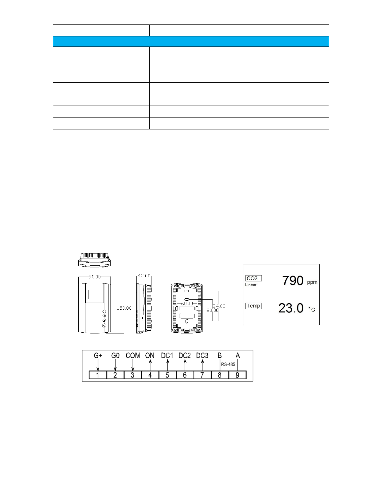
2
Fig. 1
Fig. 3
Fig. 2
Communication interface
MODBUS RS485
Operation Condition
Working condition
0~50℃; 0~95%RH, non-condensing
Storage condition
-10~60℃, 0~80%RH
Dimension/Weight
150mm(L)×90mm(W)×42mm(H)/280g
Installment standard
Wall type (65mm×65mm or 2”×4” wire box)
Housing and IP class
PC/ABS, IP class: IP30
Certification
EMC approval
Version
V.1711-S862
Mounting and Wire Connection
Notice the power supply of the monitor is 24VAC/VDC or 100~240VDC. Do not install the monitor on voltages higher
than marked on the monitor. Always turn off power before operating as follow steps.
Open the cover: push the both clips at the bottom of the unit, to remove the front cover from the back cover. Please
operate gently to avoid damaging of the clips.
Fix back cover: fix the back cover on the wall according to the dimension and position, see Fig. 1.
Connect wires: connect wires according to Fig.2 and press the wires under the terminals of back cover.
Close the cover: align the top clip of the unit firstly, then close the front cover and back cover by pressing the bottom
clips, to finish the installation.
Page 3

3
TFT Display & Buttons
There are TFT screen and 4 buttons on the cover, they are SET, ▲, ▼, and .
Power: used to turn on/off the transmitter/controller by each pressing. Under turning off station, OFF
displays on the right bottom corner, and under this station, all outputs are ineffective.
TFT display: CO2, temperature and humidity measuring value display on first line, second line and bottom line
respectively. If the output is linear, when customer press any key among SET, ▲, and ▼, it will display “Linear”
to indicate, the keys are in-effective, see below Fig. 3. TFT 3-color screen is controlled by CO2 measuring value,
with below default setpoint. End user can adjust the setpoint via Advanced Setup parameter P8 & P9.
│ Green: CO2 < 800ppm │ Yellow: 800ppm ≤ CO2 < 1200ppm │ Red: CO2 ≥ 1200ppm │
SET button: be used to switch parameter items and PID/relay set points. The parameter item switches to next by
each pressing, and will switch quickly by continuous pressing.
▲ & ▼: be used to adjust the setpoint/target value. The setpoint/target value only changes one by each pressing,
and will switch quickly by continuous pressing.
Lock/Unlock the buttons: Please refer to Advanced Parameter P72.
Table 1 - DIPs setting
ON
OFF
Default
DIP1
Advances Setup
Normal using
OFF
DIP2
AN3 output for TVOC
AN3 output for RH
OFF
DIPs Setting
End user can enter Advanced Setup by adjusting DIP1=ON and return to normal suing by adjusting DIP1=OFF.
DIP2 is used to adjust analog 3, when DIP2= ON, analog 3 is for TVOC, when DIP2=OFF, analog is for RH. See
above Table1.
Analog Output Setting
The default analog output is PID before leaving factory, unless otherwise stated by customers. End user can reset the
analog output as linear by Advanced Setup P20 according to below table 2. Voltage output or current output can be
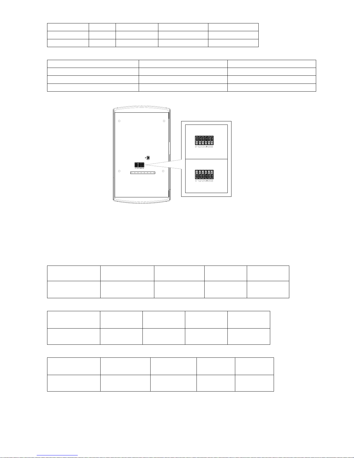
selected by connecting/disconnecting the jumpers, as shown on table 3 and Fig 4. End user also may get 2~10V or
4~20mA by adjusting parameters P22, P24, P26, P28, P30, P32, P34, P36 in Advanced Setup.
Table 2 – Analog linear/PID output instruction
Advanced
parameter
setting
P20 value
CO2
(DC1)
Temperature
(DC2)
RH
(DC3 DIP2=OFF)
TVOC
(DC3 DIP2=ON)
0
Linear
Linear
Linear
Linear
1
PID
Linear
Linear
Linear
2
Linear
PID
Linear
Linear
3
PID
PID
Linear
Linear
4
Linear
Linear
PID
Linear
5
PID
Linear
PID
Linear
6
Linear
PID
PID
Linear
7
PID
PID
PID
Linear
8
Linear
Linear
Linear
PID
9
PID
Linear
Linear
PID
10
Linear
PID
Linear
PID
11
PID
PID
Linear
PID
12
Linear
Linear
PID
PID
Page 4
4
13
PID
Linear
PID
PID
14
Linear
PID
PID
PID
15
PID
PID
PID
PID
Table 3 - Voltage output or current output selection via jumpers
DC1 for CO2
DC1 for temperature
DC1 for RH (or TVOC)
S5, S6 connect
S3, S4 connect
S1, S2 connect
Upper jumpers connect DC1=0~10V
Upper jumpers connect DC2=0~10V
Upper jumpers connect DC3=0~10V
Lower jumpers connect DC1=0~20mA
Lower jumpers connect DC2=0~20mA
Lower jumpers connect DC3=0~20mA
voltage output
0-10V
current output
0-20mA
Relay Control Mode
End user may adjust CO2 relay 1 control mode by Advanced Setup P12 as instructed by below table 4, adjust
temperature relay 2 control mode by Advanced Setup P13 as instructed by table5, adjust humidity relay 3 control
mode (DIP2=OFF) by Advanced Setup P14 as instructed by table 6, adjust TVOC relay 3 control mode (DIP2=ON) by
Advanced Setup P15 as instructed by table 7.
Table 4 CO2 relay 1 control mode
Advanced parameter
P12 value
1 2 3
4
Function
Auto control
ON1- decrease CO2
Auto control
ON1- increase CO2
Manual control
ON1- OFF
Manual control
ON1 -ON
Table 5 Temperature relay 2 control mode
Advanced parameter
P13 value
1 2 3
4
Function
Auto control
ON2-cooling
Auto control
ON2-heating
Manual control
ON2- OFF
Manual control
ON2 -ON
Table 6 Humidity relay 3 control mode (DIP2=OFF)
Advanced parameter
P14 value
1
2
3
4
Function
Auto control
ON3- dehumidifying
Auto control
ON3- humidifying
Manual control
ON3- OFF
Manual control
ON3 -ON
Fig. 4
Page 5

5
Table 7 TVOC relay 3 control mode (DIP2=ON)
Advanced parameter
P15 value
1 2 3
4
Function
Auto control
ON3- decrease TVOC
Auto control
ON3- increase TVOC
Manual control
ON3- OFF
Manual control
ON3 -ON
For example, End user may adjust the CO2 relay offset by Advanced Setup parameters P16. The relay 1 auto control
logic is as below instructed:
a. under decrease CO2 mode, when CO2 measuring > CO2 setpoint, relay 1 = ON, when CO2 measuring ≤ CO2
setpoint – CO2 offset, relay 1 = OFF
b. under increase CO2 mode, when CO2 measuring < CO2 setpoint, relay 1 = ON, when CO2 measuring ≥ CO2
setpoint + CO2 offset, relay 1 = OFF
c. under CO2 manual control-OFF, relay 2 = OFF
d. under CO2 manual control-ON, relay 2 = ON
Advanced Setup
After power off and remove the back cover, there is a set of DIPs on the middle part of PCB. Put the DIP1 to ON to
enter Advanced Setup interface, and put the DIP1 back to OFF, it will return back to normal using interface. Using SET
button to switch the parameter items from P1 to P75, and using ▲ & ▼ buttons to adjust the target values.
Wait 6 seconds for the new value to set!
Note: Please read the below parameters firstly, any of modification do not be recommended if not necessary.
Parameter
Setting range
Default
P1
Device RS485 address
1~247
1
P2
RS485 baud rate
4800 9600 14400 19200 38400 56000 57600 115200
9600
P3
RS485 parities and stops
choice
1-1stop bit None;2-2stop bit None;3-1stop bit ODD;
4-1stop bit EVEN
1
P4
CO2 correction value
-300 ~ 300 ppm
0
P5
Temp correction value
-5.00 ~ 5.00℃
0.00
P6
Humidity correction value
-5.00 ~ 5.00 %RH
0.00
P7
TVOC correction target value
0.0 ~ 30.0ppm
15.0
P8
CO2 green to yellow setpoint
1 ~ 5000ppm
800
P9
CO2 yellow to red setpoint
1 ~ 5000ppm
1200
P10
TVOC green to yellow setpoint
0.0 ~ 30.0ppm
10.0
P11
TVOC yellow to red setpoint
0.0 ~ 30.0ppm
20.0
P12
The relay mode for CO2
1 ~ 4 (see table 4)
1
P13
The relay mode for Temp
1 ~ 4 (see table 5)
1
P14
The relay mode for Humi
1 ~ 4 (see table 6)
1
P15
The relay mode for TVOC
1 ~ 4 (see table 7)
1
P16
CO2 offset for relay control
1 ~ 5000ppm
10
P17
Temp offset for relay control
-20.0 ~ 60.0℃
1.0
P18
Humi offset for relay control
0.01 ~ 100.00 %RH
1.0
P19
TVOC control relay offset
0.0 ~ 30.0ppm
1.0
P20
PID or Linear output
0 ~ 15 (see table 3)
15
P21
CO2 linear min value
0 ~ 5000ppm
0
P22
CO2 linear min volt
0.000 ~ 10.000V, configure current output by current
value/2
0.000
P23
CO2 linear max value
0 ~ 5000ppm
2000
P24
CO2 linear max volt
0.000 ~ 10.000V, configure current output by current
10.000
Page 6

6
value/2
P25
Temp linear min value
0~50℃
0.0
P26
Temp linear min volt
0.000 ~ 10.000, configure current output by current
value/2
0.000
P27
Temp linear max value
0~50℃
50.0
P28
Temp linear max volt
0.000 ~ 10.000V, configure current output by current
value/2
10.000
P29
Humi linear min value
0.01 ~ 100.00%RH
0.0
P30
Humi linear min volt
0.000 ~ 10.000V, configure current output by current
value/2
0.000
P31
Humi linear max value
0.01 ~ 100.00%RH
100.0
P32
Humi linear max volt
0.000 ~ 10.000V, configure current output by current
value/2
10.000
P33
TVOC linear min value
0.0 ~ 30.0ppm
0.0
P34
TVOC linear min volt
0.000 ~ 10.000V, configure current output by current
value/2
0.000
P35
TVOC linear max value
0.0 ~ 30.0ppm
30.0
P36
TVOC linear max volt
0.000 ~ 10.000V, configure current output by current
value/2
10.000
P37
CO2 PID period setpoint
0.1 ~ 10000.0
0.1
P38
CO2 PID-P setpoint
-10000 ~ 10000
-2.0
P39
CO2 PID-I setpoint
0.0 ~ 10000.0
40.0
P40
CO2 PID-D setpoint
0.0 ~ 10000.0
10.0
P41
Temp PID period setpoint
0.1 ~ 10000.0
0.1
P42
Temp PID-P setpoint
-10000 ~ 10000
-2.0
P43
Temp PID-I setpoint
0.0 ~ 10000.0
40.0
P44
Temp PID-D setpoint
0.0 ~ 10000.0
10.0
P45
Humi PID period setpoint
0.1 ~ 10000.0
0.1
P46
Humi PID-P setpoint
-10000 ~ 10000
-2.0
P47
Humi PID-I setpoint
0.0 ~ 10000.0
40.0
P48
Humi PID-D setpoint
0.0 ~ 10000.0
10.0
P49
TVOC PID period setpoint
0.1 ~ 10000.0
0.1
P50
TVOC PID-P setpoint
-10000 ~ 10000
-2.0
P51
TVOC PID-I setpoint
0.0 ~ 10000.0
40.0
P52
TVOC PID-D setpoint
0.0 ~ 10000.0
10.0
P53
CO2 PID MAN ON setpoint
0 ~ 1
0
P54
CO2 PID MAN setpoint
0 ~ 100 % 0~10v/0~20mA percent
Not confirm
P55
Temp PID MAN ON setpoint
0 ~ 1
0
P56
Temp PID MAN setpoint
0 ~ 100 % 0~10v/0~20mA percent
Not confirm
P57
Humi PID MAN ON setpoint
0 ~ 1
0
P58
Humi PID MAN setpoint
0 ~ 100 % 0~10v/0~20mA percent
Not confirm
P59
TVOC PID MAN ON setpoint
0 ~ 1
0
P60
TVOC PID MAN setpoint
0 ~ 100 % 0~10V/0~20mA percent
Not confirm
P61
CO2 PID self-tuning
1- Run CO2 control PID self-tuning
0- stop PID self-tuning
0
P62
Temp PID self-tuning
1- Run temp. control PID self-tuning
0- stop PID self-tuning
0
P63
Humi PID self-tuning
1- Run humi. control PID self-tuning
0- stop PID self-tuning
0
Page 7
7
P64
TVOC PID self-tuning
1- Run TVOC control PID self-tuning
0- stop PID self-tuning
0
P65
Power on again
1- turn off
2-turn on after power up again
3- hold the mode before the power failure
3
P66
Temperature unit
1- Degree Celsius; 2- Fahrenheit
1
P67
CO2 ABC Logic
1- ABC Logic ON;
2- ABC Logic OFF; (T67X3 only can set, cannot
read)
0
P68
CO2 elevation setpoint
0 ~ 5000ppm feet
0
P69
CO2 single-point calibration
target
0 ~ 5000ppm S8 does not support this command
400
P70
CO2 single-point calibration
on/off
0- do not run single calibrate
1- start to run single calibrate
0
P71
TVOC AD adjustment
-500 ~ 500 (TVOC AD calibration value)
0
P72
Disable/enable buttons
1- all buttons are usable; 2- ON/OFF button disable;
3- set, ▲,▼buttons disable; 4- all buttons disable
2
P73
relay and analog output test
0- DC1 DC2 DC3 ON1 ON2 ON3 run normally
1- DC1=0V/0mA DC2=0V/0mA DC3=0V/0mA
ON1=OFF ON2=OFF ON3=OFF
2- DC1=2V/4mA DC2=2V/4mA DC3=2V/4mA
ON1=OFF ON2=OFF ON3=OFF
3- DC1=10V/20mA DC2=10V/20mA DC3=10V/20mA
ON1=ON ON2=ON ON3=ON
0
P74
CO2 range
0~5000ppm
2000
P75
Firmware version
862
862
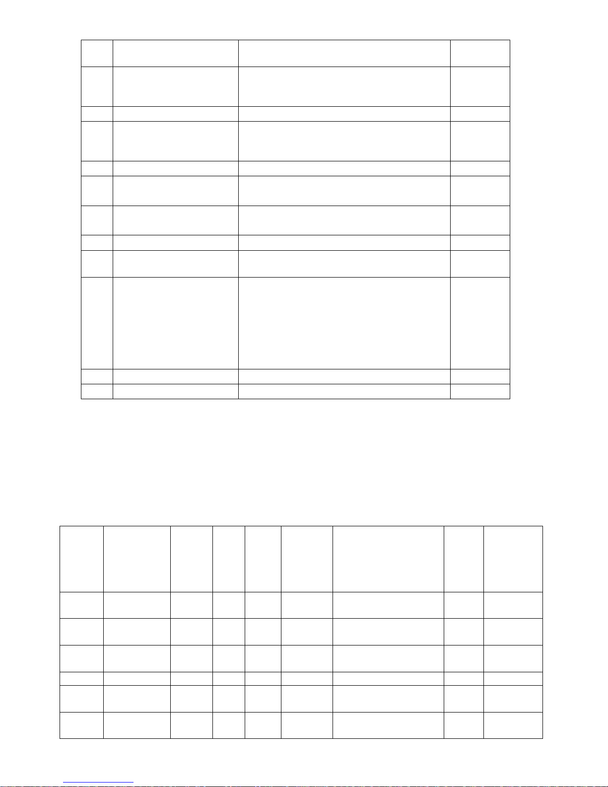
Modbus Parameters
Mode: RTU (MSB First)
Baud Rate: 9600,14400,19200,38400,56000,57600,76800,115200bps default: 9600
Start Bits: 1
Data Bits: 8
Stop Bits: 1 / 2 default : 1
Parity: None / Odd / Even default: None
Register Map Support Function: 3 4 6 16
Starting
Register
Decimal
Address
(Base 0)
Data
Description
Function
Read/
Write
Length
Format
Valid Response
Default
Correspond
LCD
Parameter
0
ON1-Relay1
output
1 R 1
UINT8
0-OFF;1-ON
1
ON2-Relay2
output
1 R 1
UINT8
0-OFF;1-ON
2
ON3-Relay3
output
1 R 1
UINT8
0-OFF;1-ON
0
Co
Measurement
4 R 2
Float
Big-endian
0~5000 ppm
2
Temp.
Measurement
4 R 2
Float
Big-endian
0.0~50.0℃/32.0~122.0℉
Page 8

8
4
Humi.
Measurement
4 R 2
Float
Big-endian
0.1~100.0 RH%
6
TVOC
measurement
4 R 2
Float
Big-endian
0~30.0ppm
94
DC1 0-10v
4-20mA
analog output
4 R 2
Float
Big-endian
0.0~10V/4~20mA
96
DC2 0-10v
4-20mA
analog output
4 R 2
Float
Big-endian
0.0~10V/4~20mA
98
DC3 0-10v
4-20mA
analog output
4 R 2
Float
Big-endian
0.0~10V/4~20mA
0
RS485 Device
MAC address
3/6
R/W 1 UINT16
1~247
1
P-1
1
RS485 baud
rate choice
3/6
R/W 1 UINT16
2-9600bps; 3-14400bps
4-19200bps; 5-38400bps
6-56000bps; 7-57600bps
8-76800bps; 9-115200bps
2
P-2 2 RS485 parities
and stops
choice
3/6
R/W 1 UINT16
1-None 1Stop Bit;
2-None 2Stop Bit;
3-Odd 1Stop Bit;
4-Even 1Stop Bit
1
P-3 4 All button lock
choice
3/6
R/W 1 UINT16
1- all buttons are usable
2- ON/OFF button disable
3- set, ▲,▼buttons disable
4- all buttons disable
1
P-72
10
Co2 setpoint
3/16
R/W 2 Float
Big-endian
0~5000ppm
800
User “Co2
setpoint”
12
Temp setpoint
3/16
R/W 2 Float
Big-endian
-20.0~60.0
25
User “Temp
setpoint”
14
Humi setpoint
3/16
R/W 2 Float
Big-endian
0~100%RH
50
User “Humi
setpoint”
16
TVOC setpoint
3/16
R/W 2 Float
Big-endian
0~30.0ppm
15
User “TVOC
setpoint”
7
Device Turn
On/Off
3/6
R/W 1 UINT16
0-TurnOn; 1-TurnOff
0
User “power”
button
26
CO2 adjust
value
3/16
R/W 2 Float
Big-endian
-300~300.0ppm
0.0ppm
P-4
28
Temp. adjust
setpoint
3/16
R/W 2 Float
Big-endian
-3.0~3.0℃
0.0℃
P-5
30
Humi. adjust
setpoint
3/16
R/W 2 Float
Big-endian
-5.0~5.0%RH
0.0
%RH
P-6
32
TVOC adjust
target setpoint
3/16
R/W 2 Float
Big-endian
0~30ppm
0.0
%RH
P-7
Note:Scan Rate>=4000ms
 Loading...