

Page 1
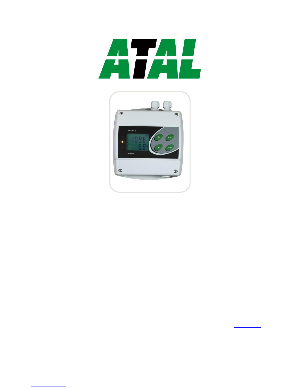
AT-VLS-101DE
Manual
ATAL B.V.
Ampèrestraat 35-37
NL-1446 TR PURMEREND
Postbus 783
NL-1440 AT PURMEREND
T (+31) 0299 630 610
F (+31) 0299 630 611
I www.atal.nl
Page 2

2
PRODUCT DESCRIPTION
Programmable regulators with Ethernet connection are designed to measure temperature and relative humidity of air, to measure
concentration of CO2 in the air, to signal alarms and control of external devices. Regulators can be used in a chemically nonaggressive environment.
The CO2 concentration is measured using the maintenance free sensor. The unique patented auto-calibration procedure
compensates aging of the sensing element and guarantees outstanding high reliability and long-term stability.
The function of two output relays can be set using the device keyboard or from computer. It is possible to assign any input or
computed value (dew point temperature, absolute humidity, specific humidity mixing ratio and specific enthalpy) to each relay.
Setting of delay, hysteresis, audible alarm is enabled for each relay and it is possible to control output relay status via Ethernet too.
The instrument may send a warning message if the measured value goes out of adjusted limits. Devices are equipped with four
button keyboard and two-line LCD display. The visual indication of the concentration of CO2 is provided by three LEDs to the left
side of the display.
The supported Ethernet communication formats: www pages with user-design possibility, Modbus TCP protocol, SNMPv1
protocol and SOAP. For setting of all parameters you can use TSensor software.
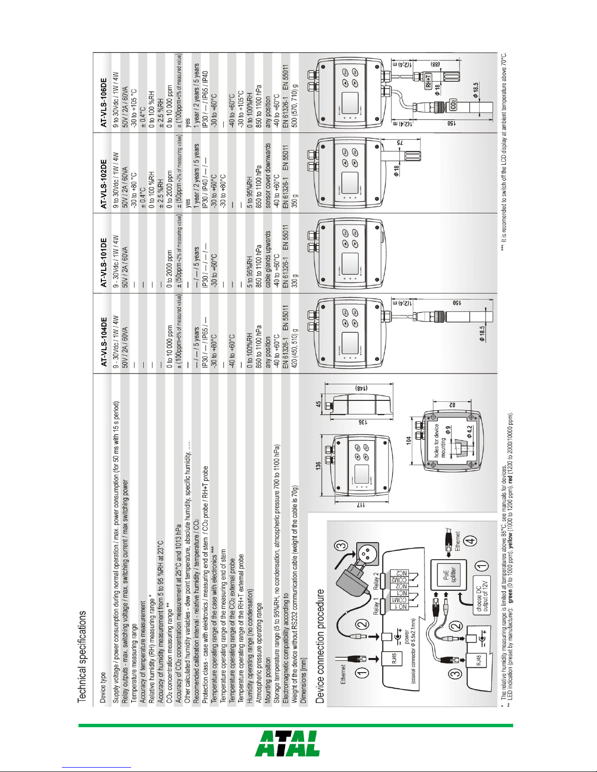
type * measured values version mounting
AT-VLS-104DE CO
2
probe on cable wall
AT-VLS-101DE CO2 ambient air wall
AT-VLS-102DE T + RH + CO2 + CV ambient air wall
AT-VLS-106DE T + RH + CO2 + CV probes on cable wall
f
* T…temperature, RH…relative humidity, CO2…concentration CO2 in air, CV…computed values
INSTALLATION , OPERATION AND CONFIGURATION
The mounting holes and connection terminals are accessible after unscrewing the four screws in the corners of regulator and
removing the lid. Devices have to be mounted on a flat surface to prevent deformation. For output relays connection choose cables
with external diameter 4 to 6.5mm and wire cross-section 0.14 to 1.5mm2. Do not forget to insert attached plugs into unused cable
glands. Unpack the external CO2 probe and connect it to the regulator. Pay attention to mounting the device and probes, because
incorrect choice of working position or place of measuring could adversely affect accuracy and long-term stability of measured
values.
Actual parameters settings of each relay can be displayed by pressing of „ ▲“ key. To change any parameter, press the „Set“ key,
enter password (default 0000) and set required value. Then click on „Set“ and pressing „Esc“ key exit setup mode. To change the
password and to set all other parameters (acoustic alarm, limits of CO2 indication, computed value selection etc.) is used Extended
setting mode.
For network device connection it is necessary to know new suitable IP address (you can get it automatically from DHCP server or
from your network administrator) and to have TSensor software installed. After you connect Ethernet cable, power adapter or PoE
splitter, you run TSensor program, set the new IP address, configure the device in accordance with your requirements and finally
store the settings. The default IP address of each device is preset to 192.168.1.213.
After switching the device starts internal test. During this time (about 20 s) LCD display shows ---- instead of CO2 concentration
value.
Devices don´t require special maintenance. We recommend you periodical calibration for validation of measurement accuracy.
ERROR STATES
Device continuously checks its state during operation and if an error appears, it is displayed relevant code: Err 1 – measured value
(except of CO2 concentration) or calculated value is over the upper limit, Err 2 – measured or calculated value is below the lower
limit or concentration CO2 measurement error occurred, Err 0, Err 3 and Err 4 – it is a serious error, please contact distributor of
the device, Err 5, Err 6 - there is problem with assigned value to output relay, Err 9 – inserted password is not valid.
SAFETY INSTRUCTIONS
- Humidity and temperature sensors of the regulator cannot be operate and store without a filter cap.
- Temperature and humidity sensors have not to be exposed to direct contact with water and other liquids.
- It is not recommended to use the humidity regulators for long time under condensation conditions.
- Take care when unscrewing the filter cap as the sensor element could be damaged.
- The regulator must be turned on for at least 24 hours in order to start the automatic calibration of the CO2
sensor.
- Use only the power adapter according to technical specifications and approved according to relevant
standards.
- Don’t connect or disconnect devices while power supply voltage is on.
- Installation, electrical connection and commissioning should be performed by qualified personnel only.
- Devices contain electronic components, it needs to liquidate them according to currently valid conditions.
Page 3
3
 Loading...