

Page 1
Page 2
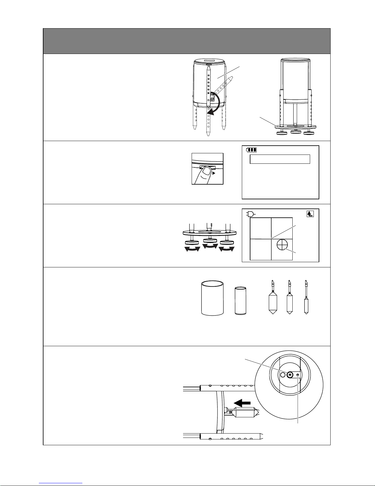
Quick Manual
(using L Beaker as an example)
1. Setup (
C
p.9)
① Rotate the main unit's legs and
position it upright.
② Place the main unit on the stand.
2. Power ON (
C
p.10)
① Push the dial button (for at least 0.5
seconds).
The main menu screen will be
displayed.
3. Level Check (
C
p.12)
① Use the screws at the base of the
stand to adjust the level. Align the
mark with the center of the screen.
4. Spindle and Beaker Selection
(
C
from p.42)
① Refer to the "Maximum
Measurement Values Guideline
Chart" and select the most suitable
spindle and beaker for your
application.
5. Spindle and Temperature
Sensor Preparation
(
C
from p.14)
① Attach the spindle and the
temperature sensor to the main unit.
20.0°C
Measu r e m e nt
Level
Auto S t o p
User S c a l e
Setup
Beaker Spindle
20.0°C
Center
Mark
Shaft holder
Temperature sensor
attachment point
Main unit
Stand
Page 3
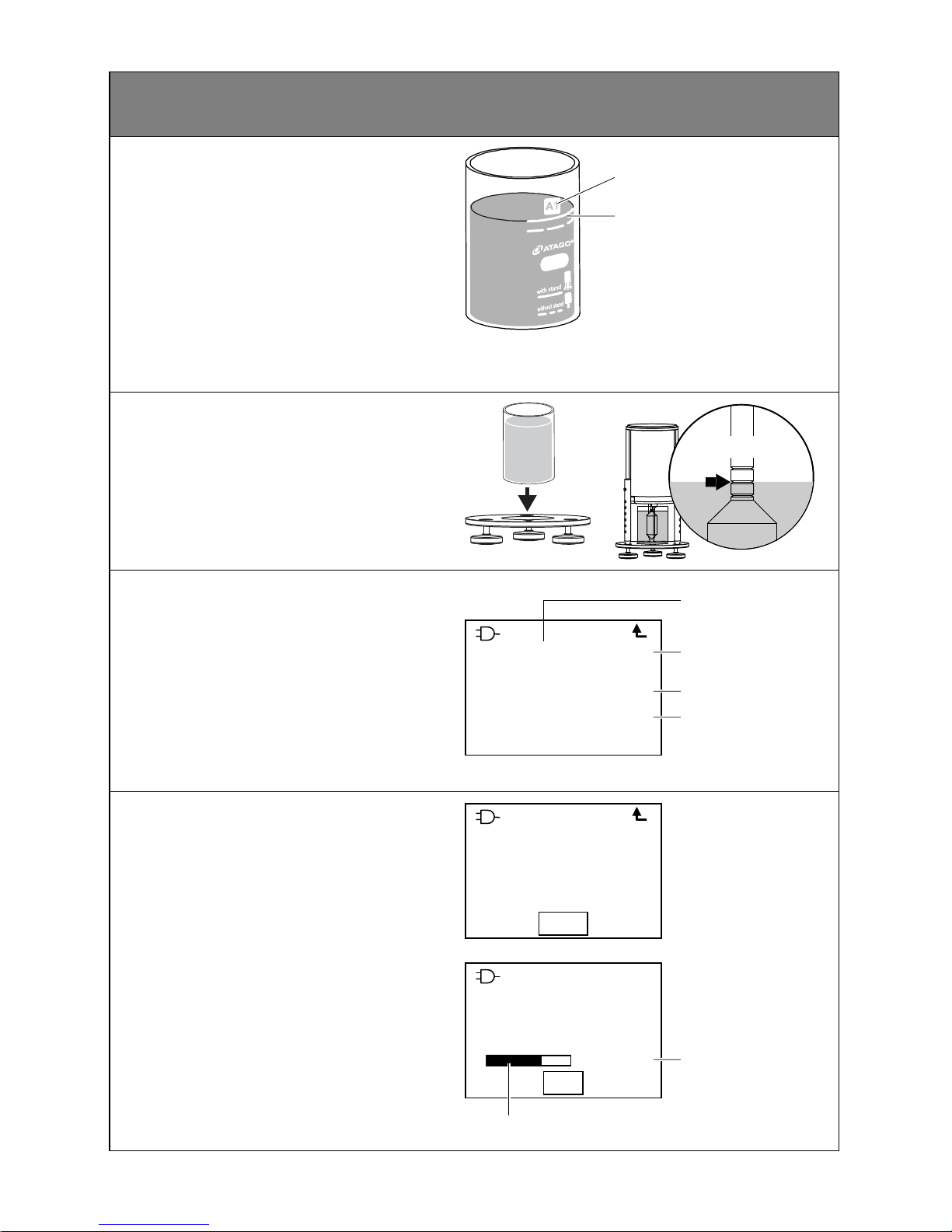
Quick Manual
(using L Beaker as an example)
6. Sample Preparation (
C
p.15)
① Pour the sample in the beaker.
N Reference lines may not be present on
some beakers.
7. Beaker Setup (
C
p.16)
① Attach the beaker to the stand.
② Place the main unit on the stand.
③ Check that the surface of the
sample is level with the spindle's
reference line.
8. Settings (
C
p.17)
① Set the spindle/beaker type and
speed.
N For your convenience,
"Auto Stop" (Cp.25)
"User Scale" (Cp.27) ,and
"Moving Average" (Cp.33)
functions are available.
9. Measurement (
C
p.18)
① Select "Start" to begin
measurement.
Measurement values will be
displayed.
② Select "Quit" to terminate
measurement.
N Cleaning (Cp.24)
N Basic Settings (Cp.31)
Reference line
Spindle name
Reference line (solid line)
For normal measurement use
20.0°C
-- A1L 200.0 r p m
558.2
mPas
67.4%
Quit
Torque % bar
Torque %
20.0°C
-- A1L 100.0 r p m
0.0
mPas
Max: 1,657 m P a s
Start
20.0°C
-- A1L 100.0 r p m
0.0
mPas
Max: 1,657 m P a s
Start
Speed setting
Spindle/beaker
setting
Viscosity
Max viscosity
value
Page 4
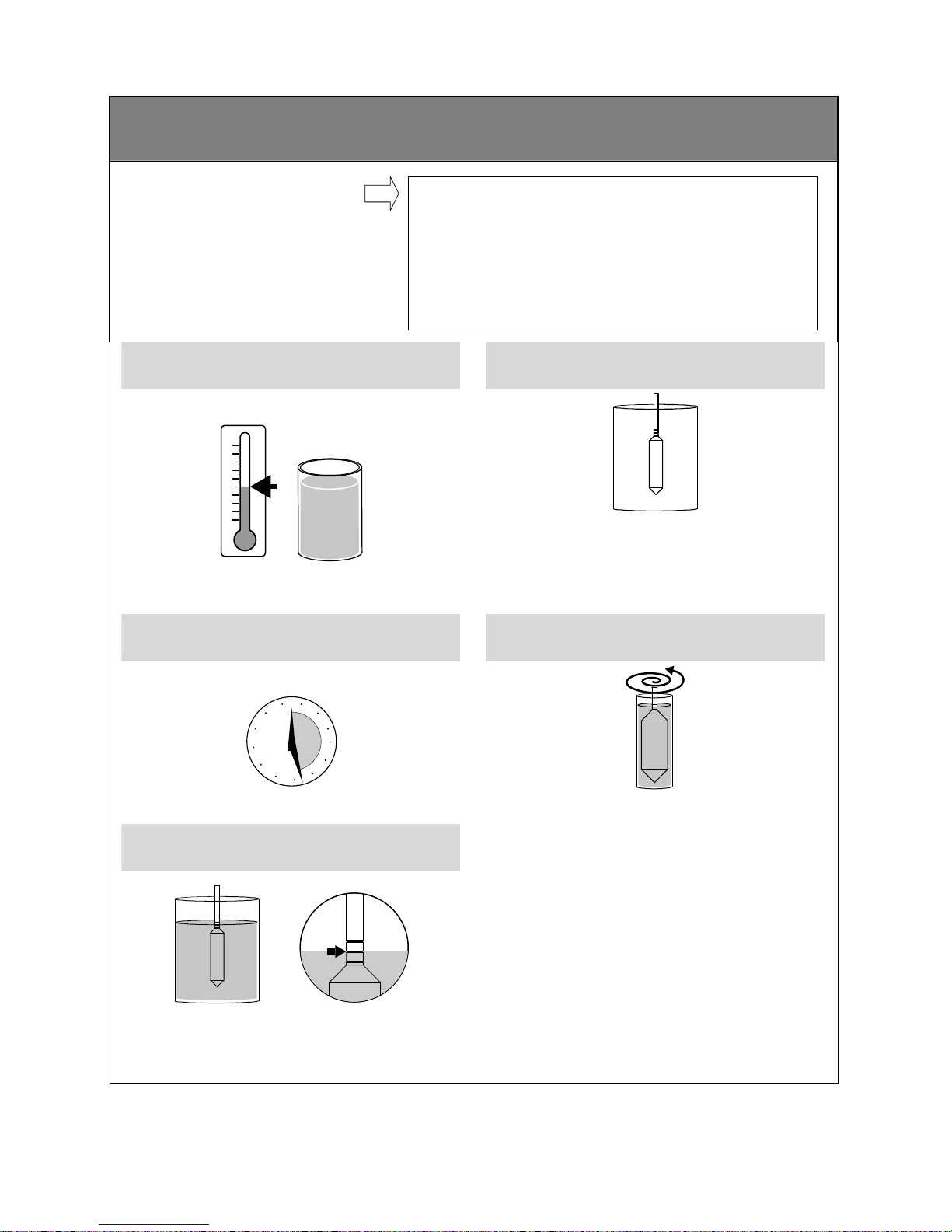
Measurement Tips
Sample Temperature
Spindle and Beaker Combination
N Measurement values may differ
depending on the distance
between the spindle and the
beaker.
Measurement Time
Speed
Sample Amount
N Check that the surface of the
sample is level with the spindle's
reference line.
Reference line
For stable measurement values, always
perform measurements under the same
conditions.
Changes in viscosity may occur due to
varying conditions.
How can I obtain stable
measurement values?
Page 5
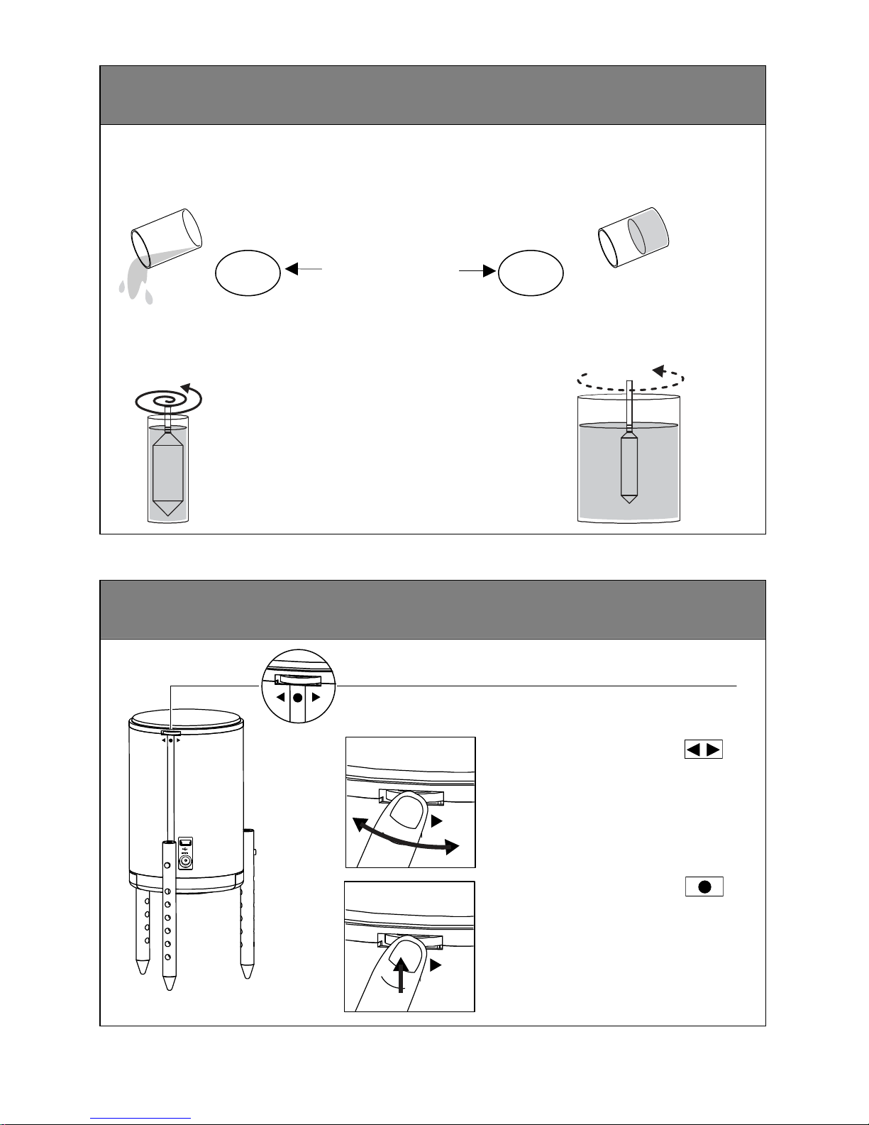
Measurement Tips
Which beaker and spindle should I choose?
Which speed setting should I select?
Dial Button Operation
Slide (will be indicated by
throughout this manual)
Slide the dial button to change
settings and item selections.
Push (will be indicated by
throughout this manual)
Push the dial button to power the
instrument ON/OFF.
Use to confirm settings and item
selections.
Posterior Illustration
Dial button
Operation
Sample Viscosity
Hi g h e r ・・・ ・ ・・・ ・ S p eed ・ ・ ・・・ ・ ・ ・L o w e r
Wider・ ・ ・ ・ ・ ・ ・ ・ S p indle ・ ・ ・ ・ ・ ・ T h i nner
1 5 m L ・ ・ ・ ・ ・・ ・ ・ B ea k er ・ ・ ・ ・ ・・ 1 0 0 mL
Low
High
The sample does not
readily
dribble out even when
turned upside-down.
Page 6

1
CONTENTS
1 Introduction............................................................................................................................. 3
1-1 Important Information............................................................................................................3
1-2 Safety Information ..................................................................................................................3
1-3 Precautions................................................................................................................................6
2 Instrument ............................................................................................................................... 7
2-1 Content........................................................................................................................................7
2-2 Names and Functions of Components...........................................................................7
2-3 Inserting the Batteries (when using batteries as a power source)....................9
2-4 Setup ............................................................................................................................................9
2-5 Power ON/OFF........................................................................................................................10
2-6 Displays .......................................................................................................................................11
2-7 Level Check...............................................................................................................................12
3 Measurement.......................................................................................................................... 13
3-1 Measurement Screen.............................................................................................................13
3-2 Measurement Procedures ...................................................................................................14
3-2-1 Spindle Preparation .................................................................................................14
3-2-2 Temperature Sensor Preparation......................................................................15
3-2-3 Sample Preparation .................................................................................................15
3-2-4 Beaker Setup .............................................................................................................16
3-2-5 Spindle/Beaker Settings .......................................................................................17
3-2-6 Speed Settings ..........................................................................................................17
3-2-7 Measurement..............................................................................................................18
3-3 Computer Output ....................................................................................................................19
3-3-1 Driver Installation .....................................................................................................19
3-3-2 Computer - Data Setting......................................................................................21
3-3-3 Data Output From Instrument to PC...............................................................22
3-3-4 Saving Data and Disconnecting..........................................................................23
4 Cleaning .................................................................................................................................... 24
4-1 Main Unit.....................................................................................................................................24
4-2 Spindles .......................................................................................................................................24
5 Error Messages ..................................................................................................................... 24
6 Auto Stop................................................................................................................................. 25
6-1 Screen Display..........................................................................................................................25
6-2 Auto Stop ON/OFF and Setting Value Input..............................................................26
7 User Scale............................................................................................................................... 27
7-1 Preparation ................................................................................................................................27
7-2 Creating a User Scale ...........................................................................................................28
7-2-1 Screen Display...........................................................................................................28
7-2-2 Viscosity Input...........................................................................................................29
7-2-3 User Scale ON/OFF and Scale Number Settings......................................30
8 Basic Settings (setup)........................................................................................................ 31
8-1 Setup Screen............................................................................................................................31
Page 7

2
8-1-1
Language ......................................................................................................................31
8-1-2 Unit Display.................................................................................................................31
8-1-3 Date/Time ...................................................................................................................32
8-1-4 Brightness....................................................................................................................32
9 Moving Average..................................................................................................................... 33
9-1 Moving Average ON/OFF ....................................................................................................33
10 User Calibration .................................................................................................................... 34
10-1 Troubleshooting Tips .............................................................................................................34
10-2 User Calibration .......................................................................................................................35
10-2-1 Display .........................................................................................................................35
10-2-2 Spindle/Beaker Settings......................................................................................36
10-2-3 Standard Liquid Viscosity Settings.................................................................36
10-2-4 Performing User Calibration...............................................................................37
10-3 Restore Default Calibration Settings..............................................................................38
11 Abnormal Measurement Values ..................................................................................... 39
12 Optional Accessories and Replacement Parts ....................................................... 41
13 Supplementary Material..................................................................................................... 42
13-1 Maximum Measurement Values Guideline Chart .......................................................42
14 Warranty, Repair and Calibration................................................................................... 44
15 Specifications......................................................................................................................... 45
Page 8
3
1 Introduction
1-1 Important Information
Thank you for purchasing VISCO/VISCO-895. Before using the instrument, read this
instruction manual carefully. Keep this manual on hand for future reference.
Pay particular attention to the "Safety Information" section, as understanding the contents
is necessary for safe operations.
1-2 Safety Information
Please read and understand the following safety instructions to ensure safe use of the
instrument. Failure to do so could result in injury and/or damage. The definitions of the icons
and symbols can be found below.
Explanation of Icons
WARNING
If this indication is neglected and the instrument is handled incorrectly,
serious injury and death may result.
CAUTION
If this indication is neglected and the instrument is handled incorrectly,
injury and damage to one's property may result.
Explanation of Symbols
This symbol denotes an item that you are warned or cautioned of (a warning
item). The contents are described in detail in or near the △.
This symbol denotes an action that must not be performed (a prohibited item).
The contents are described in detail in or near the ○.
This symbol denotes an action that must be performed (an action item).
The contents are described in detail in or near the ●.
Page 9

4
Instrument Handling and Maintenance
WARNING
• When measuring a substance harmful to
the human body, be well aware of its
properties and wear protective gloves,
mask, etc.
• If the instrument begins to smell
abnormally, overheat, or emit smoke,
turn off the power switch and disconnect
the power plug immediately. Continued
use of the instrument may result in fire
or malfunction. Contact your ATAGO
distributor for an inspection.
• Do not attempt to repair, modify, or
disassemble the instrument yourself.
Improper servicing may result in fire,
electrical shock, or burns.
• If the instrument is dropped or is
subjected to a strong shock, contact
ATAGO or an Authorized ATAGO
Service Center nearby for an inspection.
Continued use of the instrument may
result in fire or malfunction.
CAUTION
• Do not apply water or sample over any
part of the instrument. This may result in
a malfunction.
• Always turn off the power switch after
use.
• When transporting the instrument, place
it in its original box. Always attach the
protective cap to the shaft holder.
• Do not place excessive force or undue
stress on the shaft holder. This may
cause damage to the shaft holder.
• Carefully read this instruction manual and fully understand the function and operation of
each part of the instrument before use.
• Check that each part of the instrument operates normally before use.
• Perform the necessary operation checks, such as calibration, according to the instruction
manual.
• ATAGO shall not be held responsible for any or all damages as a result of use of the
instrument for those other than its intended purposes (viscosity measurement of liquid
samples).
• ATAGO shall not be held responsible for any or all undesired effects on the consumption or
application of the measured materials that may occur as a result of use of the instrument.
• Only use the specified battery type. Observe proper polarities, properly aligning the anodes
and cathodes.
• Remove the batteries and store them in the carrying case during air transport.
Page 10

5
Plug Handling and Maintenance
WARNING
• Be sure to use the AC adapter included
with the instrument. If an AC adaptor
other than the one included is used, the
rated voltage and polarity of the power
may be different and may cause smoke
or fire.
• Do not insert the plug of the AC adapter
in an outlet other than AC100 to 240V.
Inserting the plug in any other outlet may
result in short circuiting the instrument,
smoke or fire.
• Do not use the AC adapter if damaged or
broken. Using a damaged AC adapter
may result in fire, electrical shock, or
burns.
CAUTION
• Do not insert or disconnect the plug with
wet hands.
• Be sure to hold and gently pull the plug
when disconnecting the cable from the
outlet. Yanking or pulling the cable
improperly may damage the plug and
result in fire or electrical shock.
Page 11

6
1-3 Precautions
Ambient Conditions
• Use the instrument at an altitude below 2,000 m (above sea level).
• Use the instrument indoors.
• Use the instrument on a flat and level surface such as a desk or table.
• Use the instrument where the temperature is between 10 to 40˚C.
• Do not leave the instrument in a location exposed to direct sunlight or near a heating
unit where the temperature may rise.
• Do not expose the instrument to sudden temperature changes.
• Do not place the instrument in a place where it may be subject to strong vibrations.
• Do not use the instrument where there is much dust.
• Do not leave the instrument where the temperature is extremely low.
• Do not leave the instrument in a humid place.
• Do not place or drop heavy objects on the instrument.
• Use the instrument under temperature conditions where relative humidity is 80% at 31˚C
or lower, decreasing linearly to 50% at 40˚C.
• Main power supply voltage fluctuation should not exceed ±10% of the nominal voltage.
• Transient voltage: IEC Installation Category (Overvoltage Category) ll
• Pollution degree: 2 (IEC60664)
Handling
• Do not drop the instrument or subject it to any strong shock.
• Cables may be damaged if mishandled in any of the following manner:
• Bending the cable.
• Pulling the cable.
• Placing the cable under heavy objects.
• Placing the cable between heavy objects.
Daily Maintenance
• Thoroughly clean the spindles, beakers and temperature sensor, then dry them well.
• If the instrument becomes dirty, wipe with a soft cloth.
• Do not use benzine, paint thinner, etc. to clean the instrument.
Page 12
7
2 Instrument
2-1 Content
Main unit................................................................1
Stand.......................................................................1
Spindles (A1, A2 and A3)..............one each
Temperature sensor.........................................1
Small volume beaker attachment...............1
S Beaker (15mL) .............................. 1
L Beaker (100mL) ............................ 1
AC adapter.......................................... 1
USB Mini-B cable (1m) ................. 1
1.5V AA alkaline batteries............ 4
Instruction manual (this book) ... 1
Inspection certificate ..................... 1
Spindle stand ..................................... 1
Protective cap................................... 1
Carrying case..................................... 1
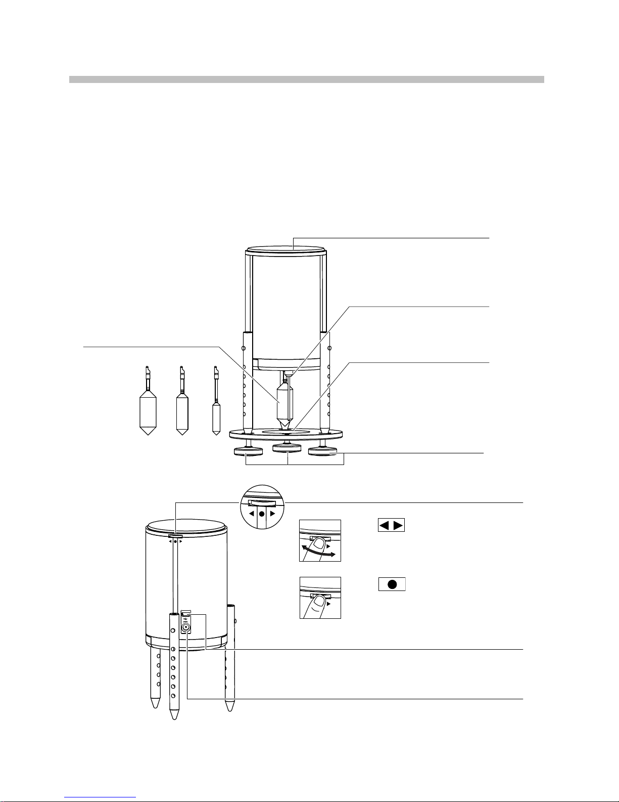
2-2 Names and Functions of Components
Stand
A base upon which the main unit is
placed.
The beaker attaches in the center.
Attach the small volume beaker
attachment when using the S Beaker.
Stand screws
Use to adjust the level.
Display
Displays measurement values
and settings.
Temperature sensor
Measures temperature
Anterior Illustration
A1 A2 A3
Spindle
Rotates to measure viscosity.
USB Mini-B port
Connects the instrument to a computer (Cp.19).
Remove the protective cap before use.
Slide (
)
Slide the dial button to change
settings and item selections.
Push (
)
Push the dial button to power the
instrument ON/OFF. Use to confirm
settings and item selections.
Posterior Illustration
Dial button
Operation
Power port
Connects the instrument to the AC adapter.
Remove the protective cap before use.
Page 13
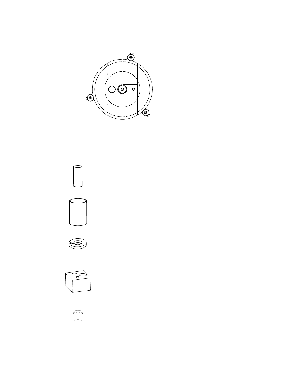
8
S Beaker (15mL)
Place sample in this container.
L Beaker (100mL)
Place sample in this container.
Small volume beaker attachment
Attach the small volume beaker attachment to the stand when
using the S Beaker.
Spindle stand
Insert the spindle and store upright.
Protective cap
Always attach the protective cap to the shaft holder when
storing the instrument in the carrying case.
N Remove the battery compartment cover to
attach/detach the protective cap.
Battery compartment screw
Turn to remove the battery
compartment cover.
Shaft holder
The spindle attaches here.
Remove the protective cap before use.
m Do not place excessive force or
undue stress on the shaft holder.
This may cause damage to the shaft
holder.
Temperature sensor attachment point
The temperature sensor attaches here.
Battery compartment
Remove the cover to insert and replace
batteries.
Underside Illustration (main unit)
Page 14
9
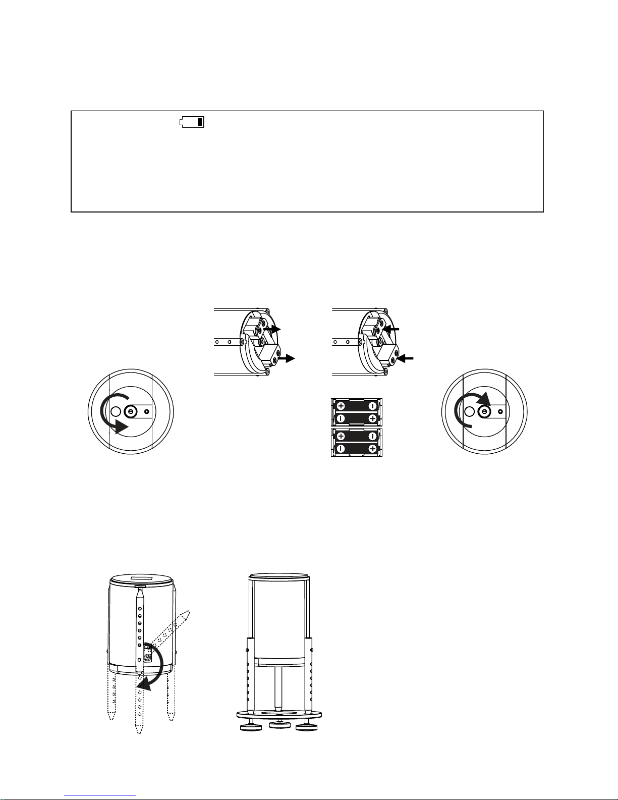
2-3 Inserting the Batteries (when using batteries as a power
source)
m
• When
is indicated, replace all batteries with brand new AA alkaline
batteries (x 4) .
• Check the expiration dates on batteries before purchase. Always use only
brand new batteries.
• Do not place the display-side of the instrument facedown. This may result in
damage to the display.
1.
Turn the battery
compartment screw
in the direction of
the arrow
(counterclockwise).
Remove the battery
compartment cover.
2.
Gently pull out the
battery case and insert
the batteries.
m Insert the
batteries,
observing the
correct polarities.
3.
Insert the
battery case.
4.
Affix the battery
compartment cover
and push it in, while
turning the battery
compartment screw
in the direction of
the arrow
(clockwise).
2-4 Setup
1.
Rotate the main unit's
legs and position it upright.
2.
Place the main
unit on the stand.
m Insert the legs into the grooves
on the stand.
m Subjecting the shaft holder to
sudden shock or excessive force
may result in damage and
malfunction. Always rotate the
instrument’s legs and keep the
instrument in an upright position,
except when storing it in its
protective case.
Page 15
10
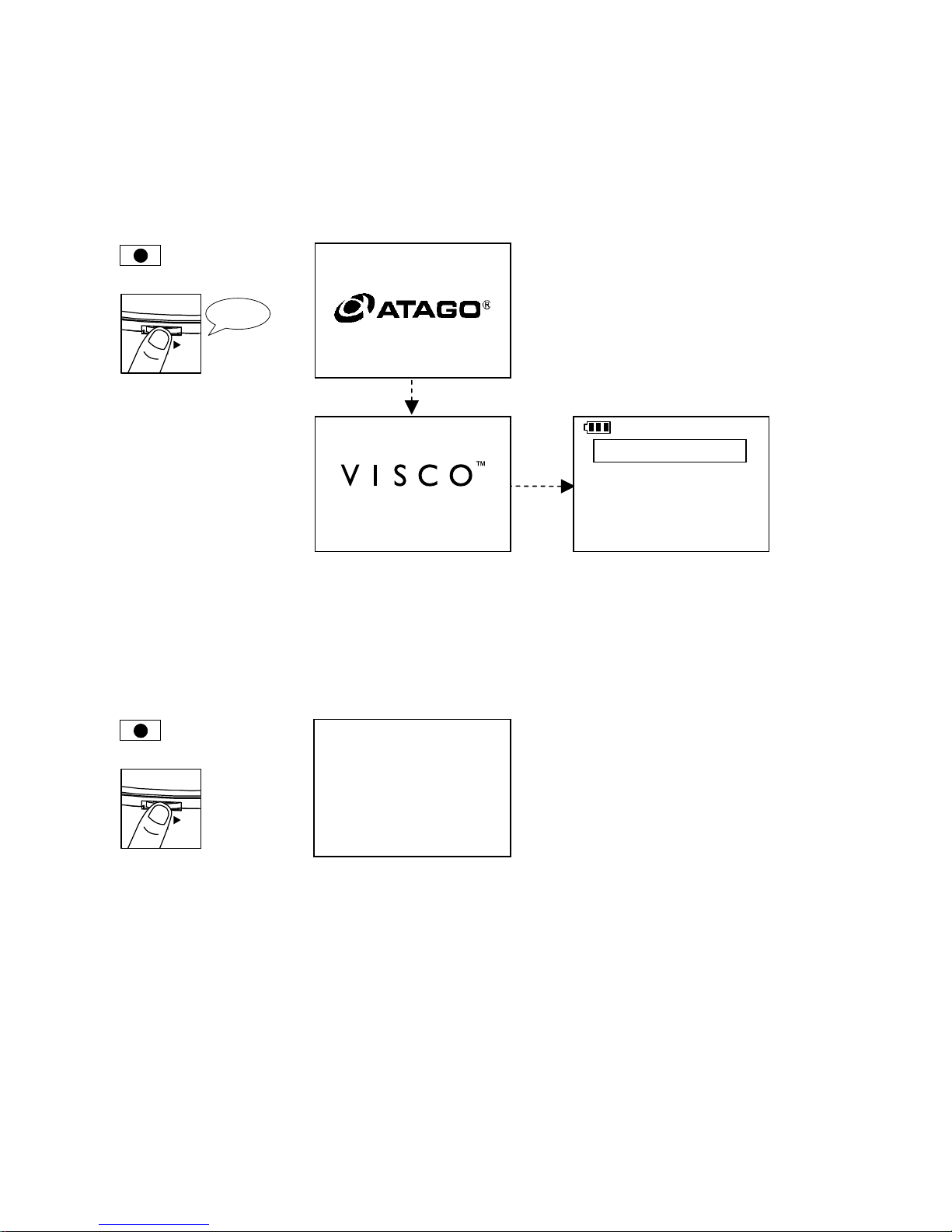
2-5 Power ON/OFF
Power ON
When using an external power source, connect the AC adapter to an indoor AC100 to 240V
(50Hz/60Hz) power outlet.
Push for 0.5
seconds.
(The soft ver. is for example.)
Power OFF
Push for at
least 3 seconds.
The display will turn off.
N When using batteries as a
power source, the instrument
will automatically power OFF
after 5 minutes of inactivity.
20.0°C
Measu r e m e nt
Level
Auto S t o p
User S c a l e
Setup
Ver.1.0 . 0
[Startup Screen]
Beep
[Main Menu Screen]
Page 16
11
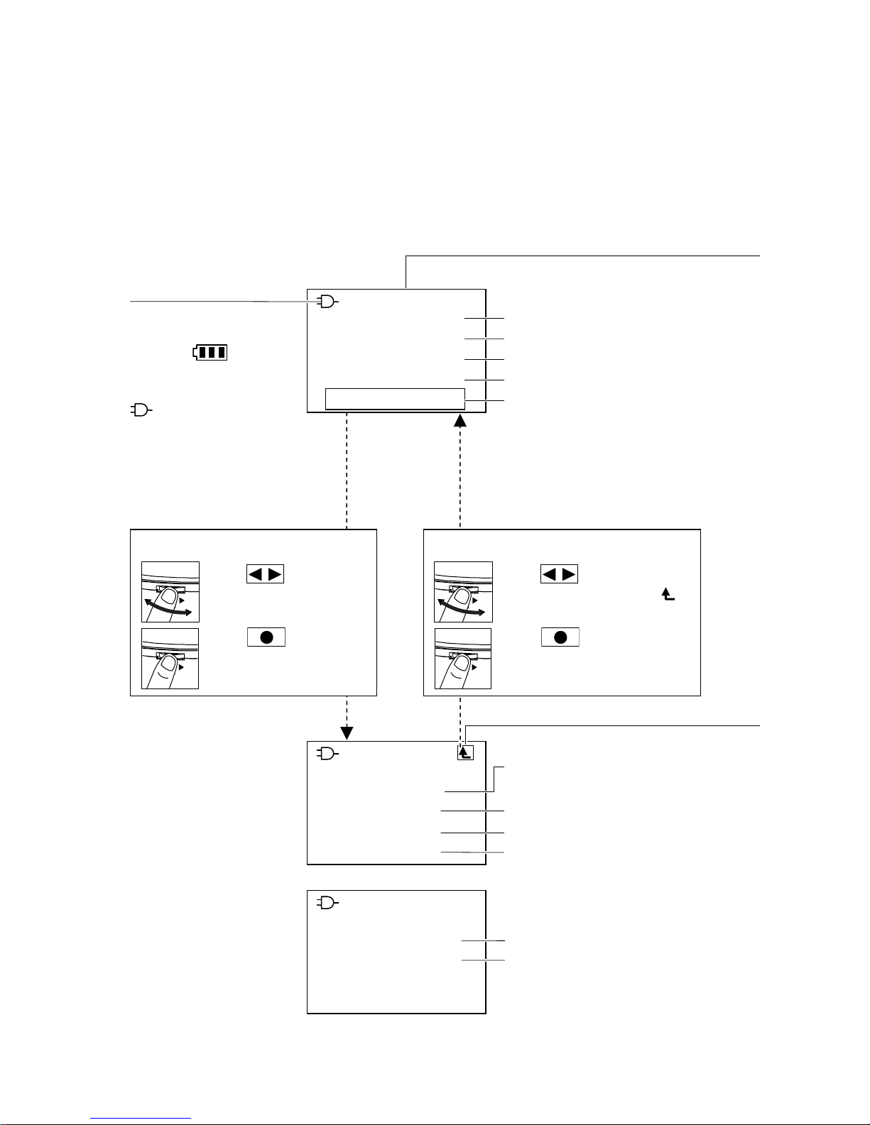
2-6 Displays
After the startup screen appears, the main menu screen will be displayed.
[Main Menu Screen]
From the main menu screen, you can switch the display between measurement, level check
and setup.
N After 30 seconds of inactivity, the brightness level will auto-adjust to "1."
[Setup Screen]
From the setup screen,
you can switch the
display between basic
settings,
moving average
and user calibration.
20.0°C
Measu r e m e nt
Level
Auto S t o p
User S c a l e
Setup
Temperature display
The temperature of the temperature
sensor will be displayed.
Remaining battery
charge/External power
supply indicator
Battery power source:
remaining battery charge
indicator
will be
displayed.
External power source:
will be displayed.
20.0°C
---Se t u p 2/2--- Movin g A v erage
Calib r a t i on
20.0°C
---Se t u p 1/2--- Langu a g e
Unit D i s p lay
Date/ T i m e
Brigh t n e s s
Return
The previous screen will be displayed.
Slide
to select
"Setup."
Push
to confirm
the selection. The setup
screen will be displayed.
Operation (e.g. setup)
Slide
to return to the
previous screen. Select (
).
Push
to confirm the
selection. The main menu
screen will be displayed.
Operation
Language (Cp.31)
[Japanese, English]
Unit Display (Cp.31)
Date/Time (Cp.32)
Brightness (Cp.32)
Moving Average(Cp.33)
User Calibration(Cp.34)
Measurement (Cp.13)
Level Check (Cp.12)
Auto Stop (Cp.25)
User Scale (Cp.27)
Basic Settings (Cp.31)
[Language, Unit Display,
Date/Time and Brightness]
Moving Average (Cp.33)
User Calibration (Cp. 34)
Page 17
12
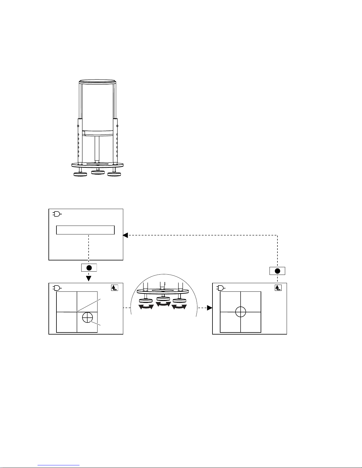
2-7 Level Check
Use the stand screws to adjust the level of the main unit.
Setup (Cp.9)
[Main Menu Screen]
20.0°C
Measu r e m e nt
Level
Auto S t o p
User S c a l e
Setup
20.0°C
Use the stand screws to
adjust the level. Align the
mark with the center of
the screen.
20.0°C
Center
Mark
Confirm
Page 18
13
3 Measurement
m
• Ensure that the main unit, spindle, temperature sensor, beaker and sample
are fully acclimated to the ambient temperature before taking measurements.
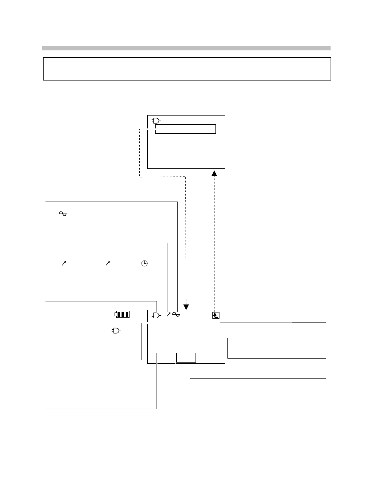
3-1 Measurement Screen
20.0°C
Measu r e m e nt
Level
Auto S t o p
User S c a l e
Setup
V 20.0° C
01 A1L 100.0 r p m
0.0
mPas
Max: 1,657 m P a s
Start
[Main Menu Screen]
Viscosity
The viscosity is displayed.
Speed
The speed is displayed.
The speed can be set.
Max viscosity value
The max viscosity value is displayed.
N This indicates the max viscosity
value that can be measured with
the selected spindle/beaker and
speed combination.
Temperature
The temperature of the
temperature sensor is displayed.
Start
Select "Start" to begin
measurement.
Return
The main menu screen will be
displayed.
[Measurement Screen]
Moving Average(Cp.33)
An icon will be displayed when this function is on.
ON:
OFF:Not displayed.
User Scale(Cp.27)
ON/OFF is displayed.
Set ON/OFF.
ON: 01 to10 (Scale Number)
OFF:--
Spindle/Beaker
The spindle and beaker combination is displayed.
Auto Stop(Cp.25)
An icon will be displayed when this function
is on.
ON:V (Viscosity), T (Torque), (Time)
OFF:Not displayed.
Remaining battery charge/External
power supply indicator
Battery power source: remaining
battery charge indicator
will be displayed.
External power source:
will be displayed.
Page 19
14
3-2 Measurement Procedures
Before taking measurements, refer to the "Maximum Measurement Values Guideline Chart"
and select the most suitable spindle and beaker for your application.
(C from p.42)
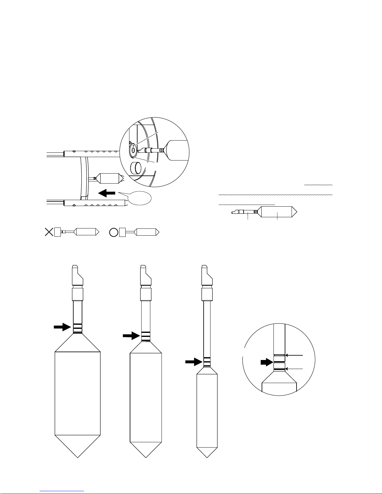
3-2-1 Spindle Preparation
Attach the spindle to the main unit.
m Insert the spindle all the way until you
hear a faint "click."
m Do not forcefully insert the spindle.
Do not insert the spindle at an
angle. Subjecting the shaft holder to
excessive force may cause damage.
m Do not grab or hold the spindle by
the tip with bare hands. Grasp the
shaft to insert the spindle. Wrap the
spindle in tissue paper if grabbing or
holding by the tip.
N Remove the protective cap.
Spindle Types
Mark
Shaft holder
click
A1 A2 A3
Fill lines
m The reference line
is between the fill
lines.
Reference
line
Reference line
Reference
line
Reference
line
Shaft
Tip
Page 20
15
3-2-2 Temperature Sensor Preparation
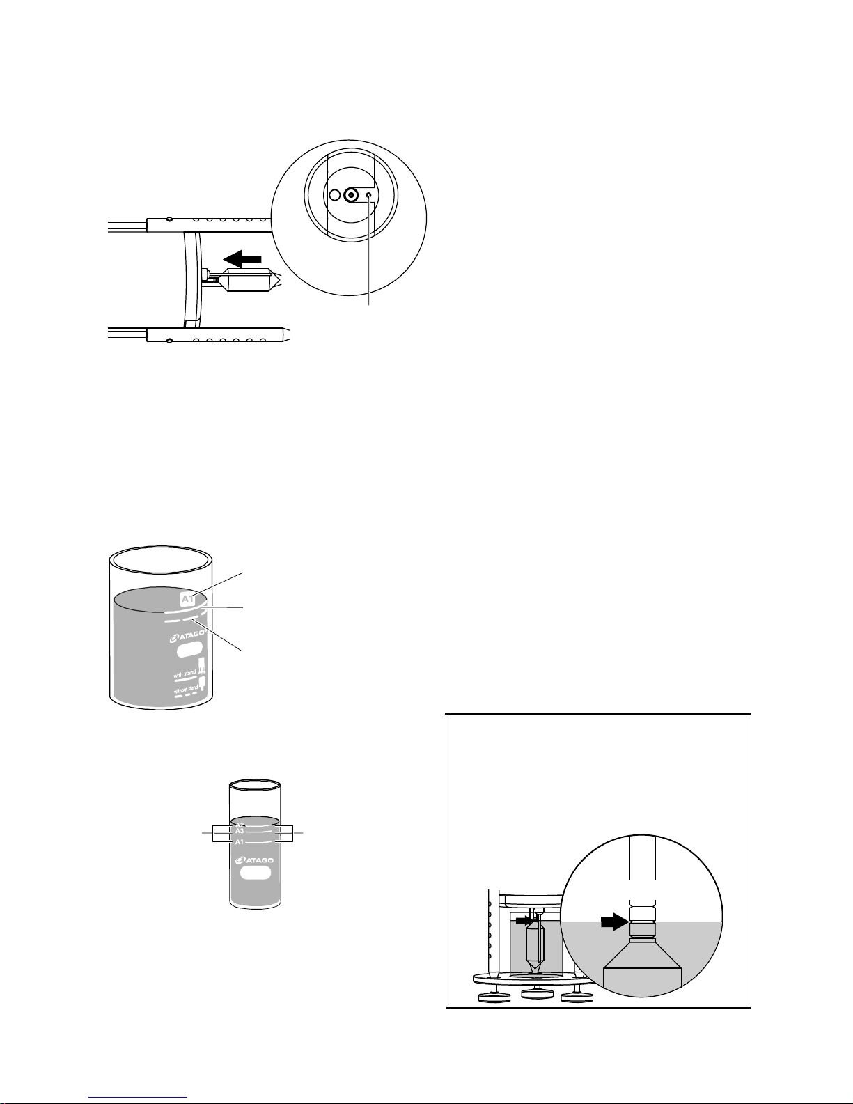
Attach the temperature sensor to the main unit (Cannot be used with S beaker).
m Insert the temperature sensor
all the way until you hear a faint
"click."
3-2-3 Sample Preparation
m The reference line most suited to
your application depends on the
type of spindle that is used.
m A reference line for normal
measurements and a reference
line for quick measurements are
present only on the L Beaker.
m Make sure that no air bubbles are
trapped in the sample.
1.
Pour some sample in the beaker up to the
reference line.*
L Beaker (100mL)
S Beaker (15mL)
N The illustration is for reference only and
may differ from the actual product.
* If reference lines are not present
on the beaker:
Align the surface of the sample with the
spindle's reference line.
Reference line
Spindle name
Reference line
Spindle name
Reference line (solid line)
For normal measurement use.
Reference line (dotted line)
For quick measurement use.
Temperature sensor
attachment point
Page 21
16
3-2-4 Beaker Setup
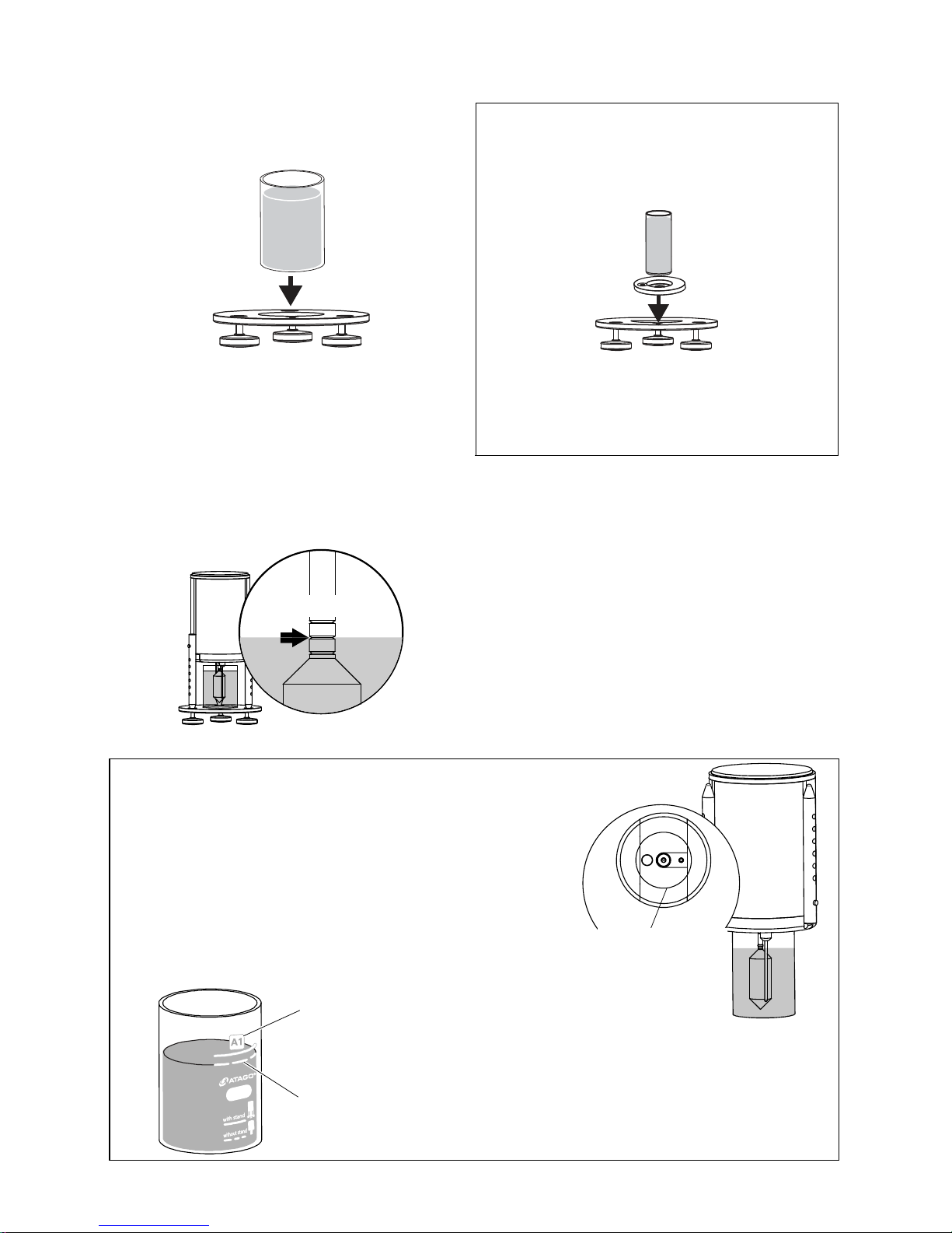
1.
Attach the beaker to the stand.
m Firmly attach the beaker, ensuring
there are no spaces or gaps between
the beaker and the stand.
If using the S Beaker:
Attach the small volume beaker adapter to
the stand. Then, attach the beaker.
m Firmly attach the small volume
beaker adapter and beaker, ensuring
there are no spaces or gaps
between them and the stand.
2.
Place the main unit on the stand.
Check that the surface of the sample is
level with the spindle's reference line.
m Be sure that the spindle and
temperature sensor do not come in
contact with the beaker.
m Make sure that no air bubbles are
trapped in the sample.
If air bubbles are present, let the
sample sit and settle in order to
remove the air bubbles.
Quick Measurements (accuracy not guaranteed)
Quick and easy measurements can be taken by placing
the main unit directly on the L Beaker.
m Quick measurements can only be taken with the
L Beaker.
m Pour some sample in the beaker up to the quick
measurement reference line.
Spindle name
Reference line (dotted line)
For quick measurement use.
Reference line
Align the beaker
with the groove.
Page 22
17
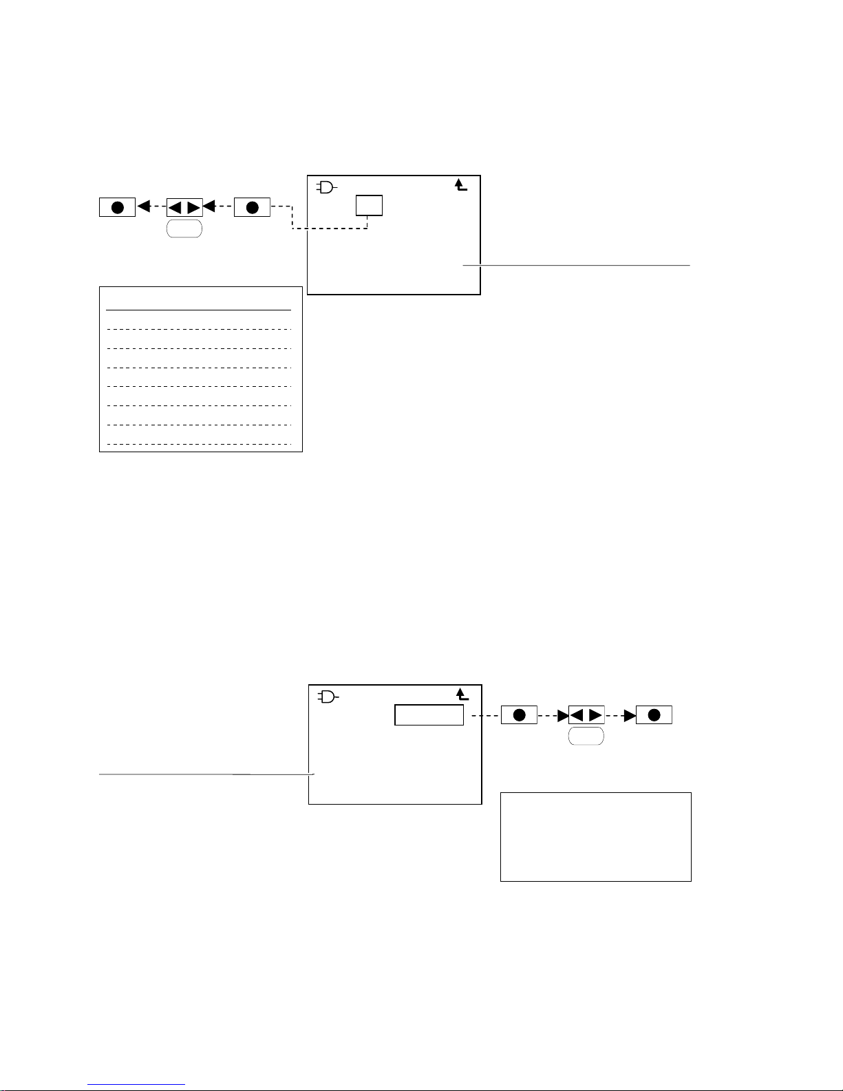
3-2-5 Spindle/Beaker Settings
This section explains how to set the spindle/beaker combination.
N Select UL when using Ultra Low
Adapter (ULA)-Sample Adapter
for Low Viscosity Sample (sold
separately).
3-2-6 Speed Settings
N Settings can be changed even during measurement.
N Select 2.5rpm or more
when using Ultra Low
Adapter (ULA)-Sample
Adapter for Low Viscosity
Sample (sold separately).
20.0°C
-- A1L 100.0rpm
0.0
mPas
Max: 1,657 m P a s
Start
0.5、0.6、1.0、1.5、2.0、2.5、
3.0、4.0、5.0、6.0、10、12、
20、30、50、60、100、150、
200、250 rpm
Blinking
Confirm
Select one of the speeds
listed below:
[Measurement Screen]
Max viscosity value
The max viscosity value will
change every time the speed is
switched.
20.0°C
-- A1L 100.0rpm
0.0
mPas
Max: 1,657 m P a s
Start
[Measurement Screen]
Item Spindle Beaker
A1S A1 S:15mL
A1L A1 L:100mL
A2S A2 S:15mL
A2L A2 L:100mL
A3S A3 S:15mL
A3L A3 L:100mL
UL - -------
Max viscosity value
The max viscosity value will
change every time the
combination is switched.
Confirm
Blinking
Select one of the items
listed below:
Page 23
18
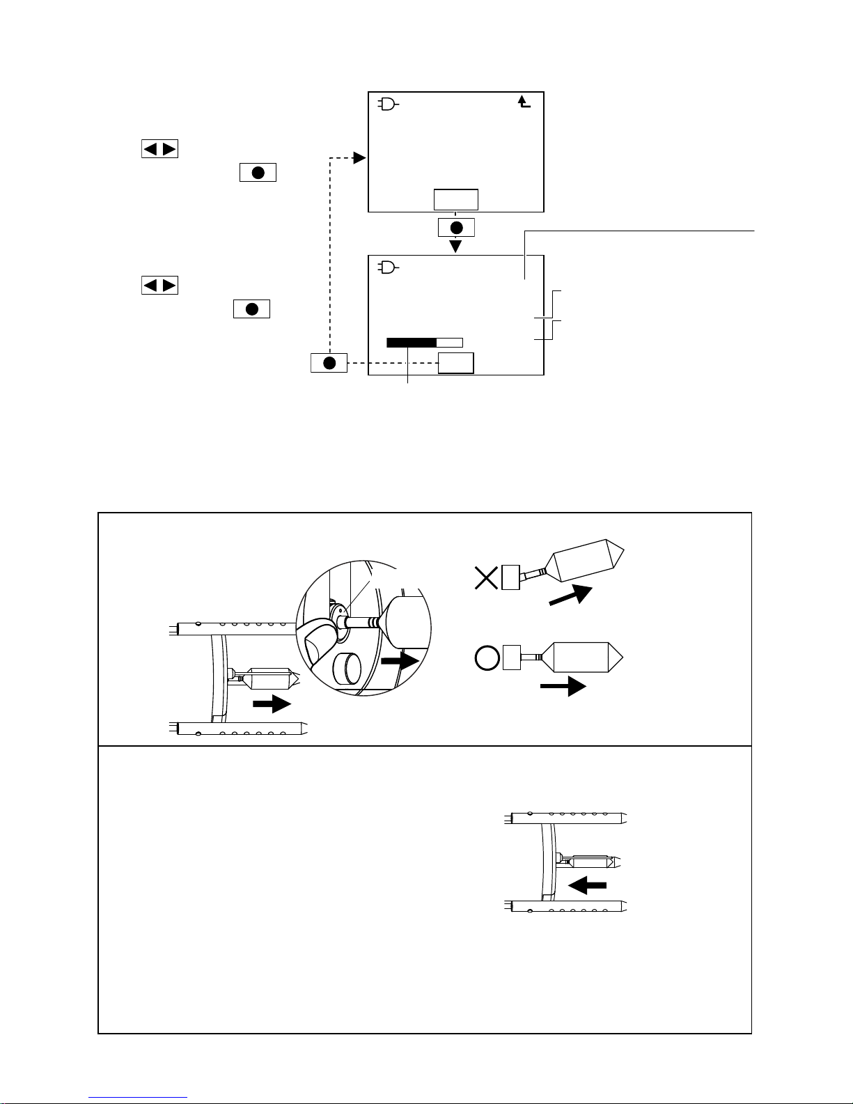
3-2-7 Measurement
Removing the spindle:
While pressing on the shaft
holder, pull the spindle
straight out.
If changing the spindle:
1.
Remove the spindle and temperature sensor.
2.
Attach the spindle you wish to use and the
temperature sensor. Be sure to wash the temperature
sensor before re-attaching (Cp.14).
m Make sure no sample residue is left on the
shaft holder or temperature sensor
attachment point.
m If sample residue is present on the spindle and temperature sensor, wash them
thoroughly.
m After changing the spindle, check that the surface of the sample is level with the
spindle's reference line.
20.0°C
-- A1L 100.0 r p m
0.0
mPas
Max: 1,657 m P a s
Start
Torque % bar
[Measurement Screen]
Slide
to select
"Start," then push
to confirm the selection
and begin measurement.
Slide
to select
"Quit," then push
to confirm the sel
ection
and terminate
measurement.
[Screen During Measurement]
20.0°C
-- A1L 200.0 r p m
558.2
mPas
67.4%
Quit
Viscosity
Speed
N
Settings can be changed
even during measurement.
Torque %
N The recommended
range is 10.0 to 100.0% (and 5.0
to 100.0% when using Ultra Low
Adapter (ULA)-Sample
Adapter for Low Viscosity
Sample (sold separately)).
If the value falls outside of the
above range, a "beep" will be
emitted.(Cp.39)
Shaft holder
Page 24
19
3-3 Computer Output
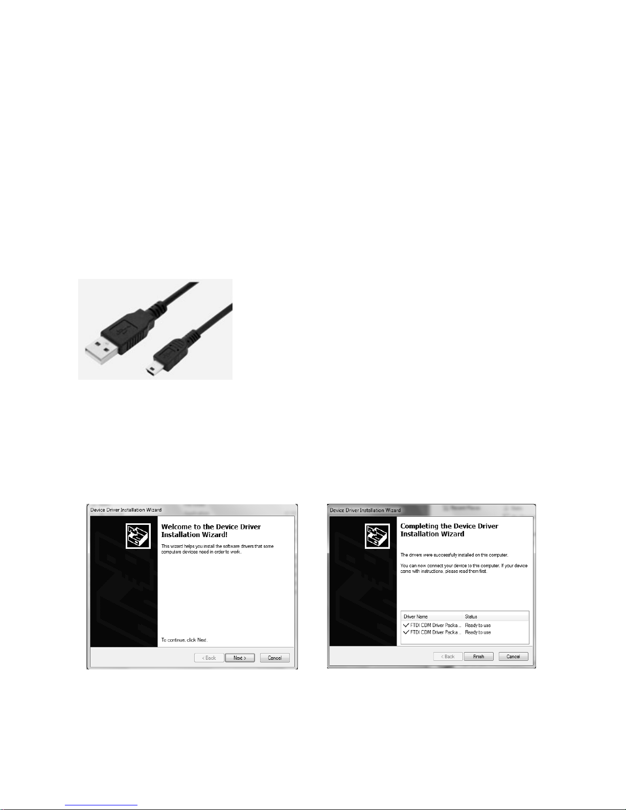
The instrument outputs measurement results in real-time via USB Mini-B.
3-3-1 Driver Installation
To have the instrument recognized by the PC, download a FTDI driver on the PC from the
link below:
※ Install the virtual COM port (VCP) driver.
http://www.ftdichip.com/FTDrivers.htm
1.
Ensure that the PC has started up completely.
2.
Connect the cable to the instrument (see the posterior illustration on page 7, "Names
and Functions of Components") and the PC.
3.
Turn the instrument on.
Installation instructions are as follows (Windows 7 is used as an example):
4.
"Device Driver Installation Wizard" will
pop up.
5.
Once the driver installation is complete,
the instrument is recognized by the PC.
USB type A (left) and USB type Mini-B (right)
Page 25
20
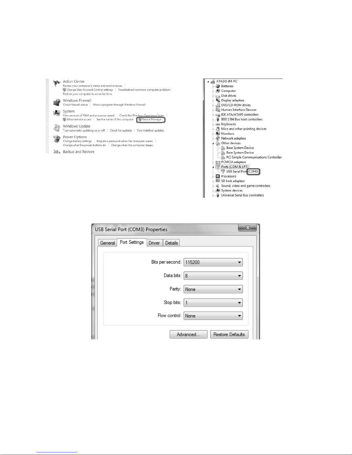
6.
From "Control Panel," open "System
and Security."
Click on "Device Manager," under
"System."
7.
From the "Device Manager" options,
click "Ports." Ensure that USB Serial Port
(COM#) appears. Check the port number. In
the example shown below, the port is
COM3.
8.
Click "USB Serial Port(COM"*")." From the "USB Serial Port(COM"*") Properties"
window, configure the computer's COM port settings as shown below.
m The port number may vary, depending on the PC and other connecting devices.
※ Windows 98, Windows 2000, Windows Me, Windows XP, Windows Vista, and Windows 7,
Windows 8 and Windows 10 are registered trade marks of Microsoft Corporation in the
United States and other countries.
Page 26
21
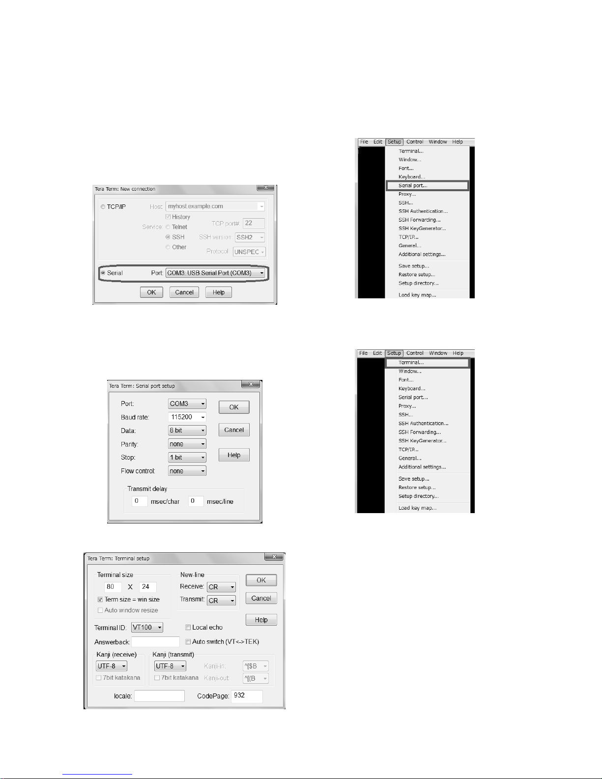
3-3-2 Computer - Data Setting
Download Tera Term from a website, such as the one below:
http://ttssh2.sourceforge.jp/index.html.en
1.
Start Tera Term.
Select "Serial," and select the port number,
which was confirmed in step 7 of "Driver
Installation," on page 20, from the "Port:"
drop-down menu.
2.
Click "Setup," and then "Serial port."
3.
In the "Serial port setup" dialog box,
enter the settings as shown below for the
port number selected in step 7 of "Driver
Installation," on page20.
4.
Click "Setup," and then "Terminal."
5.
Enter the settings as shown below .
Page 27
22
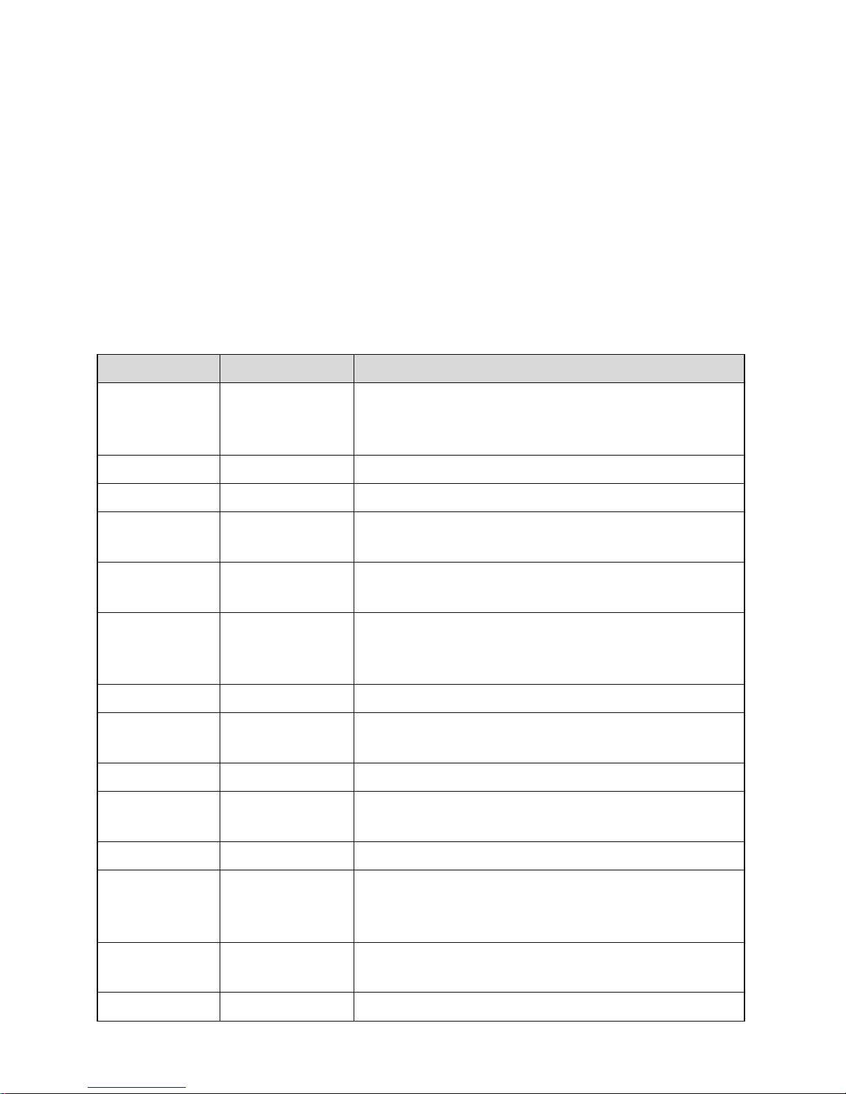
3-3-3 Data Output From Instrument to PC
Begin measurement.
Every time a measurement is taken (every time the spindle rotates), a new row of data
appears in the Tera Term window.
• Data is output in ASCII code.
• Each item is separated by a comma.
[Data Display]
04/13/16,15:41:24,251.8,251.8,341.8,341.8,2037,mPas,12.4,12.4,27.9,degC,A2S,60.0,
Constant,1,01,10.0,20.0,30.0,100.0,110.0,120.0,-1.276756e-15,1.000000e+00,9.000000e+01
Data Display
Item Item Detail
04/13/16 Date MM/DD/YY
(Under Japanese language settings, the date will be
displayed in the format "YY/MM/DD")
15:41:24 Time HH:MM:SS
251.8 Viscosity
251.8 Moving Average
Viscosity
341.8 User Scale
Viscosity
341.8 User Scale
Average
Viscosity
2037 Max Viscosity
mPas Unit readout
(viscosity)
mPa・s / cP
12.4 Torque %
12.4 Moving Average
Torque %
27.9 Temperature
deg C Unit readout
(temperature)
deg C / deg F
(Under Japanese language settings, the temperature
unit readout can be displayed in either "℃" or "°F")
A2S Spindle/beaker
combination
60.0 Speed rpm
Page 28
23
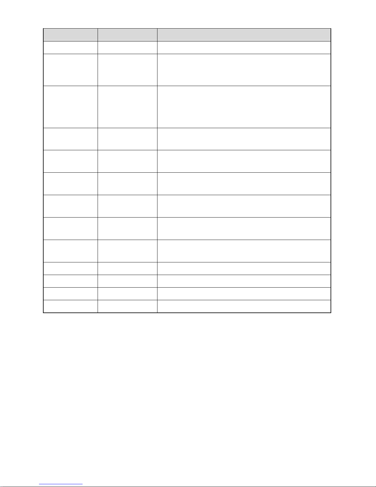
Data Display
Item Item Detail
Constant Motor status Constant, Acceleration or Deceleration
1 Moving Average
Function
ON/OFF
O : Moving average function is off.
1: Moving average function is on.
01 User Scale
Function
ON/OFF and
Scale Number
--:User scale function OFF
01 to10: Scale Number (User scale function ON)
10.0 X1 User Scale Input Value (Measurement Value 1 on this
device)
20.0 X2 User Scale Input Value (Measurement Value 2 on this
device)
30.0 X3 User Scale Input Value (Measurement Value 3 on this
device)
100.0 Y1 User Scale Input Value (Measurement Value 1 on
another viscometer)
110.0 Y2 User Scale Input Value (Measurement Value 2 on
another viscometer)
120.0 Y3 User Scale Input Value (Measurement Value 3 on
another viscometer)
-1.276756e-15 a "a" in user scale conversion equation v=ax2+bx+c
1.000000e+00 b "b" in user scale conversion equation v=ax2+bx+c
9.000000e+01 c "c" in user scale conversion equation v=ax2+bx+c
Line terminator CR LF
3-3-4 Saving Data and Disconnecting
Follow the instructions on saving files in Windows and Tera Term to save data.
Close Tera Term to end communication.
Page 29
24
4 Cleaning
4-1 Main Unit
m
• Disconnect all the cables and power OFF the instrument.
• Place the protective cap on the shaft holder after use.
• Subjecting the shaft holder to sudden shock or excessive force may result in
damage and malfunction. Always rotate the instrument’s legs and keep the
instrument in an upright position, except when storing it in its protective
case.
Gently wipe off the instrument using the cleaning methods outlined below:
• A soft, dry cloth, such as a lens or microfiber cloth.
• A cloth moistened with mild soap or ethyl alcohol.
4-2 Spindles
m
• Wash the spindles after every use.
• When using highly volatile or flammable solvents, be sure to wear appropriate
protective clothing, such as gloves, masks, etc.
• Wash the instrument with lukewarm water.
• Use mild soap, ethyl alcohol, or acetone when necessary.
5 Error Messages
HHH : [Viscosity] This error message will appear If the torque value exceeds 100%.
(Refer to the "Abnormal Measurement Values" Cp.39)
[Temperature] This error message will appear if the temperature exceeds
105.0˚C (221.0˚F).
LLL : [Temperature] This error message will appear if the temperature is below -5.0˚C
(27.0˚F).
It will also appear if the temperature sensor is not attached.
Page 30
25
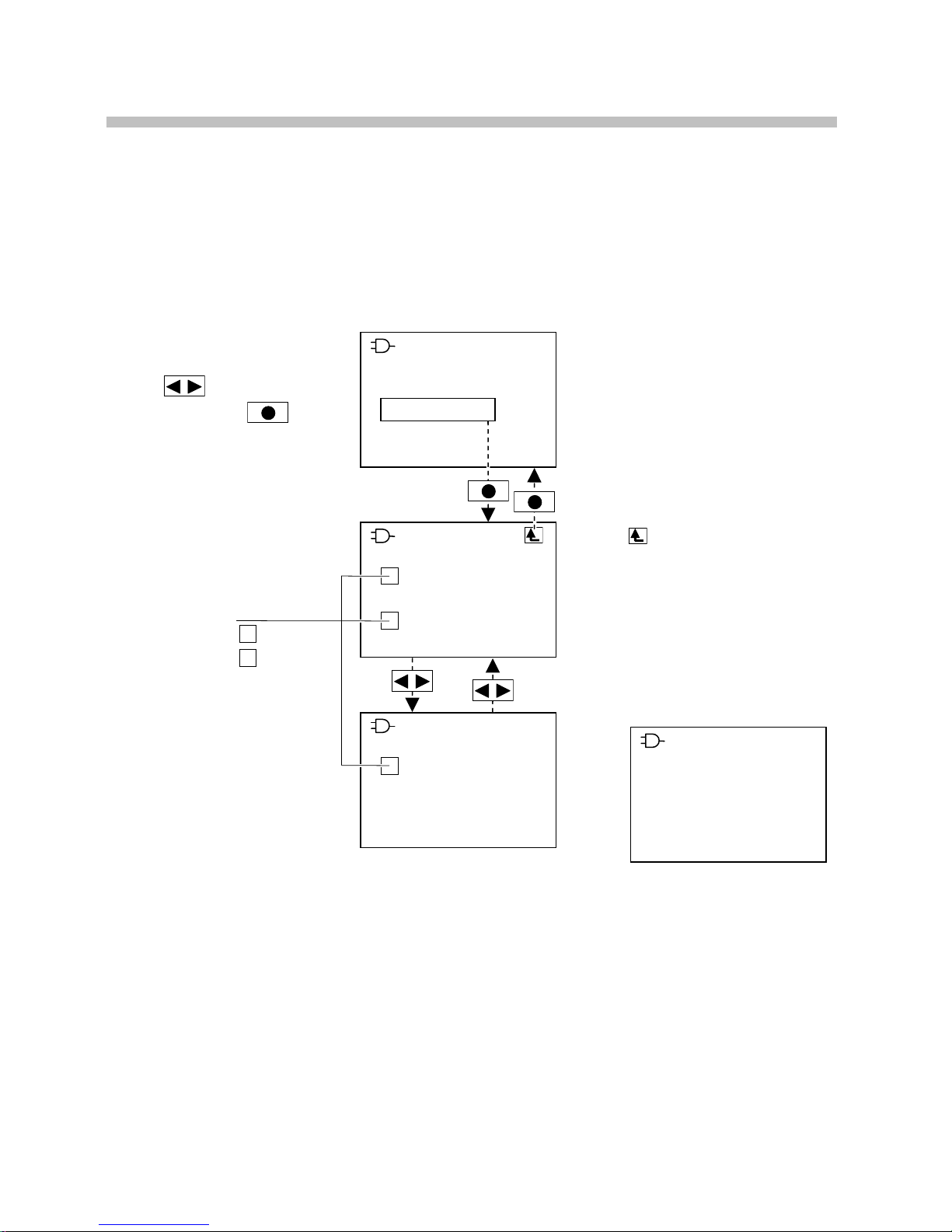
6 Auto Stop
This function will automatically stop taking measurements when a set value is reached.
This effectively measures the viscosity and torque % of a sample that changes over time by
displaying a measurement value once it has stabilized. The set value can be selected from
viscosity, torque, or time.
6-1 Screen Display
20.0°C
Measu r e m e nt
Level
Auto S t o p
User S c a l e
Setup
[Main Menu Screen]
20.0°C
--Aut o S t op1/2-Visco s i t y :
0.0mP a s
Torqu e : 0.0%
20.0°C
--Aut o S t op2/2-Time: 0 0 h 0 0m00s
Enter Q u i t
[Confirm Save Screen]
N
Returns to the main
menu screen, but will
display the save
confirmation screen if
pressed after an input
value has been
changed.
20.0°C
---Au t o S top--Setti n g s were
not s a v e d .
Exit s e t u p?
Enter Q u i t
✓
ON/OFF
: ON
: OFF
Slide
to select an
item, then push
to
confirm the selection.
Page 31
26
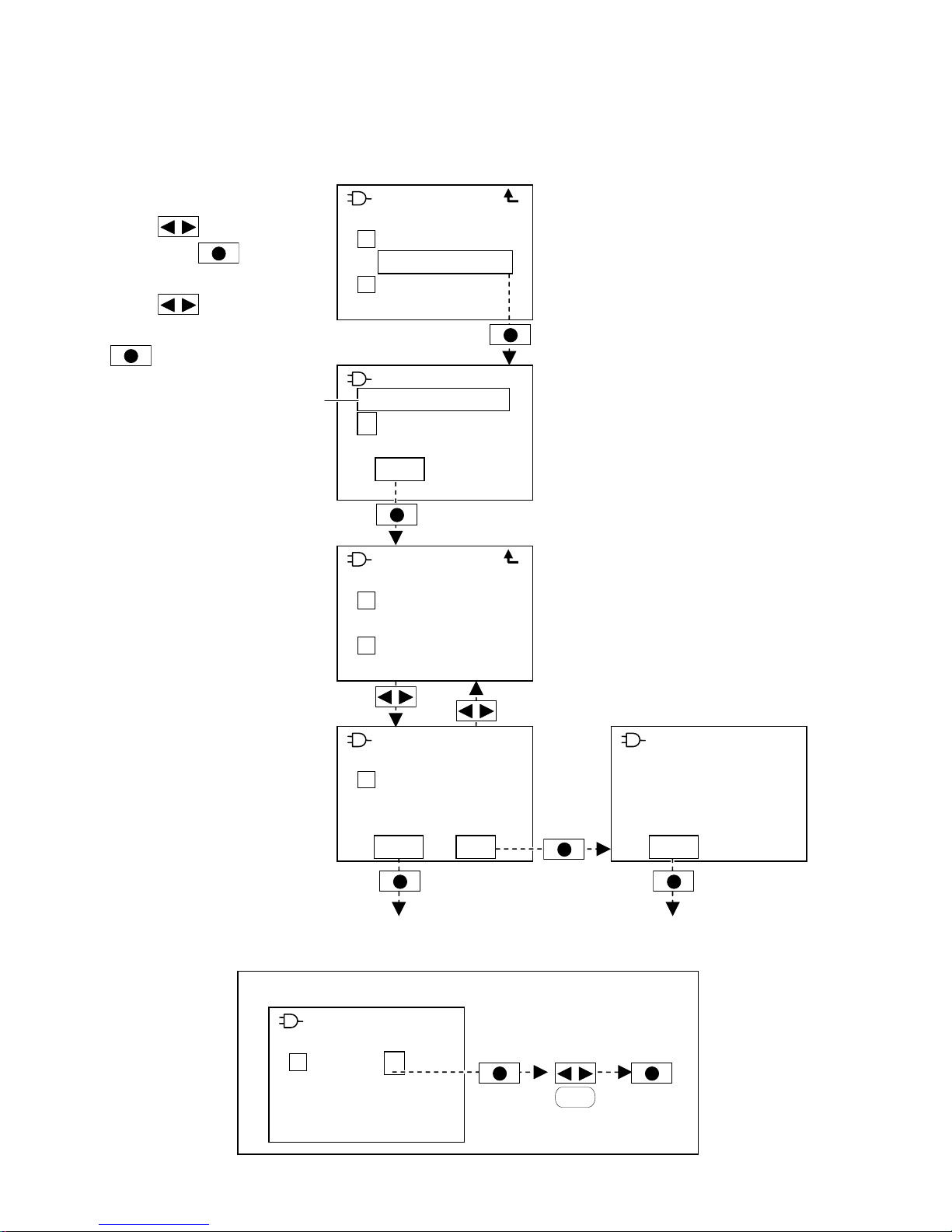
6-2 Auto Stop ON/OFF and Setting Value Input
This section explains the auto stop function using viscosity as an example.
20.0°C
1767. 0
1 2 3 4 5 6 7 8
9 0 . ← →
Back
Enter Q u i t
[Auto Stop Screen]
←→: use the arrows
to move the
cursor.
Back:
select "Back" to
delete the value
to the left of the
cursor.
Input field
Slide
to select
viscosity value, then push
to continue to the
input screen.
N Select "Quit" to discard
settings and return to the
auto stop screen.
N
Values up to 1 decimal place
can be input.
Slide
to select Visc,
then push
to check
the box.
20.0°C
--Aut o S t op1/2-Visco s i t y :
0.0mPas
Torqu e : 0.0%
✓
20.0°C
--Aut o S t op2/2-Time: 0 0 h 0 0 m00s
Enter Q u i t
✓
Blinking
00 to 59
Inputting a time duration
example:minutes
20.0°C
--Aut o S t op2/2-Time: 0 0 h 0 0m00s
Enter Quit
20.0°C
--Aut o S t op1/2-Visco s i t y :
1767.0mPas
Torqu e : 0.0%
✓
N To turn off the auto stop
function, uncheck the
selection item boxes.
20.0°C
---Au t o S top--Setti n g s were
not s a v e d .
Exit s e t u p?
Enter Q u i t
Save
Exit without
saving
[Main Menu Screen]
[Main Menu Screen]
Page 32

27
7 User Scale
This function allows the VISCO to display the same measurement values as a B-Type
viscometer or other viscometer type.
A user scale is created for each sample.
The relationship between the measurement value from other viscometers (y) and the VISCO
(x) is y = ax2+bx+c
By inputting the viscosity measured by this device and another viscometer at three different
speeds, the VISCO will automatically calculate the conversion factors a, b, and c.
• A maximum of 10 user scales can be saved.
• Turning the User Scale Function ON/OFF or selecting a Scale Number can be done
from the measurement screen.
7-1 Preparation
Choose three speeds that will each be used by the VISCO and the other viscometer.
Prepare the measurement sample.
Measure the sample at all three speeds with the VISCO and the other viscometer.
The measurement value to enter into the VISCO is the value at which it stabilizes.
m Ensure that the sample temperatures are the same.
[Example]
Scale Number:01
Sample:A
Viscosity[mPa・s]
Speed
Number
Speed
[rpm]
The VISCO's
Measurement
Value(X)
Other Viscometer's
Measurement
Value(Y)
1 30 5449 5810
2 50 4451 4763
3 60 4157 4400
Page 33
28
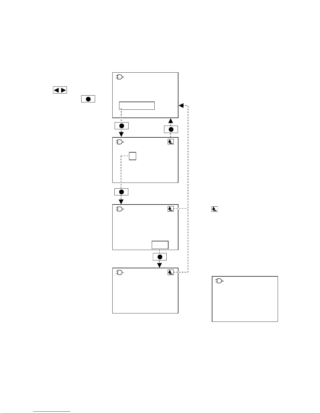
7-2 Creating a User Scale
This section will explain how to create an example Scale Number 01.
7-2-1 Screen Display
20.0°C
Scale S e t ting 01
X1: 5449. 0 m P a s
X2: 4451. 0 m P a s
X3: 4157. 0 m P a s
Next>
[Scale Setting (X) Screen]
20.0°C
Scale S e t ting 01
Y1: 5810. 0 m P a s
Y2: 4763. 0 m P a s
Y3: 4400. 0 m P a s
<Back E n t e r
[Scale Setting(Y)Screen]
20.0°C
Measu r e m e nt
Level
Auto S t o p
User S c a l e
Setup
[Main Menu Screen]
Slide
to select an
item, then push
to
confirm the selection.
20.0°C
Scale S e l ection
01 05 09
02 06 10
03 07
04 08
[Scale Setting Screen]
N
returns to the main
menu screen, but will
display the save
confirmation screen if
pressed after an input
value has been
changed.
[Save Confirmation Screen]
20.0°C
Scale S e t ting 01
Setti n g s were
not s a v e d .
Exit s e t u p?
Enter Q u i t
Page 34
29
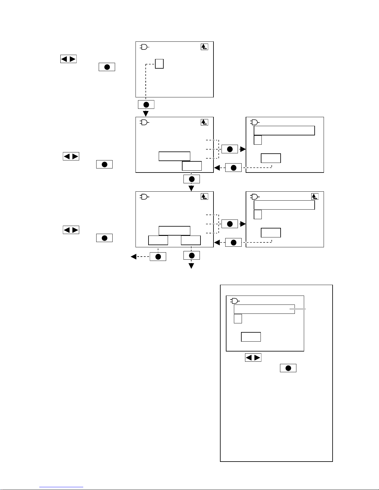
7-2-2 Viscosity Input
[Scale Selection Screen]
Slide
to select a scale
number, then push
to
confirm the selection.
20.0°C
Scale S e l ection
01 05 09
02 06 10
03 07
04 08
20.0°C
Scale S e t ting 01
X1: 5449. 0 m P a s
X2: 4451. 0 m P a s
X3: 4157.0 mPas
Next>
[Scale Setting (X) Screen]
Input the three
measurement values from
the VISCO.
Slide
to select an
item, then push
to
continue to the input screen.
20.0°C
4157. 0
1 2 3 4 5 6 7 8
9 0 . ← →
Back
Enter Q u i t
20.0°C
Scale S e t ting 01
Y1: 5810. 0 m P a s
Y2: 4763. 0 m P a s
Y3: 4400.0 mPas
<Back Enter
[Scale Setting (Y) Screen]
Input the three
measurement values from
the other viscometer.
Slide
to select an
item, then push
to
continue to the input screen.
[Main Menu Screen]
Save
[Scale Setting (X) Screen]
20.0°C
4400. 0
1 2 3 4 5 6 7 8
9 0 . ← →
Back
Enter Q u i t
[Input Screen]
[Input Screen]
m
Turning the user scale function ON/OFF
and selecting a scale number is done from
the measurement screen (Cp.30).
m
If attempting to input the same viscosity for
X1, X2, X3, a beeping sound will indicate that
this setting is invalid.
If attempting to input the same viscosity for
Y1, Y2, Y3, a beeping sound will indicate that
this setting is invalid.
N Select "Quit" to cancel
settings and return to the
Scale Setting screen.
N Values up to 1 decimal
place can be input.
←→: use the arrows to
move the cursor.
Back: select "Back" to
delete the value to the
left of the cursor.
Slide
to select a number
value, then push
to input it.
20.0°C
4157. 0
1 2 3 4 5 6 7 8
9 0 . ← →
Back
Enter Q u i t
Input
Field
About the input screen
Page 35
30
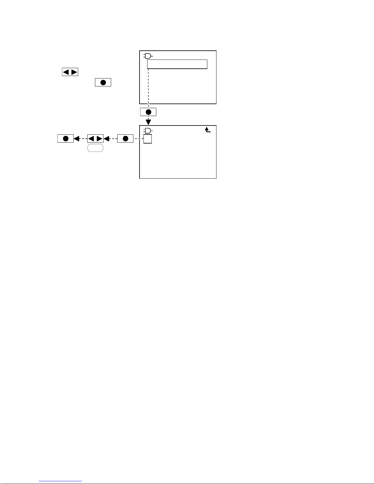
7-2-3 User Scale ON/OFF and Scale Number Settings
20.0°C
Measu r e m e nt
Level
Auto S t o p
User S c a l e
Setup
[Main Menu Screen]
20.0°C
-- A1L 1 0 0 . 0 r pm
0.0
mPas
Max: 1,657 m P a s
Start
Slide
to select an
item, then push
to
confirm the selection.
[Measurement Screen]
Blinking
ON :01 to 10
(Scale Number)
OFF :--
Page 36
31
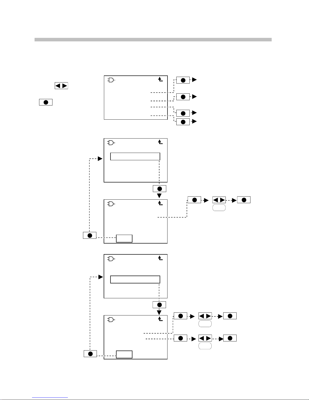
8 Basic Settings (setup)
This section explains how to configure language, unit display, date/time and brightness
settings.
8-1 Setup Screen
8-1-1 Language
8-1-2 Unit Display
20.0°C
--Uni t D i splay-Visc. : m P as
Temp. : °C
Enter Q u i t
20.0°C
---Se t u p 1/2--- Langu a g e
Unit D i s p lay
Date/ T i m e
Brigh t n e s s
Viscosity
[mPa・s, cP]
Temperature
[˚C, ˚F]
Blinking
℃, °F
Blinking
mPas, cP
Confirm
N Select "Quit" to cancel
settings and return to the
setup screen.
Japanese
English
Confirm
20.0°C
----L a n g u age---Lang. : E n glish
Enter Q u i t
Blinking
ニホンゴ, English
N Select "Quit" to cancel
settings and return to the
setup screen.
20.0°C
---Se t u p 1/2----
Langu a g e
Unit D i s p lay
Date/ T i m e
Brigh t n e s s
20.0°C
---Se t u p 1/2--- Langu a g e
Unit D i s p lay
Date/ T i m e
Brigh t n e s s
Slide
to select
an item, then push
to confirm.
Language (Cp.31)
[Japanese, English]
Unit Display (Cp.31)
[Viscosity, Temperature]
Date/Time (Cp.32)
Brightness (Cp.32)
Page 37
32
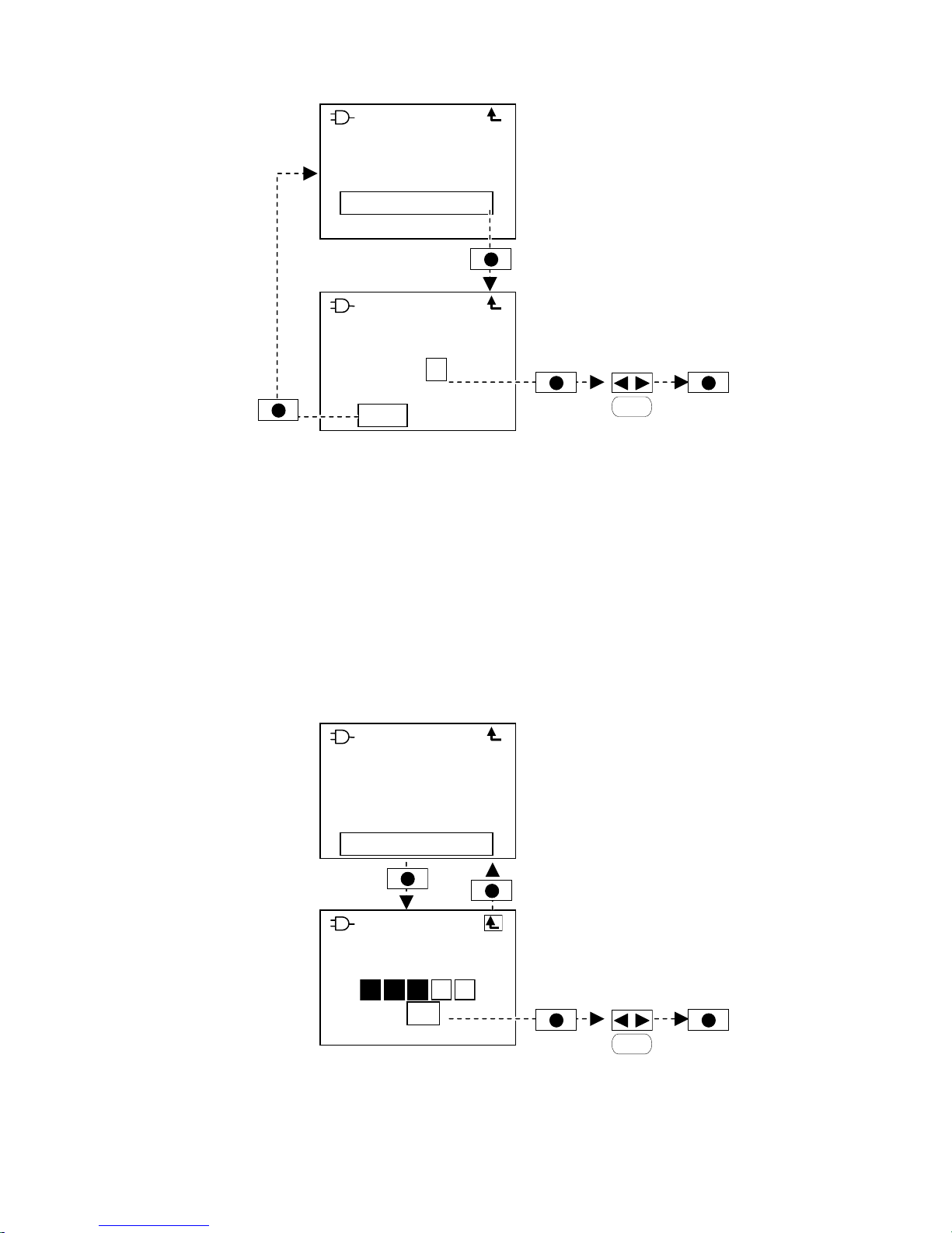
8-1-3 Date/Time
8-1-4 Brightness
20.0°C
---Br i g h t ness---
-
+
3
20.0°C
---Se t u p 1/2--- Langu a g e
Unit D i s p lay
Date/ T i m e
Brigh t n e s s
5 levels
Blinking
1 to 5
N Level 1 is the dimmest
setting, level 5 is the
brightest.
Confirm
20.0°C
---Da t e / T ime---Date: 0 9 / 07/15
Time: 1 0 : 46 :37
Enter Q u i t
20.0°C
---Se t u p 1/2--- Langu a g e
Unit D i s p lay
Date/ T i m e
Brigh t n e s s
MM/DD/YY
HH:MM:SS
example: minutes
Blinking
00 to 59
N Select "Quit" to cancel
settings and return to the
setup screen.
N "Beeping" tones will be
emitted when an error
occurs. Content containing
errors will be indicated by
flashing.
Confirm
Page 38
33
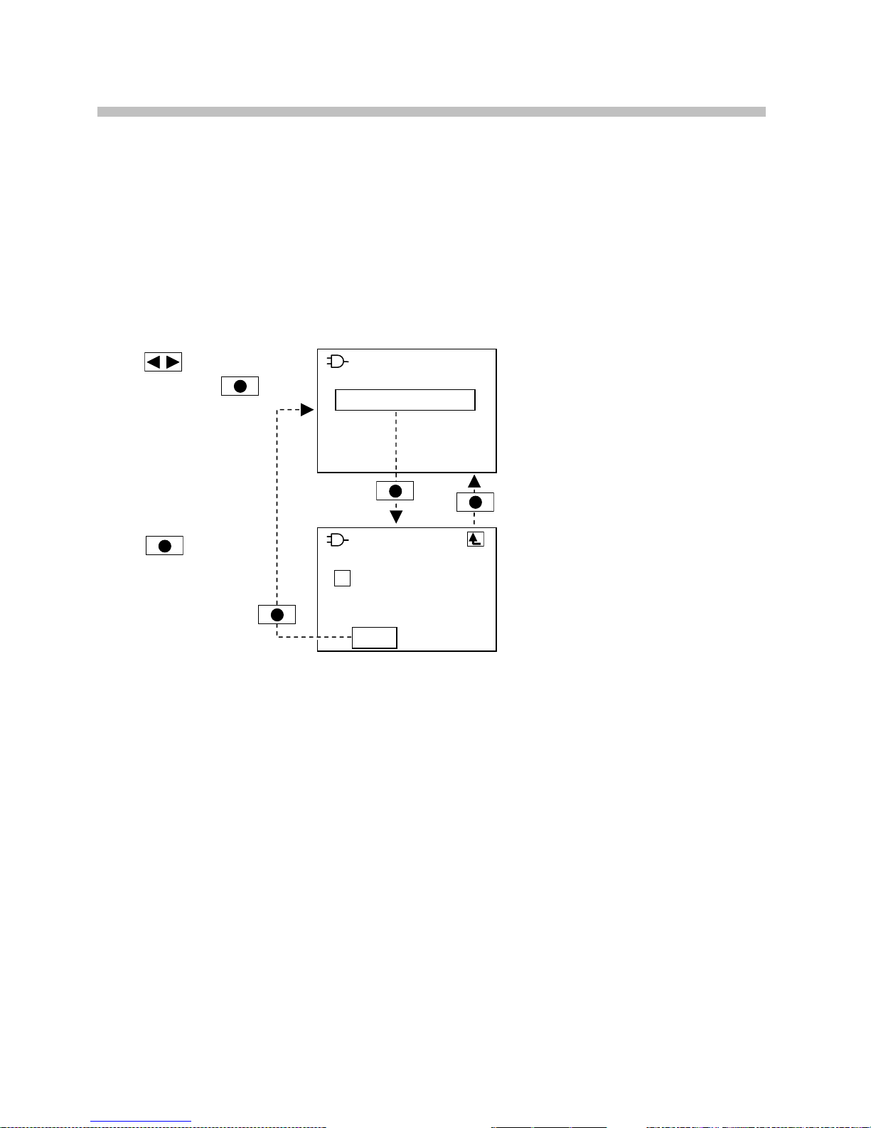
9 Moving Average
Effective for reducing inconsistent display values when measuring samples that do not show
a stable measurement value.
Displays the average (viscosity and torque %) of the 5 most recent readings.
For the first 4 readings, displays the average of the measurement values taken so far.
9-1 Moving Average ON/OFF
[Setup Screen (Setup 2/2)]
20.0°C
---Se t u p 2/2--- Movin g A v erage
Calib r a t i on
20.0°C
-Movi n g A verage-
Movin g A v erage
Enter Q u i t
Push
to check
the box.
Slide
to select an
item, then push
to confirm the selection.
✓
Confirm
N To turn off the moving
average function,
uncheck the selection
item box.
N Select "Quit" to
discard settings and
return to the setup 2/2
screen.
Page 39

34
10 User Calibration
The instrument can be calibrated with standard liquid (1 point calibration). Select one
standard liquid from among the following: JS200, JS500, JS1000, or JS2000 (refer to
"Optional Accessories and Replacement Parts," Cp.41).
If abnormal measurement values occur, perform the following checks as illustrated below.
10-1 Troubleshooting Tips
See "Abnormal Measurement Values" on p.39.
Measure standard liquid (Cp.13)
N Check the viscosity of the standard liquid by using the temperature conversion
chart included with the standard liquid as reference.
Viscosity will differ, depending on the temperature.
Within accuracy range→Normal
Outside accuracy range
↓
Perform user calibration (Cp.35)
↓
Measure standard liquid (Cp.13)
Within accuracy range→Normal
Outside accuracy range
↓
Restore default calibration settings (Cp.38)
↓
Measure standard liquid (Cp.13)
Within accuracy range→Normal
Outside accuracy range
↓
Contact ATAGO for service and repair (Cp.44)
Page 40
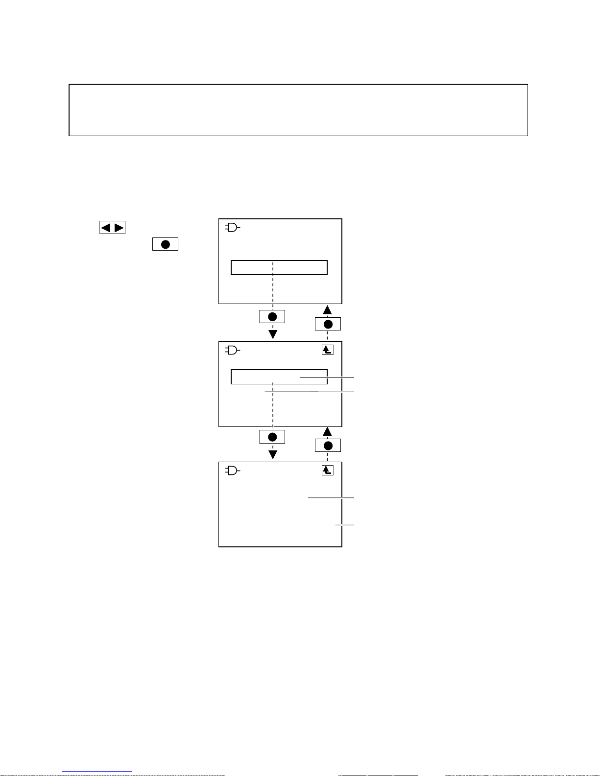
35
10-2 User Calibration
m
• Ensure that the main unit, spindle, temperature sensor, beaker and standard
liquid are fully acclimated to the ambient temperature before performing
calibration.
10-2-1 Display
[Setup Screen (setup 2/2)]
20.0°C
---Se t u p 2/2---Movin g A v erage
Calib r a t i on
20.0°C
--Cal i b r a tion-- User C a l i br.
Reset
20.0°C
--Use r C a libr.--
Spind l e : A1L
Visco s i t y :
1767. 0 0 m P as
Start
[Calibration Menu Screen]
[Calibration Screen]
Spindle/beaker setting
Standard liquid viscosity
setting
Slide
to select an
item, then push
to confirm the selection.
User calibration
Restore Default Calibration
Settings (Cp.38)
(example display)
Page 41
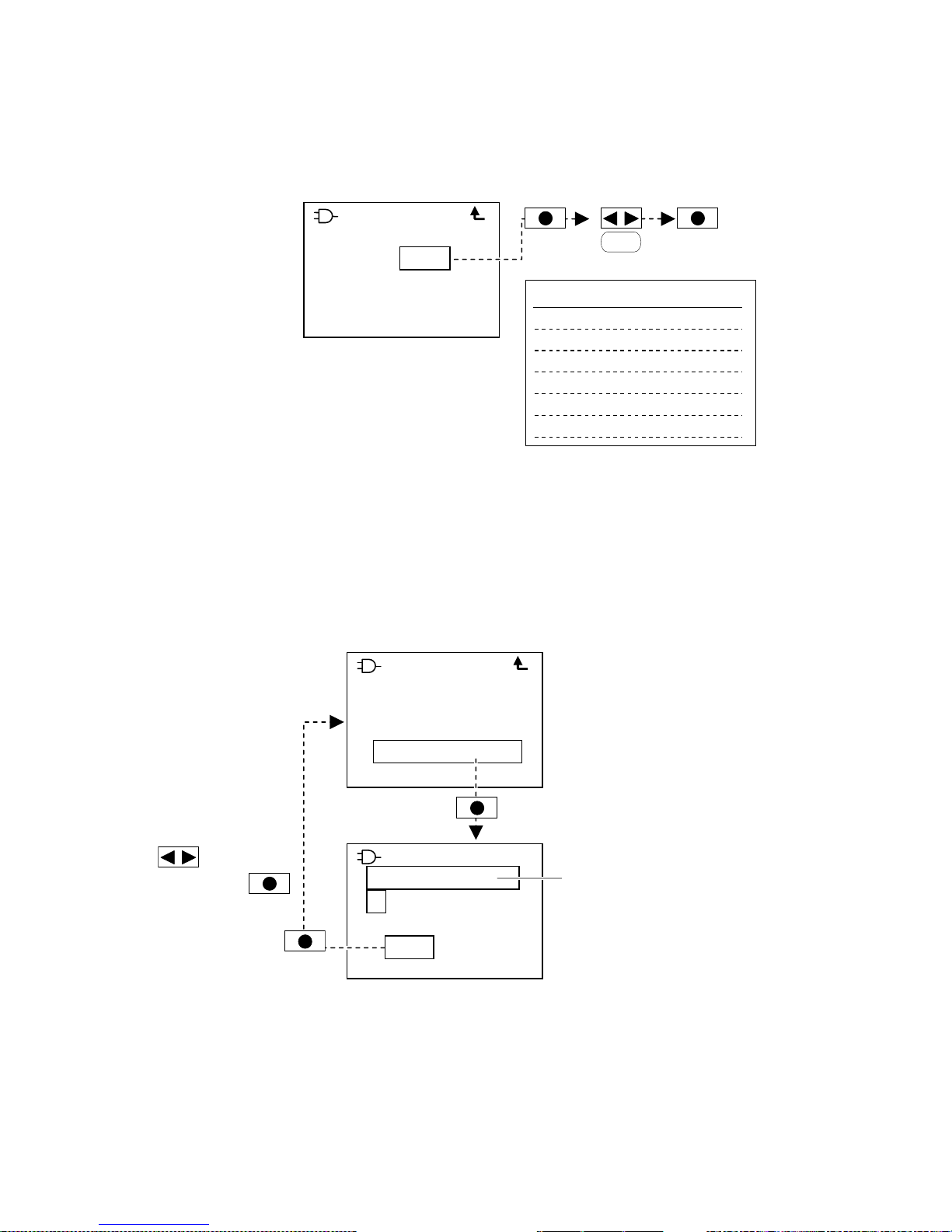
36
10-2-2 Spindle/Beaker Settings
Refer to the "Maximum Measurement Values Guideline Chart" and select the most suitable
spindle and beaker for your application (Cfrom p.42).
10-2-3 Standard Liquid Viscosity Settings
Check the viscosity of the standard liquid by using the temperature conversion chart
included with the standard liquid as reference.
Viscosity will differ, depending on the temperature.
20.0°C
1767. 0
1 2 3 4 5 6 7 8
9 0 . ← →
Back
Enter Q u i t
20.0°C
--Use r C a libr.-Spind l e : A1L
Visco s i t y :
1767. 0 0 m P as
Start
[Calibration Screen]
←→: use the arrows to
move the cursor.
Back: select "Back" to
delete the value to the
left of the cursor.
Input field
Slide
to select a
value, then push
to input the value.
Confirm
N
Select "Quit" to cancel settings and
return to the calibration screen.
N Values up to 2 decimal places can
be input.
20.0°C
--Use r C a libr.-Spind l e : A1L
Visco s i t y :
1767. 0 0 m P as
Start
[Calibration Screen]
Blinking
Confirm
Select one of the items listed below:
Item Spindle Beaker
A1S A1 S:15mL
A1L A1 L:100mL
A2S A2 S:15mL
A2L A2 L:100mL
A3S A3 S:15mL
A3L A3 L:100mL
Page 42
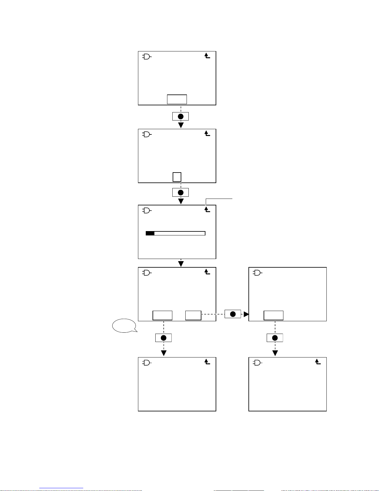
37
10-2-4 Performing User Calibration
The variation (deviation)
will be displayed and a
"beep" will be emitted.
Check the value.
Recommended variation:
within 10.0
If the variation exceeds
10.0, refer to p.39.
Spindle Preparation (Cp.14)
Temperature Sensor
Preparation (Cp.15)
Sample Preparation (Cp.15)
Beaker Setup (Cp.16)
20.0°C
--Use r C a libr.-Spind l e : A1L
Visco s i t y :
1767. 0 0 m P as
Start
20.0°C
--Use r C a libr.-Attac h t h e
spind l e .
OK
20.0°C
--Use r C a libr.-Calib r a t i ng…
Torqu e : 6 4 .0%
20.0°C
--Use r C a libr.-Devia t i o n :6.85
Setti n g s saved.
Enter Quit
20.0°C
--Use r C a libr.-Setti n g s were
not s a v e d .
Exit s e t u p?
Enter Q u i t
20.0°C
--Cal i b r a tion-- User C a l i br.
Reset
[Calibration Menu Screen]
20.0°C
--Use r C a libr.-Spind l e : A1L
Visco s i t y :
1767. 0 0 m P as
Start
Save
Exit without
saving
[Calibration Screen]
[Calibration Screen]
Prepare the spindle,
temperature sensor (only
when using the L Beaker)
and standard liquid.
Beep
N When an error occurs,
"Calibration error." will
be displayed and
"beeping" tones will be
emitted.
Cannot be selected
Page 43
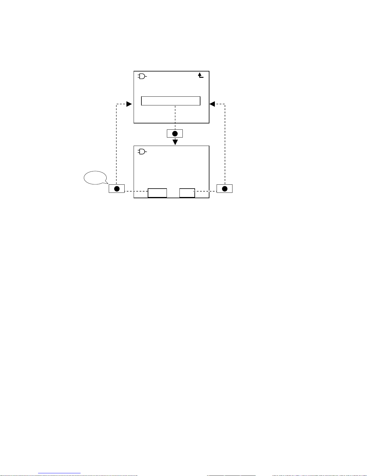
38
10-3 Restore Default Calibration Settings
Calibration settings can be restored to factory default values as described below.
20.0°C
----- R e s e t-----Resto r e f actory
defau l t
setti n g s ?
Enter Quit
[Calibration Menu Screen]
Restore
Exit without
restoring
20.0°C
--Cal i b r a tion-- User C a l i br.
Reset
Beep
Page 44
39
11 Abnormal Measurement Values
If abnormal measurement values occur, perform the following checks as illustrated below.
Checklist Reference Pages and Solutions
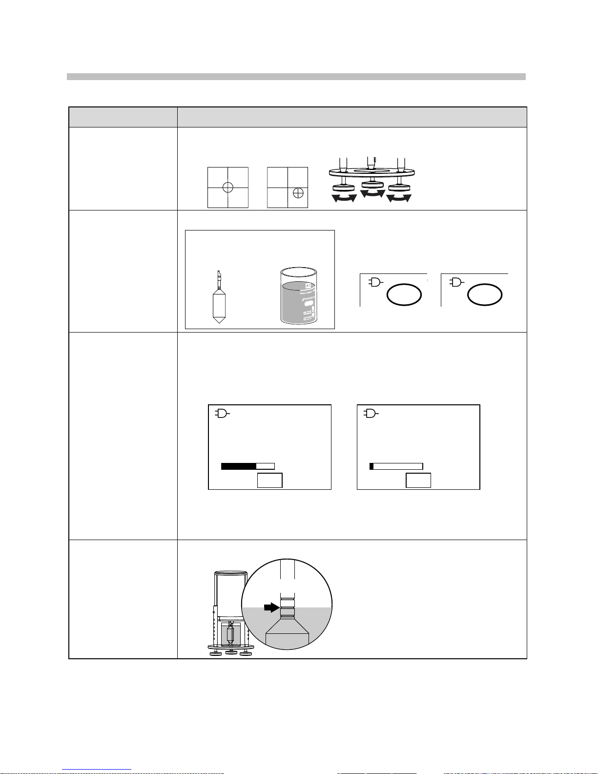
Main unit level
check
Cp.12
Spindle and beaker
combination
setting check
Cp.17
Check that the
torque is within the
recommended
range of 10 to 100%
(and 5.0 to 100.0%
when using Ultra
Low Adapter
(ULA)-Sample
Adapter for Low
Viscosity Sample
(sold separately)).
If the value falls outside of the recommended range, change the
speed, spindle and beaker accordingly to ensure the torque% falls
within the recommended range.
N Speed increase→Torque% increase
Wider spindle→Torque% increase
Smaller beaker→Torque% increase
Sample surface
and spindle
reference line
alignment check
Cp.16
20.0°C
-- A1L 200.0 r p m
558.2
mPas
67.4%
Quit
20.0°C
-- A1L 20.0rpm
570.3
mPas
6.9%
Quit
○
×
Reference line
○
×
[Measurement Screen]
20.0
-- A1L
20.0
-- A3S
example: A1L
Spindle A1
L Beaker
○
×
Use the stand
screws to adjust
the level.
Page 45
40
Checklist Reference Pages and Solutions
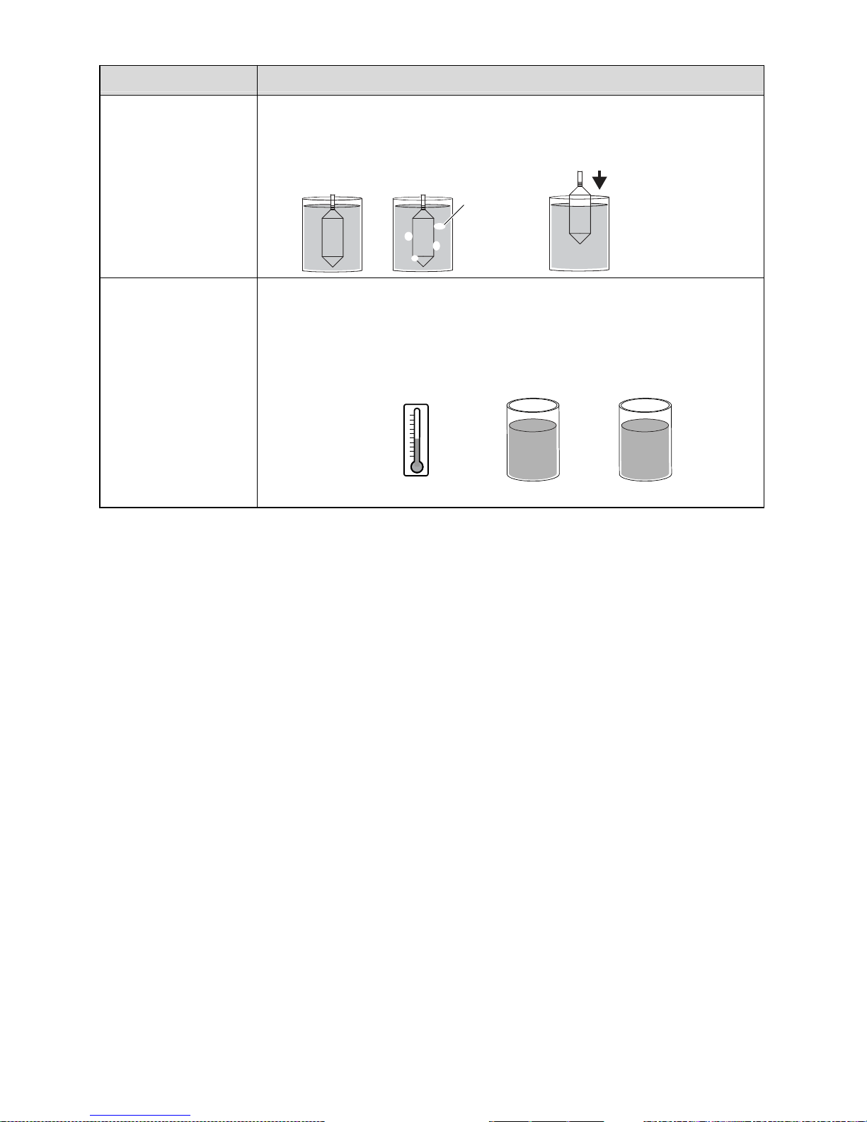
Air bubble check If air bubbles are present, let the sample sit and settle in order to
remove the air bubbles. When the main unit is set up, you can avoid
air bubbles by slowly inserting the spindle in the sample.
Sample
temperature check
Ensure that the sample temperature is fully acclimated to the
ambient conditions (example: Adjust the ambient temperature until it
is stable, then let the sample sit for a while until it has acclimated to
the temperature).
N Viscosity will change depending on the temperature.
○
×
example: ambient
temperature 20˚C
20℃
10℃
○
×
Air bubble
Slowly
Page 46
41
12 Optional Accessories and Replacement Parts
Contact ATAGO or your ATAGO distributor to place an order or for any inquiries.
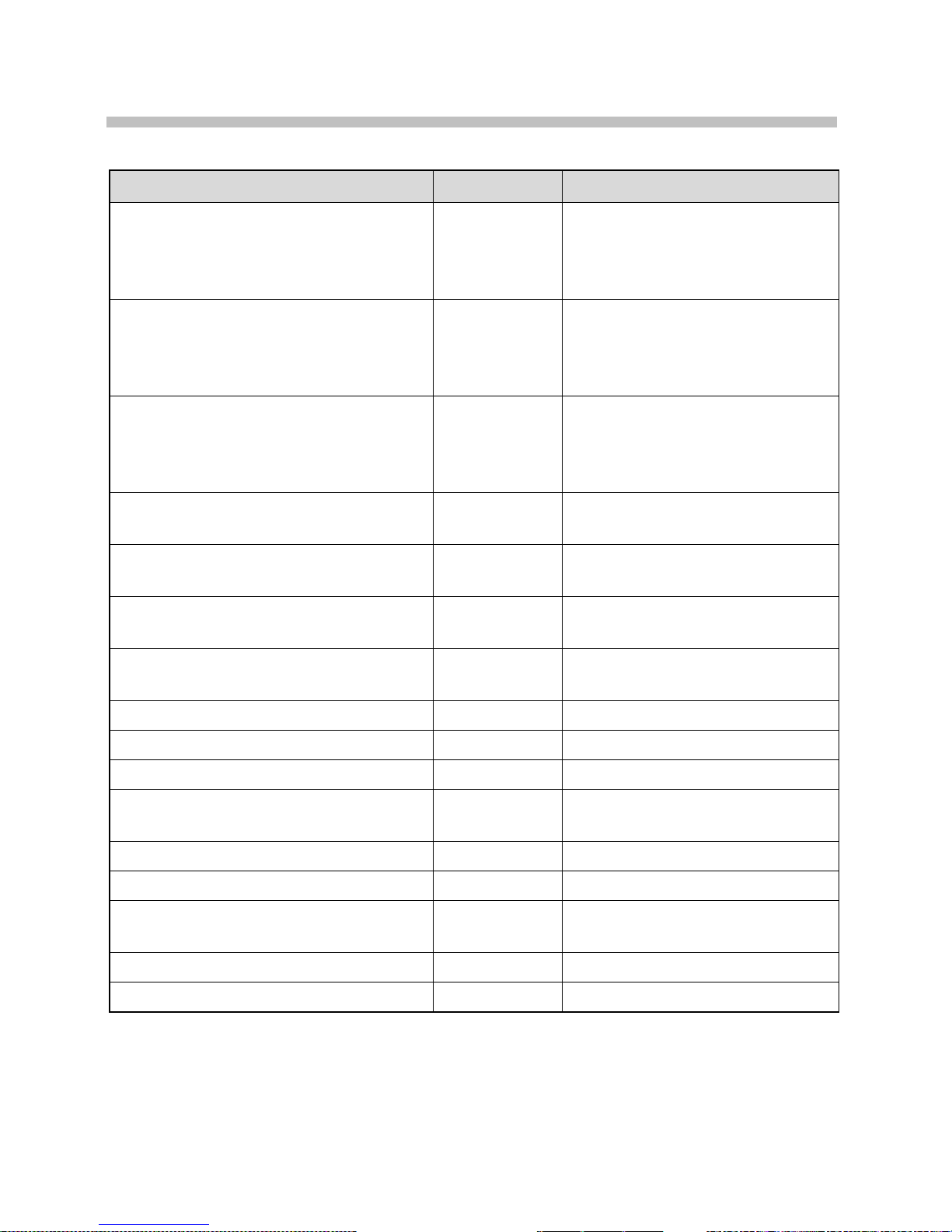
Name Part No. Notes
Standard liquid JS10 RE-
Manufactured by Nippon Grease
Co., Ltd (500mL)
For Ultra Low Adapter (ULA)-Sample
Adapter for Low Viscosity Sample.
Standard liquid JS20 RE-
Manufactured by Nippon Grease
Co., Ltd (500mL)
For Ultra Low Adapter (ULA)-Sample
Adapter for Low Viscosity Sample
Standard liquid JS50 RE-
Manufactured by Nippon Grease
Co., Ltd (500mL)
For Ultra Low Adapter (ULA)-Sample
Adapter for Low Viscosity Sample
Standard liquid JS200 RE-89016 Manufactured by Nippon Grease
Co., Ltd (500mL)
Standard liquid JS500 RE-89017 Manufactured by Nippon Grease
Co., Ltd (500mL)
Standard liquid JS1000 RE-89018 Manufactured by Nippon Grease
Co., Ltd (500mL)
Standard liquid JS2000 RE-89019 Manufactured by Nippon Grease
Co., Ltd (500mL)
Spindle A1 RE-77104
Spindle A2 RE-77105
Spindle A3 RE-77106
Ultra Low Adapter(ULA)-Sample
Adapter for Low Viscosity Sample
RE-
For measuring low viscosity
samples (1~2,000mPa・s)
S Beaker (15mL) RE-79100
L Beaker (100mL) RE-79101
Cup adapter (with 100pcs cups) RE-78141 with 50 paper cups and 50
plastic cups
Paper cups (90mL 100pcs) RE-79102 for Cup adapter
Plastic cups (90mL 100pcs) RE-79103 for Cup adapter
N Ultra Low Adapter will allow to measure low viscosity samples (1~2,000mPa・s). It
only requires small amount of sample volume (16mL) to measure. (Only applicable
for samples with aforementioned viscosity measurement range.)
N By using the cup adapter, measurements can be taken in a disposable container in
place of a glass beaker.
The cup adapter eliminates the hassle of cleaning glass beakers after measurement.
Page 47
42
13 Supplementary Material
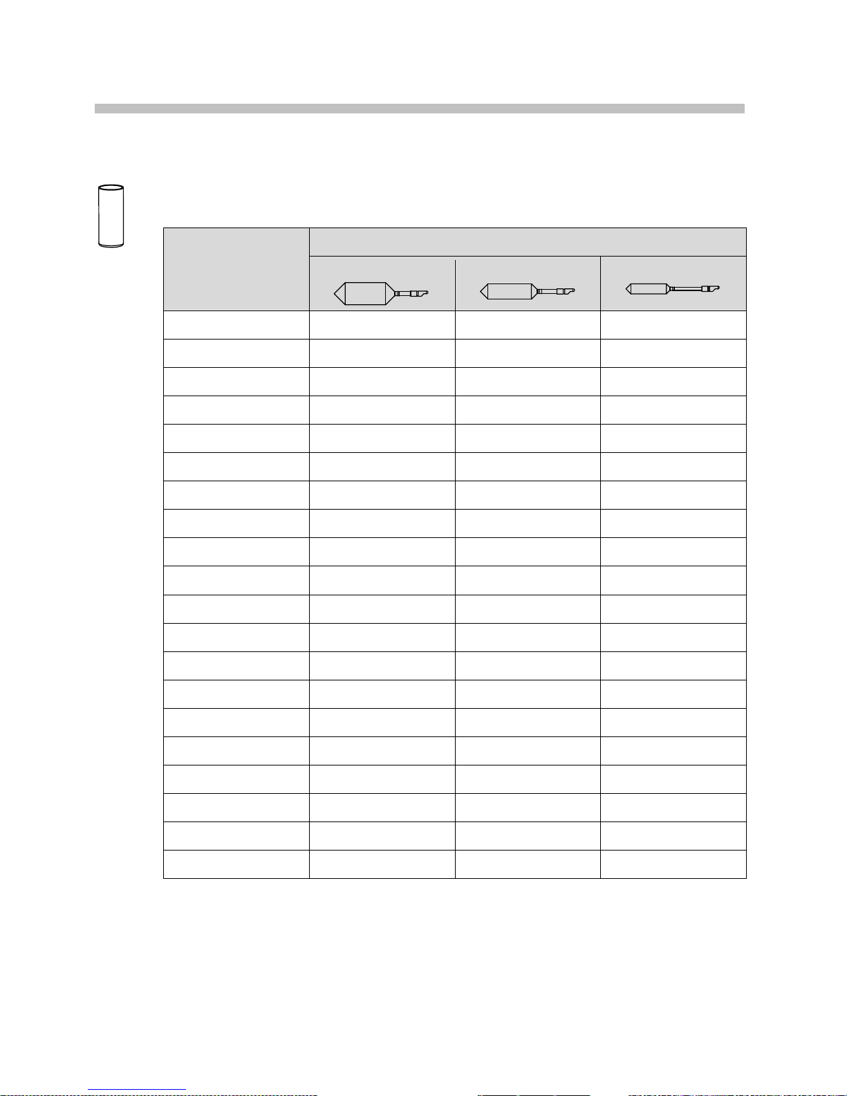
13-1 Maximum Measurement Values Guideline Chart
S Beaker (15mL)
Unit: mPa・s (cP)
Spindle
rpm
A1
A2
A3
0.5 180k 600k 2.1M
0.6 150k 500k 1.7M
1 91k 300k 1M
1.5 60k 200k 700k
2 45k 150k 520k
2.5 36k 120k 420k
3 30k 100k 350k
4 22k 75k 260k
5 18k 60k 210k
6 15k 50k 170k
10 9.1k 30k 100k
12 7.5k 25k 87k
20 4.5k 15k 52k
30 3k 10k 35k
50 1.8k 6k 21k
60 1.5k 5k 17k
100 910 3k 10k
150 600 2k 7k
200 450 1.5k 5.2k
250 360 1.2k 4.2k
m example: 4.5k = 4,500
example: 1.7M = 1,700,000
Page 48
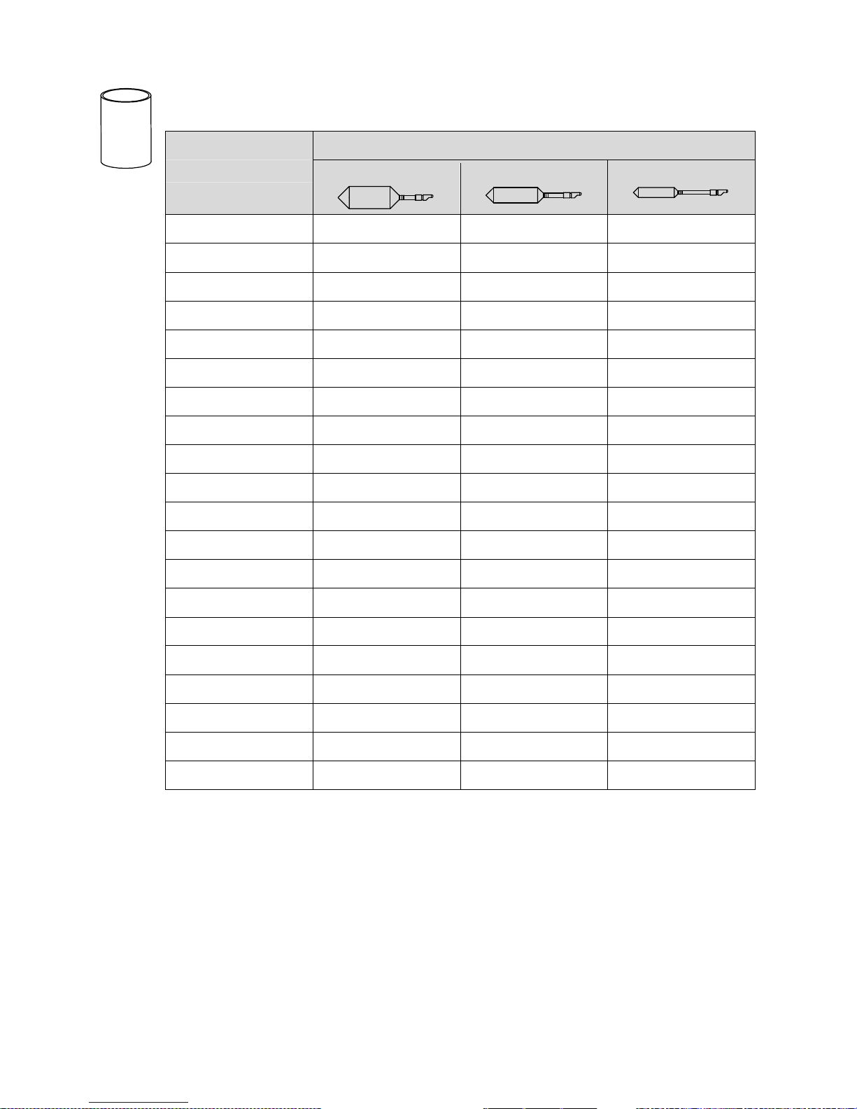
43
L Beaker (100mL)
Unit: mPa・s (cP)
Spindle
rpm
A1
A2
A3
0.5 320k 740k 2.3M
0.6 260k 610k 1.9M
1 160k 370k 1.1M
1.5 100k 240k 770k
2 80k 180k 570k
2.5 64k 140k 460k
3 53k 120k 380k
4 40k 92k 280k
5 32k 74k 230k
6 26k 61k 190k
10 16k 37k 110k
12 13k 30k 96k
20 8k 18k 57k
30 5.3k 12k 38k
50 3.2k 7.4k 23k
60 2.6k 6.1k 19k
100 1.6k 3.7k 11k
150 1k 2.4k 7.7k
200 810 1.8k 5.7k
250 640 1.4k 4.6k
m example: 4.5k = 4,500
example: 1.7M = 1,700,000
Page 49

44
14 Warranty, Repair and Calibration
The instrument is warranted for one year from the date of purchase. Repair services will be
performed free of charge while the instrument is under warranty. However, this warranty is
void if the instrument shows evidence of the following:
• Having been disassembled by unauthorized personnel.
• Having been misused and/or operated outside the environmental specifications.
Repair services are available for a fee after the warranty expires.
Replacement Parts
Replacement parts are necessary to maintain performance of the instrument.
Replacement parts are generally available for 7 years after a model is discontinued.
However, please be aware that replacement parts may become unavailable from the
suppliers within the 7-year period. Contact ATAGO, an authorized ATAGO distributor, or
the original seller.
*Any repair services that require disassembly must be performed at an authorized ATAGO
service center.
Calibration Recommendation
In accordance with the ISO quality management systems, ATAGO provides calibration
services that comply with HACCP and GMP standards (only available for ATAGO products;
a fee will be charged for this service).
The following documents will accompany an instrument after calibration:
Calibration certificate, traceability certificate, and traceability diagram.
Please have the serial number information ready when contacting us.
Page 50
45
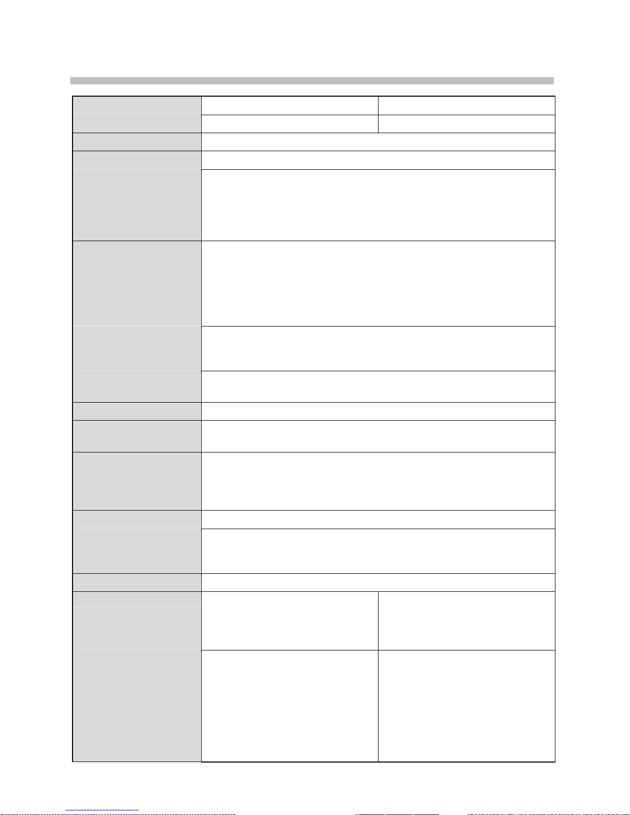
15 Specifications
Product name VISCO VISCO-895
Cat. No. 6800 6820
Measurement Scales Viscosity・Temperature・Torque%
Display Items Viscosity・Temperature・Torque%・Speed・Spindle and beaker combination
Measurement Range Viscosity: A1 50 to 200,000mPa・s / 50 to 200,000cP
A2 100 to 600,000mPa・s / 100 to 600,000cP
A3 500 to 2,000,000mPa・s / 500 to 2,000,000cP
Torque: 0.0 to 100.0% (recommended torque: 10.0 to 100.0%)
Temperature: 0.0 to 100.0℃/32.0 to 212.0°F
Resolution Viscosity: lower than 100mPa・s 0.01mPa・s
100mPa・s or higher lower than 10,000mPa・s 0.1mPa・s
10,000mPa・s or higher 1mPa・s
Torque: Lower than 10% 0.01%
10% or higher 0.1%
Temperature: 0.1℃/0.1°F
Measurement Accuracy Viscosity: ±1% of Maximum Viscosity
(Refer to the "Maximum Measurement Values Guideline Chart," from p.42)
Temperature: ±0.2℃/±0.4°F
Speed 0.5 to 250rpm
Number of Speeds: 20
Language Japanese / English
Sample Temperature
Range
10.0 to 40.0℃ / 50.0 to 104.0°F
Environmental
Conditions
• Use the instrument where the temperature is between 10 to 40℃
• Use the instrument at an altitude below 2,000m (above sea level).
• Use the instrument under the condition where humidity is 80% at 31℃
or lower, falling linearly to 50% at 40℃.
Computer Output Output: USB Mini-B - PC
Power Supply LR6 / AA alkaline batteries (x4)
AC adapter input: AC100 to 240V. 50/60Hz, 0.3A
output: 9V, 0.5A.
Battery Life ( Approx.) Approx. 7 hours (continuous operation at 60rpm)
Material Main unit: SUS316L, aluminium
Legs: SUS304
Stand: SUS304
Stand screw: SUS303
Main unit: aluminium
Legs: aluminium
Stand: aluminium
Stand screw: aluminium
Dimensions and Weight Main unit: 120(W)x120(D)x
200.6(H)mm
1.2kg (excluding
batteries, spindles
and temperature
sensor)
Stand+screw: 0.5kg
Small volume beaker attachment:0.1kg
Main unit: 120(W)x120(D)x
200.6(H)mm
0.895kg (excluding
batteries, spindles
and temperature
sensor)
Stand+screw: 0.27kg
Small volume beaker attachment: 0.1kg
 Loading...