

Page 1

Rev: 02/15/004
7 day, Single Channel Digital Wireless Programmer and Room Thermostat –
Part No. CT200001
The digital wireless programmer and room thermostat is a 7 day radio frequency (RF) wireless
thermostat / timer, which communicates with a receiver designed to fit in the clock aperture of the
boiler control panel. The unit can be pre-programmed to provide maximum and minimum room
temperature control. Each day can be programmed with the same – or different – time periods. The
programme can be temporarily or permanently overridden to increase or decrease the desired
temperature setting.
The batteries should operate the unit for approximately 18 months to 2 years depending on the
number of switching operations etc. Only good quality alkaline batteries should be used. When the
batteries need replacing, a low battery symbol will be displayed. After replacement, all the
programmes and temperature settings remain stored and no resetting is required.
Note: If the batteries are not replaced and no valid signal is received from the Transmitter, the
Receiver’s neon light will flash every 0.5 seconds. After 1 hr the boiler will operate in ‘Emergency
mode’ (heating on for 4 min. and off for 9 min.) until the batteries are replaced.
Note; always press the reset button after removing or replacing the batteries.
This timer is suitable for installation as a time controller for:
ATAG iC 24 Combi
ATAG iC 28 Combi
ATAG iC 36 Combi
ATAG iC 40 Combi
ATAG Economiser 27
ATAG Economiser 35
ATAG Economiser 39
ALWAYS switch off and disconnect the electricity supply to the appliance before installing the
programmer. Merely switching the boiler ON/OFF switch to 'OFF' will still leave a live feed to
the boiler.
WARNING.
This unit must be installed by a skilled electrician
in accordance with the current I.E.E. Wiring Regulations.
Page 2
Rev: 02/15/004
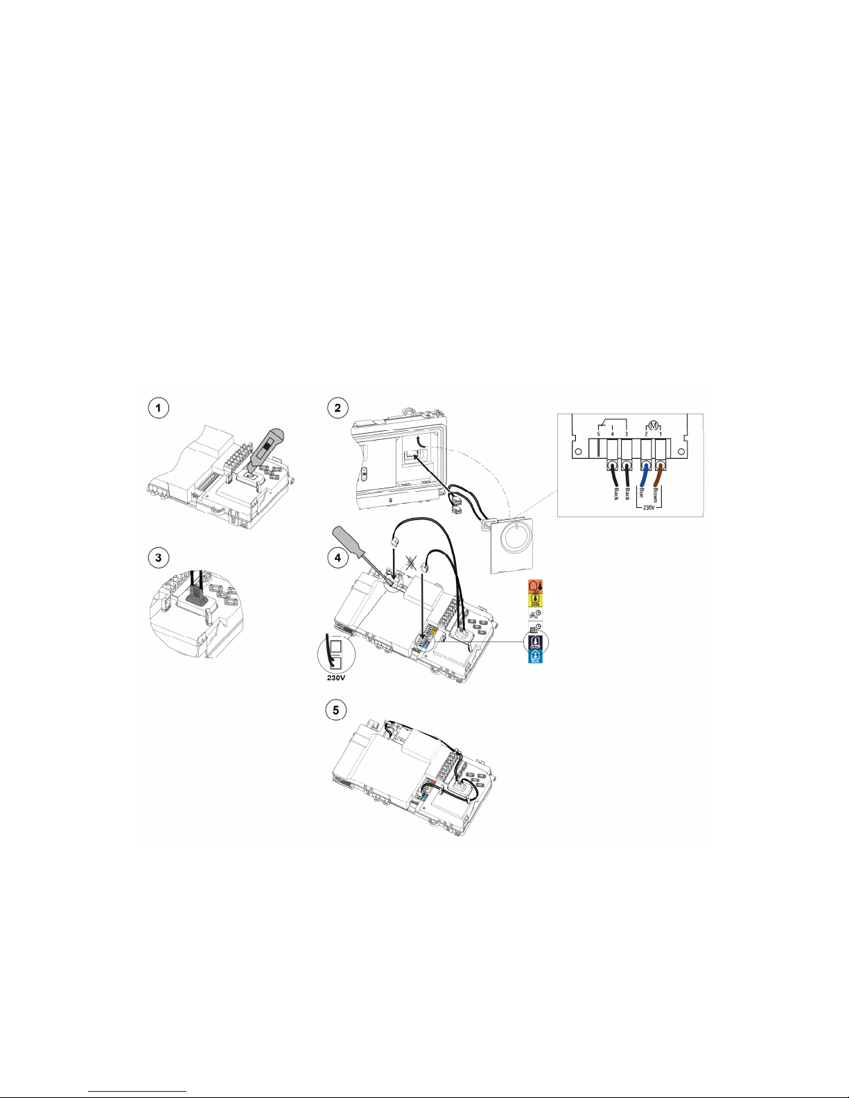
1. To install the receiver
1. Turn the power off to the boiler
2. Remove the boiler front panel and swing the control panel into the service position. Refer to
boiler Installation & Servicing Manual.
3. With a sharp knife, cut out the small plastic cutaway (fig 1) to allow the wires to go through
and the wires grommet to secure into position.
4. Remove the blank clock control panel and feed the wires through to the back (fig 2). Fit the
new receiver front panel into the facia of the boiler.
5. Check the wires grommet is in the correct position (fig 3).
6. Fit the black connector with two black wires onto the volt free connection next to the black
label with a house symbol and on / off below (fig 4).
7. Remove the small electrical blanking cover and fit the White connector with brown and blue
wires to the 230v ac connection terminals (fig 4).
8. Secure the wires in to wire clips as shown in fig 5.
9. Swing the control panel back up into operating position.
10. Power up the boiler and check for correct operation.
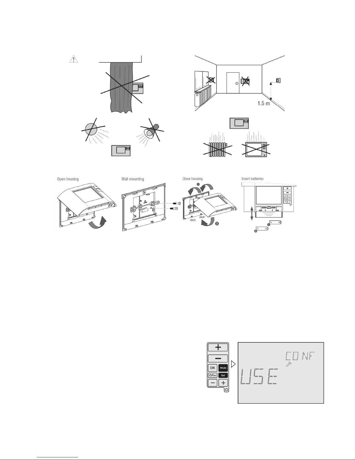
1. Installation of Transmitter
Locate and fit the transmitter to the wall 1.5m from the floor, taking into consideration where
not to position the transmitter as shown the next diagram.
The following can reduce, deflect or block radio frequency signals between the transmitter
and receiver.
a. Steel reinforced walls.
b. Large metallic objects e.g. kitchen appliances, filing cabinets, mirrors etc.
c. Maximum distance between Receiver and Transmitter is:-
i. In open air 50m.
ii. In building 20m to 30m depending on radar obstruction.
Page 3
Rev: 02/15/004
Transmitter Position
2. Commissioning
The Digital Thermostat and Receiver are pre commissioned (paired) at the factory.
However, if the Receiver or Transmitter has been changed then full commissioning will be required as
follows:-
1. Press and hold the black button of the receiver until the
LED light has flashed twice. Release the button and the
LED light will remain illuminated.
2. Press and hold MODE-button and SET-button of the
transmitter at the same time for more than 3 seconds to
enter into the User menu. Then press the OK-button until
RF Comm is displayed.
Remove wall
mounting rear panel
from Transmitter
Secure rear panel
to wall. Note: There
must be a top
clearance of at least
80 mm to allow the
front cover to be
raised upwards
Re-assemble
Transmitter to rear
panel
Slide the front cover
up, open the battery
compartment and fit
the batteries.
Ensure the batteries
(2 x 1.5V L26/AA)
are correctly fitted
Page 4
Rev: 02/15/004
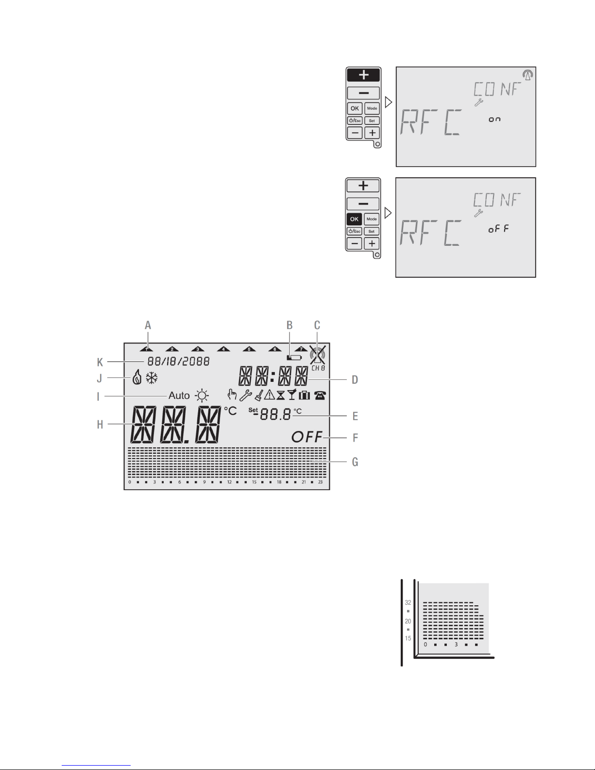
3. Press upper + button (– button disables the RF signal)
to enable a continuous RF signal. The receiver LED will
go out as soon as a signal from the transmitter is
received. Then press the OK-button, the radio link
between transmitter and receiver is now established.
Press the ESC-button to return to Auto mode.
4. Receiver: When operating in heating mode and an ON
signal is received, the LED illuminates continuously.
When an OFF signal is received the LED will flash
intermittently.
4. Display
Operating and adjustment
Operating information
• Flashing texts signal the need for an entry. If no button is pressed for 2 minutes, the device reverts
to the Automatic mode.
• All settings need to be confirmed with OK.
• All settings saved will remain in the memory.
• The histogram shows the programmed temperature profile
7 – 14°C = displayed as one segment
15 – 24°C = one segment displays 1°C
over 24°C = one segment displays 2°C
A Current week day
B Battery
C RF signal
D Current time
E Set temperature
F Off mode
G Histogram over 24 hours
H Current temperature
I Operating mode
J Status indication
K Current date
Page 5
Rev: 02/15/004
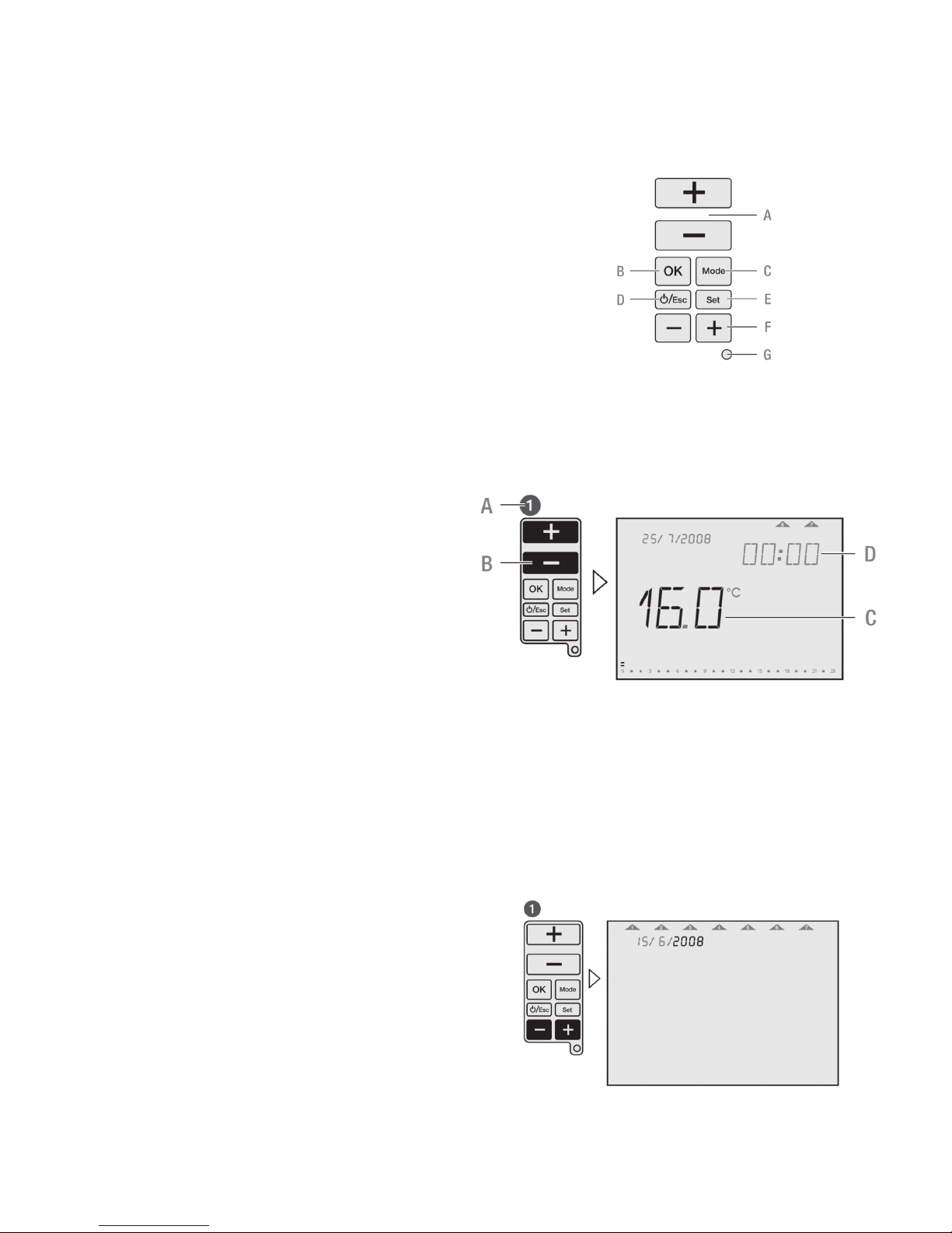
Function Keys
A. +/– buttons used to increase/decrease temperatures.
B. OK-button to confirm settings and go to the next step.
C. MODE-button to select from the available operating modes.
D. ESC-button used for ON/OFF, go one step back in menu or
return to main menu by pressing the button more than 3 seconds.
E. SET-button for settings following commissioning.
F. +/– buttons used to increase/decrease hours, days and events.
G. RESET-button to return to factory settings. The programs are
retained in the case of a reset. The date and time must be set
again. Press reset button with a blunt object (pen).
Configuration
General information
For the use of this manual you must observe the following information:
A Sequence of operation
B Pressed buttons are shown in black.
C Flashing elements are shown in black
D Fixed elements are shown in grey
• Buttons which can be pressed during an
action are shown in black. The related display
is also shown in black.
• Follow exactly the numbers of the sequence
of operation.
• The configuration of the device is described
based on configuration.
• After starting the device for the first time, follow the menu for a correct configuration of the device.
• Following commissioning, you can also change the configuration by pressing the SET-button.
Initial start-up
Set date and time
Sequence for setting the date and time during initial start-up.
15/6/2008 appears as factory default.
To set the date and time after initial start-up press the
SET-button, then choose Date or Time Menu with the
upper +/– buttons and confirm with OK.
Page 6

Rev: 02/15/004
5. The time is set in the same way as the date.
Programming
Sequence for specifying programs during initial start-up
To specify programs after initial start-up press the SET-button, then choose the Prog menu with the
upper +/– buttons and confirm with OK.
Page 7

Rev: 02/15/004
Choose between:
7 days – one programme
5-2 days – one program per day block
1-7 days – each day an individual program
free block formation – one program per day block
Select program
Each weekday or day block must be allocated a program P1, P2, P3, P4 (pre-defined) or Pd (user
defined).
Pd
User-defined program.
During initial start-up, program will be shown with 15ºC from 00:00 to 23:59 PM.
Page 8

Rev: 02/15/004
If you wish you can modify the pre-defined programs. Use the upper +/– buttons to increase/decrease
the temperature of each segment by 0.5°C. Use the lower +/– buttons to go forward/backward 30
minutes each time and copy the selected temperature value.
Settings
After commissioning you can change the date, time, temperature and time programming. By pressing
the upper +/– buttons you jump to the different menus.
1-3 = adjustment of date
2-3 = adjustment of time
3-3 = adjustment of time and temperature programming
3. You are now able to adjust the date as described in the initial start-up. The sequence of setting the
time is similar to the method for setting the date.
Page 9

Rev: 02/15/004
With the lower +/– buttons you can choose days or day blocks for programming and confirm with
OK. Go to operation number 6.
By pressing the OK-button you can choose between the pre-defined programs P1 – P4 or the userdefined program Pd. Go to operation number 7.
By pressing the lower +/– buttons you can go
through the program to check it.
For editing the program, use the upper +/– buttons
to increase/decrease temperature in each segment
by 0.5°C. Use the lower +/– buttons to go
forward/backward and copy the selected
temperature value.
Page 10

Rev: 02/15/004
Operating modes
Set operating modes
Follow the sequence for selecting the desired operating mode. The operating modes in the device
appear in the same order as described here.
Press and hold the ESC-button for 3 seconds to return to Auto mode.
Auto
Symbol:
After each programming session, the device automatically returns to the Auto mode. The predefined
or user-defined program run here.
Page 11

Rev: 02/15/004
Manual-ECO-Fix
Symbol:
Manual-ECO-Fix mode calculates an average temperature of the actual program. This temperature is
is kept for the whole day until any user‘s intervention is made. To return to Auto mode, press OK.
The average temperature is the starting point for increasing or decreasing the desired temperature,
pressing upper +/– buttons. The new temperature set value is then, after 3 sec., set for all day long.
Example: 4 different temperatures in the actual program (e.g. 17°C, 19°C, 20°C and 22°C).
Average temperature is then 19.5°C.
Cleaning mode
Symbol:
This mode sets the device into OFF mode for a pre-set time of 2 hours. During the cleaning time,
remaining time is shown until running mode elapsed. After the Cleaning mode is elapsed, the device
returns into Auto mode.
To end Cleaning mode early, press ESC-button for more than 3 seconds.
The anti-freeze protection is granted.
Page 12

Rev: 02/15/004
Countdown mode
Symbol:
This function runs into a desired set temperature during certain period of time. Adjustable period of
time is 1 – 23 hours. After the time is elapsed, the device returns into OFF mode (Anti-freeze
temperature is kept). During the Countdown mode, remaining countdown time is indicated.
Example: The device shall be run into OFF mode after 4 hours.
To end Countdown mode early, press ESC-button for more than 3 seconds.
Party mode
Symbol:
This mode allows the user to set a desired temperature during defined period of time. Adjustable
period of time is 1 – 23 hours. After the time is elapsed, the device returns into the mode before the
Party mode was activated. During the Party mode, the rest of the time is indicated.
Example: The temperature shall be set for 6 hours on 24°C.
To end Party mode early, press ESC-button for more than 3 seconds.
Page 13

Rev: 02/15/004
Holiday mode
Symbol:
This function runs into a desired set temperature during certain period of time. Adjustable period of
time is 1 – 90 days. After the time is elapsed, the device returns into the mode before the Holiday
mode was activated. During the Holiday mode, the rest of the days is indicated.
Example: The temperature shall be set for 16 days on 13°C.
To end Holiday mode early, press ESC-button for more than 3 seconds.
Operating status
Manual override
Symbol:
While the sliding cover is closed, you can temporarily adjust the temperature in the current period with
the upper +/– buttons. It is not necessary to confirm the setting with OK. The setting will remain as
temperature set value until the next programmed change (time and temperature) appears.
To return into Auto mode, press and hold upper +/– buttons for 3 seconds, or open the sliding cover
and press OK-button.
Page 14

Rev: 02/15/004
OFF mode
Symbol:
This mode switch off the device completely. To
activate this mode press and hold ON/OFF/ESCbutton for more than 5 seconds. To leave this
mode press and hold the ON/OFF/ESC-button
again for more than 5 seconds.
The anti-freeze protection is granted.
Low battery
Symbol:
A low battery level is indicated with the battery icon in the
display. Please change the batteries. If batteries are not placed
or are installed in the wrong polarity, <Bat> text will appears on
display until they are placed or installed in the right polarity.
If the battery goes completely empty, the programming is
protected.
User menu/Configuration
Symbol:
Press the MODE-button and SET-button at the same time until User menu is shown in the display.
To go to previous menu press ESC-button. It is possible to adjust:
• RF commissioning (RFC): Enable/disable
continuous radio signal
• Offset (OFS): Possibility to adjust/modify the
measured temperature (-5°C...+5°C)
• Summer/Winter time (SWT): enable/disable
automatic summer/winter time change
• Time Format (TMF): possibility to change time
format into 24 hours or 12 hours (default: 24
hours)
• Restore Default (DFL): Restore values to
factory default status.
Use lower +/– buttons to navigate through menus.
Use upper +/– buttons to change values and OK to confirm.
Page 15

Rev: 02/15/004
Installation menu
Symbol:
To access this Configuration menu, press the MODE-button, the OK-button and SET-button at the
same time until Installer menu is shown in the display. Press ESC-button to go to previous Menu.
The adjustments in this menu are only for experts.
All possibilities for adjustment are shown with a self-explaining, floating real text in the display.
Use lower +/– buttons to navigate through menus.
Use upper +/– buttons to change values and OK to confirm.
Following adjustments are possible:
High Temp (HIT): set maximum temperature value for programming from low temperature
value up to +32°C (default: +32°C)
Low Temp (LOT): set minimum temperature value for programming from +7°C up to high
temperature value (default: +15°C)
Frost protection (FRT): set anti-freeze minimum temperature value from +3°C to +7°C (default: 5°C)
Regulation (REG): possibility to select between PID or 2 points regulation (default: PID)
Differential (DIF): possibility to modify differential value from 0,1 K to 0,9 K (default: 0,4 K)
Keypad Lock (LOK): enable keypad to protect against non authorized interventions
To enable/disable the keypad lock press and hold MODE- and ESC-button
for more than 3 seconds.
Operating hours (OPT): this feature shows total operating running time (max. 99.999 hours)
Battery Level (BAT): battery charge level is shown on display
Warranty
This control is guaranteed against manufacturing defect for a period of 12 months from the date of
installation.
This Guarantee does not cover replacement of batteries or cosmetic damage to the controller.
ATAG Heating Technology Ltd
47 Castle St, Reading, Berkshire, RG1 7SR
Tel: 0800 254 5061
www.atagheating.co.uk
 Loading...