

Page 1

User
Manual
Page 2
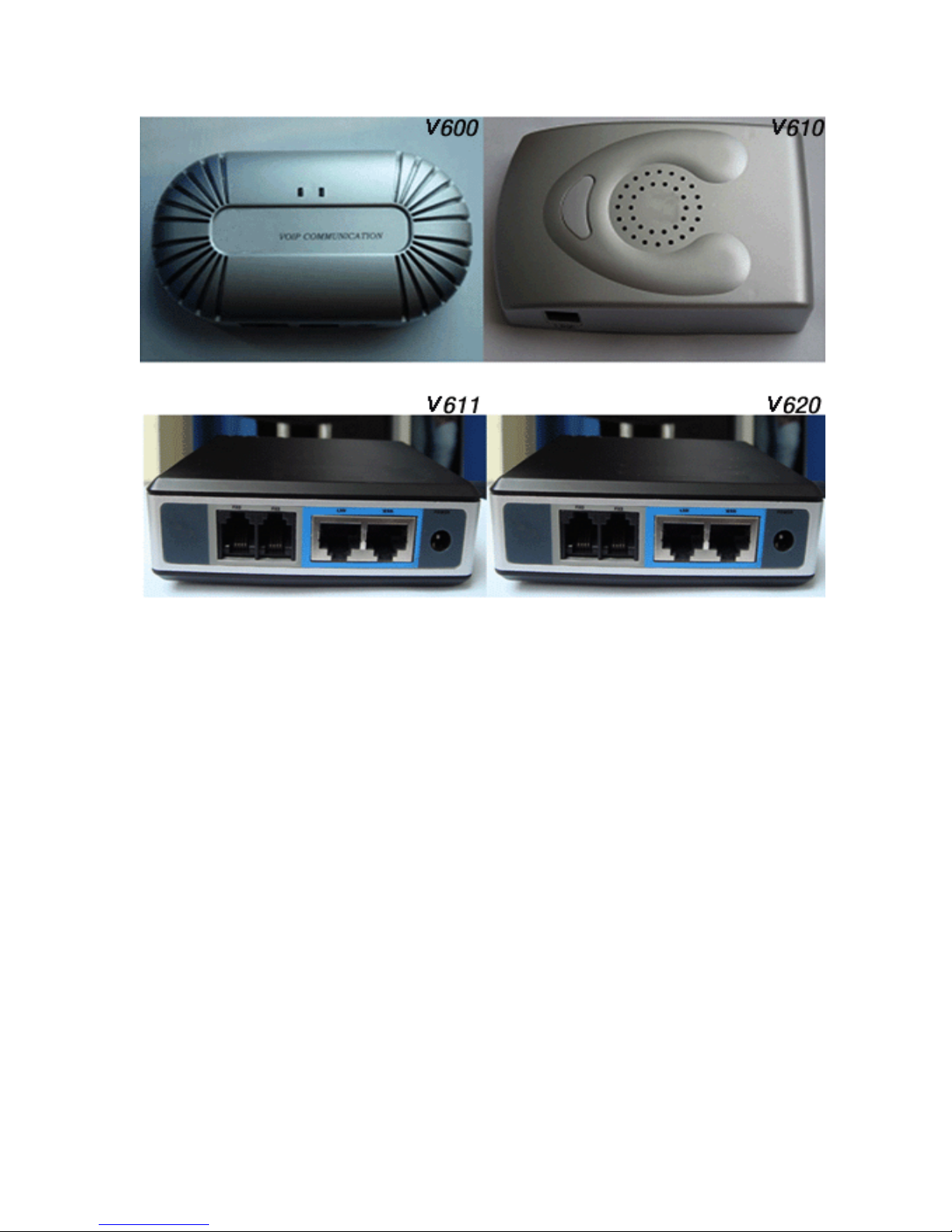
1
Contents
W e l c o m e … … … … … … … … … … … … … … … … … … … . . 3
CHAPTER 1 Installation………………………..……………………………….4
CHAPTER 2 Production Summarize……………………..…………………5
I、Key Features……………………………………………………………………….5
II、Technical Parameter……………………….………………….………..…………5
CHAPTER 3 Basic Manipulation………..…….………………..…………….6
I 、 K e y s t r o k e s A n d V o i c e
P r o m p t … … … … … … … … … … . . … … … . . … … . … … … … … 6
II、Make a Call……………………………………………..…………….…………….8
i、How to Make a PSTN Call ……..………………………………………………8
i i 、 H o w t o M a k e a V o I P
Page 3

2
C a l l … … … … . … … … … … … … . . … … … … … … … . … … … 8
iii、Direct IP Call……………..…………………………………………………….9
III、Call Features ………………….………………………..…………..……………11
IV、Call Function………..……………….………………………………………….12
i、 Blind Transfer …………………….……………………………………………12
ii、Attended Transfer …………….……………………………………………13
iii、Conference Call ……………………………………………………….………13
iv 、 VoIP-to-PSTN
Calls………….………………………………………………….14
v、PSTN-to-VoIP Calls……….………………..………………………..………….14
vi、Route Calls to PSTN………………………………………………….…………14
vii、Fax ……………………………………………………………………..………15
viii、LED Light……………..……………………………………..………………15
CHAPTER 4 Configuration guide ……..…………………..………………16
I、Configuring Wan IP Through Voice Prompt……………………….…………16
i、Dhcp Mode….. ……………………………………………………………16
ii、Static IP Mode …….…………………………………………………………17
II、Configuring With Web Browser ……………..…….…………………………17
i、Access the Web Configuration Menu ….…..……………….………………18
ii、End user Configuration ………………………….…………………………18
III、Status……………………………..…………………………………….……...18
IV、Basic Optino…….……………….…………………….………………….……18
i 、L a n S et t i ng s … …… … ……… …… …… .… …… …… …… …… …. 18
ii 、 Wa n Set ti n gs … ……… ……… …… ….… .… ……… ……… ……… . 19
iii、Nat Settings……………………………….….………………………………21
iv、Other Settings……..……………………………………………………………22
v、 Call Settings(V611Fxo port)………..……..……………………………………22
V、Super Options……..…….…………………………………………………..24
i、 SI P S ett in g s… …… …… …… ……… …… ……… …… ….… ……… .2 4
ii、Audio.Settings ………………..………………………………….…………...28
iii、Dial.Settings ……………………………………………………….………...31
iv、Other Settings ………………..………………………….…………….……….32
v、Fxo Port --->Phone Feature……...…………..…….….……………........……….34
CHAPTER 5 Restore Factory Defaults Setting………..…………………37
CHAPTER 6 Upgrade………………………………………………….……...…..38
CHAPTER 7 Ordinary Quality Checking……….…………………………39
CHAPTER 8 FAQ………………………………..………………….......................39
Page 4

3
welcome
The IP voice gateway is the new product. It follows the standard of the
SIP2.0, and is compatible other SIP products or software.
The IP voice gateway is an all-in-one VoIP integrated access device that
features superb audio quality, rich functions, and high level of integration,
compactness and ultra-affordability.
Page 5

4
CHAPTER 1 Installation
What’s in ATA package?
1)One ATA
2)One universal power adapter
3)One Product Enchiridion
4)One Ethernet cable
5)One phone line
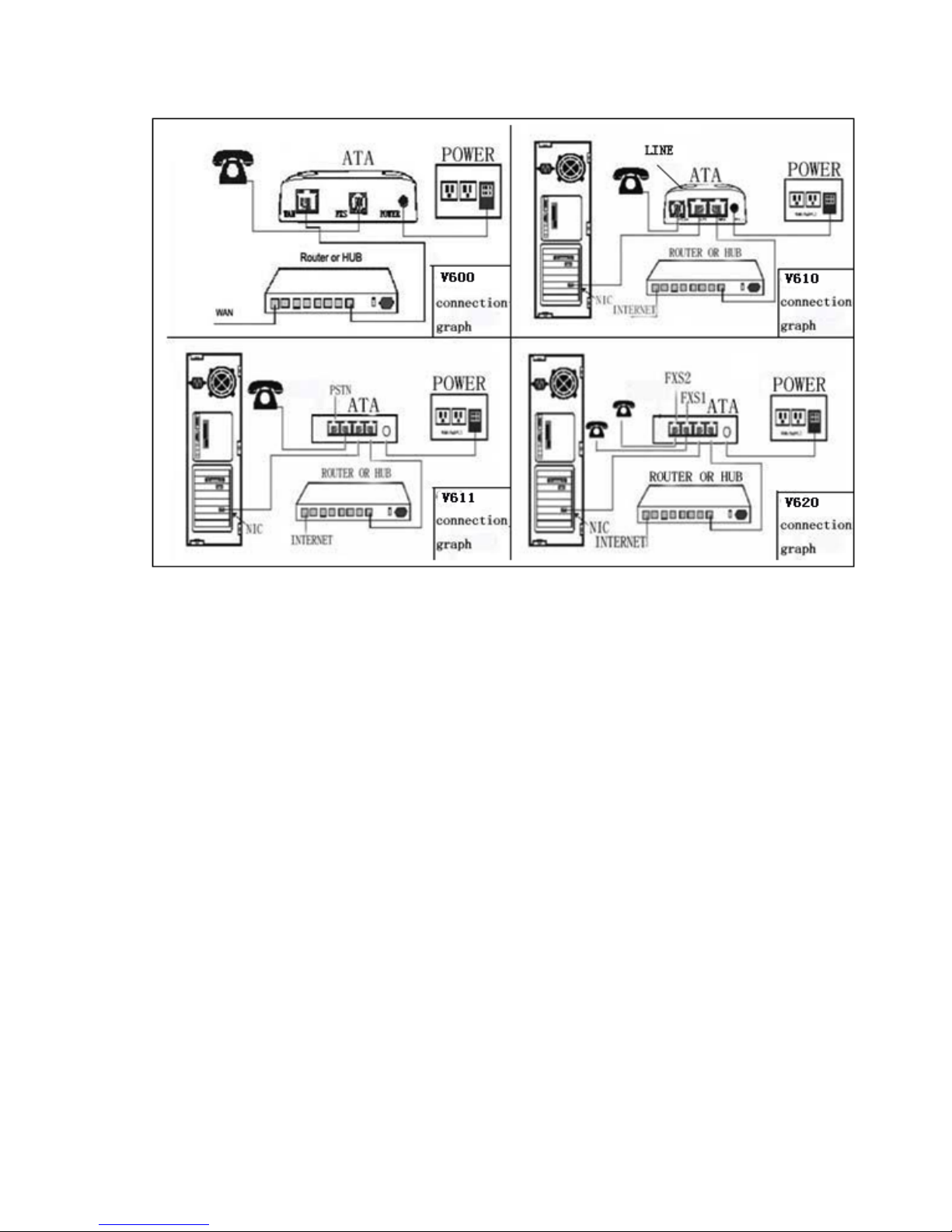
Interconnection diagram of ata
Page 6
5
WARNING:
Please do not try to use other power adapter or we would not bear the responsibility to
the defective products.
Changes or modifications to this product not expressly approved by our company, or
operation of this product in any way other than as detailed by this User Manual, could
void your manufacturer warranty.
CHAPTER 2 Production Summarize
I、 Key features
• Support SIP2.0 (RFC3261), TCP/UDP/IP, RTP/RTCP, HTTP, ICMP,
ARP/RARP, DHCP, NTP, PPPoE, STUN and TFTP etc;
• Inside Rooter、NAT、gateway and DMZ Port transmit;
• Support the PSTN making or receiving calls (by the FXO Port);
• Use the DSP CNOS chip to keeping a wonderful audio-quality,
advanced shaking control, and the technology of hiding the lost
massage;
Page 7

6
• Support kinds of voice coding, including G.711 (a-law and u-law)
G.723.1 (5.3K/6.3K) G.726 (40K/32K/24K/16K), G.729A/B, and
iLBC;
• Support incoming call on show, restricting, and holding,
disconnection, call transfer, call divert, DTMF, dialing project, etc;
• Support conference call;
• Support passing through and T.38 fax, voice restrain and jerquers,
CNG, echo restrains (G.168), AGC, and DIGEST using MD5 and
MD5-sess;
• Support layer 2 (802.1Q VLAN, 802.1p) and layer 3 (QoS, DiffServ,
ToS);
• Support NAT auto- penetrating, no need to modify the setting of the
NAT;
• Support configuration files by inside IVR equipment, Web browser,
or TFTP and HTTP Center Server;
• Support upgrading encrypts configuration files by TFTP or HTTP;
• Microminiaturize and legerity design (size as a wallet), a voice
gateway that convenient for schlepping
II、 Technical parameter
ATA(SIP2.0)
YES
route
YES(V610、V610、V620)
bridge
YES(V610、V620)
DHCP
YES
1WAN/1LAN(V610、V610、
V620)
Ethernet Port
1WAN(V600)
1FXS(V600、V610、V610)
FXS
2FXS(V620)
FXO
1FXO(V610)
Exit
YES(V610、V610)
60 ×11 0×2 5mm (V6 00)
74 ×10 6×2 5mm (V6 10)
Size
10 1 × 1 01 × 31 mm ( V6 10 、
V6 20)
316g(V600)
Weight
405g(V610)
Page 8

7
423g(V610、V620)
Active status temperature
0—40℃
Humidity
10%—95%
Power supply adapter
AC IN:100V-240V
DC OUT:+9V/V600mA
Use power:<2.5W
Authentication
FCC/CE
CHAPTER 3 Basic Manipulation
I、Keystrokes and voice prompt
There is a inside voice shortcut menu in ATA, can do look through
fleetly and do simple collocation, press button can enter the voice hint
menu. Press the button or the ‘***’ of the common phone, can enter the
voice shortcut menu.
Menu
Voice Prompt
User’s Options
Dial ‘***’ to Main
Menu
“Enter a Menu Option”
Dial ‘****’ to review the
configuration of the device; or Dial
01 – 06, or 99 menu option; or Dial
‘#’ to return to the Main Menu
Dial ‘01’ to
configure the
DHCP Mode
“Static IP Mode”, or
“Dynamic IP Mode”
Dial ‘9’ to toggle the selection. If
user selects “Static IP Mode”, user
need configure the all IP address
information through menu 02 to 05.
If user selects “Dynamic IP Mode”,
the device will retrieve all IP address
information from DHCP server
automatically when user reboots the
device.
Dial ‘02’ to
configure the IP
address of the
device
“IP Address” + IP
address Such as “IP
Address
xxx.xxx.xxx.xxx”
Enter 12-digit new IP address if in
Static IP Mode. for example the
address is “192.168.1.103”, user
should dial “192168001103”
Page 9

8
Dial ‘03’ to
configure the
subnet mask
“Subnet mask” +
subnet mask
Enter 12-digit new subnet mask
address if in Static IP Mode, for
example the address is
“255.255.255.0”, user should dial
“255255255000”.
Dial ‘04’ to
configure the
default gateway
“Gateway “ + IP
address
Enter 12-digit IP address of the
default gateway if in Static IP Mode.
Dial ‘05’ to
configure the DNS
server
“DNS Server” + IP
address
Enter 12-digit IP address of the DNS
server if in Static IP Mode.
Dial ‘06’ to
configure the
TFTP server
“TFTP Server “ + IP
address
Enter 12-digit IP address of the
TFTP server TFTP server is used to
update the firmware of the device.
Dial ‘47’ to make
a direct IP call
“Direct IP Calling”
When dial ‘47’, user will prompt a
dial tone, then dial the 12-digit IP
address. For Example, user wants
call another SIP phone at
“192.168.1.101”. User should dial
‘47’ and dial ‘192168001101’. (For
detail, see “CHAPTER 3 Make a
Direct IP Call”.)
Dial ‘86’ to check
the voice message
“No Voice Messages”;
or “Voice Messages
Pending”
If there are voice messages, user can
dial ‘9’ and dial pre-configured
phone number to retrieve voice
message.
Dial ‘99’ to reset
the device
“RESET”
Dial ‘9’ to confirm the RESET; or
Enter MAC address to restore
factory default setting (For detail,
see CHAPTER 5)
Dial the invalid
number or keypad
“Invalid Entry”
Automatically return to Main Menu
Note:
Press button can enter the voice shortcut menu. Press it again, can switch
to ‘making IP call’ or tonality adjusting mode, when entered the voice hint
Page 10

9
menu mode.
Button ‘*’ have the same function of the button ‘↓’, can switch to next
menu,
Button ‘#’ can go back to the main menu,
Button ‘9’ is like the button ‘enter’, can notarize the current option.
All the typing digits can be recognized by length, two digits is menu
option, 12 digits is IP address. If key in string digits, the system will
administer the relevant order by its length. If key in the wrong dictate,
cannot be deleted, but the system will hint that you have made a mistake
by voice.
Keyboard input cannot by deleted, but the phone will hint when being
deleted.
II 、 Make a call
i、How to make the PSTN call (V610、V610)
Connect it exactly as the scheme. Press *00, change to the PSTN line;
dial the number you want immediately. The PSTN number holds the
line.
ii、How to make a VoIP call
1.Connect it exactly as the scheme. Register to the SIP terrace .Dial the
number you want according to the rules that offered by the SIP Internet
terrace and wait for 4 seconds (default)
2. Connect it exactly as the scheme. Register to the SIP terrace .Dial
the number you want according to the rules that offered by the SIP
Internet terrace and then press ‘#’ (assuming that “Use # as dial key” is
selected in web configuration)
iii、Direct IP call
Connect it exactly as the scheme. Dial the number you want
Page 11

10
according to the rules that offered by the ISP Internet.
Insuring the both sides are in the same network range, according
with one of the following condition. (The IP of ATA in the
following condition means the WAN IP)
The ATA or IP equipment of the both sides must have the public
WAN IP address
The ATA or IP equipment of the both sides must in the same
LAN, and the IP must in the same Internet range. E.g.
192.168.1.10 and 192.168.1.20
Make a call immediately according to the IP address.
Pick up the phone or press the speakerphone
Press ‘***47’
Input the 12 digits IP address of the other side with the port at the end, e.g.
if the IP address is 192.168.1.188, port is 5066, press
192168001188*45066, if the port is 5060, it can be omitted.
Press ‘#’ for affirming sending or wait for 4 seconds for auto-sending
Coding form of the character in most common use
00
0
01
1
02
2
03
3
04
4
05
5
06
6
Page 12

11
07
7
08
8
09
9
*0
. (Dot)
*1
_(Underline)
*2
- (Hyphen)
*3
@
*4
:(Colon)
21
A
22
B
23
C
31
D
32
E
33
F
41
G
42
H
43
I
51
J
52
K
53
L
61
M
62
N
63
O
71
P
72
Q
Page 13

12
73
R
74
S
81
T
82
U
83
V
91
W
92
X
93
Y
94
Z
Remember the rules of the coding: A is the first letter of the button ‘2’, so its
coding is ‘21’, B is the second letter of the button ‘2’, so its coding is ‘22’,
and so on.
III、Call features
Keys
Call features
30
Block Caller ID (for all subsequent calls)
*31
Send Caller ID (for all subsequent calls)
*67
Block Caller ID (only once)
*82
Send Caller ID (only once)
*50
Disable Call Waiting (for all subsequent calls)
*51
Enable Call Waiting (for all subsequent calls)
*70
Disable Call Waiting (only once)
*71
Enable Call waiting (only once)
*72
Unconditional Call Forward.
To use this feature, dial ‘*72’ and get the dial tone. Then dial the
forward number and ‘#’ for a dial tone, then hang up.
*73
Cancel Unconditional Call Forward
To cancel ‘Unconditional Call Forward’, dial ‘*73’ and get the
dial tone, then hang up
Page 14

13
*90
Busy Call Forward
To use this feature, dial ‘*90’ and get the dial tone. Then dial the
forward number and ‘#’ for a dial tone, then hang up.
*91
Cancel Busy Call Forward
To cancel ‘Cancel Busy Call Forward’, dial ‘*91’ and get the dial
tone, then hang up.
*92
Delayed Call Forward
To use this feature, dial “*92” and get the dial tone. Then dial
the forward number and “#” for a dial tone, then hang up.
*93
Cancel Delayed Call Forward
To cancel this Forward, dial “*93” and get the dial tone, then
hang up
Flash/H
ook
When in conversation, this action will switch to the new i incoming
call if there is a call waiting indication.
When in conversation without an incoming call, this action will
switch to a new channel for a new call.
IV、 Call function
i、 Blind transfer
The function is limited to the VOIP calling with FXS port.Assuming
that A and B are in conversation. A wants to Blind Transfer B to C:
A presses FLASH (on the analog phone, or Hook Flash for old model
phones) to get a dial tone.
Then A dials # then dials C’s number, and then #(or wait for 4
seconds)
A can hang up.
Note: Call Feature has to be set to YES.
A can hold on to the phone and wait for one of the three following behaviors:
A quick confirm tone (temporarily using the call waiting indication tone)
followed by a dial tone. This indicates the transfer is successful (transferee has
received a 200 OK from transfer target). At this point, A can either hang up or
make another call.
A quick busy tone followed by a restored call (on supported platforms only).
This means the transferee has received a 4xx response for the INVITE and we
will try to recover the call. The busy tone is just to indicate to the transferor that
the transfer has failed.
Busy tone keeps playing. This means we have failed to receive the second
NOTIFY from the transferee and decided to time out. Note: this does not
Page 15

14
indicates the transfer has been successful, nor does it indicates the transfer has
failed. When transferee is a client that does not support the second NOTIFY
(such as our own earlier firmware), this will be the case. In bad network
scenarios, this could also happen, although the transfer may has been completed
successfully
ii、 Attended transfer
The function is limited to the VOIP calling with FXS port. Assuming
that call CHAPTERY A and B are in conversation. A wants to Attend
Transfer B to C:
A presses FLASH (on the analog phone, or Hook Flash for old
model phones) to get a dial tone
A then dial C’s number then # (or wait for 4 seconds). A and C
now in conversation.
A can hang up.Note: When intended Transfer failed, if A hangs
up, the ATA will ring user A again to remind A that B is still on
the call, by pressing FLASH or Hook again will restore the
conversation between A and B.
iii、 Conference call
The function is limited to the VOIP calling with FXS
Port.Assuming that call CHAPTERY A and B are in conversation.
A wants C to join the conversation:
A press ‘FLASH’ (HOOK FLASH of common or medieval
phone) to get a dial tone
A then dial #+ C’s number + # (or wait for 4 seconds), then
talk with C
A press flash, begin a conference call.
iv、VoIP-to-PSTN Calls(V610 FXO port)
To make a VoIP-to-PSTN call, users need to dial the FXO SIP
account phone number first. A ring tone is played once followed by
a dial tone. At this time, users can dial a PSTN telephone number or
a mobile telephone number then # (or wait for 4 seconds). The call
will be established afterwards. If no PSTN number is entered after
the dial tone, V610 will hang up automatically in 10 seconds.
In the web configuration page, if the Route to PSTN field is
configured, the second stage dialing is eliminated. That is, after users
Page 16

15
dial the FXO SIP account number, the PSTN number will be called
automatically.
v 、PSTN-to-VoIP Calls(V610 FXO port)
To make a PSTN-to-VoIP call, PSTN callers need to originate a call to
the FXO port telephone number first. If no one answers the FXS phone after
4 ring tones, a dial tone is played. At this time, users can dial a VoIP
telephone number then # (or wait for 4 seconds). The call will be established
afterwards. If no VoIP number is entered after the dial tone, V610 will hang
up automatically in 10 seconds.
In the web configuration page, if the Route to VOIP field is configured, the
second stage dialing is eliminated. That is, after users dial the FXO port
telephone number, the VoIP number will be called automatically.
Vi、 Route Calls to PSTN(V610 FXO port)
If configured, certain calls will be routed to PSTN line automatically. This
call feature is especially useful for emergency calls or local telephone calls.
To use this feature, users need to specify a prefix or a telephone number in
the Route to PSTN field in the web configuration page. If the dialed digits
match one of the specified prefix, outbound calls will be routed to PSTN
port.
vii、 Fax
ATA supports two kinds of fax, T.38 and pass through. According to
different SIP roof, selected audio coding as PCMU or PCMA, then can
realize the fax function.
viii、 LED light
Red LED means in order
DHCP fail or WAN cannot connect
Flash every 2 seconds (if DHCP has
set)
ATA fail to register
Flash every 2 seconds (if DHCP has
set)
Page 17
16
Green LED means in order
Hint information waiting
Flash every 2 seconds
Calling
Flash endless
Call stoppage
Flash every second
CHAPTER 4 Configuration Guide
I、 Configuring WAN IP by voice prompt
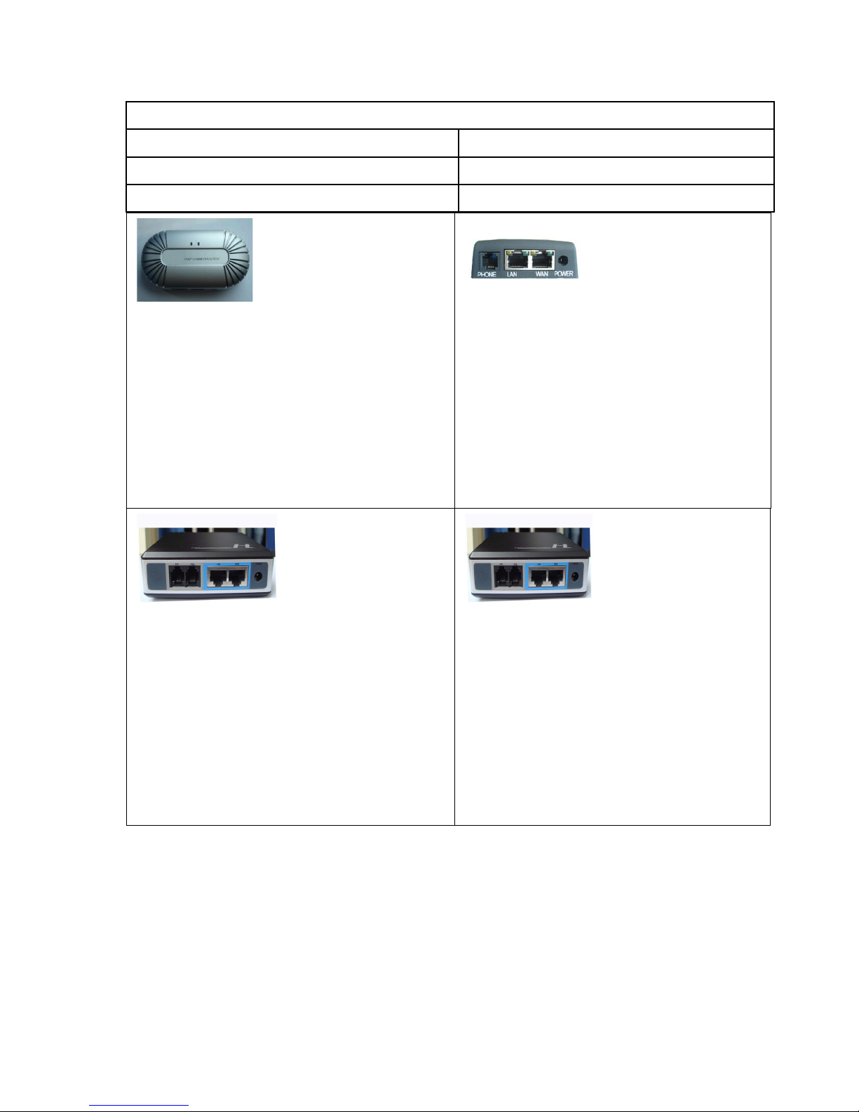
V620 LED explicate
As shown from the above figure ,there are five
indicator light in V620.
1、The first one on the right indicates whether the
gateway has registered to the SIP server. (The
red light flashes if it doesn't register, it doesn't
flash on the contrary. )
2、The second and the forth on the right indicate
whether the LAN\WAN interface of the gateway
has been connected.(They are connected if the
lights are bright.)
3、The third and the fifth show whether there're
data pass throught the interfaces.
V610 LED explicate
As shown from the above figure ,there are five
indicator light in V610.
1、The first one on the right indicates whether the
gateway has registered to the SIP server. (The red
light flashes if it doesn't register, it doesn't flash on
the contrary. )
2、The second and the forth on the right indicate
whether the LAN\WAN interface of the gateway
has been connected.(They are connected if the
lights are bright.)
3、The third and the fifth show whether there're data
pass throught the interfaces.
V610 LED explicate
V610 has 4 LED and one the facing of a quilt
1、the facing of a quilt one indicates whether the
gateway has registered to the SIP server. (The
red light flashes if it doesn't register, it doesn't
flash on the contrary. )
2 、 The green one indicate whether the
LAN\WAN interface of the gateway
has been connected.( It is connected if the light is
bright.)
3、The left one show whether there're data pass
throught the interfaces.
V600 LED explicate
V600 has 2 LED
1、The left one on the right indicates whether the
gateway has registered to the SIP server. (The red
light flashes if it doesn't register, it doesn't flash on
the contrary. )
2、The right one show whether there're data pass
throught the interfaces.
Page 18

17
Set the IP collocation of ATA by voice hint
i、 DHCP mode
According to the 2.2, enter the menu ‘01’ option by voice hint function,
set to DHCP mode.
ii、Static IP mode
According to the 2.2, enter the menu ‘01’ option by voice hint function,
set to static IP mode, and set the IP address of ATA, subnet mask, and the
IP of gateway in the option of ’02 03 04’.
II、Configuring With Web Browser
ATA series products the inside Web server, it can respond the HTTP
GET or POST request from Web Browser, and it has the inside HTML
page layout, it allow the user setting by the Web Browser of the
Microsoft’s IE and AOL’s Netscape.
The collocation menu of ATA can be visited by WAN or LAN port.
The default gateway IP address of LAN port is:
http://192.168.2.1
Get the IP of WAN port:
Press ‘***’ or press the button of ATA equipment to enter the
voice menu
Press ‘02’ can get the IP in English
Use the WAN port to enter the setting Web page, must change the
option ‘Enable Web Access’ to ‘yes’. Then can enter the Web page
by WAN port.
Page 19
18
The network setting menu of ATA:
Open the IE browser, input WAN IP address, will appear the following
page:
The password must case sensitive, and default is ‘voip’.
Input the correct password in the login page, the Web server of ATA will
appear setting menu.
The following is the definition of the parameter in the setting menu
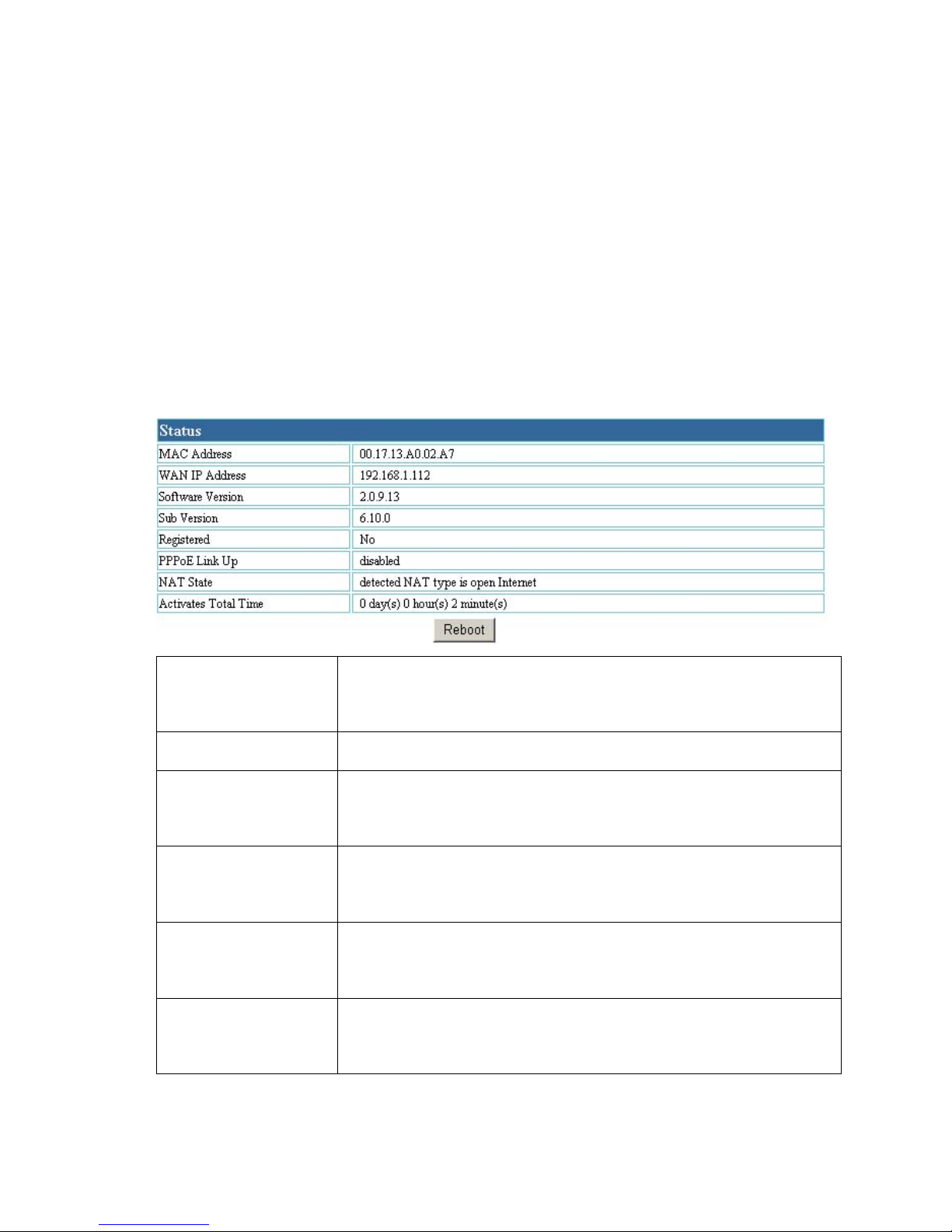
III、status
MAC Address
The device ID, in HEX format. This is a very important
ID for ISP troubleshooting.
WAN IP Address
This field shows WAN port IP address.
Software Version
Program: This is the main software release; its number
is always used for firmware upgrade.
Registered Status
This field indicates whether the device is registered to
the SIP server.
PPPoE Link Up
This field shows whether the PPPoE connection is
enabled or not.
NAT State
This field shows what kind NAT the HT is connected
to via its WAN port. It is based on STUN protocol.
Page 20
19
Activates Total
Time
This field indicates how long the device has been up
since the last reboot.
IV、BASIC OPTIONS
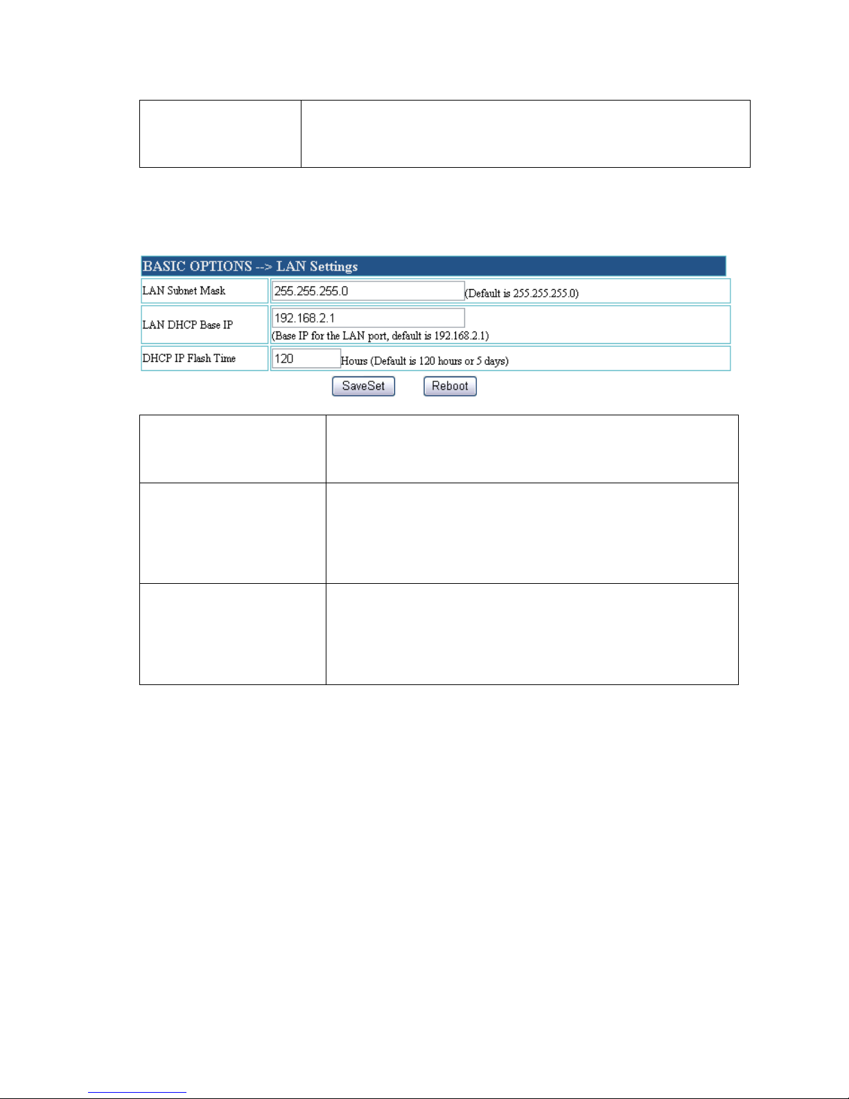
i、LAN Settings
LAN Subnet Mask
Sets the LAN subnet mask. Default value is
255.255.255.0
LAN DHCP Base IP
Base IP for the LAN port which functions as a
Gateway for the subnet. Default value is
192.168.2.1
DHCP IP Flash Time
Value is set in units of hours. Default value is
120hr (5 Days.) The time IP address are assigned
to the LAN clients
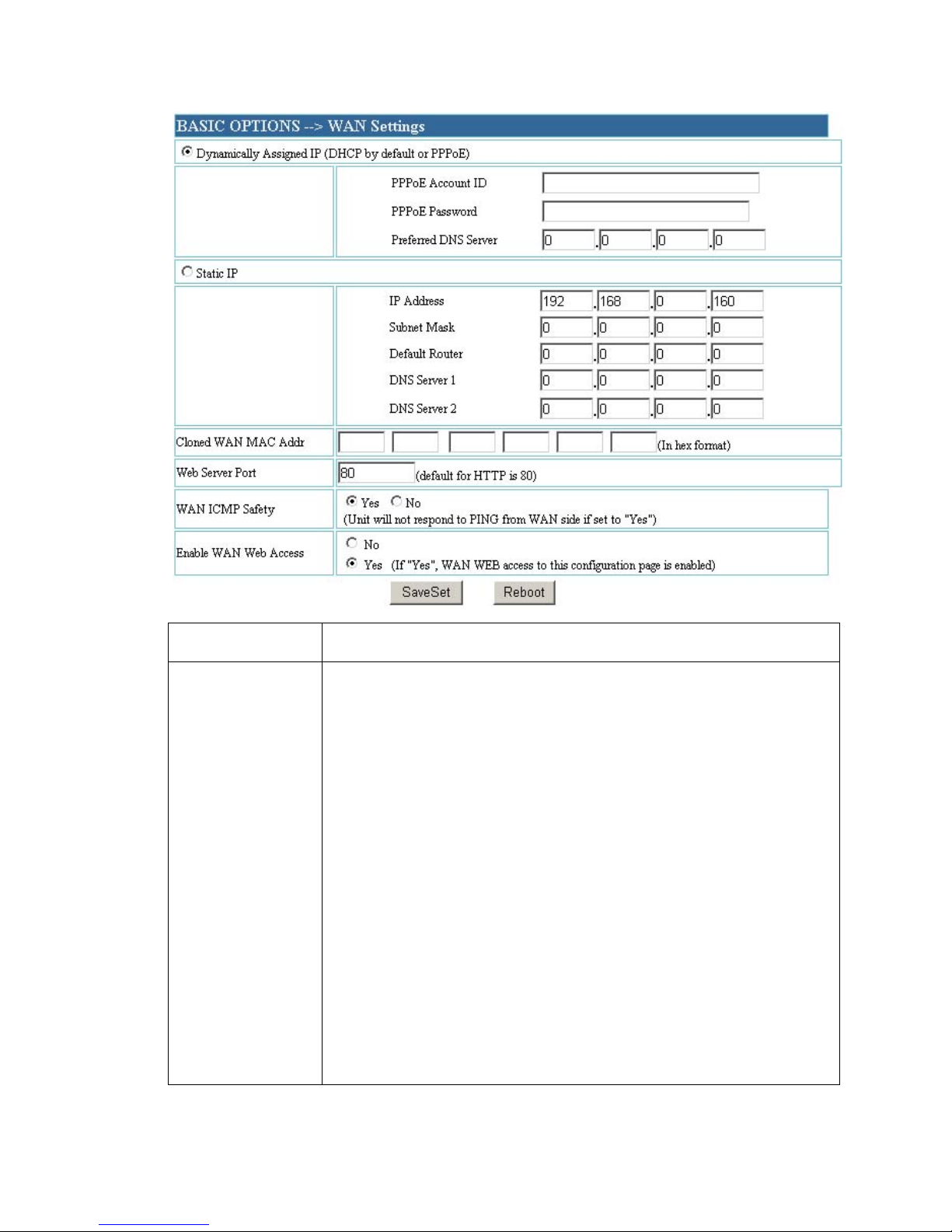
ii、WAN Settings
Page 21
20
PPPoE
The accounts and password of PPPoE.
IP Address
There are 2 modes under which the V600 ata can
operate:
If DHCP mode is enabled then all the field values for
the static ip mode are not used,The V600 will acquire its
IP address from the first DHCP server it discovers from
the connected.
To user the PPPOE feature the PPPOE account
settings need to be set, the V600 will attempt to establish
a PPPOE session if any of the PPPOE field is set
If static IP mode is enabled then IP address 、Subnet
Mask、 Default Router IP address、 DNS Server1、DNS
Page 22
21
Server2 field will need to be configured .These field are
reset to zero by default.
Cloned WAN
MAC Addr
Allow the user to set a specific MAC address. Set in Hex
format
Web server
port
Default for HTTP is 80
WAN ICMP
safety
Unit will not respond to PING from WAN side if set to
“Yes”
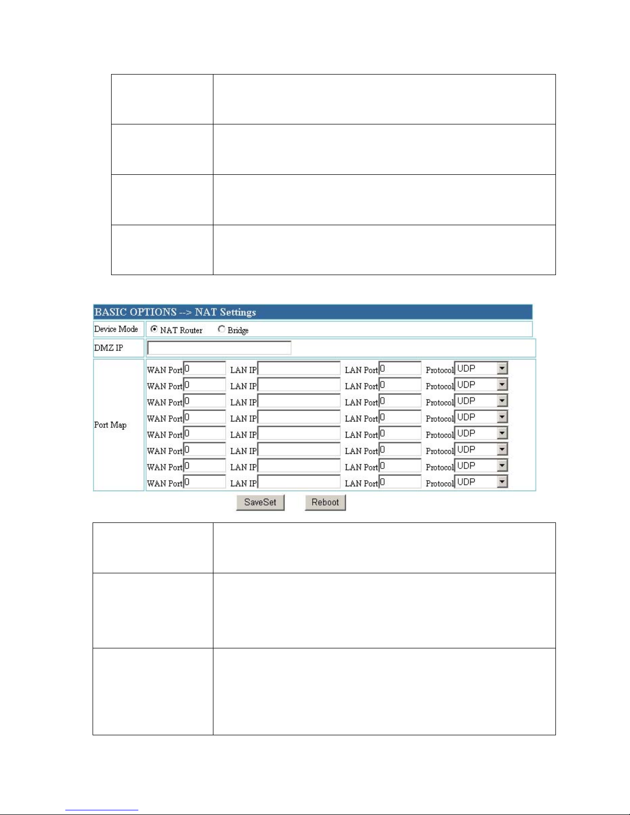
iii、NAT Settings
Device Mode
Default to Router mode ,or set up to bridge mode as the
connection of two Ethernet ports.
DMZ IP
Forward all WAN IP traffic to a specific IP address if no
matching port is used by V600 itself or in the defined
port forwarding
Port Map
Allow the user to forward a matching(TCP/UDP) port to
a specific LAN IP address with a specific(TCP/UDP)
port
Page 23
22
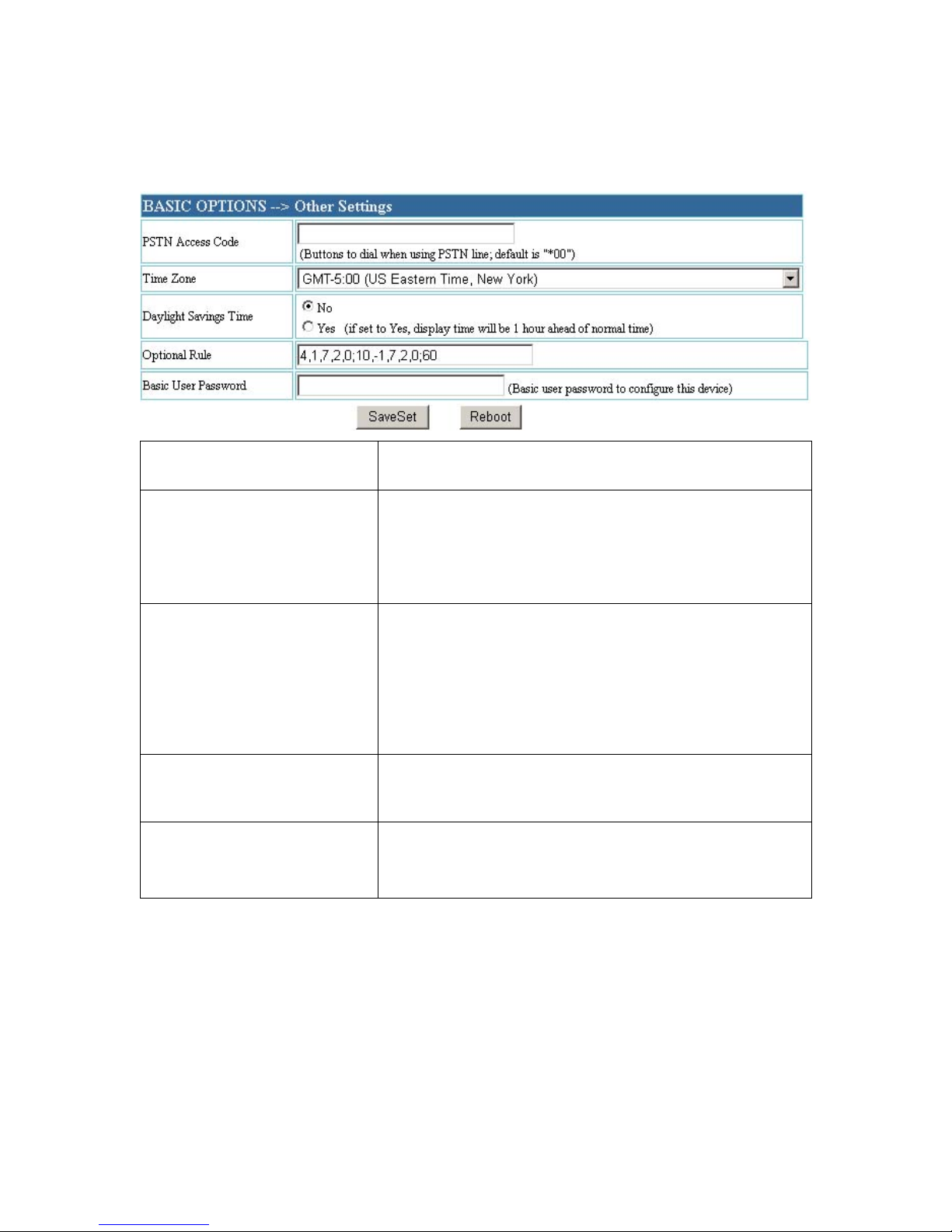
Iv、Other Settings
PSTN Access Code
Key pattern to use PSTN line, default is "*00"
Time Zone
This parameter controls how the displayed
date/time will be adjusted according to the
specified time zone.
Daylight Saving Time
This parameter controls whether the displayed
time will be daylight savings time or not. If set
to Yes, then the displayed time will be 1 hour
ahead of normal time.
Optional Rule
Default is 4.1.7.2.0:10.-1.7.2.0:60
Basic User Password
This contains the password to access the Basic
Options. This field is case sensitive.
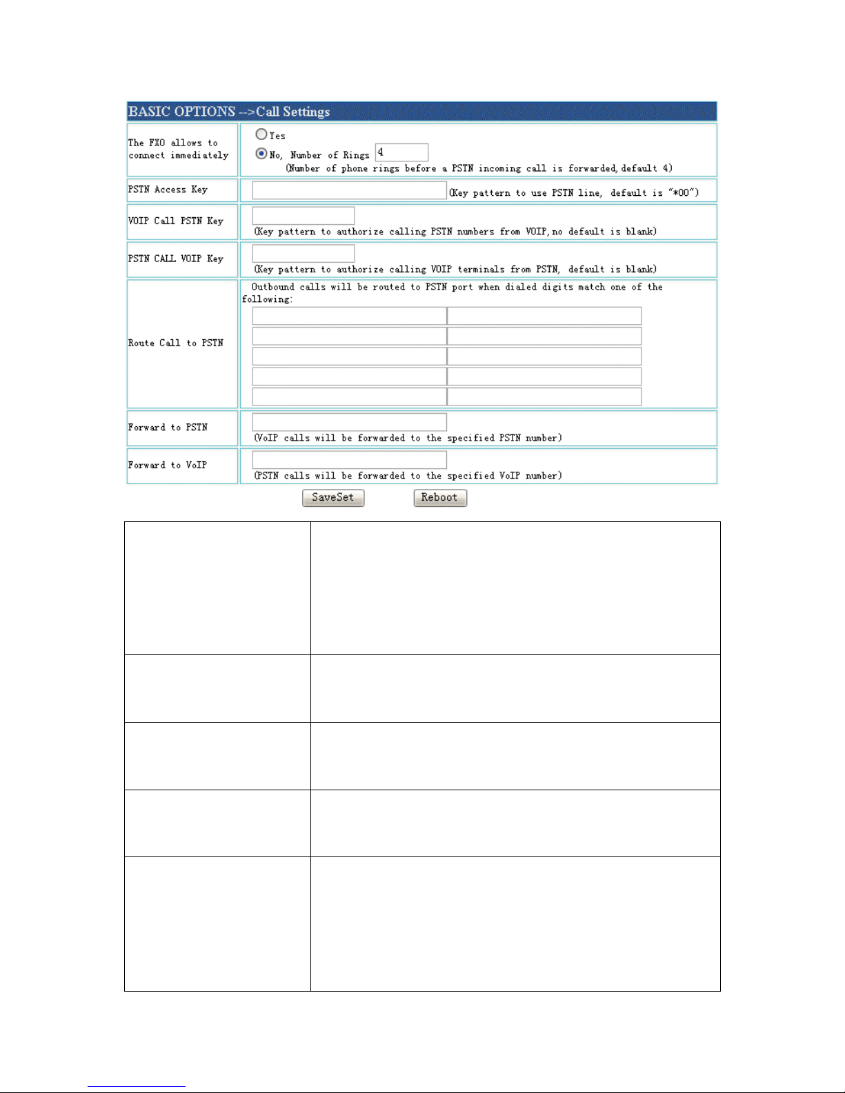
V、Call settings(V610 FXO PORT)
Page 24
23
The FXO allows to
connect immediately
Choosing yes, The phone switch to voip mode in
on time while change now. while choosing no,
Number of rings before PSTN incoming call is
forwarded. Default is 4.
PSTN Access Key
This field allows users to customize their own
code to access the PSTN line. Default is “*00”.
VOIP CALL PSTN
KEY
Key pattem to authorize calling PSTN numbers
from VOIP,no default
PSTN CALL VOIP
KEY
Key pattem to authorize calling VOIP numbers
from PSTN,no default
Route Call to PSTN
If the dialed digits match one of the specified
prefix here, outbound calls will be routed to PSTN
port. This field is especially useful for emergency
calls.
Page 25
24
Forward to PSTN
Calls are unconditionally forwarded to the
specified PSTN phone number once users dial the
FXO port VoIP number.
Forward to VoIP
Calls are unconditionally forwarded to the
specified VoIP phone number once users dial the
FXO port PSTN number.
V、SUPER OPTIONS
i、SIP Settings
Page 26
25
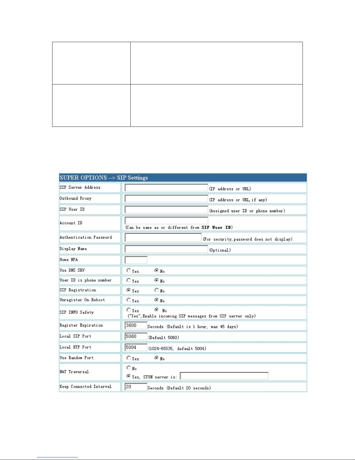
SIP Server Address
SIP Server’s URI or IP address
Outbound Proxy
SIP Outbound Proxy Server’s URI or IP address
SIP User ID
SIP service subscriber’s User ID
Account ID
SIP service subscriber’s Authenticate ID. Can be
identical to or different from SIP User ID
Authentication Password
SIP service subscriber’s account password
Display Name
SIP service subscriber's name which will be used
for Caller ID display
Home NPA
Default is Black.
Use DNS SRV
Default is No. If set to Yes the client will use
Page 27

26
DNS SRV for server lookup
User ID is phone number
If the ATA has an assigned PSTN telephone
number, this field should be set to “Yes”.
Otherwise, set it to “No”. If “Yes” is set, a
“user=phone” parameter will be attached to the
“From” header in SIP request
SIP Registration
This parameter controls whether the ATA needs
to send REGISTER messages to the proxy server.
The default setting is “Yes”
Unregister On Reboot
Default is No. If set to yes, the SIP user will be
unregistered on reboot
SIP INFO Safety
If set to"YES",the device will ignore any SIP
message that does not come from the IP address
(Source IP in the IP header) that it is registered
to.Default setting is "NO"
Register Expiration
This parameter allows the user to specify the time
frequency (in minutes) the ATA refreshes its
registration with the specified registrar. The
default interval is 3V600seconds. The maximum
interval is about 45 days
Local SIP Port
This parameter defines the local SIP port the
ATA will listen and transmit. The default value is
5060(V611FXO port and V620FXS2 port default
5062)
Local RTP Port
This parameter defines the local RTP-RTCP port
pair the ATA will listen and transmit. The default
Page 28

27
value is 5004(V611FXO port and V620FXS2
port default 5008)
Use Random Port
This parameter, when set to Yes, will force
random generation of both the local SIP and RTP
ports. This is usually necessary when multiple
ATA’s are behind the same NAT
NAT Traversal
This parameter defines whether the ATA NAT
traversal mechanism will be activated or not. If
activated (by choosing “Yes”) and a
STUN server is also specified, and then the ATA
will behave according to the STUN client
specification. Under this mode, the embedded
STUN client inside the ATA will attempt to
detect if and what type of
firewall/NAT it is sitting behind through
communication with the specified
STUN server. If the detected NAT is a Full
Cone, Restricted Cone, or a PortRestricted Cone, the ATA will attempt to use its
mapped public IP address and port in all its SIP
and SDP messages. If the NAT Traversal field is
set to “Yes” with no specified STUN server, the
ATA will periodically (every 20 seconds or so)
send a blank UDP packet (with no payload data)
to the SIP server to keep the “hole” on the NAT
open
Keep Connected Interval
This parameter specifies how often the ATA
sends a blank UDP packet to the SIP server in
order to keep the “hole” on the NAT open
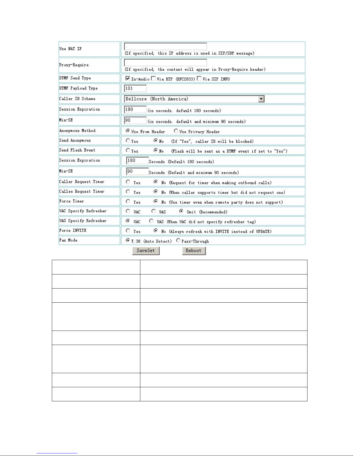
Use NAT IP
NAT IP address used in SIP/SDP message.
Default is blank
Proxy-Require
SIP Extension to notify SIP server that the unit is
behind the NAT/Firewall
DTMF Send Type
This parameter controls how DTMF events are
transmitted. There are 3 ways: in audio which
Page 29

28
means DTMF is combined in audio signal (not
very reliable with low-bit-rate codec), via RTP
(RFC2833), or via SIP INFO
DTMF Payload Type
This parameter sets the payload type for DTMF
using RFC2833
Caller ID Scheme
Bellcore (North America)
ETSI-FSK (France, Germany, Norway, Taiwan,
UK-CCA)
ETSI-DTMF (Finland, Sweden
Denmark-DTMF
CID-Canada
DTMF-Sweden
DTMF-Brazil
Send Anonymous
If this parameter is set to “Yes”, the “From”
header in outgoing INVITE message will be set
to anonymous, essentially blocking the Caller ID
from displaying
Send Flash Event
This parameter allows users to control whether to
send an SIP NOTIFY message indicating the
Flash event, or just to switch to the voice channel
when users press the Flash key
Fax Mode
T.38 mode and pass-through mode
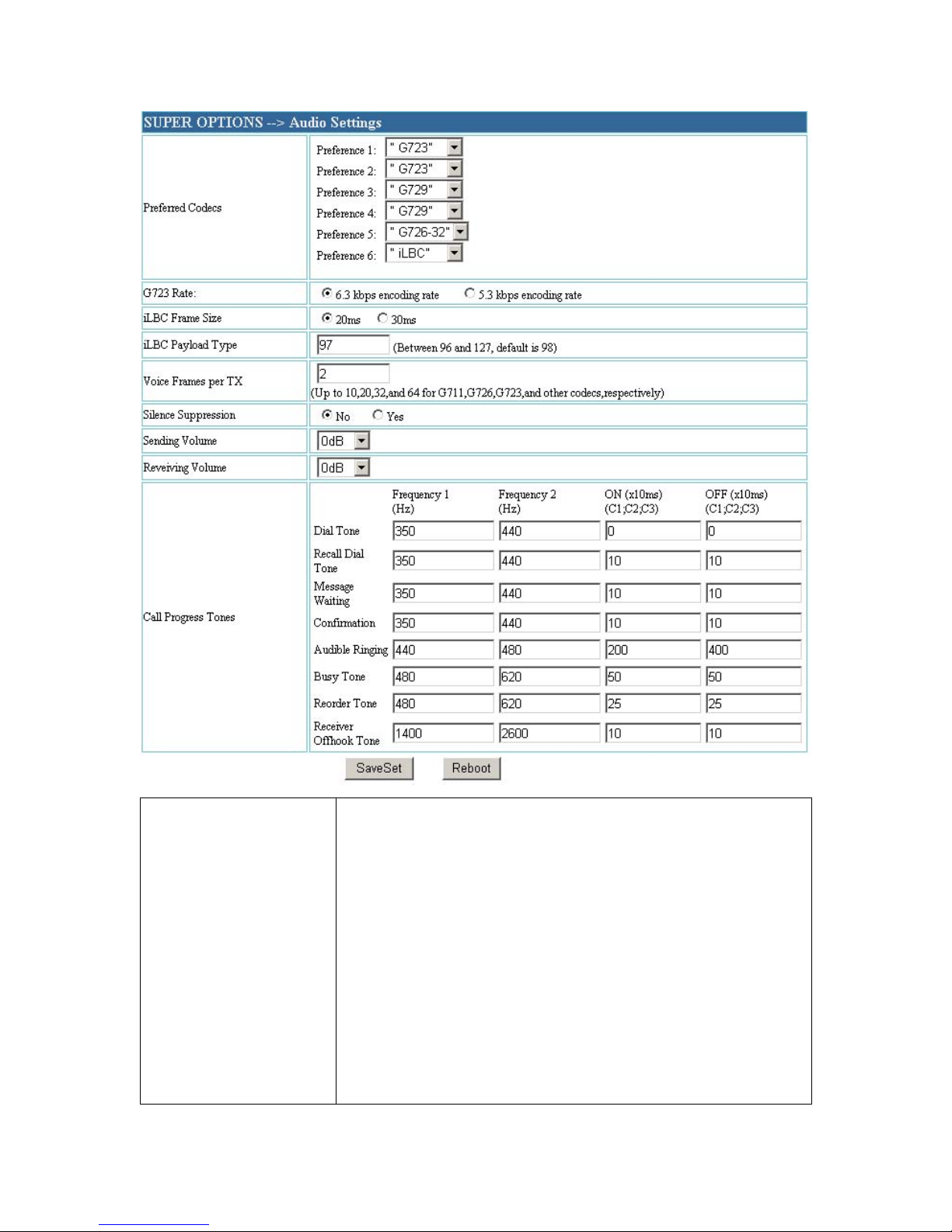
ii、Audio Settings
Page 30
29
Preferred Codecs
The ATA supports up to 7 different Codecs types
including G.711A-/U-law,G.723.1, G.726, G.728,
G.729A/B, iLBC. Depending on the product model,
some of these Codecs may not be provided in
standard release.
Users can configure Codecs in a preference list that
will be included with the same preference order in
SDP message. The first Codecs in this list can be
Page 31

30
entered by choosing the appropriate option in
‘Choice 1’. Similarly, the last Codecs in this list can
be entered by choosing the appropriate option in
‘Choice 7’
G723 Rate
This defines the encoding rate for G723 vocoder. By
default, 6.3kbps rate is chosen
iLBC Frame Size
This sets the iLBC size in 20ms or 30ms
iLBC Payload Type
This defines payload time for iLBC. Default value is
98. The valid range is between 96 and 127
Layer 3 QoS
This field defines the layer 3 QoS parameter which
can be the value used for IP Precedence or Diff-Serv
or MPLS. Default value is 48
Layer 2 QoS(VOIP)
This contains the value used for layer 2 VLAN tag.
Default setting is blank
Layer 2 QoS(PC)
This contains the value used for layer 2 VLAN tag.
Default setting is blank
Silence Suppression
This controls the silence suppression/VAD feature
of G.723 and G729. If set to “Yes”,
when a silence is detected, small quantity of VAD
packets (instead of audio packets)
will be sent during the period of no talking. If set to
“No”, this feature is disabled
Sending or
Reveiving Volume
It can be adjusted the volume in the process
Call progress Tones
It fits to the signal of different countries and areas.
Page 32
31
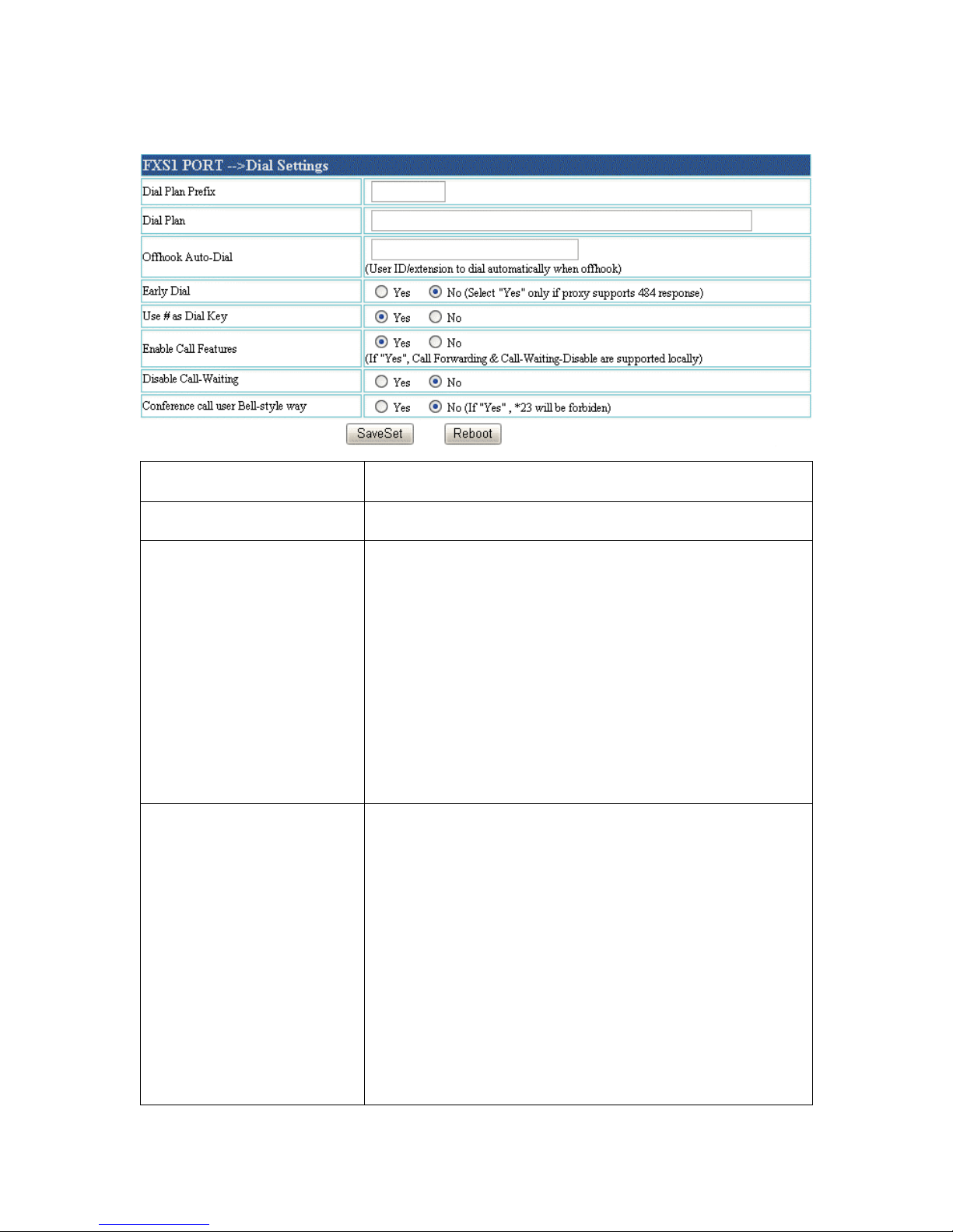
iii、Dial Settings
Dial Prefix
Sets the prefix added to each dialed number
Dial Plan
Sets the dial plan add to dialed number
Offhook Auto-Dial
This parameter allows a user to configure a User
ID or extension number to be automatically
dialed upon offhook. Please note that only the
user CHAPTER of a SIP address needs to be
entered here. The ATA will automatically
append the “@” and the host portion of the
corresponding SIP address
Use # as Dial Key
This parameter allows the user to configure the
“#” key to be used as the “Send”(or “Dial”) key.
Once set to “Yes”, pressing this key will
immediately trigger the sending of dialed string
collected so far. In this case, this key is
essentially equivalent to the “(Re)Dial” key. If
set to “No”, this # key will then be included as
CHAPTER of the dial string to be sent out
Page 33
32
Enable Call Feature
Default is No. If set to Yes, Call Forwarding &
Do-Not-Disturb are supported locally
Disable Call-Waiting
Default is No
Use Bell-style 3-way
Conference
If "Yes",# will be disabled
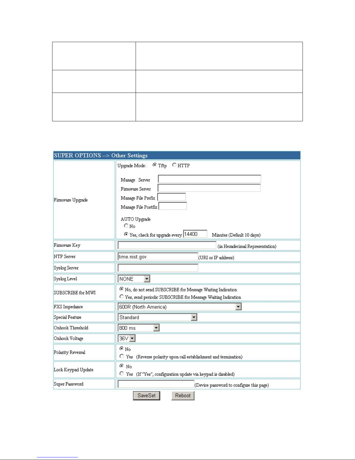
iv、 Other Settings
Page 34

33
Firmware Upgrade
This configures IP address of TFTP server. For
upgrading software, ATA can set a TFTP server
of updating code, use LAN or WAN IP address,
and ATA can work in static IP or DHCP mode.
Suggestion: TFTP server must WAN IP address
or in the same LAN with the ATA
NTP server
The parameter defines URL or IP address of NTP
server, ATA show the current date and time
Syslog Server
The IP address or URL of system log server.This
feature is especially useful for ITSP(Internet
Telephone Service Provider)
Syslog level
Select the ATA to report the log level.Default is
NONE.The level is one of
DEBUG ,INFO,WARNING or ERROR.Syslog
message are sent based on the following events:
1. Product model/Version on boot up(INFO
level)
2. Sent or received SIP message(DEBUG level)
3. SLIC chip exception(Warning and error
levels)
4. Memory ecxception(ERROR level)
Subscribe for MWI
Default is NO. When set to Yes a SUBSCRIBE
for Message Waiting Indication will be sent
periodically
FXS Impedance
Selects the impedance of the analog telephone
connected to the Phone port
Page 35
34
Special Feature
Default is Standard.Choose the selcetion to meet
some special requirements from Soft Switch
vendors like Nortel,Broadsoft,etc
Onhook Threshold
The amount of time the hookflash is pressed that
will cause the device to onhook.Default is 800ms
Onhook Voltage
Select the onhook voltage to suit different area or
PBX
Polarity Reversal
Select polarity reversal to calculate the cost for
some system, default is No
Lock Keypad Update
If this parameter is set to "Yes",the configuration
update via keypad is disabled
Super Password
Administrator password.Only administrator can
configure the "Advanced Settings"page.This field
is case sensitive and the maximum password
length is 25 characters.
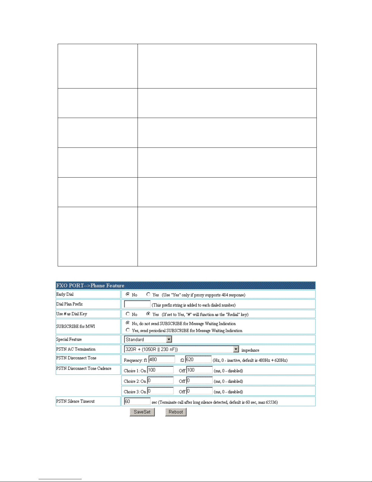
V FXO PORTPhone Feature
Page 36

35
Early Dial
Default is No. Use only if proxy supports 484
response
Dial Plan Prefix
Sets the prefix added to each dialed number
Use # as Dial Key
This parameter allows the user to configure the
“#” key to be used as the “Send”(or “Dial”) key.
Once set to “Yes”, pressing this key will
immediately trigger the sending of dialed string
collected so far. In this case, this key is
essentially equivalent to the “(Re)Dial” key. If
set to “No”, this # key will then be included as
CHAPTER of the dial string to be sent out
Offhook Auto-Dial
This parameter allows a user to configure a User
ID or extension number to be automatically
dialed upon offhook. Please note that only the
user CHAPTER of a SIP address needs to be
entered here. The ATA will automatically
append the “@” and the host portion of the
corresponding SIP address
SUBSCRIBE for MWI
If set “Yes”, send periodic SUBSCRIBE for
Message Waiting Indication
PSTN Silence Timeout
Terminate call after long silence detected, default
is 60 sec, max 65536
PSTN Disconnect Tone
This configuration should be configured by the
VOIP service provider.Some country use single
frequency tone to signal PSTN
disconnection,some country use double
Page 37
36
frequency tone.
PSTN Disconnect Tone
Cadence
This setting can be configured to suit the
telephone company's standard in different
country.
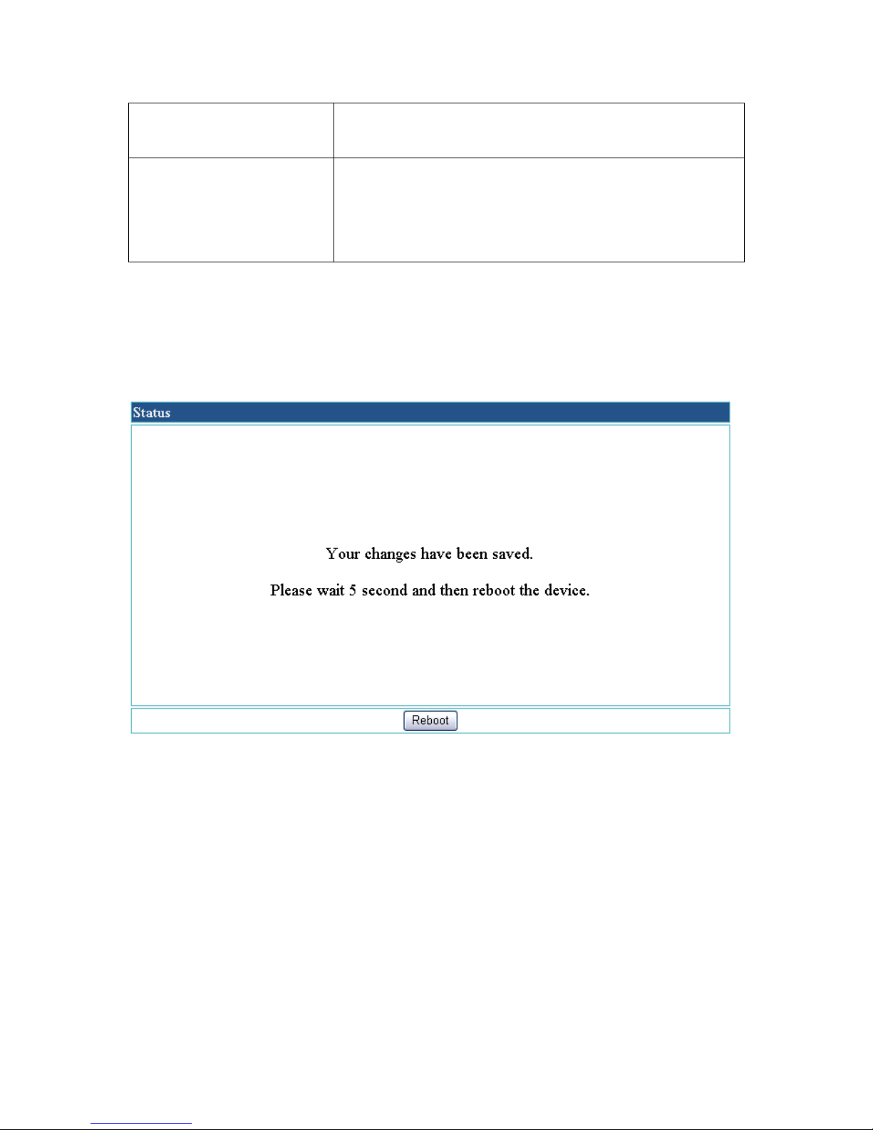
Once a change is made, the user should press the “Update” button in the
Configuration Menu. The ATA will then display the following screen to
confirm that the changes have been saved
Users are recommended to power cycle the ATA after seeing the above
message
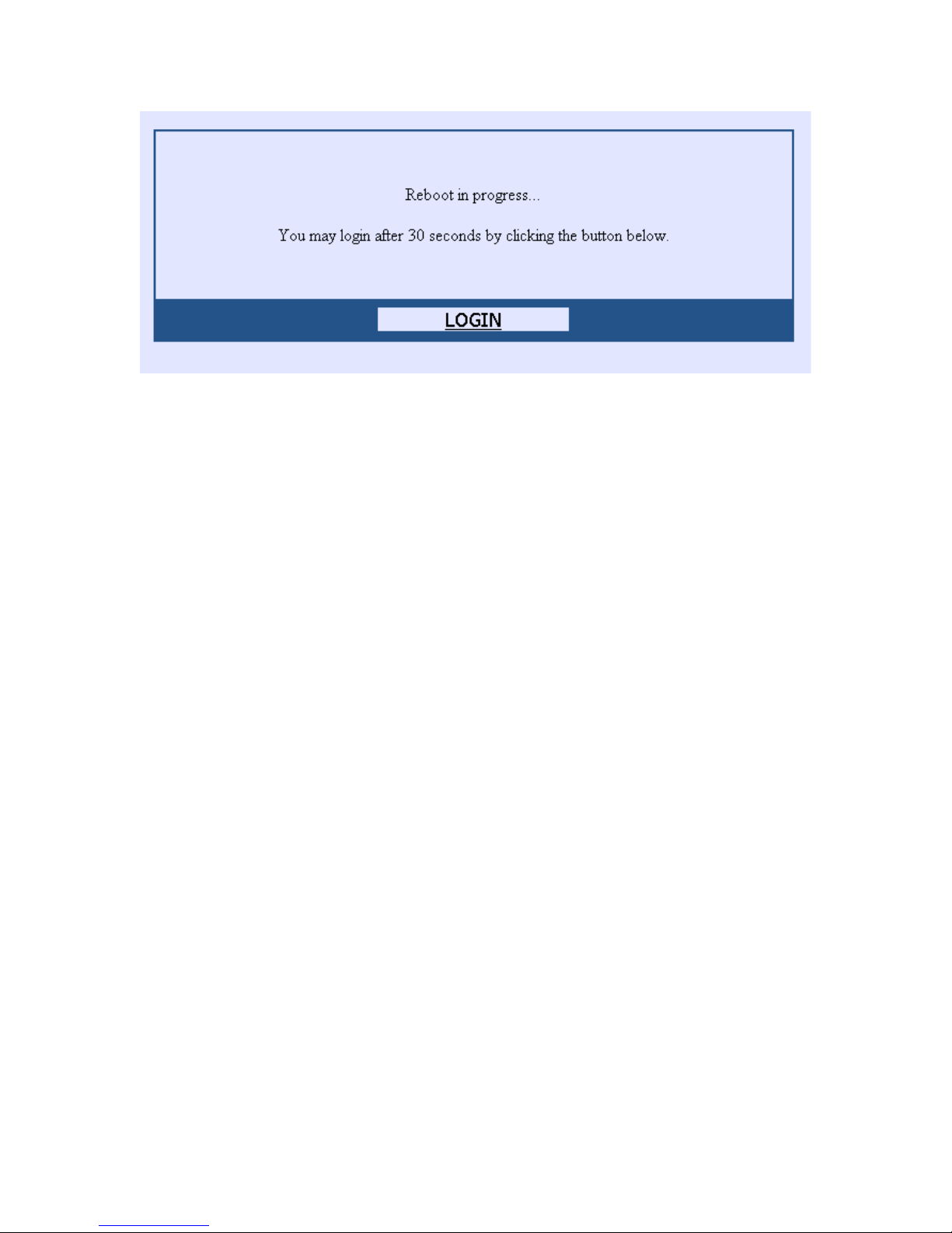
The administrator of the ATA can remotely reboot the ATA by pressing the
“Reboot” button at the bottom of the configuration menu. Once done, the
following screen will be displayed to indicate that rebooting is underway
Page 38
37
At this point, the user can relogin to the ATA after waiting for about 30
seconds.
CHAPTER 5 Restore Factory Default Setting
Warning: Restore the Factory Default Setting will delete all
configuration information of the device.
Step one: Find the MAC Address of the device. The MAC address of the
device is located on the bottom of the device. It is a 12 digits number.
Step two: Encode the MAC address. The encode rule is:
“2” is the first letter on the button “2” so its encoding is “2”.
“A” is the second letter on button “2” so its encoding is “22”.
“B” is the third letter on button “2” and its encoding is “222”.
“C” is the fourth letter on button “2” and its encoding is
“2222”.
For example, for MAC address 000b8200e395, the user should encode it
as “0002228200333395”.
Step three: Access the voice menu, then dial “99” and get the voice prompt
“RESET”
Step four: Dial in the encoded MAC address. Once the correct encoded
Page 39
38
MAC address is dialed in, the device will reboot automatically and restore
the factory default setting.
Chapter 6 Upgrade
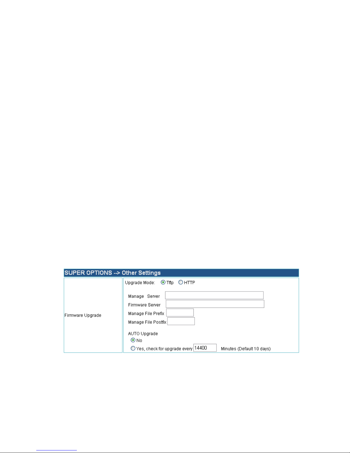
The 6xx Series Products support two types of update modes: TFTP and
HTTP
Attention : Please clear the SIP Server address and Account before
remote update;
Disconnect to the internet before local update (optional).
The whole process will cost at least 10 minutes, in the period the power
can never be cut off and any manipulation to the phone is not allowed.
to avoid physical break to the gateway , do not cut off the power
immediately after the reboot.
一、 TFTP UPDATE
V6xx Series products can work both in DHCP and Static IP mode. The
TFTP server is supposed to have a public IP address or the TFTP server
and the V6xx products are in the same LAN.
1 LOCAL UPDATE
1) Set up a TFTP server, put the update software package to the root
directory of this server, open the TFTP server.
2) Open the configuration page of the gateway, find the place as the
following picture:
1. Please specify the Update Mode as :TFTP
2. Fill the Firmware Server item with the Local TFTP server.
3. Click SaveSet then reboot.
二、 HTTP UPDATE
V6xx Series products can work both in DHCP and Static IP mode. The
HTTP server is supposed to have a public IP address or the TFTP server
Page 40
39
and the V6xx products are in the same LAN.
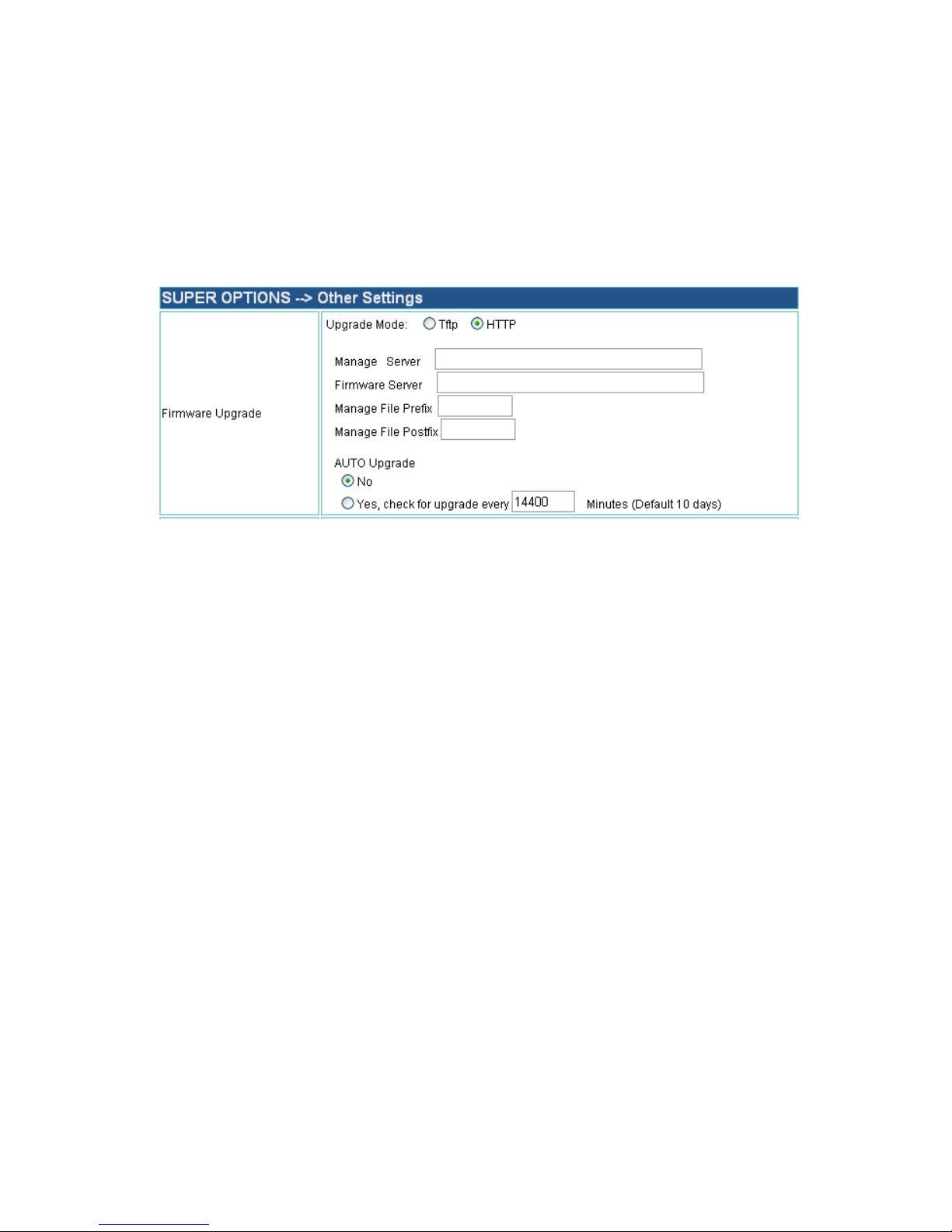
1 LOCAL UPDATE
1) Set up a HTTP server, put the update software package to the root
directory of this server, open the HTTP server.
2) Open the configuration page of the gateway, find the place as the
following picture:
1. Please specify the Update Mode as :HTTP
2. Fill the Firmware Server item with the Local HTTP server.
3. Click SaveSet then reboot.
HFS—HTTP Server 2.0a is commended for remote software.
2 REMOTE UPDATE
Please contract us to get a TFTP Server address if you need remote
update.
CHAPTER 7 Ordinary Quality Checking
Bobbling the ATA, no exceptional noise。
Use the standard electrical source, connect it without any other
equipment,If the electrical source is OK, you will see: the red LED light
will on, after a sound 'pa', it will shine slowly.
CHAPTER 8 FAQ
、I can open ‘Status’ and ‘Basic setting’, but cannot open the ‘Super
options’, why?
Because when you input the password, you make a mistake. There are
two password, one is super user password (default is ‘admin’), it can
open all the pages. The other one is user password (default is ‘123’), it
cannot open the ‘Super options’ page.
Page 41

40
、There is no voice hint after pressing ‘***’ on the phone, why?
First, checking the parameter on the configuration pages, whether there
is a parameter has been set as ‘*’ or ‘**’ or ‘***’, if have, please change
to others’
Then, ‘Offhook Auto-Dail’ parameter must be empty.
、The ATA got an IP, but I cannot open the configuration pages, why?
First, make sure that your computer and the ATA connect the NET.
Then, make sure that your computer and the ATA are in the same
segment.
Last, make sure that the phone connected to the ATA is onhook.
、I can visit Internet when I make a VOIP call, why?
It’s always caused by the bandwidth. Please change the Voice Code, so
that it cost less bandwidth.
、When I press Speaker or make a call, there is some cacophony, why?
First, make sure that all the equipments are OK, then, debug the
impedance and onhook voltage of FXS port.
、The ATA cannot get IP automatically, why?
First, check the way of connecting; make sure it’s no problem,
Then, visit the configuration through LAN port, make sure all the
equipments in the LAN are use DHCP.
、The IP address of the ATA is 0.0.0.0, why?
Main problem: some thing wrong with the connecting, or there is no
DHCP in the LAN.
、Cannot visit the configuration pages through WAN port, why?
First, the option on configuration pages called ‘Enable WAN Web
Access’, when you choose ‘no’, you cannot visit the configuration pages
through WAN port.
Then, checking the connection, make sure it is no problem; click Start
then Run, input ‘ping (WAN IP) –l 65000 –t’ order, it can help you to
check the status of the NET.
、Use PPPOE, the ATA can make a VOIP call, but cannot connect the
Page 42

41
NET, why?
Please set the DNS Server yourself.
、Cannot visit the configuration pages through LAN port, why?
Make sure that all the connecting is OK,
Pull out the connection to the WAN port (if the SIP Account is
invalidation, but the connection to the WAN port is OK, it will make the
ATA power off automatically.
Set the computer as DHCP, then reboot the ATA
Check the default gateway, the default gateway of the computer is the
LAN address of ATA
 Loading...