

Page 1
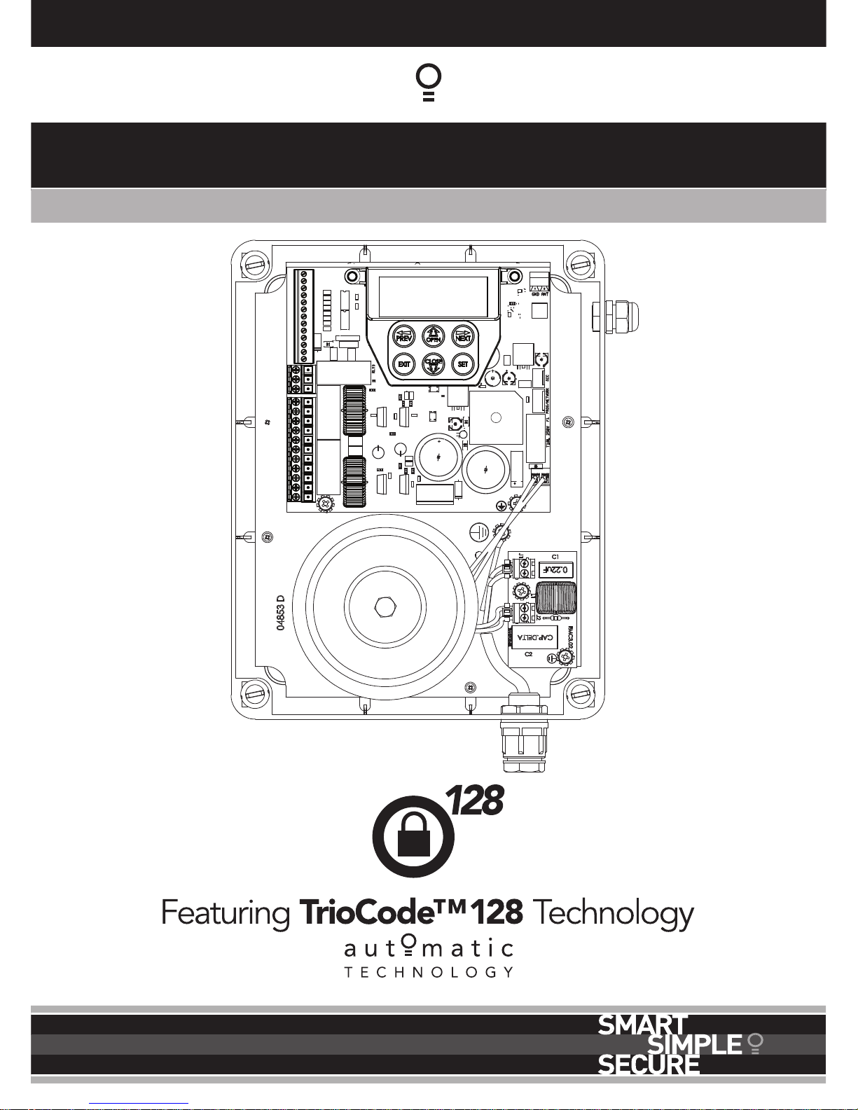
Dual Gate Controller
24 Volt Gate Control System DCB-05V2
Doc # 160020_04
Part # 13314
Released 02/06/15
Page 2

2
DCB-05V2 Gate Controller Owner Installation Instructions
Automatic Technology Australia Pty Ltd to the extent that such may be lawfully excluded hereby expressly disclaims all conditions or warranties, statutory
or otherwise which may be implied by laws as conditions or warranties of purchase of an Automatic Technology Australia Pty Ltd Garage Door Opener.
Automatic Technology Australia Pty Ltd hereby further expressly excludes all or any liability for any injury, damage, cost, expense or claim whatsoever
suffered by any person as a result whether directly or indirectly from failure to install the Automatic Technology Australia Pty Ltd Garage Door Opener in
accordance with these installation instructions.
Dual Gate Controller
24 Volt Gate Control System DCB-05V2
Contents
1. Important Safety Instructions 3
2. Control Board Layout 4
3. Set Up Requirements 5
3.1 Kit Contents 5
3.2 Choosing your Set up 5
4. Installation Requirements 5
4.1 Mounting Control Box 5
4.2 Installing antenna 5
5. Wiring Diagrams - Single Gates 6
5.1 Wiring motors and limit switches 6
5.2 Diodes 1N4004 or equivalent 6
6. Wiring Diagrams - Dual Gates 7
6.1 Wiring motors and limit switches 7
6.2 Diodes 1N4004 or equivalent 7
6.3 Dual NeoSlider Kit 8
7. Programming the DCB-05V2 9
7.1 Common Programs 9
7.2 Powering up the DCB-05V2 9
8. Setting Limits 10
8.1 Setting Travel Limits 10
8.2 Adjusting Close Limit(s) 10
8.3 Adjusting Open Limit(s) 10
8.4 Automatic Profiling 10
8.5 Code A Transmitter For Limit Setting 11
8.6 Setting Limits Via Transmitter 11
9. Safety Obstruction Force Test 12
9.1 Testing Close Cycle (Single Swing Gates) 12
9.2 Testing Open Cycle (Single Swing Gates) 12
9.3 Force Pressure For Close Cycle. 12
9.4 Force Pressure For Open Cycle. 12
9.5 Reprofiling Travel 12
10. Coding Transmitter 13
10.1 Coding Transmitter Button 13
10.2 Selecting Function Of The Button 13
10.3 Returning To Main Screen 13
11. Remotely Coding Transmitters 13
11.1 Selecting The Function To Be Coded 13
12. Setting Pedestrian Position 14
12.1 Setting the Pedestrian Position 14
12.2 Checking Pedestrian Position 14
12.3 Error Displays 14
11.2 Activate Remote Code Set Mode 14
13. Auto-Close Mode 15
13.1 Setting Up Standard Auto-Close 15
13.2 Safety Beam Triggered Auto Close 15
13.3 Pedestrian Auto-Close 15
13.4 Auto-Close After Obstruction: 15
14. Accessories Installation 16
14.1 Fitting Solenoid Or Magnetic Locks 16
14.2 Fitting Courtesy Lights 16
15. Battery Replacement 16
16. Battery Disposal 17
17. Specifications 17
18. Troubleshooting 18
19. Appendix 19
A - Console Menu Structure 19
B - Viewing and Editing Parameters 22
C - Control Board Adjustments 23
D- Diagnostic Tools 24
E - Memory Tools 26
F- Transmitter Editing 26
G- Transmitter Managment 27
H- AMP Travel (2 Wires Setup) 28
I - Time Travel 2 Wire Setup 30
20. Warranty and Exclusion of Liability 31
Page 3
Owner Installation Instructions DCB-05V2 Gate Controller 3
1. Important Safety Instructions
The safety alert symbols below indicate a personal safety or property
damage instruction exists. READ THESE INSTRUCTIONS CAREFULLY.
This DCB-05V2 Gate Opener is designed and tested to offer safe service provided it is
installed and operated in strict accordance with the following safety rules. Failure to
comply with the following instructions may result in death, serious personal injury or
property damage.
WARNING! • The gate may operate unexpectedly, therefore do not allow anything to stay in the
path of the gate.
• Do not disengage the gate opener to manual operation with children/persons or any
objects including motor vehicles within the gateway.
• Make sure the gate is fully open before driving into or out of the driveway.
• When using auto close mode, a Photo Electric beam must be fitted correctly and
tested for operation at regular intervals. Extreme caution is recommended when
using auto close mode. All safety rules must be followed.
ELECTROCUTION! • Do not immerse in or spray the DCB-05V2 with water .
• Disconnect the power cord from mains power before making any repairs or
removing covers. Only experienced service personnel should remove covers from
the gate opener.
• If the power supply cord is damaged, it must be replaced by an Automatic Technology
service agent or suitably qualified person.
• Connect the gate opener to a properly earthed general purpose 240V mains power
outlet installed by a qualified electrical contractor.
CAUTION:
Entrapment from
operating gate
• DO NOT operate the gate opener unless the gate is in full view and free from objects
such as cars and children/people. Make sure that the gate has finished moving before
entering or leaving the driveway.
• Do not allow children to play with gate controls or transmitters.
• In order for the DCB-05V2 to sense an object obstructing the gateway, some force
must be exerted on the object. As a result the object, gate and/or person may suffer
damage or injury.
• Regularly check to make sure that the Safety Obstruction Force is working correctly,
and is tested and set as per Section 12 of this manual. Failure to follow these
instructions could result in serious personal injury and/or property damage. This
test must be repeated at regular intervals and the necessary adjustments made as
required.
• If using a key switch, keypad or any device that can operate the gate opener, make sure
it is in a location where the gateway is visible, but out of the reach of children at a
height of at least 1.5m.
• For ADDITIONAL SAFETY protection we STRONGLY recommend the fitting of a
Photo Electric (Safety) Beam. In most countries Safety Beams are mandatory on all
gates fitted with automatic openers.
Installation
• Ensure the gate(s) is in good working order. Faulty gates must be repaired by a qualified
technician prior to DCB-05V2 installation.
Security • Make sure that the gate is fully closed before leaving the driveway.
Entanglement in
or laceration from
moving gate
• Keep hands and loose clothing clear of gate at all times
• Keep clear of gate during operation as severe lacerations can occur on sharp edges of
gate.
Page 4
4
DCB-05V2 Gate Controller Owner Installation Instructions
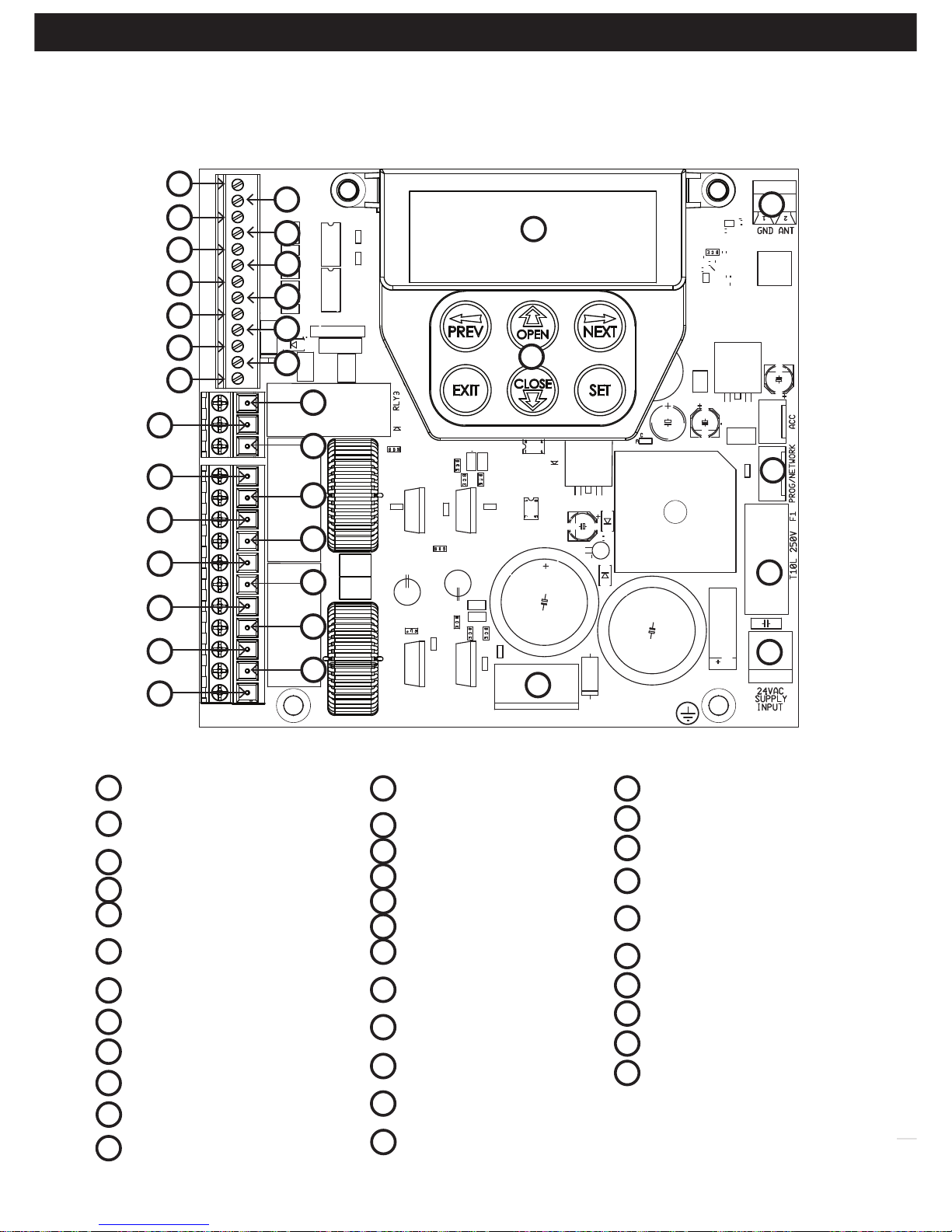
2. Control Board Layout
SB2 (Safety Beam (2),
two, three wire or wireless)
SB1 (Safety Beam(1),
two, three wire or wireless)
0V
Aux control input
OPN Programmable
N/O or N/C input terminal
STP Programmable
N/O or N/C input terminal
CLS N/O input terminal
OSC N/O input terminal
SWP N/O input terminal
PED N/O input terminal
0V
V+
28
29
13
34
33
30
31
01
02
03
04
05
06
07
08
09
10
11
12
Fig 2.1
32
OUT 2 (optional relay
module coil drive)
OUT 1 N/C relay contact
OUT 1 COM relay contact
OUT 1 N/O relay contact
MOTOR 2 terminal 1
MOTOR 2 terminal 2
MOTOR 2 close limit switch
input terminal
MOTOR 2 open limit switch
input terminal
COM terminal for Terminals
19,20,22 &23.
MOTOR 1 close limit switch
input terminal
MOTOR 1 open limit switch
input terminal
MOTOR 1 terminal 1
13
MOTOR 1 terminal 2
V PWR for accessories
0V
Standby battery /
solar charger connector
24VAC power input
(from transformer)
10 amp fuse
Programmer / Network Input
Console keypad
Console display (LCD)
Antenna connector
14
15
16
17
18
19
20
21
22
23
24
25
26
27
28
29
30
31
32
33
34
01
02
03
04
05
06
07
08
09
10
11
12
27
15
17
19
21
23
25
14
16
18
20
22
24
26
Page 5
Owner Installation Instructions DCB-05V2 Gate Controller 5
3. Set Up Requirements
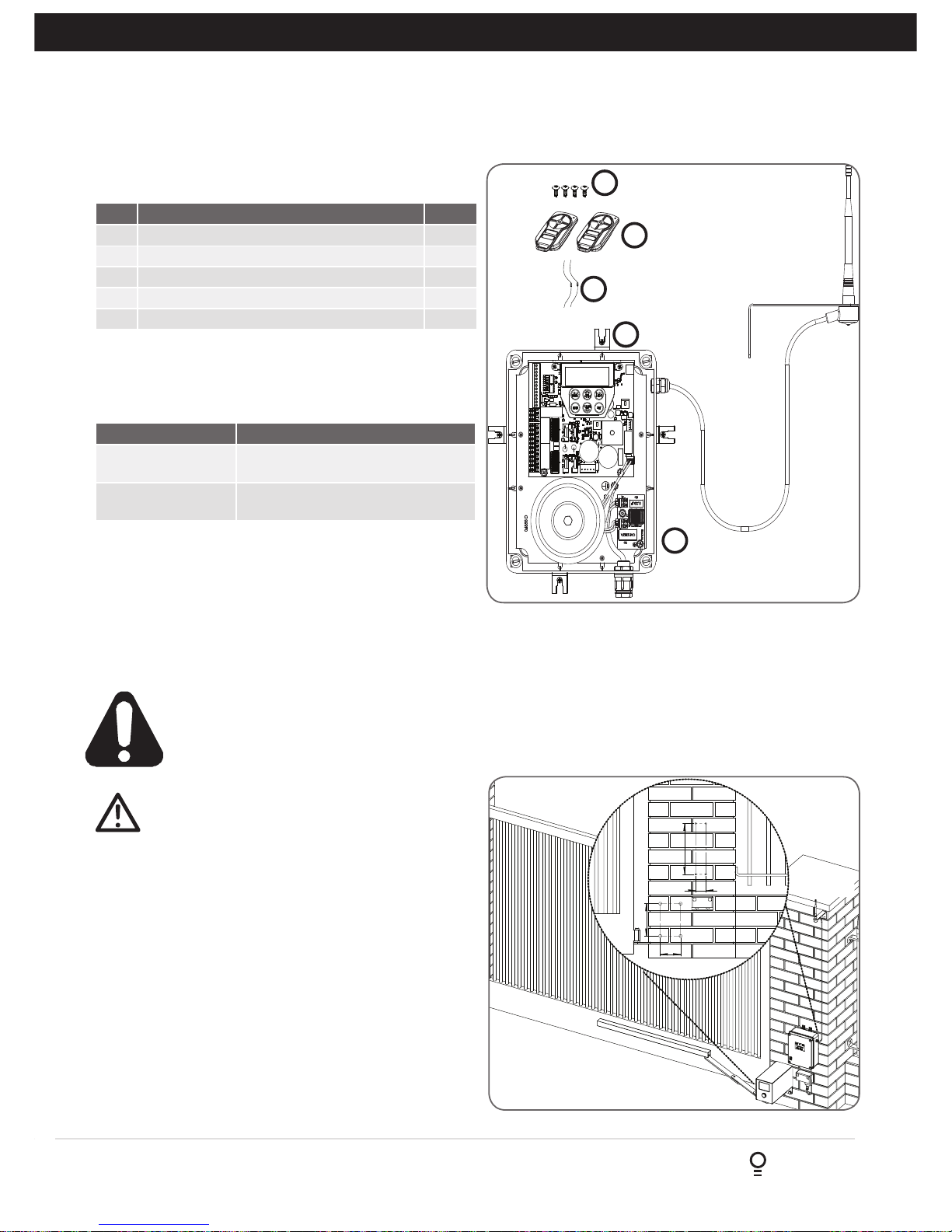
Fig 3.1
3.1 Kit Contents
3.2 Choosing your Set up
The DCB-05V2 can be set up in various ways and therefore
may require additional items. Common Set ups are as follows;
Item Description Qty
1 GATE CONTROL SYSTEM DCB05 1
2 MOUNTING LUGS FOR GEWISS BOX 4
3 SCREW “P” M3.5 X 13 4
4 TRIO-CODE 4B PTX-5V2 TRANSMITTER 2
5 RESISTOR 5K6 2
1
2
3
4
5
Set Up Items Required
Automated Set Up Drive Unit, control system and
transmitter
Automated Set Up
with Safety Beams
Drive Unit, control system, transmitter
and safety beams (optional extra)
4. Installation Requirements
IMPORTANT SAFETY INSTRUCTIONS FOR INSTALLATION
Warning: Incorrect installation can lead to severe injury.
Follow ALL installation instructions.
CAUTION: do not use any cables which carry
green/yellow wires as this signifies earth, and do
not comply with electrical authority regulations.
4.1 Mounting Control Box
a. The control box should be mounted near the drive unit
using four (4) 6mm screws.
b. Drill holes as per (Fig. 4.1). When locating the control
box, allow ample space around the unit for easy access
and wiring connections.
c. Remove cover from control box.
d. Dual Gates Only- Determine which leaf you would like to
open first and close last. This gate leaf must be connected
to Motor 1 (M1) terminals on the control board.
e. Connect drive unit(s) to control board. For detailed
electrical connection see Section 5.
4.2 Installing antenna
Mount the antenna at or above the height of the gate
or fence (whichever is higher) for optimal reception.
Do not cut the coaxial cable.
110
175
55
275
Fig 4.1
Figure shows minimum
sideroom kit
Antenna
Page 6
6
DCB-05V2 Gate Controller Owner Installation Instructions
5. Wiring Diagrams - Single Gates
5.1 Wiring motors and limit switches
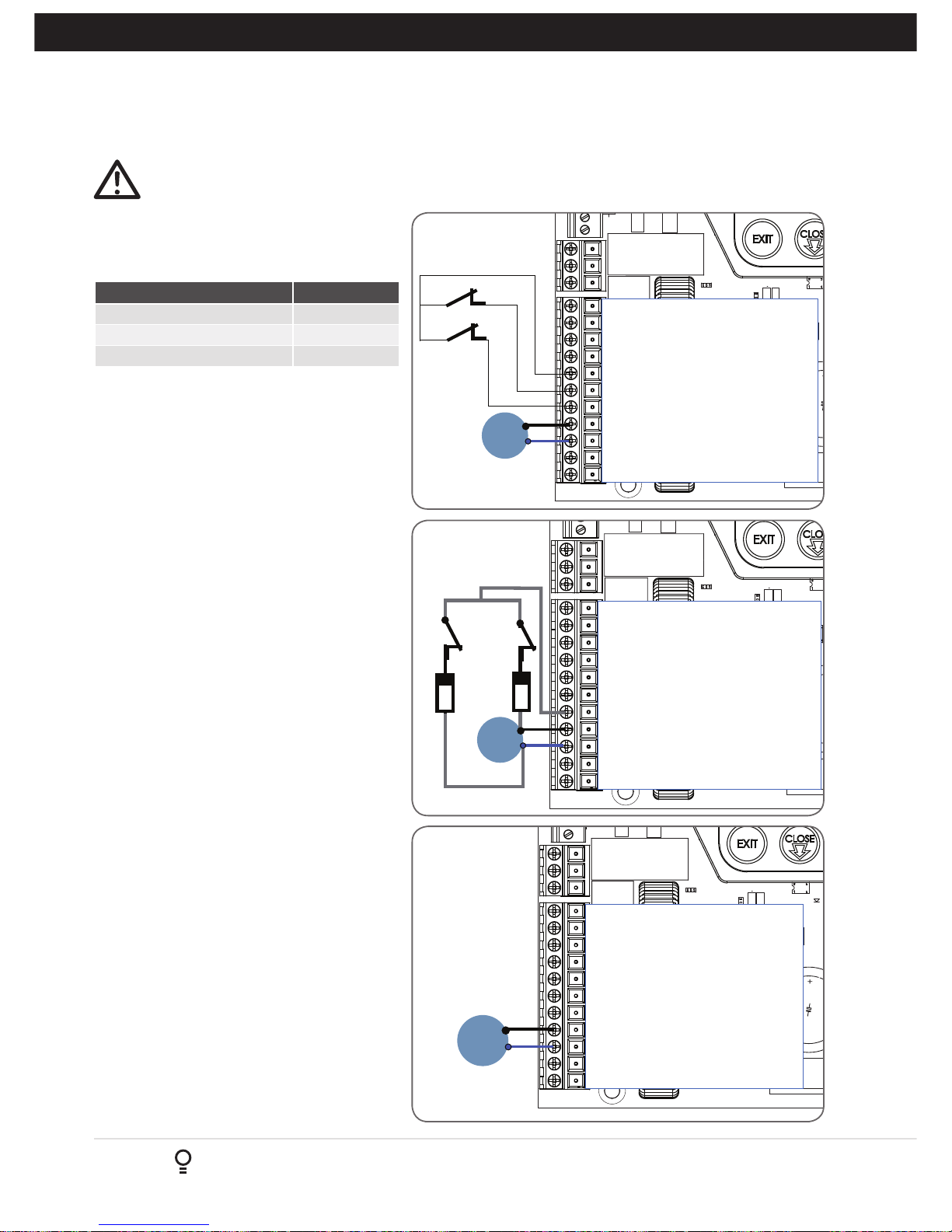
DCB-05V2 can be connected to the single gate
drive units in one of several ways.
Wiring Figure #
5 Wire, Single Gate 5.1
3 Wire Single Gate 5.2
2 Wire Single Gate 5.3
The diagrams (Fig. 5.1 to Fig. 5.3) show the
various wiring methods used for different drive
unit types. Select the appropriate method for your
drive unit.
NOTE:“non-motor current carrying limit-switch”
type drive units can be connected using the
standard 5 wire connections or a special 3 wire
method that uses a single limit switch sense wire
and two diodes.
5.2 Diodes 1N4004 or equivalent
(not included)
The most common function of a diode is to allow
an electric current to pass in one direction and
to block the current in the opposite direction.
The diode is a unidirectional electronic
component. It must be used as shown in
Fig. 5.2 to work properly.
NOTE: The motor travel direction can be
reversed by swapping the motor connections. An
opportunity to confirm the correct motor polarity
is provided during the limit setup procedure.
MI
Close
MOTOR 2 TERMINAL 1
MOTOR 2 TERMINAL 2
MOTOR 2 CLOSE LIMIT SWITCH INPUT
MOTOR 2 OPEN LIMIT SWITCH INPUT
COMMON FOR MOTOR 1 & 2 LIMIT SWITCHES
MOTOR 1 CLOSE LIMIT SWITCH INPUT
MOTOR 1 OPEN LIMIT SWITCH INPUT
MOTOR 1 TERMINAL 1
MOTOR 1 TERMINAL 2
V PWR FOR ACCESSORIES
OV
Open
MOTOR 1
MOTOR 2 TERMINAL 1
MOTOR 2 TERMINAL 2
MOTOR 2 CLOSE LIMIT SWITCH INPUT
MOTOR 2 OPEN LIMIT SWITCH INPUT
COMMON FOR MOTOR 1 & 2 LIMIT SWITCHES
MOTOR 1 CLOSE LIMIT SWITCH INPUT
MOTOR 1 OPEN LIMIT SWITCH INPUT
MOTOR 1 TERMINAL 1
MOTOR 1 TERMINAL 2
V PWR FOR ACCESSORIES
OV
MI
MOTOR 1
1N4004 diode
open
close
1N4004 diode
MOTOR 2 TERMINAL 1
MOTOR 2 TERMINAL 2
MOTOR 2 CLOSE LIMIT SWITCH INPUT
MOTOR 2 OPEN LIMIT SWITCH INPUT
COMMON FOR MOTOR 1 & 2 LIMIT SWITCHES
MOTOR 1 CLOSE LIMIT SWITCH INPUT
MOTOR 1 OPEN LIMIT SWITCH INPUT
MOTOR 1 TERMINAL 1
MOTOR 1 TERMINAL 2
V PWR FOR ACCESSORIES
OV
MI
MOTOR 1
Fig 5.1
Fig 5.2
Fig 5.3
CAUTION: Cables which have a green/yellow coloured insulation are for earthing purposes only.
Never use these cables for any other purpose.
Page 7
Owner Installation Instructions DCB-05V2 Gate Controller 7
6. Wiring Diagrams - Dual Gates
MOTOR 2 TERMINAL 1
MOTOR 2 TERMINAL 2
MOTOR 2 CLOSE LIMIT SWITCH INPUT
MOTOR 2 OPEN LIMIT SWITCH INPUT
COMMON FOR MOTOR 1 & 2 LIMIT SWITCHES
MOTOR 1 CLOSE LIMIT SWITCH INPUT
MOTOR 1 OPEN LIMIT SWITCH INPUT
MOTOR 1 TERMINAL 1
MOTOR 1 TERMINAL 2
V PWR FOR ACCESSORIES
OV
MI
M2
MOTOR 2
MOTOR 1
open
close
open
close
MOTOR 2 TERMINAL 1
MOTOR 2 TERMINAL 2
MOTOR 2 CLOSE LIMIT SWITCH INPUT
MOTOR 2 OPEN LIMIT SWITCH INPUT
COMMON FOR MOTOR 1 & 2 LIMIT SWITCHES
MOTOR 1 CLOSE LIMIT SWITCH INPUT
MOTOR 1 OPEN LIMIT SWITCH INPUT
MOTOR 1 TERMINAL 1
MOTOR 1 TERMINAL 2
V PWR FOR ACCESSORIES
OV
M1
M2
MOTOR 1
1N4004 diode
open
close
1N4004 diode
1N4004 diode
open
close
1N4004 diode
MOTOR 2
MOTOR 2 TERMINAL 1
MOTOR 2 TERMINAL 2
MOTOR 2 CLOSE LIMIT SWITCH INPUT
MOTOR 2 OPEN LIMIT SWITCH INPUT
COMMON FOR MOTOR 1 & 2 LIMIT SWITCHES
MOTOR 1 CLOSE LIMIT SWITCH INPUT
MOTOR 1 OPEN LIMIT SWITCH INPUT
MOTOR 1 TERMINAL 1
MOTOR 1 TERMINAL 2
V PWR FOR ACCESSORIES
OV
MI
MOTOR 1
M2
MOTOR 2
Fig 6.1
Fig 6.2
Fig 6.3
6.1 Wiring motors and limit switches
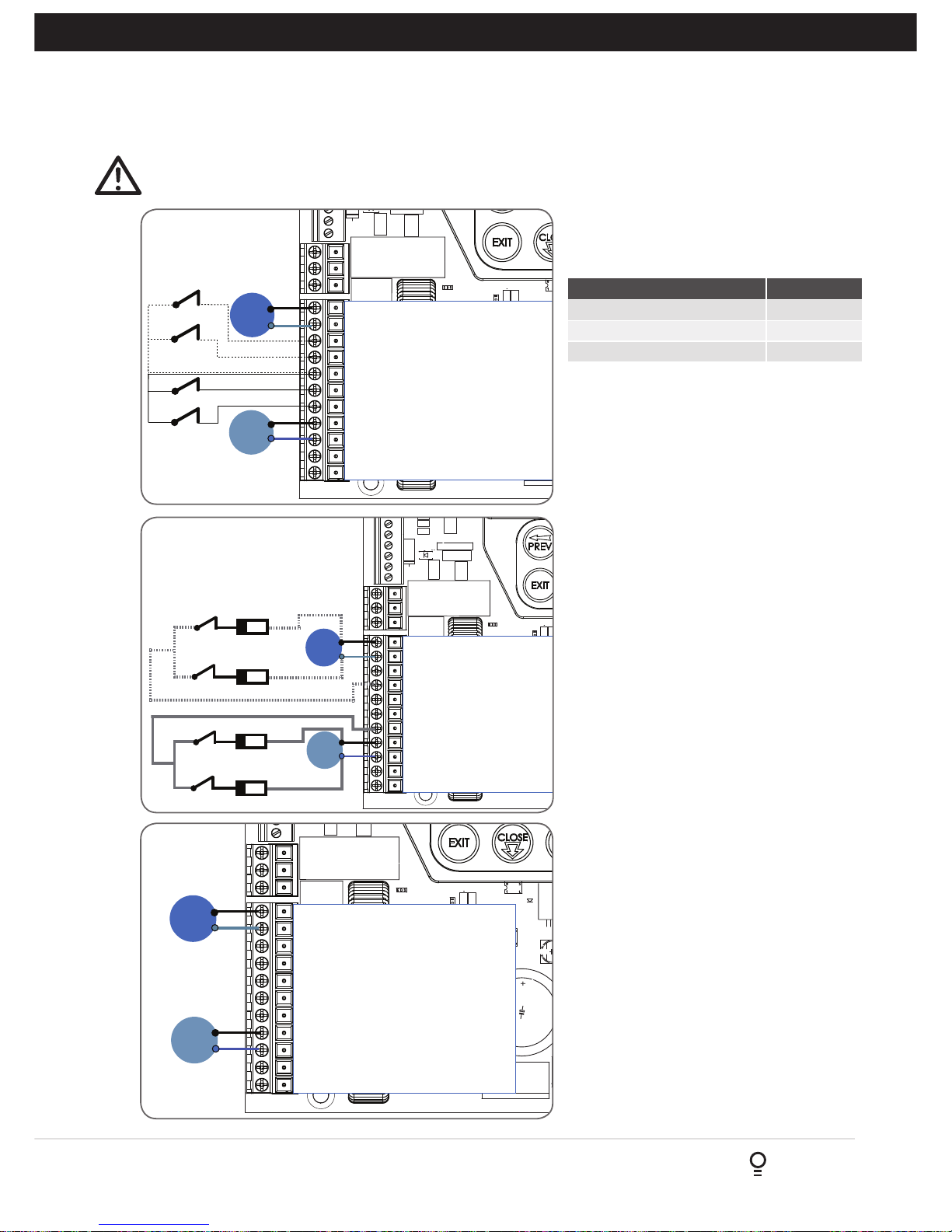
DCB-05V2 can be connected to the dual gate
drive units in one of several ways.
Wiring Figure #
5 Wire Dual Gate 6.1
3 Wire Dual Gate 6.2
2 Wire Dual Gate 6.3
The diagrams (Fig. 6.1 to Fig. 6.3) show the
various wiring methods used for different drive
unit types. Select the appropriate method for
your drive unit.
NOTE:“non-motor current carrying limitswitch” type drive units can be connected using
the standard 5 wire connections or a special
3 wire method that uses a single limit switch
sense wire and four diodes.
6.2 Diodes 1N4004 or equivalent
(not included)
The most common function of a diode is to allow
an electric current to pass in one direction and
to block the current in the opposite direction.
The diode is a unidirectional electronic
component. It must be used as shown in
Fig. 5.2 to work properly.
NOTE: the drive unit connected to the MOTOR
1 terminals will open first and will be used for
pedestrian access.
NOTE: The motor travel direction can be
reversed by swapping the motor connections. An
opportunity to confirm the correct motor polarity
is provided during the limit setup procedure.
CAUTION: Cables which have a green/yellow coloured insulation are for earthing purposes only.
Never use these cables for any other purpose.
Page 8
8
DCB-05V2 Gate Controller Owner Installation Instructions
Limits Motor
C O
Com
1
2
MSI-1.00 Board
Limits Motor
C O
Com
1
2
MSI-1.00 Board
ATA DCB-05V3 (150VA)
MOTOR 2 TERMINAL 1
MOTOR 2 TERMINAL 2
MOTOR 2 CLOSE LIMIT SWITCH INPUT
MOTOR 2 OPEN LIMIT SWITCH INPUT
COMMON FOR MOTOR 1 & 2 LIMIT SWITCHES
MOTOR 1 CLOSE LIMIT SWITCH INPUT
MOTOR 1 OPEN LIMIT SWITCH INPUT
MOTOR 1 TERMINAL 1
MOTOR 1 TERMINAL 2
V PWR FOR ACCESSORIES
OV
Red
Black
White
Blue
Orange
Black
White
Orange
Red
Blue
Fig 6.4
6.3 Dual NeoSlider Kit
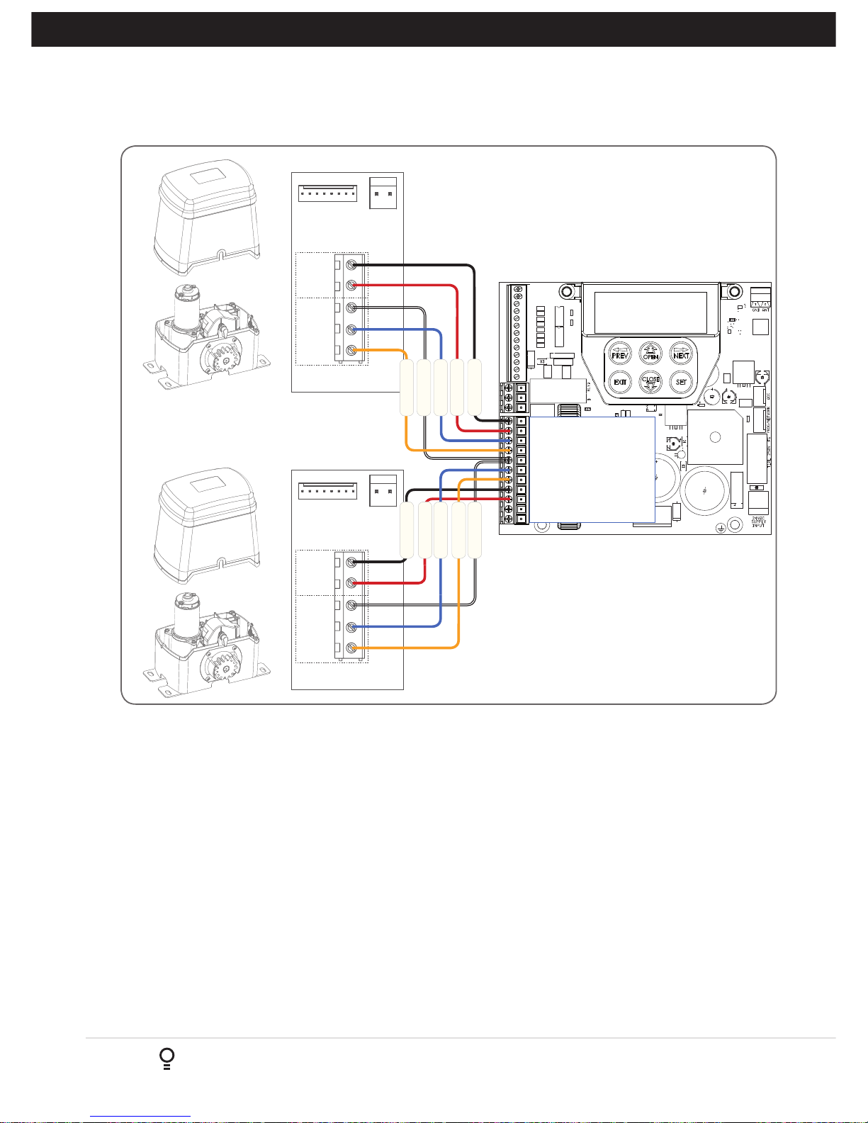
This section illustrates how to wire two NeoSliderTM slave openers into a DCB-05V2. (Fig. 6.4)
NOTE:
When setting limits, if both openers are travelling in different directions (i.e one is opening and the other is
closing), then do the following:
a. Switch over the motor wires (marked red and black in Fig 6.4) on the incorrectly behaving openers MSI board.
b. Restart the limit set up process.
6.
Wiring Diagrams - Dual NeoSlider Kit
Page 9
Owner Installation Instructions DCB-05V2 Gate Controller 9
7. Programming the DCB-05V2
7.1 Common Programs
The two most common programs are;
Program Menu’s required Function Section
Automated Set Up Menu 10.1 Setting the Limits 8.1
Safety Obstruction Force 9.1 and 9.2
Menu 1 Coding the Transmitter 10.1
Automated Set Up with
Safety Beams
Menu 10.1 Setting the Limits 8.1
Safety Obstruction Force 9.1 and 9.2
Menu 1 Coding the Transmitter 10.1
Menu 3 Auto Close Times 13.2, 13.3 and 13.4
NOTE: Fitting Safety Beams enables the Auto-Close feature to become active.
CAUTION: Before plugging the gate control system
in, check the power cord for damage and ensure it
cannot become entangled in any moving parts
7.2 Powering up the DCB-05V2
a. After checking the initial wiring, apply power to the DCB-05V2.
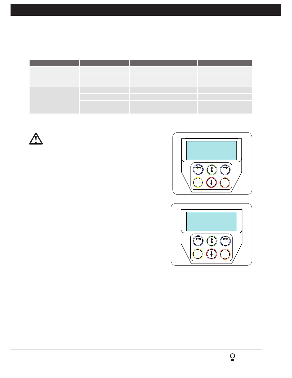
The controller will go through a startup sequence displaying
the STARTUP SCREEN which indicates the controller type
and firmware version (Fig. 7.2). After a short delay the MAIN
SCREEN will be displayed.
b. If this is the first time the DCB-05V2 has been used, the MAIN
SCREEN should indicate that the limits are not set (Fig. 7.3).
If the display shows that some input is active then rectify
the situation before proceeding. If a default setting is to be
changed it should be done now before setting the travel limits.
A.T.A GCS24
FIRMWARE X.XX
PREV NEXT
EXIT
SET
Limits Not Set!
Press <> To Acess MENU
PREV NEXT
EXIT
SET
Start up screen
Main screen
Fig 7.2
Fig 7.3
Fig 7.1
Page 10
10
DCB-05V2 Gate Controller Owner Installation Instructions
8. Setting Limits
DCB-05V2 can be used with drive units that use different methods to
stop at the end of their travel.
The types supported are:
Wiring Type
3 or 5 Wire setup Limit switch - Open and close limit switches indicate
to DCB-05V2 when the travel limit is reached
2 Wire setup
(See Appendix
H & I for
instructions)
AMP trip limits - Travel limits are detected by
and an increase in motor current as mechanical
stops are reached.
Timing - The motor is driven for a preset
time. When the travel limit is reached a clutch
incorporated into the drive unit allows the
motor to keep turning for the remaining preset
running time.
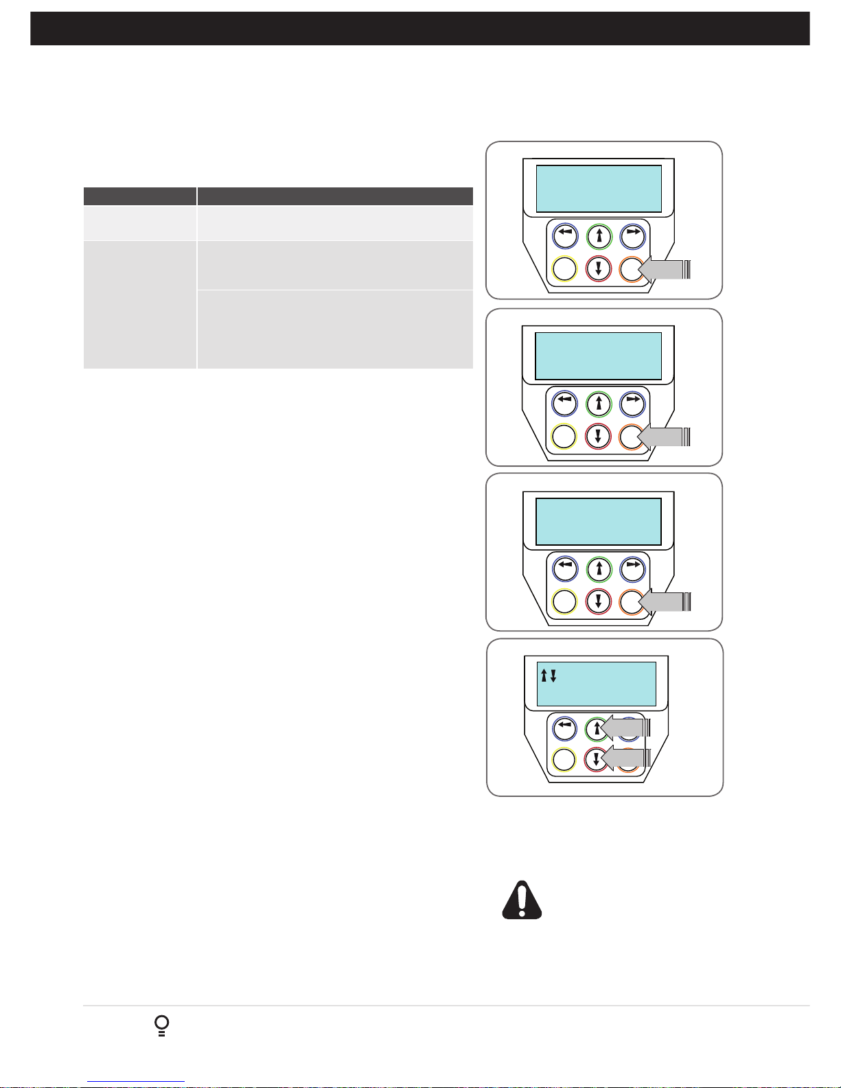
8.1 Setting Travel Limits
Navigating To “Limit/AMP Travel Menu”
a. Scroll to the right using next button to access MENU 10
b. Press SET to display MENU 10.1.
c. Press SET again to start the limit setting procedure (Fig. 8.1).
d. DCB-05V2 will prompt you to confirm that the motor wiring is complete
(Fig. 8.2) and that the gate(s) are at fully open position and engaged.
e. Press SET to confirm.
f. DCB-05V2 will now automatically detect the type of drive unit used by
the number of wires used. If the correct number of wires is displayed
then press SET to continue otherwise press EXIT and check the wiring.
NOTE: For 2 Wire Setup refer to Appendix H for “AMP Travel”
g. DCB-05V2 will now automatically detect if one or two motor are
connected. If the correct number is displayed then press SET to
confirm. Otherwise press EXIT and check the wiring (Fig. 8.3).
8.2 Adjusting Close Limit(s)
a. DCB-05V2 will prompt one at a time for the motor(s) to be driven to
the desired close limit and for the limit switches to be adjusted so
that the motor stops at the desired position.
b. Drive the motor using the UP and DOWN arrows on the console
keypad (Fig. 8.4).
c. After making adjustments to the limit switch positions always
re-approach the limit at full speed by driving the motor open a short
distance and then driving it close again.
d. When the close limit is adjusted to the desired position press SET to
continue.
NOTE: If the motor drives in the wrong direction (UP closes gate /
DOWN opens gate) the motor wires need to be swapped
8.3 Adjusting Open Limit(s)
a. DCB-05 will now prompt for the motor(s) to be driven to the desired
open limit and for the limit switches to be adjusted so that the motor
stops at the desired position.
b. Drive the motor using the UP and DOWN arrows on the console
keypad.
c. After making adjustments to the limit switch positions always
re-approach the limit at full speed by driving the motor close a short
distance and then driving it open again.
d. When the open limit has been adjusted to the desired position, press
SET.
Fig 8.1
Fig 8.2
Fig 8.3
MENU 10.1
Limit/AMP Travel
PREV NEXT
EXIT
SET
PRESS
Selecting Limit/AMP Travel Setup
Motor Wiring
PREV NEXT
EXIT
SET
Completed ?
PRESS
Confirming Wiring is Completed
M1&2 Detected
PREV NEXT
EXIT
SET
Press Set If OK
PRESS
Confirming Detected Motor Wiring
PREV NEXT
EXIT
SET
Close Limit,Set
M1,2 & Adjust
PRESS
PRESS
Adjusting The CLOSE LIMIT
Fig 8.4
8.4 Automatic Profiling
After a brief pause DCB-05V2 will automatically
close and open gate several times and learn the
gate(s) load and travel characteristics.
WARNING: The gate(s) will
automatically close and open. Ensure
that no persons or objects are in the
gates path.
When the setup is complete the MAIN SCREEN
will be displayed with the gate shown to be OPEN.
The Gate can now be used.
Page 11

Owner Installation Instructions DCB-05V2 Gate Controller 11
8. Setting Limits: Via Transmitter
Button 1
(Inch Open)
Button 4
(Inch Close)
Button 2
(Set)
The DCB-05V2 has the alternate ability to set travel limits using a
transmitter, allowing free movement around the gate to better assess
the desired limit positions. In order to use a transmitter, it must first
have at least one of its buttons coded to the gate controller. The
function assigned to the transmitter’s buttons is of no concern here
as the buttons are temporally assigned to OPEN, CLOSE and SET
(Fig. 8.5).
8.5 Code A Transmitter For Limit Setting
Navigating to “code transmitter” menu
a. Press NEXT to navigate to Menu 1.
b. Press SET to enter the code set procedure (Fig. 8.6).
Storing Transmitter Code
a. Controller will prompt to press one of the transmitter’s Button.
b. Press the transmitter button you wish to use to operate the gate
opener (e.g. button 1) .
c. Press the same transmitter button again as prompted by display.
d. Press the SET button to store the transmitter.
Navigating To “Set Gate Travel Menu”
a. Press PREV to navigate to Menu 10.
b. Press SET to display MENU 10.1.
c. Press SET two times to enter the limit setting procedure. Follow
LCD prompts.
8.6 Setting Limits Via Transmitter
a. Press and hold Button 4 on the transmitter to close the gate
i. If the gate is closed too far, press Button 1 to “inch” the gate
towards open.
ii. When happy with the close limit position, press Button 2 to store
this in the memory.
b. Press Button 1 to open the gate.
i. If the gate is opened too far, press Button 4 to “inch” the gate
towards close
WARNING: The gate will automatically close and open
once next step is performed. Ensure that no persons or
objects are in the gates path.
c. When happy with the open limit position, press Button 2 on the
transmitter to store into memory.
d. The gate will now automatically close and open to calculate the safety
obstruction settings.
Fig 8.5
Fig 8.6
MENU 1
PREV NEXT
EXIT
SET
Code Transmitter
PRESS
IMPORTANT NOTE: Only
TrioCode
TM
128 Technology Transmitters
are compatible with this product.
Page 12
12
DCB-05V2 Gate Controller Owner Installation Instructions
9. Safety Obstruction Force Test
WARNING! Take care when testing or adjusting the
Safety Obstruction Force. Excessive force may cause
SERIOUS PERSONAL INJURY and/or PROPERTY
DAMAGE.
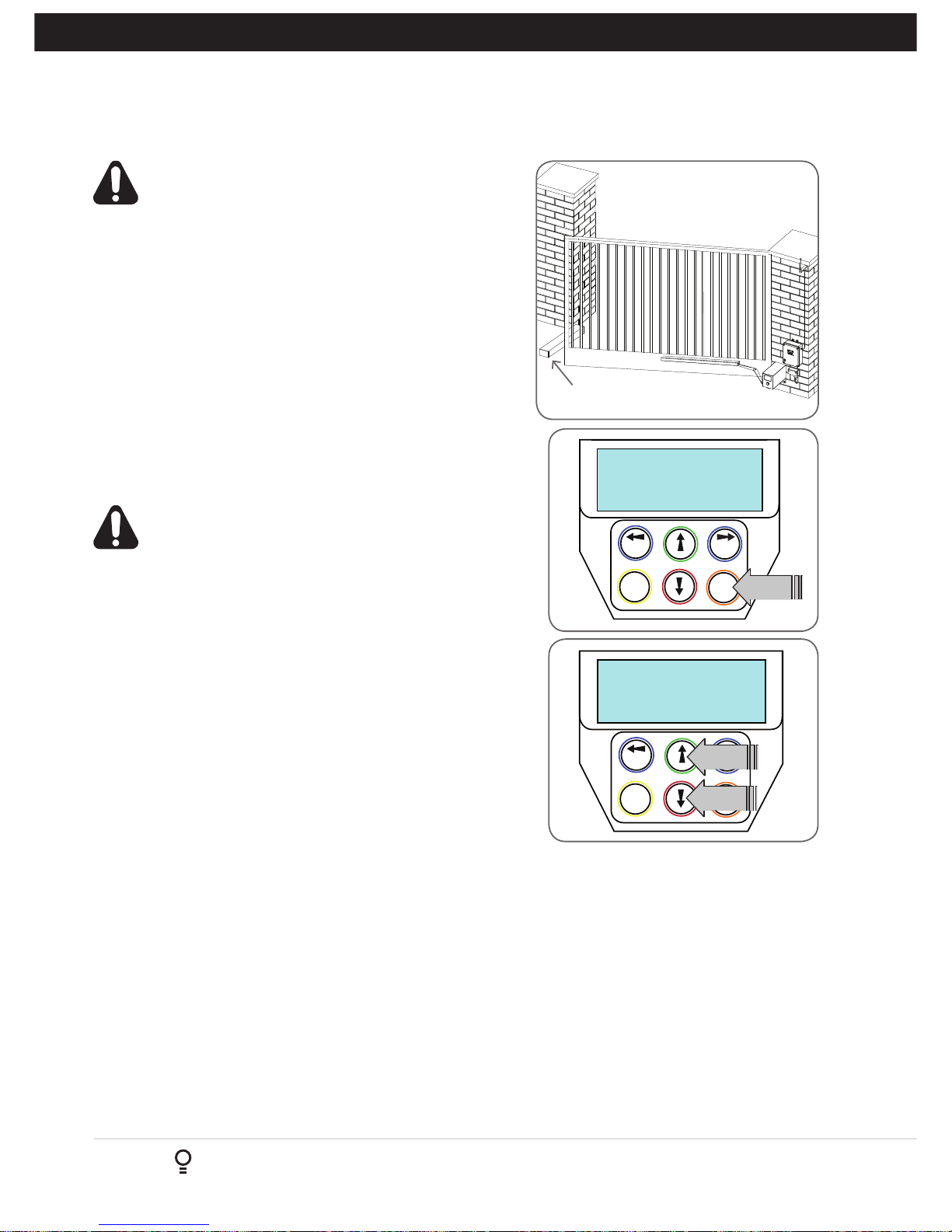
9.1 Testing Close Cycle (Single Swing Gates)
a. Press the OPEN button to open the gate.
b. Place a piece of timber approximately 40mm high on the ground
directly next to the closing pilon / fence (Fig. 9.1).
c. Press the CLOSE button to close the gate. The leaf of the gate
should strike the object and start to re-open.
9.2 Testing Open Cycle (Single Swing Gates)
a. Press the CLOSE button to close the gate.
b. Press the OPEN button to open the gate. When the gate reaches
the half open point, grab the side rail of the gate firmly and the
gate should stop.
c. If the gate does not reverse readily when closing, or stop when
opening, the force may be excessive and need adjusting.
WARNING! If the gate fails these tests, put the opener
into manual mode, only operate the gate by hand and
call for service.
Fig 9.1
40mm Block of wood
Safety Obstruction Force
The Safety Obstruction Force is calculated automatically during
setup. Adjusting this is normally only necessitated by environmental
conditions such as windy or dusty areas, and areas with extreme
temperature changes.
MENU 2
PREV NEXT
EXIT
SET
Current Trips
PRESS
PREV NEXT
EXIT
SET
PRESS
M1: CLOSE Margin
(Amps) 0.7
PRESS
Fig 9.2
Fig 9.3
9.3 Force Pressure For Close Cycle.
Navigating To “Current Trips”
a. Press NEXT or PREV to navigate to Menu 2 Current Trips.
b. Press SET (Fig.9.2)
c. MENU 2.1: CLOSE Margin is displayed (Fig. 9.3).
d. Press UP arrow to increase or DOWN arrow to decrease
the value.
e. Press SET to save the new value.
NOTE: For dual gates repeat the same process for Motor 2
f. Test the force again as per “Safety Obstruction Force Test”
in Section 9.1.
9.4 Force Pressure For Open Cycle.
Navigating To “Current Trips”
a. Press NEXT to navigate to the Menu 2 Current Trips.
b. Press SET (Fig. 9.2)
c. Press NEXT.
d. MENU 2.2: OPEN Margin is displayed.
e. Press UP arrow to increase or DOWN arrow to decrease
the value.
f. Press SET to save the new value.
NOTE: For dual gates repeat the same process for Motor 2
g. Test the force again as per “Safety Obstruction Force Test”
in Section 9.2
9.5 Reprofiling Travel
a. Reprofiling is a simplified way of re-learning the travel
characteristic of a previously setup Limit Switch travel
installation. Re-profiling can be used when the travel
characteristics of the gate(s) change due to mechanical
adjustments etc. To initiate a re-profile, simply locate
“MENU 10.3 Reprofile Travel”, press SET and follow
the prompts. The gate(s) will start to move and
re-calculate force margins. The gate(s) can move between
the open and close limit positions up to two (2) times
(depending on the position of the gate(s) and the power up
condition).
b. A single beep will be heard once the process is complete.
c. Test the force again as per “Safety Obstruction Force Test”
(Section 9.1 and 9.2).
Page 13
Owner Installation Instructions DCB-05V2 Gate Controller 13
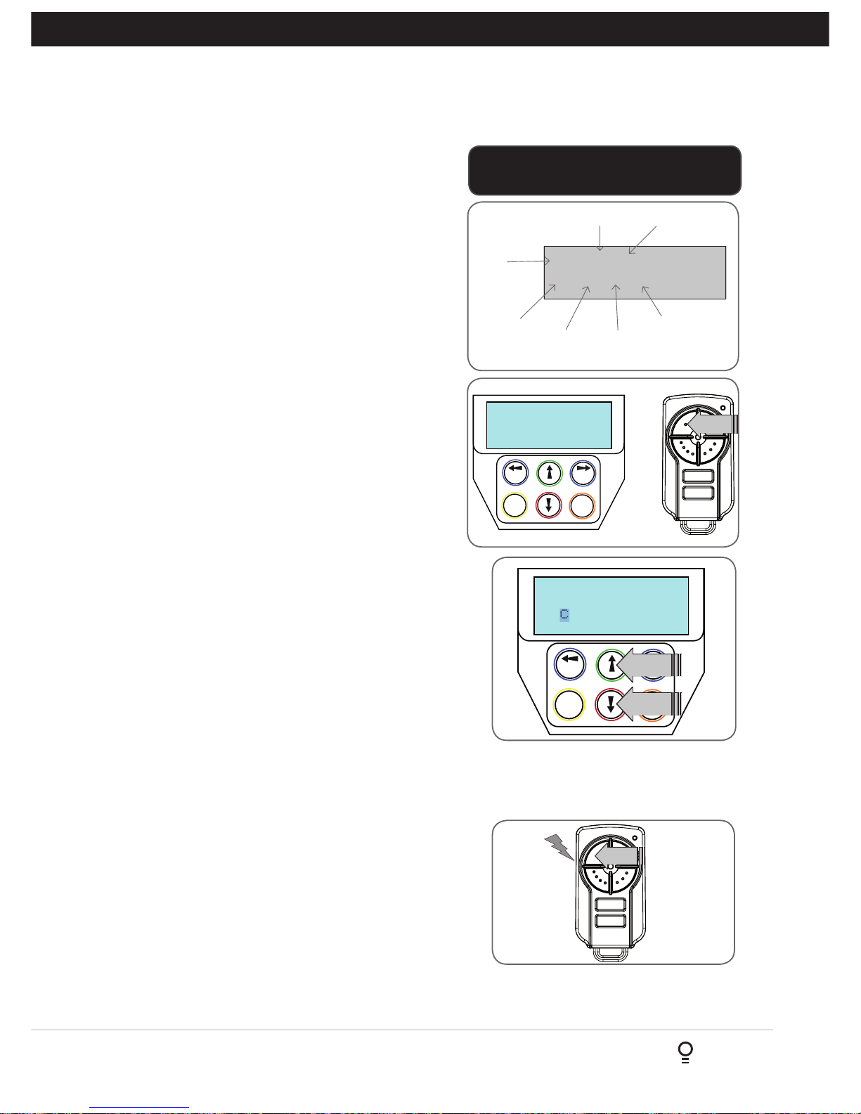
10. Coding Transmitter
DCB-05V2 can store up to thirty (30) transmitters in its memory.
Each transmitter can be allocated an alpha-numeric ID label up to
eleven (11) characters in length and each button can be assigned
to one of several control functions. The settings for a transmitter
are represented in (Fig. 10.1). It shows the transmitter’s store
number, ID label or serial number and the functions assigned to
each of its four buttons. To toggle between ID/SN display, press
UP/DOWN with the cursor on the ID/SN indicator. The procedures
below code, delete, replace, edit and copy transmitter records.
10.1 Coding Transmitter Button
Navigating To Menu 1 “Code Transmitter”
a. Press NEXT to navigate to Menu 1.
b. Press SET to enter the code set procedure.
Storing Transmitter Code
a. The controller will prompt to press one of the transmitter’s
buttons.
b. Press the transmitter button you wish to use to operate the Gate
Opener (e.g. button 1) (Fig. 10.2) .
c. Press the same transmitter button again as prompted by the
display.
10.2 Selecting Function Of The Button
The controller will now show the transmitter’s record, with a
cursor on the field for the button being coded (Fig. 10.3).
Use UP/DOWN arrows to select the function for the button.
Available functions:
VAC (Vacation Mode) LGT (Courtesy Light)
STP (Stop) OPN (Open)
CLS (Close) SWP (Swipe)
PED (Pedestrian access) OSC (Open/Stop/Close)
OFF (No action)
Press SET to save the settings or EXIT to abort without saving.
10.3 Returning To Main Screen
The “Code Transmitter” menu will now be shown. Press EXIT to
return to the MAIN SCREEN and test the transmitter.
PREV NEXT
EXIT
SET
OSC OFF OFF OFF
# 1[No Name]
PRESS
PRESS
PREV NEXT
EXIT
SET
Button! LIST>
Press Tx’er
PRESS
Fig 10.2
Fig 10.3
123
ID
Name/SN
OSC PED LGT VAC
I.D label/Serial
number
Button 4
function
Button 3
function
Button 2
function
Button 1
function
Store
number
ID/SN display
indicator
Fig 10.1
IMPORTANT NOTE: Only TrioCodeTM128
Technology Transmitters are compatible with
this product.
11. Remotely Coding Transmitters
If a transmitter is already coded into the opener, additional transmitters
can be coded without being in direct contact with the DCB-05V2.
NOTE: Only the function of the existing transmitter button can
be assigned to new transmitter. Please read instructions prior to
proceeding - there is a time-out facility for security reasons.
11.1 Selecting The Function To Be Coded
a. Using the existing transmitter, operate the gate with the
transmitter button which has the function to be coded
(e.g. Button 1 has been coded with the OSC function assigned).
b. If the button’s function activates the gate (PED, SWP, OSC, CLS, STP
or OPN) wait for the gate to complete its cycle.
PRESS
Existing
transmitter
Fig 11.3
Page 14
14
DCB-05V2 Gate Controller Owner Installation Instructions
PRESS
New
transmitter
Fig 11.3
NOTE: When a transmitter is remotely coded, its ID label is set to that
of the existing transmitter. If the existing transmitter does not have an
ID label assigned, then the ID label of the new transmitter is set to:
R/C Tx ###, where ### is the existing transmitters store number. This
ensures that the originator of any remotely coded transmitter can be
identified.
DCB-05V2 can be instructed, via its pedestrian control feature, to partly open and provide pedestrian access but prevent
vehicle access. This is achieved by partly opening the motor 1 gate leaf. If dual motors are used, motor 2’s gate leaf is
held closed. The partly open position of motor 1’s gate leaf is initially set to a position halfway between open and closed.
This initial position can be adjusted by the installer to any position within the gates travel range by selecting a pedestrian
access travel time (from closed). The setting is accessed from “MENU 10.4 Set Pedestrian”. The time is adjustable in
1 second steps.
12. Setting Pedestrian Position
PED’N Opening
TIME 5
PREV NEXT
EXIT
SET
Fig 12.1
Fig 12.2
MENU 10.4
SET PEDESTRIAN
PREV NEXT
EXIT
SET
PRESS
NOTE: Before setting the pedestrian access position the gate
must be in the fully closed position. As with the Setting Travel
Limit procedure, a transmitter can be used to complete the
pedestrian position setting procedure.
12.1 Setting the Pedestrian Position
Navigating to “Menu 10.4 Set Pedestrian”
a. Press PREV to navigate to Menu 10.
b. Press SET - MENU 10.1 is displayed.
c. Press NEXT to go to MENU 10.4.
d. Press SET to enter Set Pedestrian procedure (Fig. 12.1).
Setting pedestrian position
a. Press UP or DOWN arrows to adjust pedestrian drive time.
b. Press SET to record position
c. Press transmitter coded for pedestrian function or push button
wired into pedestrian input to test.
12.2 Checking Pedestrian Position
When activated by a transmitter button which is coded as Ped
mode, the opener drives the gate to the preset position. Ped
Mode’s active status is indicated on the display (Fig. 12.2). If a
Ped Mode button is pressed while the gate is moving, the gate
will stop. If a Ped Mode button is pressed when the gate is in the
Ped position, then the gate will close.
12.3 Error Displays
During the above procedure many error checks are performed. If
an error is detected, a message will be displayed indicating the
error.
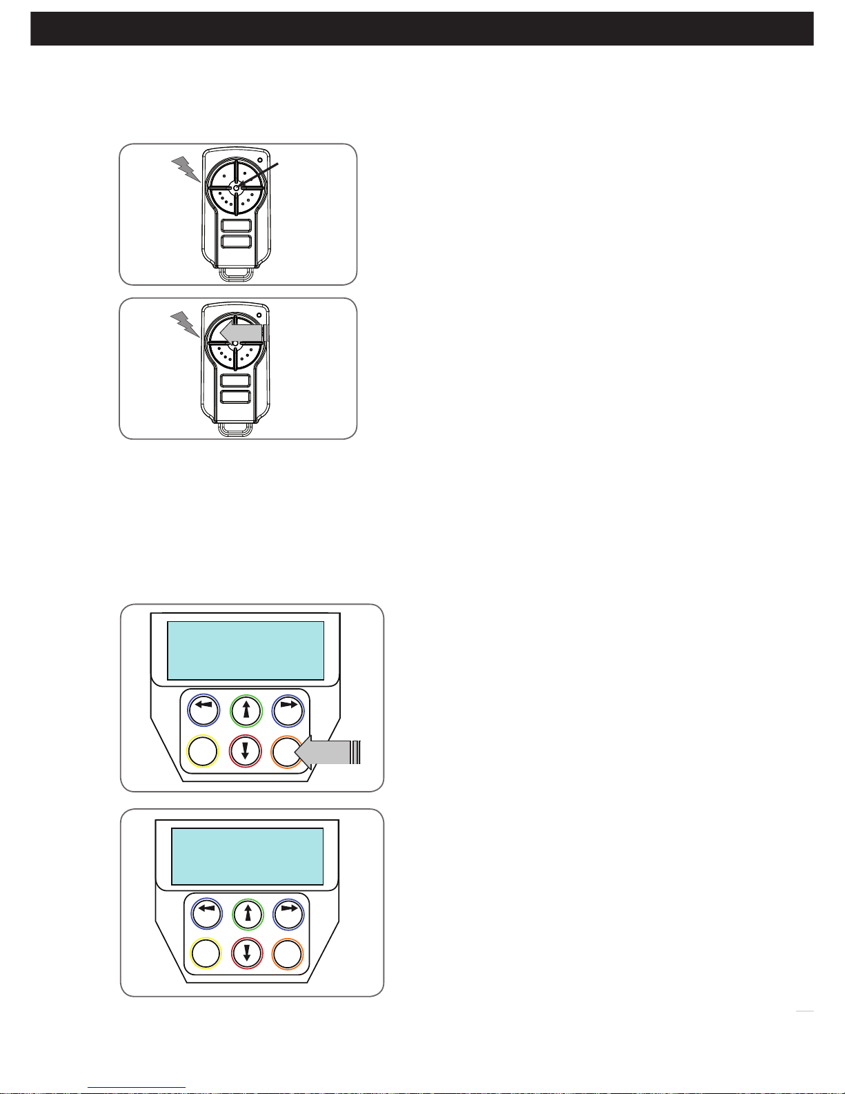
11.2 Activate Remote Code Set Mode
a. Use a small pin to press and hold through the Coding Hole of the
existing transmitter for 2 seconds (Fig. 11.2).
b. Within 10 seconds, press the button on the new transmitter you
wish to code for 2 seconds (Fig. 11.3).
c. Press the same button again (within 10 seconds)for confirmation.
d. Test Operation. The new transmitter button should now function as
the existing transmitter.
11. Remotely Coding Transmitters
Existing
transmitter
Fig 11.2
Page 15

Owner Installation Instructions DCB-05V2 Gate Controller 15
WARNING! The Auto-Close function is not
available unless Safety Beams are installed.
13.1 Setting Up Standard Auto-Close
Menu 3. Auto-Close Times
Auto-Close mode is a function that automatically closes
the gate a preset time after the Safety Beam recognise that
a vehicle has left the gateway. The Auto-Close timer only
starts after the Safety Beam path is broken and the AutoClose timer has been set. If the Safety Beam path is not
broken, the gate will remain open until the path is broken.
If the opener incurs a physical obstruction (i.e. not from the
Safety Beam) while closing, the gate will re-open and not
Auto-Close until the Safety Beam path is broken again.
Menu 3.1 Auto-Close
This mode is selected by entering a non-zero time for the
STD Auto-Close parameter. When selected, the gate will
Auto-Close after being fully opened (except when the gate
has reversed to the open position after a motor obstruction
or overload unless A/C after open and/or close Obstruction
are selected). Countdown is suspended by: S.B., OPN or
SWP input being active. The countdown is aborted if the
STP input is activated. If the gate is already open and the
OPN or the SWP input is activated, then the countdown
will start.
13.2 Safety Beam Triggered Auto Close
Menu 3.2 (SB AC Trig)
This mode is selected by entering a non-zero time for the
“Safety Beam Auto-Close” parameter. This mode is used
to Auto-Close the gate but only after an object has passed
through the gateway and has triggered the Safety Beam
input. Any Safety Beam or combination of Safety Beams
can be configured to activate Safety Beam Auto-Close
mode and combinations are:
One Beam only
i. Safety Beam 1
ii. Safety Beam 2
Either Beam
i. Safety Beam 1 or Safety Beam 2
Combination
ii. Safety Beam 1 and Safety Beam 2
iii. Safety Beam 2 then Safety Beam 1
NOTE: The swipe input can be used to clear the Safety
Beam triggered status so that the Safety Beam input must
be activated again before the countdown will start. As with
the other Safety Beam modes, the STP input will abort
countdown and the OPN and SWP inputs will restart the
countdown if the gate is OPEN.
13. Auto-Close Mode
13.3 Pedestrian Auto-Close
Menu 3.3 Pedestrian Auto-Close
This mode is selected by entering a non-zero time for the
“Ped’n A/C” parameter. When selected, the gate will AutoClose after being opened for pedestrian access unless it
was following a reverse from an obstruction.
Menu 3.4 (Safety Beam) Pedestrian Triggered Auto-Close
This mode is selected by entering a non-zero time for
the “Safety Beam Pedestrian Auto-Close” parameter.
Any Safety Beam or combination of Safety Beams can be
configured to activate Safety Beam Auto-Close mode and
combinations are:
One Beam only
iv. Safety Beam 1
v. Safety Beam 2
Either Beam
i. Safety Beam 1 or Safety Beam 2
Combination
ii. Safety Beam 1 and Safety Beam 2
iii. Safety Beam 2 then Safety Beam 1
13.4 Auto-Close After Obstruction:
Two parameters are provided to enable the Auto-Close
feature to be activated after obstructions and power up.
Normally the Auto-Close feature is not enabled after
obstructions for safety reasons. Safety Beams must be
used for these features to be activated.
Menu 3.5
This mode enables the Auto-Close feature to be activated
when a close obstruction occurs (requires Safety Beams).
Menu 3.6
This mode enables the Auto-Close feature to be activated
when an open obstruction occurs.
Menu 3.7
This mode enables Auto-Close feature after power up.
Page 16
16
DCB-05V2 Gate Controller Owner Installation Instructions
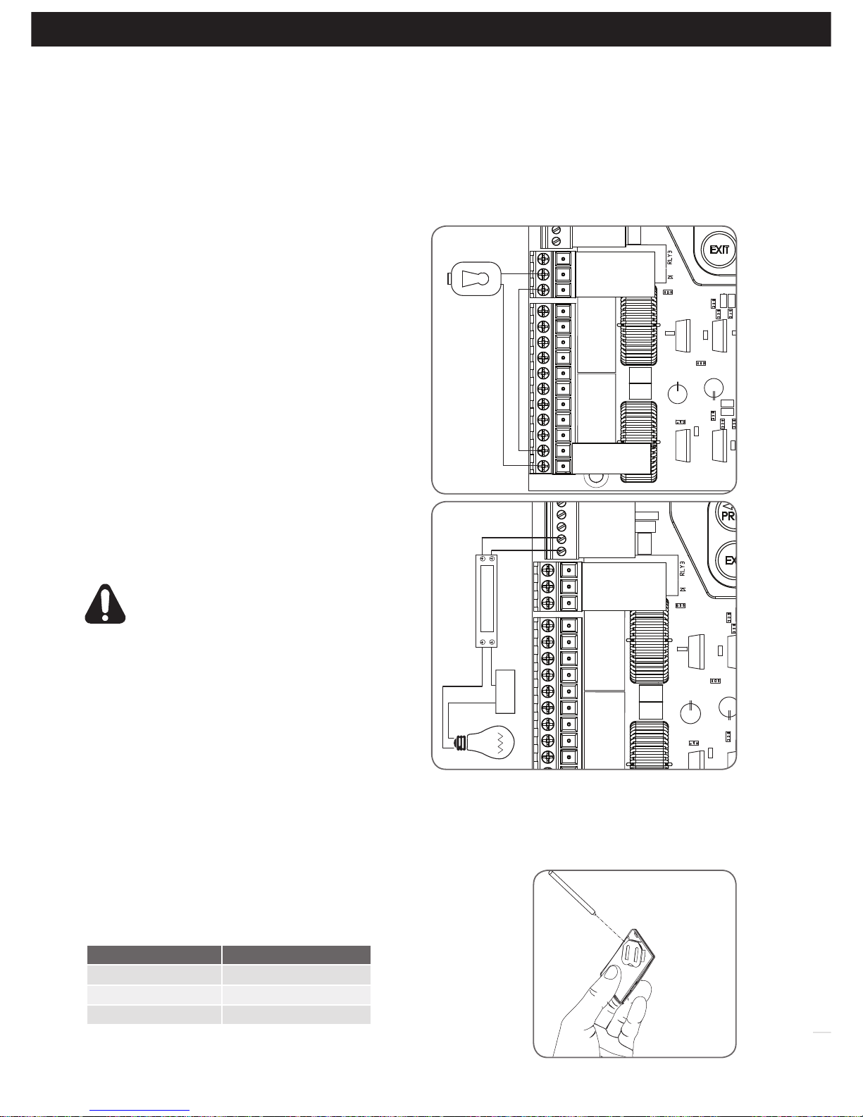
14.2 Fitting Courtesy Lights
An AC or DC courtesy light can be activated via an output
on the gate opener control board. Connect the light as per
the diagram. (Fig. 14.2)
WARNING: A qualified electrician must perform
the installation where 240V AC power is used.
Menu 5. Light Times
a. Press NEXT or PREV on the wall control unit to navigate
to Menu 5 Light/Lock Times.
b. Press SET to select the sub menu.
c. Press NEXT or PREV to navigate through the sub menu.
d. Press OPEN to increase or CLOSE to decrease the time.
e. Press SET to save the new time.
f. Press the EXIT button two times to exit.
g. Test the light operation.
14. Accessories Installation
SAFETY B2
SAFETY B1
OV
AUX
OPEN
STOP
CLOSE
OSC
SWIPE
PEDESTRIAN
OV
V+
OUT2
OUT1 N/C
OUT1 COMMON
OUT1 N/O
LIGHT RELAY MODULE
POWER
SUPPLY
Wiring Output1 And Output2
Outputs 1 and 2 are used to control a lock and a light. Which output is to control which function and the way it is controlled
is programmable. If using these outputs make sure that the functions are configured for correct operation prior to setting
the travel limits. OUTPUT1 is a relay output with high current capability. OUTPUT2 is used to activate an optional external
relay module (RO-1) which in turn is used to switch the load.
14.1 Fitting Solenoid Or Magnetic Locks
Install the lock mechanism on the gate as per the manufacturers
instructions. See Fig. 14.1 for the wiring diagram.
Menu 4. Lock Times
Lock output can be programmed for both hold and pulse
mode. The operation of the lock can be programmed to
activate prior to the gate and behave differently on open
cycles to that on close cycles.
a. Press NEXT or PREV on the wall control unit to navigate to
Menu 4 Lock Times.
b. Press SET to select the sub menu.
c. Press NEXT or PREV to navigate through the sub menu.
d. Press OPEN to increase or CLOSE to decrease the time.
e. Press SET to save the new time.
f. Press the EXIT button two times to exit and test the locks
operation.
SAFETY B2
SAFETY B1
OV
AUX
OPEN
STOP
CLOSE
OSC
SWIPE
PEDESTRIAN
OV
V+
OUT2
OUT1 N/C
OUT1 COMMON
OUT1 N/O
Pulse Lock
V PWR
OV
Fig 14.1
Fig 14.2
15.1 Removing the Battery From the Transmitter
(Battery Type: 3V Lithium Battery CR2032).
Use a non-metallic object (e.g. pen) to remove the battery. (Fig. 15.1). To
test the battery is working, press and hold a transmitter button; (Fig. 15.2).
Light Status Battery Status
Solid OK
Flashing Requires replacement
No light Requires replacement
REPLACE
BATTERY WITH
CR2032 ONLY
Fig 15.1
Fig 15.2
Use a pen
to push the
battery down
through the
side opening
to release
battery
15. Battery Replacement
Page 17
Owner Installation Instructions DCB-05V2 Gate Controller 17
Technical Specifications
Protection rating: IP56 (only when unit is sealed with correct cable glands)
24VDC accessory output 24VDC (unfiltered) 3Amp maximum
Secondary voltage: 24V AC
Motor voltage: 12 to 24V DC @ 10AMPS max combined
Receiver type: TrioCode™128 Technology
Receiver code storage capacity:
30 x 4 Button Transmitter Codes
Transmitter frequency: 433.92 MHz
Coding type: Hopping Code
No. of code combinations: Over 100 billion random codes
Code generation: Non-linear encryption algorithm
Transmitter battery: CR2032
NOTE: Specifications are subject to change without notice.
17. Specifications
When batteries reach the end of their usual life in accordance with
Australian Battery Recycling Initiative please follow the next simple
steps for protecting the environment.
Refer to the Automatic Technology website for information on where
to recycle batteries in Australia.
DO NOT throw the batteries in
municipal waste. This symbol of the
crossed out wheeled bin indicates that
the battery should not be placed in
the municipal waste. Check your local
regulations for appropriate disposal of
the batteries.
Recycling all batteries will have other environmental and social benefits:
• Some batteries are less toxic but hazardous for other reasons.
Lithium batteries can explode or catch fire in landfill, while button
cells are dangerous if swallowed by children. Recycling offers a safe
and environmentally responsible solution for end of life batteries.
• Battery recycling recovers non-renewable materials such as lead,
cadmium, stella, zinc, manganese, cobalt, silver, plastics and rare
earth elements.
• Removal of batteries and other hazardous household products from
household waste facilitates the recovery of organic materials through
alternative waste technologies such as composting. Batteries and
heavy metals are known contaminants in compost.
• The community supports recycling because it reduces waste to
landfill and achieves environmental benefits.
WARNING! Prior to disposal,
recycling, or collection, all battery
terminals must be securely insulated
with a non conductive material to
prevent any two batteries from short
circuiting and generating heat during
storage or transport. Battery terminals
may be insulated with electrical tape;
or batteries may be individually
packaged in a non conductive material
(e.g., plastic bag or original packaging).
16. Battery Disposal
Page 18
18
DCB-05V2 Gate Controller Owner Installation Instructions
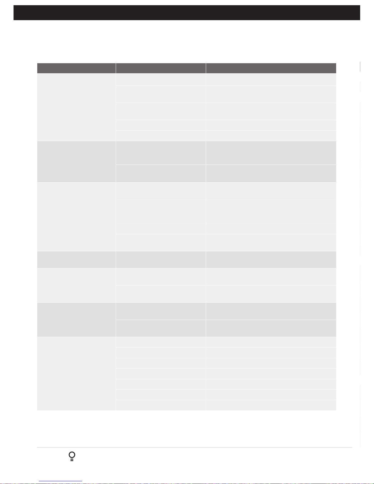
Symptom Possible cause Remedy
Gate will not operate Mains power not switched on. Switch on mains power.
Control Box not wired correctly Check all wiring from motor and microswitches to
the control board are sound (Section 5)
Opener motor is disengaged Check that the motor is engaged for automatic
operation
Gate is obstructed. Remove obstruction.
The opener is in “Vacation Mode” Turn off “Vacation Mode”(Appendix C Menu 7.4).
Gate starts to close but
automatically reverses to
open position
Adverse weather conditions (wind
or cold) causing gate to stiffen and
become tight in the tracks.
Increase force margin setting (Section 9.4)
Possible obstruction in the
doorway.
Remove obstruction
Gate operates from control
box but not from transmitter
Transmitter code not stored in
memory.
Code transmitter in to openers memory.
(Section 10.1)
Transmitter does not contain
TrioCode™128 Technology
Check the transmitter. It should have grey buttons
and the model number should display V2. Contact
dealer for support if otherwise.
Flat battery in transmitter Replace battery (Section 15)
Antenna behind structure (gate or
fence) or not in line of sight
Ensure Antenna is in line of sight (Section 4.2)
Gate does not close with
transmitter
Safety Beam not working properly. Make sure Safety Beams are operational. and no
dirt is on the lens.
Gate will not close fully. Gate limit positions need to be
reset.
Reset limits positions.
Gate obstructed and reverses Clear obstruction or adjust force margin
(Section 9.3)
Door will not open fully. Gate limit positions need to be
reset.
Reset limits positions. (Section 8)
Gate obstructed. Clear obstruction or adjust force margin
(Section 9.3)
Auto-Close not working Safety Beam not installed. Install Safety Beam. (Refer to Safety Beam Manual)
Safety Beam or wiring faulty. Repair Safety Beam or replace wiring.
Safety Beam not aligned correctly. Re-align optics.
Safety Beam is obstructed. Remove obstruction from path of Safety Beams.
Gate obstructed when closing. Remove obstruction.
Auto-Close time not set. Set Auto-Close times (Section 13.3).
Auto-Close mode not set Set Auto-Close mode. (Section 13.2)
18. Troubleshooting
Parameter Min Max Default Step Unit Menu Section
Menu 1 - Code Transmitter
STORING TRANSMITTERS 0.0 511 1 10.1
Menu 2 - Current Trips
Parameter (Limit Switch)
M1 MARGIN
Sets obstruction detection margin for M1
M2 MARGIN
Sets obstruction detection margin for M2
SETTLE TIME disable the obstruction detection in the start of the
cycle
Parameter (AMP Limits
STOP DETECT MARGIN AMPS 0.0 5.0 1.5 0.1 AMPS 2.4 Appendix H
Motor 1 Open Limit AMPS Sets Motor 1 open limit detection current 0.0 8.0 AUTO 0.1 AMPS 2.5 Appendix H
Motor 1 Close Limit AMPS Sets Motor 1 close limit detection current 0.0 8.0 AUTO 0.1 AMPS 2.6 Appendix H
Motor 2 Open Limit AMPS Sets Motor 2 open limit detection current 0.0 8.0 AUTO 0.1 AMPS 2.7 Appendix H
Motor 2 Close Limit AMPS Sets Motor 2 close limit detection current 0.0 8.0 AUTO 0.1 AMPS 2.8 Appendix H
Maximum startup amps sets maximum permitted starting current of
motors
Parameter (timed travel)
Cutout AMPS maximum motor current permitted after startup 0.0 10.0 10.0 0.1 AMPS 2.10 Appendix H
Menu 3 - Auto Close
STD AUTO-CLOSE TIME
Sets and enables the standard Auto-Close time
SAFETY BEAM AUTO-CLOSE TIME Sets and enables the SB
triggered Auto-Close time
PEDESTRIAN AUTO-CLOSE TIME Sets and enables the Pedestrian
Auto-Close time
SAFETY BEAM PEDESTRIAN AUTO-CLOSE TIME Sets and
enables the SB Pedestrian Auto-Close time
AUTO-CLOSE AFTER CLOSE OBSTRUCTION
Enables Auto-Close feature after close obstructions
AUTO-CLOSE AFTER OPEN OBSTRUCTION
Enables Auto-Close feature after open obstructions
AUTOCLOSE AFTER POWERUP
Enables autoclose feature after powerup
Menu 4 - Lock Times
OPEN LOCK TIME Set the time the lock is activated for on open
cycles
CLOSE LOCK TIME Set the time the lock is activated for on close
cycles
PRE-OPEN LOCK TIME Time the lock is activated for prior to
opening
PRE-CLOSE LOCK TIME Time the lock is activated for prior to
closing
Page 19
Owner Installation Instructions DCB-05V2 Gate Controller 19
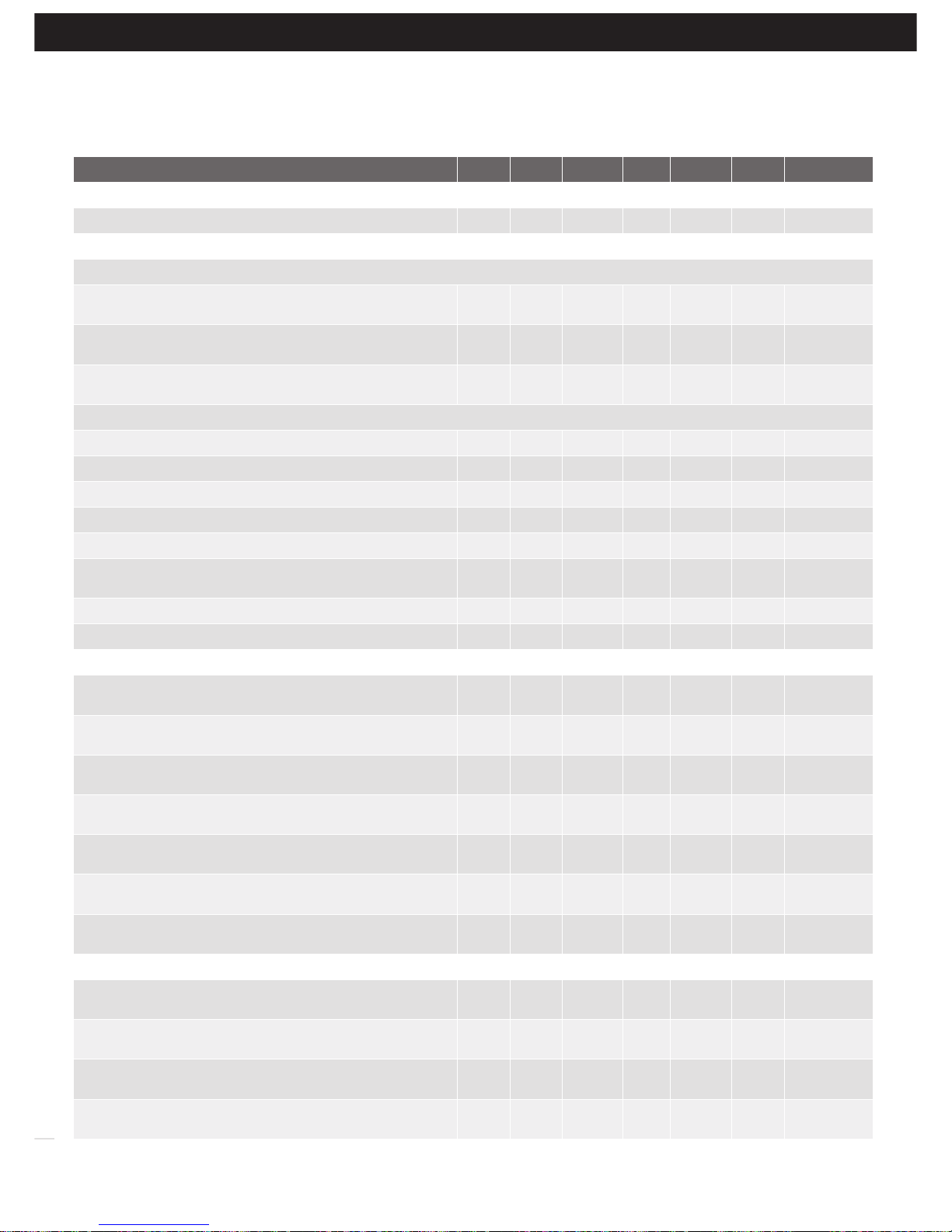
OPERATIONAL BUTTONS:
1. Press PREV/NEXT buttons move to Left/Right.
2. Press OPEN/CLOSE buttons to change setting.
3. Press SET button to save changes.
4. Press EXIT to return to MENU without saving changes.
19. Appendix
A - Console Menu Structure
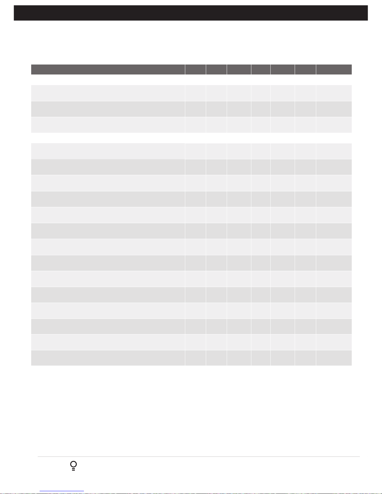
Parameter Min Max Default Step Unit Menu Section
Menu 1 - Code Transmitter
STORING TRANSMITTERS 0.0 511 1 10.1
Menu 2 - Current Trips
Parameter (Limit Switch)
M1 MARGIN
Sets obstruction detection margin for M1
0.0 5.0 0.7 0.1 AMPS 2.1 9.3
M2 MARGIN
Sets obstruction detection margin for M2
0.0 5.0 0.7 0.1 AMPS 2.2 9.3
SETTLE TIME disable the obstruction detection in the start of the
cycle
0.1 2.0 1.0 0.1 SEC 2.3
Parameter (AMP Limits
STOP DETECT MARGIN AMPS 0.0 5.0 1.5 0.1 AMPS 2.4 Appendix H
Motor 1 Open Limit AMPS Sets Motor 1 open limit detection current 0.0 8.0 AUTO 0.1 AMPS 2.5 Appendix H
Motor 1 Close Limit AMPS Sets Motor 1 close limit detection current 0.0 8.0 AUTO 0.1 AMPS 2.6 Appendix H
Motor 2 Open Limit AMPS Sets Motor 2 open limit detection current 0.0 8.0 AUTO 0.1 AMPS 2.7 Appendix H
Motor 2 Close Limit AMPS Sets Motor 2 close limit detection current 0.0 8.0 AUTO 0.1 AMPS 2.8 Appendix H
Maximum startup amps sets maximum permitted starting current of
motors
0.0 6.0 5.0 0.1 AMPS 2.9 Appendix H
Parameter (timed travel)
Cutout AMPS maximum motor current permitted after startup 0.0 10.0 10.0 0.1 AMPS 2.10 Appendix H
Menu 3 - Auto Close
STD AUTO-CLOSE TIME
Sets and enables the standard Auto-Close time
0.0 300.0 0.0 1.0 Sec 3.1 13.1
SAFETY BEAM AUTO-CLOSE TIME Sets and enables the SB
triggered Auto-Close time
0.0 60.0 0.0 1.0 Sec 3.2 13.2
PEDESTRIAN AUTO-CLOSE TIME Sets and enables the Pedestrian
Auto-Close time
0.0 60.0 0.0 1.0 Sec 3.3 13.3
SAFETY BEAM PEDESTRIAN AUTO-CLOSE TIME Sets and
enables the SB Pedestrian Auto-Close time
0.0
60.0 0.0 1.0 Sec 3.4 13.3
AUTO-CLOSE AFTER CLOSE OBSTRUCTION
Enables Auto-Close feature after close obstructions
Off On Off 3.5 13.4
AUTO-CLOSE AFTER OPEN OBSTRUCTION
Enables Auto-Close feature after open obstructions
Off On Off 3.6 13.4
AUTOCLOSE AFTER POWERUP
Enables autoclose feature after powerup
Off On Off 3.7 13.4
Menu 4 - Lock Times
OPEN LOCK TIME Set the time the lock is activated for on open
cycles
0.0 Hold 0.5 0.1 Sec 4.1 14.1
CLOSE LOCK TIME Set the time the lock is activated for on close
cycles
0.0 Hold 0.5 0.1 Sec 4.2 14.1
PRE-OPEN LOCK TIME Time the lock is activated for prior to
opening
0.0 25.5 0.0 0.1 Sec 4.3 14.1
PRE-CLOSE LOCK TIME Time the lock is activated for prior to
closing
0.0 25.5 0.0 0.1 Sec 4.4 14.1
Page 20
20
DCB-05V2 Gate Controller Owner Installation Instructions
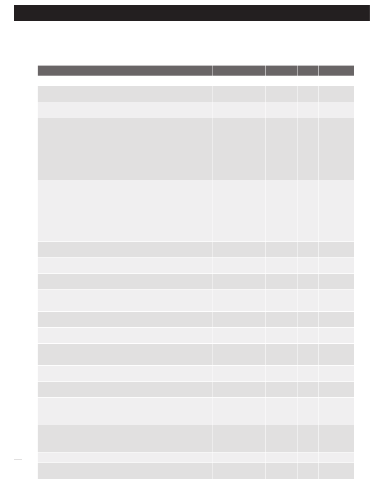
Parameter Min Max Default Step Unit Menu Section
Menu 5 - Light Times
ON AFTER CYCLE LIGHT TIME - Time light remains on for after a
cycle
0 255 60 1 Sec 5.1 14.2
ON BEFORE OPEN CYCLE LIGHT TIME
Minimum time light is activated for prior to opening
0 255 0 1 Sec 5.2 14.2
ON BEFORE CLOSE CYCLE LIGHT TIME
Minimum time light is activated for prior to closing
0 255 0 1 Sec 5.3 14.2
Menu 6 - Motor Settings
CLOSE SYNC DELAY TIME
Time delay between M2 and M1 closing
0.0 25.5 2.0 0.1 SEC 6.1 Appendix C
OPEN SYNC DELAY TIME
Time delay between M1 and M2 opening
0.0 25.5 2.0 0.1 SEC 6.2
OPEN SPEED VOLTS
Voltage applied to motors when opening
12 24 22 1 VOLTS 6.3
CLOSE SPEED VOLTS
Voltage applied to motors when closing
12 24 20 1 VOLTS 6.4
SLOW SPEED VOLTS
Voltage applied to motors when slowing down
6 24 8 1 VOLTS 6.5
SLOW TIME
The time between slow down and end of cycle
0.1 10.0 3.0 0.1 SEC 6.6
HOMING / SETUP SPEED VOLTS
Voltage applied to motors when setting up the travel limits
12 24 Norm 1 Volts 6.7
STOP PAUSE TIME
Pause time used between motor direction changes
0.0 2.0 0.3 0.1 SEC 6.8
M1 NORMAL OPEN TIME
Normal open time for motor 1
0.0 60.0 0.0 0.1 SEC 6.9
M1 NORMAL CLOSE TIME
Normal close time for motor 1
0.0 60.0 0.0 0.1 SEC 6.10
M2 NORMAL OPEN TIME
Normal open time for motor 2
0.0 60.0 0.0 0.1 SEC 6.11
M2 NORMAL CLOSE TIME
Normal close time for motor 2
0.0 60.0 0.0 0.1 SEC 6.12
M1 CLOSE DELAY
Close Delay for Motor 1
0.0 25.5 0.0 0.1 SEC 6.13
MAX OVERRUN TIME
Extra time allowed for cycle to complete (beyond normal cycle time)
0 60 5 1 6.14
A - Console Menu Structure
Appendix
Page 21
Owner Installation Instructions DCB-05V2 Gate Controller 21
A - Console Menu Structure
Appendix
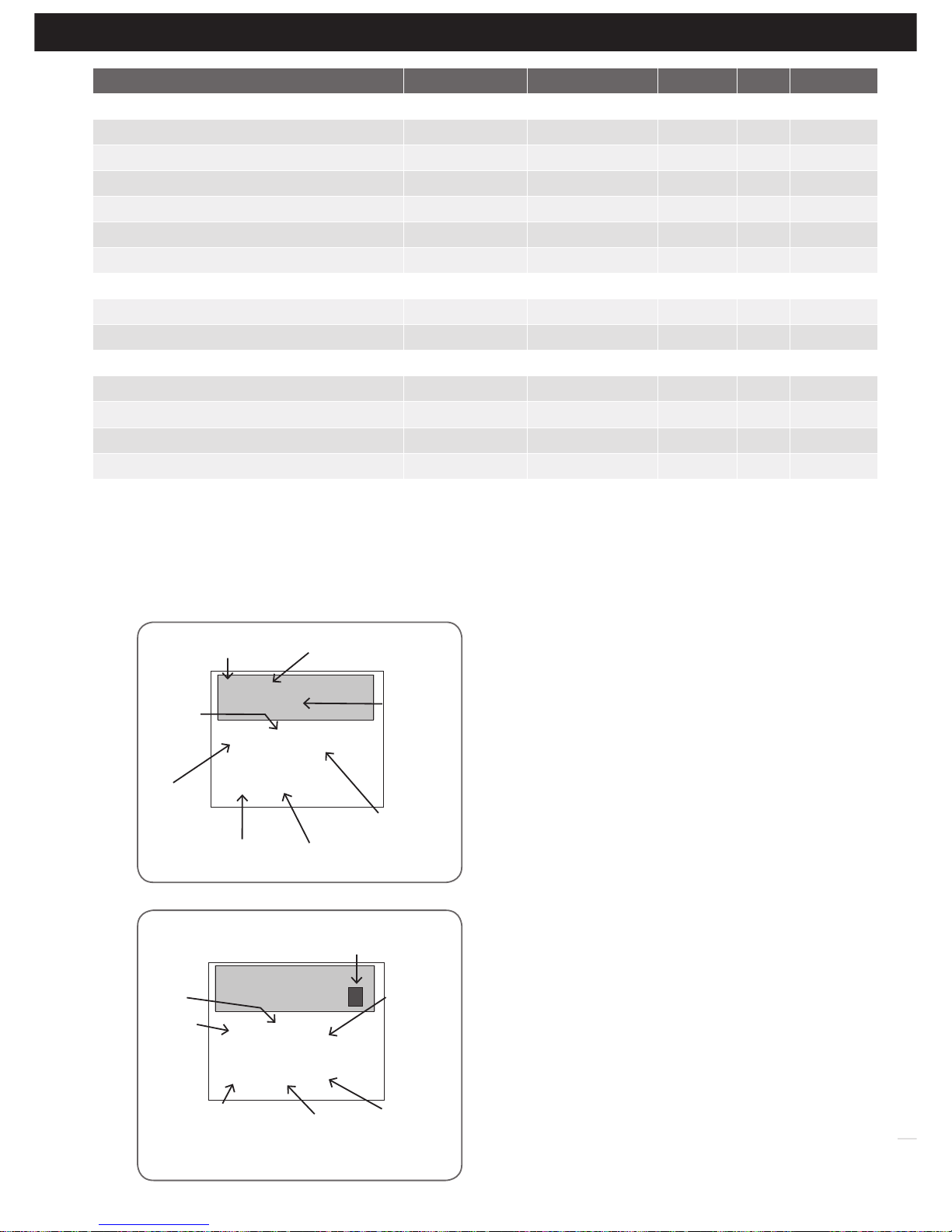
Parameter Min Max Default Menu Section
Menu 7 - Operating Modes
SB1 TYPE 2 WIRE
3 WIRE
2 WIRE
3 WIRE
7.1 Appendix C
SB2 TYPE 2 WIRE
3 WIRE
2 WIRE
3 WIRE
7.2 Appendix C
SB1 INPUT MODE
Sets the Input mode for Safety Beam 1.
Only one option can be selected.
NOT USED,
CLS TO REV
CLS TO STOP
OPN/CLS TO
STOP
OPEN INPUT
SWIPE INPUT
CLOSE INPUT
PED INPUT
DISABLED
NOT USED,
CLS TO REV
CLS TO STOP
OPN/CLS TO STOP
OPEN INPUT
SWIPE INPUT
CLOSE INPUT
PED INPUT
DISABLED On
NOT USED 7.3 Appendix C
SB2 INPUT MODE
Sets the Input mode for Safety Beam 2.
Only one option can be selected.
NOT USED,
CLS TO REV
CLS TO STOP
OPN/CLS TO
STOP
OPEN INPUT
SWIPE INPUT
CLOSE INPUT
PED INPUT
DISABLED
NOT USED,
CLS TO REV
CLS TO STOP
OPN/CLS TO STOP
OPEN INPUT
SWIPE INPUT
CLOSE INPUT
PED INPUT
DISABLED On
NOT USED 7.4 Appendix C
PED INPUT = SWIPE MODE Selects PED input
functions as pedestrian access swipe input
Off On Off 7.5 Appendix C
OPN INPUT N/C OPERATION
Selects operating polarity of OPN input
Off On Off 7.6 Appendix C
STP INPUT N/C OPERATION
Selects operating polarity of STP input
Off On Off 7.7 Appendix C
AUX INPUT OPERATION LIGHT
MOTOR
ENGAGED
LIGHT
MOTOR ENGAGED
LIGHT 7.8 Appendix C
VACATION MODE
Selects vacation mode - disables remote control
Off On Off 7.9 Appendix C
REMOTE CODE ENABLED
Selects remote transmitter coding function
On Off On 7.10 Appendix C
BATTERY/SOLAR MODE
Selects Battery Backup/Solar operation
BATTERY
ENABLED
SOLAR ENABLED
BATTERY ENABLED
SOLAR ENABLED
BATTERY
ENABLED
7.11 Appendix C
PASSWORD
Selects password protection for all changes
Off On
Off 7.12 Appendix C
TX # GROUPING
Selects transmitter number group display for
mat.
Off On Off 7.13 Appendix C
OUTPUTS 1 MODE
Selects function of OUTPUT1
LOCK DRIVE
LIGHT DRIVE
3 WIRE SB 0V
NOT USED
LOCK DRIVE
LIGHT DRIVE
3 WIRE SB 0V
NOT USED
7.14 Appendix C
OUTPUTS 2 MODE
Selects function of OUTPUT2
LOCK DRIVE
LIGHT DRIVE
3 WIRE SB 0V
NOT USED
LOCK DRIVE
LIGHT DRIVE
3 WIRE SB 0V
NOT USED
7.15 Appendix C
FAULT AUTO RESET Off On Off 7.16 Appendix C
SBFEC MODE AVAILABLE
DISABLED
AVAILABLE
DISABLED
AVAILABLE 7.17 Appendix C
Page 22
22
DCB-05V2 Gate Controller Owner Installation Instructions
This section illustrates how to locate, view and adjust
parameters.
Locating parameters
Refer to Appendix A for Consile Menu Structure. Locate the required
parameter and note the MENU number. The example used in
(Fig. B.1) displays “CLOSE LOCK TIME”
Changing Setting
a. Press NEXT/PREV to navigate to the required menu.
b. Press SET to show the sub-menu.
c. Press NEXT/PREV to go to the required sub-menu.
d. Press OPEN/CLOSE to change parameter setting. Holding
the button down causes the parameter’s value to change
rapidly. The longer the button is held the faster the value
changes.
e. Press SET to SAVE setting.
Reload Default Setting
a. Press NEXT/PREV buttons to display LOAD DEFAULT
screen.
b. Press SET to load the default value.
Return To Menu
If the parameter values are not to be changed, press EXIT to
return to sub menu. Press EXIT again to return to the MAIN
SCREEN.
2: Close Lock
Time (SEC) 0.5
2: Close Lock
Time (SEC) 0.5
Fig B.1
Fig B.2
B - Viewing and Editing Parameters
Appendix
Parameter name
Parameter
value
Displays next
parameter
in list
Parameter number
in list
Enter Edit
Mode
Displays
previous
parameter
in list
Returns back
to menu
Enter Edit
Mode
View Mode (No cursor)
Edit Mode (Cursor shown)
Increase
value
Displays
“Load
Default?”
screen,
giving
option of
loading
default
value
Exits back to
View Mode
with no
changes made
Decrease
value
Saves new
value and
exits back to
View Mode
Displays
“Load
Default?”
screen,
giving option
of loading
default value
Cursor shown
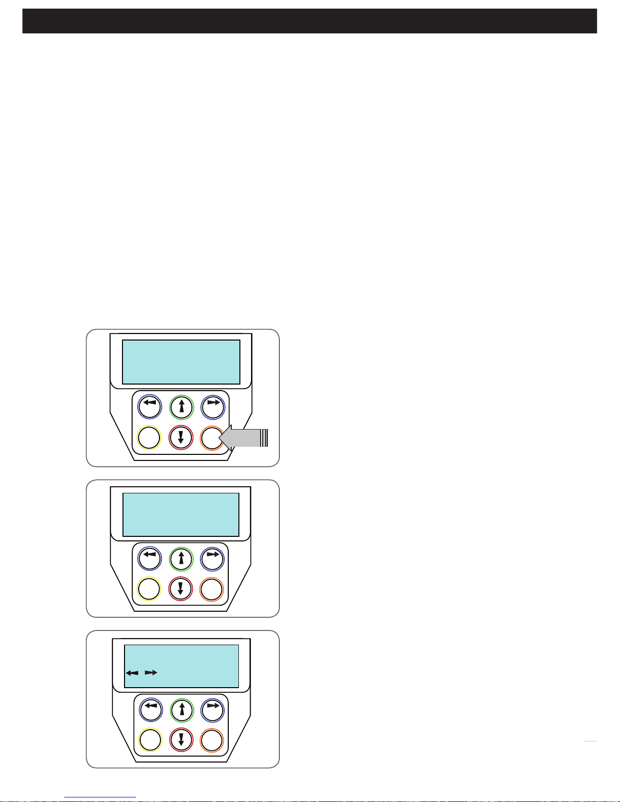
Parameter Min Max Default Menu Section
Menu 8 - Diagnostics
TEST INPUTS - Controls input display status Inactive 8.1 Appendix D
TEST TRANSMITTERS (TX’ERS) 8.2 Appendix D
DISPLAY HISTORY 8.3 Appendix D
MEMORY USAGE 8.4 Appendix D
SERVICE COUNTER 60,000 8.5 Appendix D
EVENT COUNTER 8.6 Appendix D
Menu 9 - Memory Tools
CLR CONTROL 9.1 Appendix E
CLR TRANSMITTERS (TX’ERS) 9.2 Appendix E
Menu 10 - Setup Travel
SETUP LIMITS 10.1 8.1
TIME TRAVELED 10.2 Appendix H
REPROFILE TRAVEL 10.3 9.5
SET PEDESTRIAN 10.4 12.1
Page 23

Owner Installation Instructions DCB-05V2 Gate Controller 23
The standard operation of the opener can be altered by editing various parameters. This section describes the parameters
and the effect they have. Use the VIEWING AND EDITING PARAMETER PROCEDURE (Appendix B) to make changes.
C - Control Board Adjustments
Appendix
Menu 6. Motor settings
Motor speed
The motor settings adjust various aspects of the gate travel.
When a single gate installation is used the SYNC DELAY
TIMES and M2 settings are ignored. The default value for
the CLOSE SYNC DELAY time is automatically calculated
for LIMIT SWITCH/AMP TRAVEL installations. The value
calculated is selected so that the delay between M2 and
M1 reaching the close position is equal to the OPEN SYNC
DELAY TIME. The MAX OVERRUN TIME is set to 0 for
TIMED TRAVEL installations.
Menu 7. Operating Modes
Menu 7.1 First (SB1) Safety Beam Type
Select what type of Safety Beam (2 WIRE or 3 WIRE). 2
WIRE is default.
Menu 7.2 Second (SB2) Safety Beam Type
Select what type of Safety Beam (2 WIRE or 3 WIRE). 2
WIRE is default.
Menu 7.3 First (SB1) Safety Beam Response Mode
The Safety Beams input can be configured to respond in
one of eight modes.
i. Not Used
ii. Close to Reverse In this mode, the Safety Beam
input has no effect when opening but will cause the
gate to reverse if activated when closing.
iii. Close to Stop In this mode, the Safety Beam input
has no effect when opening but will stop the gate
when closing.
iv. Open and Close to Stop In this mode, all cycles are
prevented from being completed or initiated when
the Safety Beam input is active.
v. Open input In this mode, open cycle is initiated
when the Safety Beam is activated.
vi. Swipe input In this mode, open cycle is initiated
when the Safety Beam is activated.
vii. Close input In this mode, close cycle is initiated
when the Safety Beam is activated.
viii. Ped input In this mode, ped cycle is initiated when
the Safety Beam is activated.
ix. Disabled In this mode, Safety Beam is disabled.
Menu 7.4 Second Safety Beam (SB2) Response Mode
Same as above menu 7.3
Menu 7.5 PED Input Function
If GPI or Fire Input is selected as PED then these inputs
can be configured to a SWIPE type input for pedestrian
access. This provides full functionality with the Safety Beam
Triggered Pedestrian Auto-Close function.
Menu 7.6 Open (Opn) Input
(Activated by OPN terminal with N/O switch, by transmitter
button with OPN function assigned or by console’s UP
button) Activating the OPN input will cause the gate to
open. Holding the input will prevent closing.
Menu 7.7 Stop (STP) Input
(Activated by STP terminal with N/O switch, by transmitter
button with STP function assigned or by console’s EXIT
button) Activating the STP input while the gate is moving
will cause the gate to be stopped. If the STP terminal is
held it will prevent the gate from being moved.
Menu 7.8 AUX Input
Is Default to Light, however can be changed to Motor
Engaged.
Menu 7.9 Vacation Mode
Vacation mode can be turned on or off using this parameter.
DCB-05V2 supports a Vacation mode where remote control
access is disabled. The mode is activated by pressing a
transmitter button with the VAC function assigned until the
console displays that vacation mode is enabled (approx.
5 seconds). When activated any transmitter button which
is assigned VAC will be ignored. To turn the Vacation
mode off, simple press a transmitter button with the
VAC function assigned (Only requires a brief activation).
Vacation mode can also be turned on or off manually by
editing the VACATION MODE parameter. DCB-05V2 can
be instructed, via the pedestrian control feature, to partly
open and provide pedestrian access but prevent vehicle
access. This is achieved by partly opening the motor 1
gate leaf. If dual motors are used, motor 2’s gate leaf is
held closed. The partly open position of motor 1’s gate
leaf is initially set to a position halfway between open and
closed. This initial position can be adjusted by the installer
to any position within the gates travel range by selecting
a pedestrian access travel time (from closed). The setting
is accessed from “MENU 10.4 Set Pedestrian”. The time is
adjustable in 1 second steps
Menu 7.10 Remote Code
The controller supports the Remote Code Set feature. This
parameter can be used to disable the feature for security or
transmitter management reasons.
Menu 7.11 Battery / Solar Mode
The controller can be instructed to turn off the Battery
Backup / Solar facilities so that the control board can be
shut down without having to disconnect the Battery Backup
/ Solar system.
Menu 7.12 Password Protection
The password feature enables all parameters and
configuration settings to be protected unless a password
is entered. When this feature is turned on, the user is
requested to enter the desired password to be used. The
password protection feature has a time-out that expires
after 60 seconds of inactivity. Alternatively, the user may
log out manually by pressing exit when the main screen is
displayed.
Menu 7.13 Transmitter Grouping
The transmitter store number display format can be
changed to show a grouped format. When grouping is
selected, instead of displaying the store location as a
number between 1 and 511, it will display as ##$ where ##
is the group number and $ is a character a,b,c,d,e,f,g or h
which indicates the group member.
Menu 7.14 Output1 Mode
AUX output can be selected to be driven by:
i. Lock Drive: Lock output can be programmed for both
hold and pulse mode. The operation of the lock can
be programmed to activate prior to the gate and
behave differently on open cycles to that on close
cycle.
ii. Light Drive: a light relay module can be connected on
the console between V+ and OUT2 terminal which will
turn the courtesy light on and off.
iii. 3 Wire Safety Beam 0V:
iv. Not Used
Page 24
24
DCB-05V2 Gate Controller Owner Installation Instructions
C - Control Board Adjustments
Appendix
The controller provides several diagnostic tools from within the
Diagnostics Menu (Menu 8). This section details the function of
each tool and its use.
Navigating To Diagnostics Menu
a. Press PREV to navigate to Menu 8 (Fig. D.1).
b. Press SET to display the menu of available functions.
c. Press PREV or NEXT to cycle through diagnostic tools.
d. Press SET to select.
Menu 8.1 Test Inputs
This tool is used to view the state of the control inputs. When
selected, a screen is displayed (Fig. D.2) which indicates the
state of each input. If the name of the input is in upper case or
number in the bracket, then the input is active. Conversely if the
input is in lower case and [---] dash in the bracket, then the input
is inactive. For normal operation, all inputs should be inactive.
When finished, press EXIT. The example shows the status as OSC
input is active.
Menu 8.2 Test Transmitters (Tx’ers)
This tool is used to test receiver/transmitter functionality. When
selected, a screen is displayed which prompts for a transmitter
button to be pressed (Fig. D.3) and whether ID or serial numbers
are to be displayed.
DCB-05V2 will then beep each time a transmission is received. If
the transmitter button is stored in the DCB-05V2’s memory and
has a function assigned to it, a second screen will be displayed
that shows the transmitter details along with the button pressed
(Fig. D.4). The example shows the case where transmitter number
12 is activated by button 4. Note ID is selected for display.
PREV NEXT
EXIT
SET
Diagnostics
MENU 8
PRESS
PREV NEXT
EXIT
SET
cls osc swp ped
I/P pe opn stp
PREV NEXT
EXIT
SET
/ Shows ID/SN
PRESS TX’ER
Fig D.1
Fig D.2
Fig D.3
D- Diagnostic Tools
Appendix
Menu 7.15 Output2 Mode
AUX output can be selected to be driven by:
i. Lock Drive: Lock output can be programmed for both hold and pulse mode. The operation of the lock can
be programmed to activate prior to the gate and behave differently on open cycles to that on close cycle.
ii. Light Drive: a light relay module can be connected on the console between V+ and OUT2 terminal which will
turn the courtesy light on and off.
iii. 3 Wire Safety Beam 0V:
iv. Not Used
Menu 7.16 Fault, Auto Reset
When selected, the controller will reset any fault automatically.
Menu 7.17 Safety Beam Failure Emergency Close Mode (SBFEC)
When a safety beam prevents movement due to any reason other than a ‘real’ obstruction, the user can secure their
property by pressing and holding a button on the remote control or OSC on the console. The button must be held active
for more than five seconds to activate this mode and hold the button for the entire duration of close cycle.
Page 25
Owner Installation Instructions DCB-05V2 Gate Controller 25
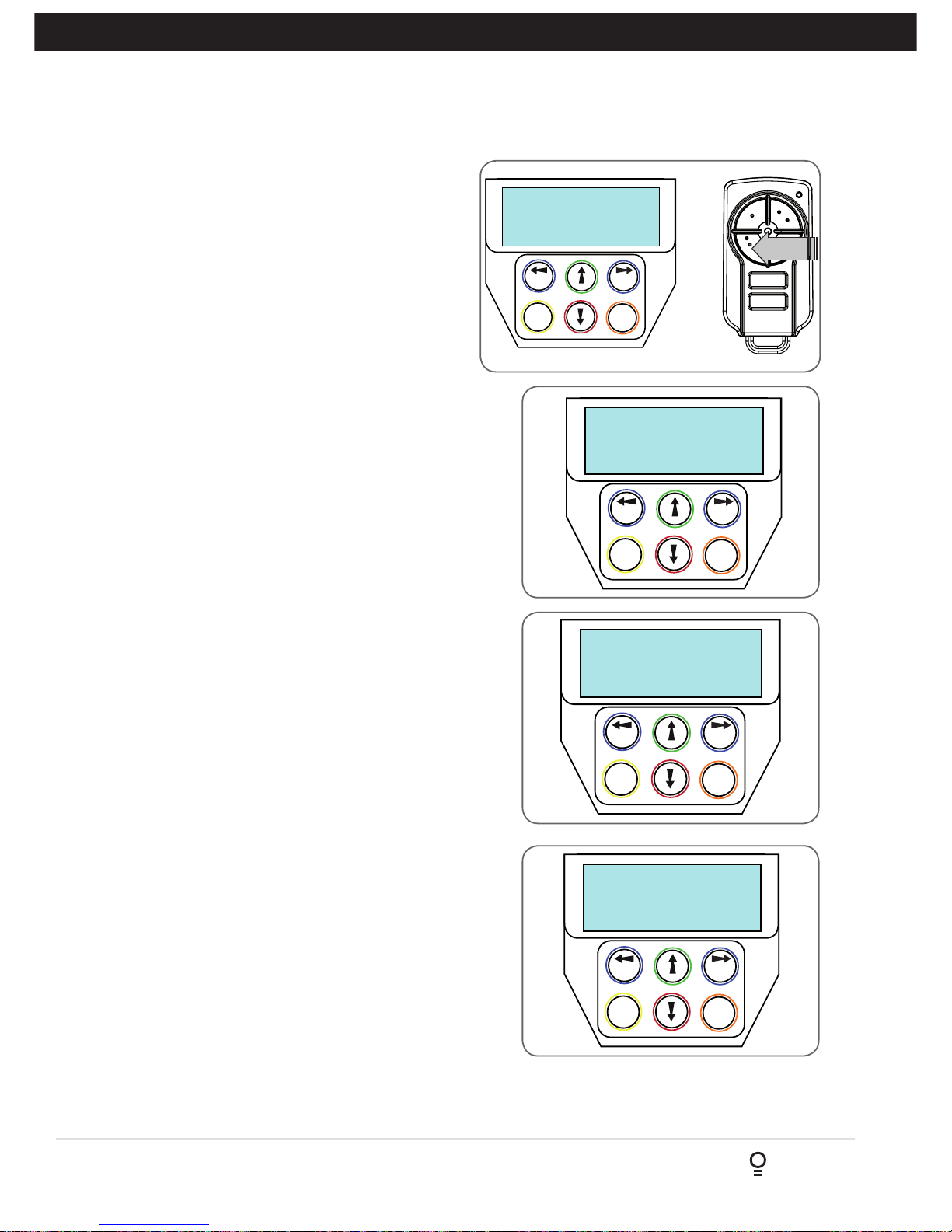
PREV NEXT
EXIT
SET
EVENT# 64
Close Complete
PREV NEXT
EXIT
SET
OSC PED LGT>VAC
124 ID B B SMITH
PRESS
Fig D.4
Fig D.5
Menu 8.3 Display History
DCB-05V2 keeps a record of the last 64 events that
have taken place. The events include the type of
drive cycles executed, obstruction detection, various
faults, power failures etc. When this tool is selected,
the screen displays the last event that occurred
(Fig. D.5). Press NEXT or PREV to view each event. The
“EVENT#” field shows the sequence of the events, with (1)
being the first and (64) being the last. The example shows
that the last event was a close cycle which succeeded in
closing the gate. When finished viewing the events, press
EXIT.
PREV NEXT
EXIT
SET
(CYCLES) 60000
Service Counter
PREV NEXT
EXIT
SET
1234
1:Open Cycles
Fig D.7
Fig D.8
D- Diagnostic Tools
Appendix
Menu 8.4 Memory Usage
This tool displays the number of transmitter store locations used
and the number free.
Menu 8.5 Service Counter
DCB-05V2 provides a periodic service counter which can be
set to expire after a number of drive cycles. When expired,
DCB-05V2 will beep at the beginning of each drive cycle
and a message will be displayed on the MAIN SCREEN
(Fig. D.7). This tool displays the current value of the service
counter and allows the user to set its value using the normal
parameter editing techniques (See PARAMETER VIEWING AND
EDITING). If the service counter is not to be used, it can be set
to the maximum number (60,000).
Menu 8.6 Event Counters
The opener keeps a count of number of times a particular event
occurs. The list of event counters kept is shown below. When this
tool is selected, the first event counter is shown (Fig. D.8). Press
NEXT or PREV to step through the list. The example shows the
OPEN CYCLE event counter with a value of 1234. When finished
viewing press EXIT.
1: Open Cycles 2: Close Cycles
3: PED Cycles 4: Warranty Cycles
5: Setup Limits 6: Overlaps
7: M1 Open Obstuctions 8 M2 Open Obstuctions
9: M1 Close Obstuctions 10: M2 Close Obstuctions
11: M1 Open Overloads 12: M2 Open Overloads
13: M1 Close Overloads 14: M2 Close Overloads
15: M1 Volts Faults 16: M2 Volts Faults
17: M1 AMP Faults 18: M2 AMP Faults
19: Supply High Faults 20: Supply Low Faults
21: M1 AMP Trip 22: M2 AMP Trip
23: 3W Limit Faults
Page 26
26
DCB-05V2 Gate Controller Owner Installation Instructions
The Memory Tools accessed from within Menu 9 are used to backup, restore or clear the controller. Once selected, the
PREV or NEXT buttons can be used to view the Memory Tool options. To Execute the displayed option simply press SET.
Menu 9.1 Clear Control
This option will clear the gate control memory and reload the factory set defaults for parameters such as the lock time,
light time, auto-close times etc. It will also clear the travel limits.
Menu 9.2 Clear Transmitters (Tx’ers)
This option will clear the transmitter storage memory.
E - Memory Tools
Appendix
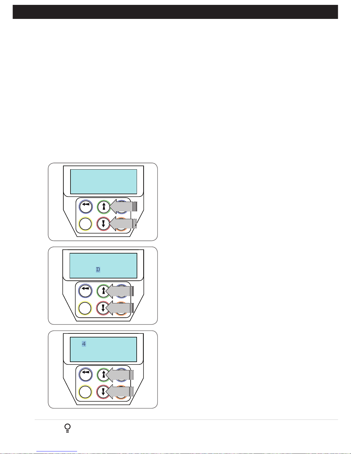
Navigating To “Edit Transmitter” Menu
a. Press NEXT to navigate to Menu 1.
b. Press SET to enter the transmitter edit procedure.
c. Press NEXT to enter transmitter list and edit mode.
Editing Button Function Field
a. Press NEXT or PREV to move the cursor to the left or right and
between the top and bottom lines to select the desired field.
b. Press UP or DOWN arrows to change the displayed value
(Fig. F.1). The available functions are shown below. Selecting
OFF will prevent the opener responding to that button.
Available functions
VAC (Vacation Mode) LGT (Courtesy Light)
STP (Stop) OPN (Open)
CLS (Close) SWP (Swipe)
PED (Pedestrian access) OSC (Open/Stop/Close)
OFF (No action)
c. Press SET to save changes or press NEXT or PREV to move to the
next field. The example in (Fig. F.2) shows that PED is assigned
to the transmitter button 2. The transmitter in the example is
transmitter number 123 which has the ID label AB Smith.
NOTE: If all button functions are set to OFF, when SET is pressed,
the opener will prompt to confirm if the transmitter is to be deleted.
Press SET to delete or EXIT to continue editing.
Editing The Store Location
This feature is only available when coding the first button of a new
transmitter.
a. Press NEXT or PREV to move the cursor over Store No. (Fig. F.3)
b. Press UP or DOWN arrows to select new Store No.
c. Press SET to Confirm or NEXT/PREV to move to the next field.
This is useful when managing transmitters using a scheme which
ties the store location to the transmitter’s owner.
MENU 1
PREV NEXT
EXIT
SET
Code Transmitter
PRESS
PRESS
PREV NEXT
EXIT
SET
OSC PED LGT VAC
123 ID A B SMITH
PRESS
PRESS
PREV NEXT
EXIT
SET
OSC PED LGT VAC
124 ID A B SMITH
PRESS
PRESS
Fig F.1
Fig F.2
Fig F.3
F- Transmitter Editing
Appendix
Page 27
Owner Installation Instructions DCB-05V2 Gate Controller 27
Fig F.4
PREV NEXT
EXIT
SET
OSC PED LGT VAC
124 SN123456789
PRESS
PREV NEXT
EXIT
SET
56789 ABCDEFGHIJ
124 ID B B SMITH
Fig F.5
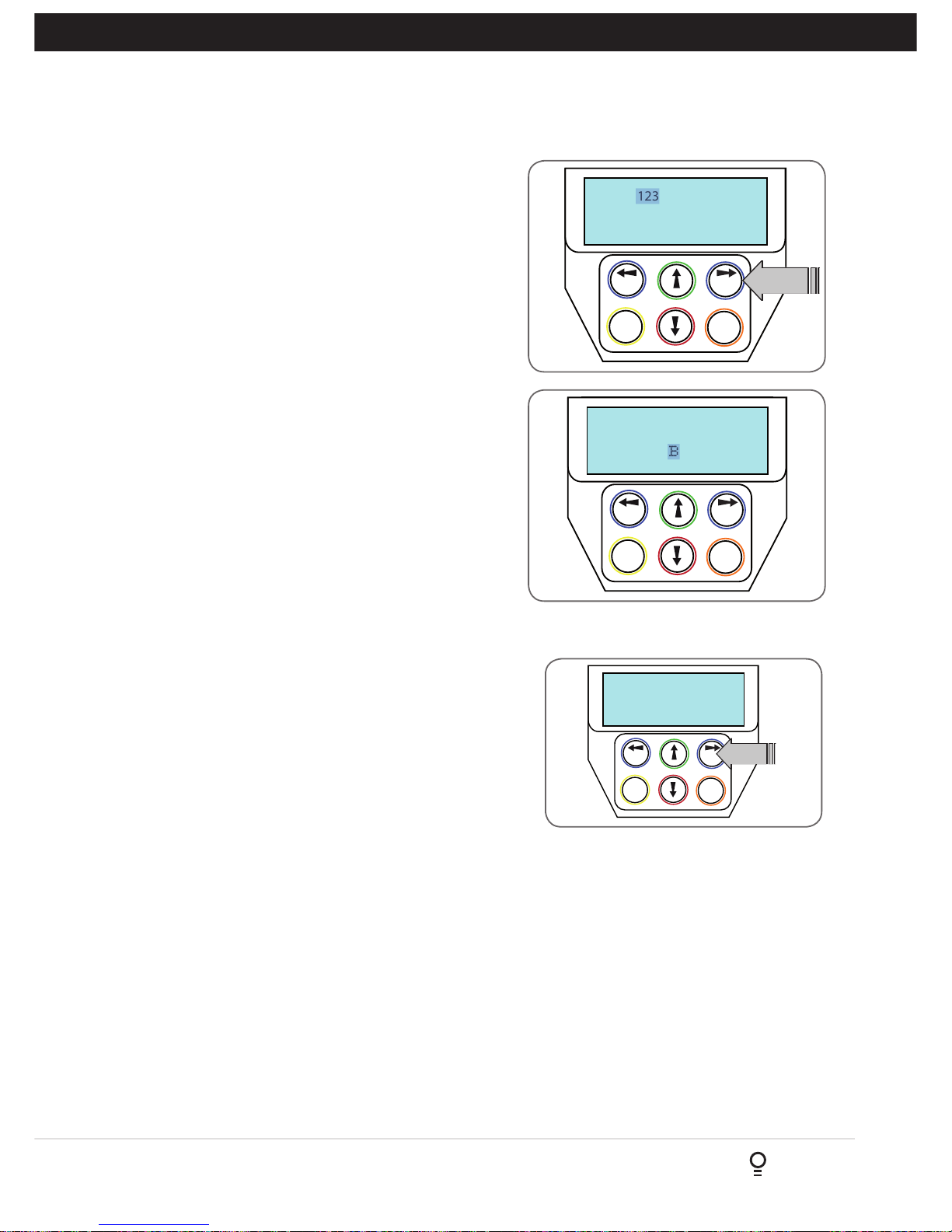
Selection Of ID or Serial Number Display
a. Press NEXT to navigate to the Menu 1 ”Code Transmitter”.
b. Press SET to enter the transmitter edit procedure.
c. Press NEXT to enter transmitter list and edit mode.
d. Press NEXT/PREV to move the cursor over the ID field.
e. Press NEXT to reveal the Serial Number (Fig. F.4).
The serial number display is provided for additional means of
identification. The transmitter in this example has serial number
123456789.
Editing A Character Field
a. Press NEXT or PREV to move select character.
b. Press UP or DOWN arrows to scroll through and select a new
character. (Fig. F.5)
c. Press NEXT or PREV to move to the next character.
d. Repeat step b.
e. Press SET to record changes.
The second line of the display shows a list of available characters
with the current value indicated at the cursor position.
F- Transmitter Editing
Appendix
G- Transmitter Managment
Appendix
Transmitter Listing Facility
DCB-05V2 provides a transmitter listing facility which enables the user
to find a transmitter location within memory. Once located a stored
transmitter can be replaced, deleted, edited, copied or, if the location
is empty, a new transmitter can be coded.
Method 1 - Go To The Start Of The List
Accessing The List Menu
a. Press NEXT to navigate to Menu 1.
a. Press SET to enter the transmitter edit procedure.
b. Press NEXT to enter the transmitter list and edit mode.
Fig G.1
PREV NEXT
EXIT
SET
Button! LIST>
Press Tx’er
PRESS
Method 2 - Use The Transmitter To Go Direct To The List
Accessing The List Menu
c. Press NEXT to navigate to Menu 1.
d. Press SET to enter the transmitter edit procedure.
e. Press the transmitter once.
f. Press NEXT to view the transmitter parameters (Fig. G.1). This method
is used for quick navigation if the transmitter is available.
NOTE: “VIEW” will not be shown if the
transmitter is not stored. Once the list
is displayed, it can be sorted by stored
number, ID Label or Serial Number. Use
the NEXT or PREV buttons to select the
sorting method.
NOTE: When sorting by ID label or S/N,
only stored transmitters locations are
displayed.
Navigating The List
a. Press the UP or DOWN arrows to navigate through the list.
NOTE: Holding a button down will step through the list faster.
b. Press SET to display the menu of available functions.
Selecting An Operation
a. Press NEXT or PREV to cycle through the four menu options (Fig G.2 over page)
b. Press EXIT to return to the list.
c. Press SET to execute the menu’s operation.
Page 28
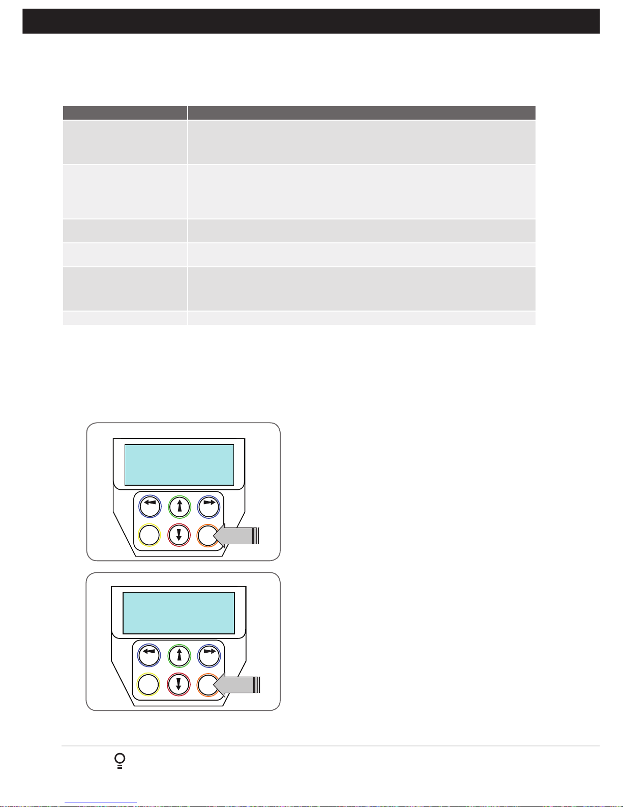
28
DCB-05V2 Gate Controller Owner Installation Instructions
Fig G.2
Menu Option
Operation
Code Operation (location
empty)
If the code operation is selected on an empty transmitter location, the BASIC CODE
TRANSMITTER PROCEDURE will be initiated with the transmitter being saved in the selected
location. This is useful when managing transmitters using a scheme which ties the store
location to the transmitter’s owner.
Code Operation (location used) If the code operation is selected for a location that already contains a transmitter, then the
BASIC CODE TRANSMITTER PROCEDURE will be initiated and the new transmitter will
replace the existing one. Note that the button functions and name of the existing transmitter
will be transferred to the new transmitter. This procedure is of great convenience when
replacing a lost transmitter.
Delete Operation The delete operation is used to remove a transmitter from memory along with the name and
button function settings.
Edit Operation The edit operation displays the transmitter record for editing purposes. See TRANSMITTER
EDIT PROCEDURE (Appendix F) for details.
Copy Operation The copy operation is used to code multiple transmitters with the same button function as that of
the selected transmitter. Once selected an abbreviated code set routine is initiated which repeats
steps 2 & 3 of the BASIC CODE TRANSMITTER PROCEDURE for each transmitter to be coded.
Coding is terminated by pressing the EXIT button.
Exiting The List
To exit the transmitter list, simply press EXIT to return to the Code menu.
PLEASE NOTE, THE FOLLOWING INSTALLATIONS ARE FOR 2
WIRE SETUPS ONLY
Selecting The Number Of Motors
a. Press NEXT to navigate to Menu 10.1.
b. The DCB-05V2 will now prompt for the number of motors
connected to be entered.
c. Use the UP or DOWN arrows to select the correct number and
then press SET (Fig. H.1).
d. Press EXIT.
Navigating To “Limit/AMP Travel Menu”
a. Press NEXT to navigate to Menu 10.
b. Presee SET to locate Menu 10.1.
c. Press SET again to start the limit setting procedure .
d. DCB-05V2 will prompt you to confirm that the motor wiring
is complete (Fig. H.2) and that the gate(s) are at fully open
position and engaged.
e. Press SET to confirm.
f. DCB-05V2 will now automatically detect the type of drive unit
used by the number of wires used. If the correct number of wires
is displayed then press SET to continue otherwise press EXIT
and check the wiring.
g. DCB-05V2 will now automatically detect if one or two motor are
connected. If the correct number is displayed then press SET to
confirm. Otherwise press EXIT and check the wiring (Fig. H.3).
Fig H.1
Fig H.2
H- AMP Travel (2 Wires Setup)
Appendix
MENU 10.1
Limit/AMP Travel
PREV NEXT
EXIT
SET
PRESS
Selecting Limit/AMP Travel Setup
Motor Wiring
PREV NEXT
EXIT
SET
Completed ?
PRESS
Confirming Wiring is Completed
G- Transmitter Managment
Appendix
Page 29
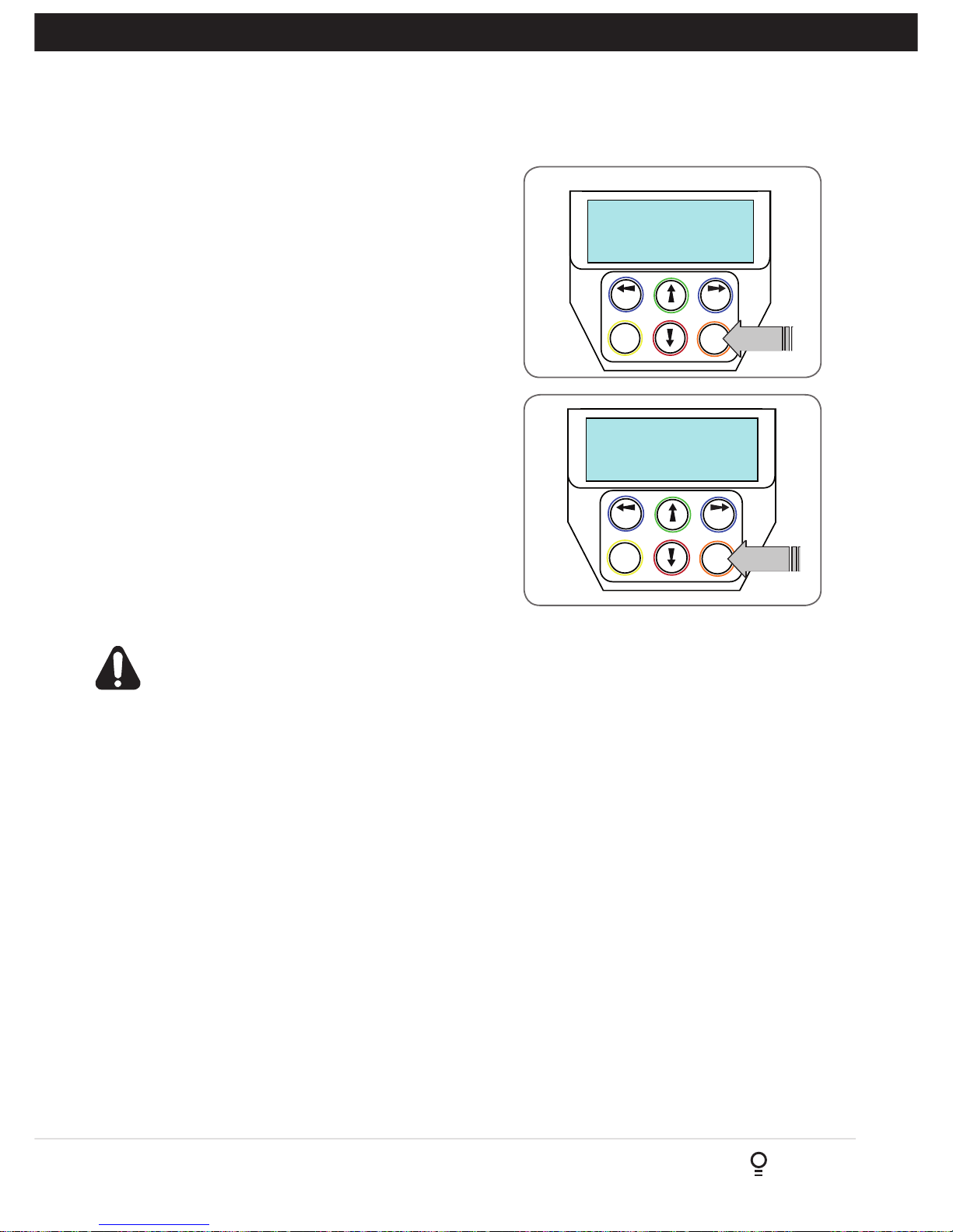
Owner Installation Instructions DCB-05V2 Gate Controller 29
M1&2 Detected
PREV NEXT
EXIT
SET
Press Set If OK
PRESS
Fig H.3
Fig H.4
Is Gate Open?
PREV NEXT
EXIT
SET
PRESS
Confirming Detected Motor Wiring
Test and Adjust Stop Detection
For this type of installation the DCB-05V2 detects the travel limits
by sensing a motor current trip when the mechanical stop is
reached.
NOTE: If a dual gate installation is being used, complete steps for
motor 2 and then motor 1.
a. To Setup Limits follow the instructions on the LCD display.
b. Open the gates fully and engage the motors.
c. Using the UP and DOWN arrows drive the gate using one
continuous movement stopping just before the mechanical
stop.
NOTE: If the motor drives in the wrong direction (UP closes gate
/ DOWN opens gate) the motor wires need to be swapped over.
Confirming Settings
When the settings have being adjusted correctly, drive the gate to
the open stop.
a. Press the SET Key
b. In order to run automatic profiling the DCB-05V2 will prompt
you to confirm the gate leaf is in the open position.
c. Press SET to confirm or press EXIT to go back and drive the
gate open (Fig. H.4).
Automatic Profiling
After a brief pause DCB-05V2 will automatically close and open gate
several times and learn the gates load and travel characteristics.
WARNING: The gate will automatically close and
open. Ensure that no persons or objects are in the
gates path.
When the setup is complete the MAIN SCREEN will be displayed
with the gate shown to be OPEN.
The Gate can now be used.
Reprofiling Travel
a. Reprofiling is a simplified way of re-learning the travel
characteristic of a previously setup Limit Switch travel installation.
Re-profiling can be used when the travel characteristics of the
gate(s) change due to mechanical adjustments etc. To initiate
a re-profile, simply locate “MENU 10.3 Reprofile Travel”, press
SET and follow the prompts. The gate(s) will start to move and
re-calculate force margins. The gate(s) can move between the
open and close limit positions up to two (2) times (depending
on the position of the gate(s) and the power up condition).
b. A single beep will be heard once the process is complete.
c. Test the force again as per “Safety Obstruction Force Test”
(Section 9.1 and 9.2)..
H- AMP Travel (2 Wires Setup)
Appendix
Page 30
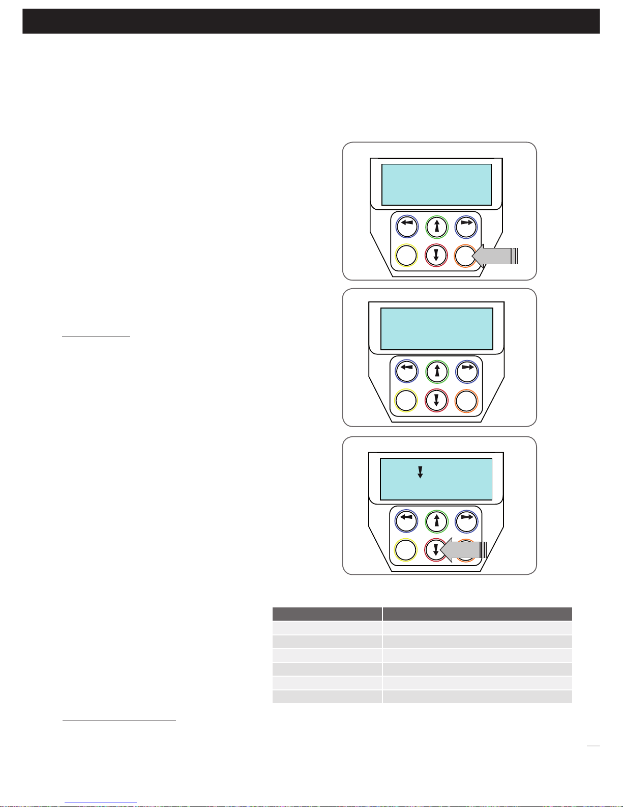
30
DCB-05V2 Gate Controller Owner Installation Instructions
Hold To Set
PREV NEXT
EXIT
SET
Close Cycle Time
PRESS
This section shows how to set the travel times when using drive units with slip clutches etc. Two methods are available for
setting up the travel times. The first allows the installer to drive the motor(s) so that the actual travel time can be recorded.
The second allows exact times to be entered.
Current Trips
PREV NEXT
EXIT
SET
Are Disabled OK?
PRESS
Confirming Obstruction detection is disabled
I - Time Travel 2 Wire Setup
Appendix
Fig I.1
Fig I.2
SET=Drive Motors
PREV NEXT
EXIT
SET
EXIT=Enter times
Selecting install method
Setting close cycle time
Fig I.3
Fig I.4
Parameter Description
M1 Normal Open Time Sets Open drive time for M1
M1 Normal Close Time Sets Close drive time for M1
* M2 Normal Open Time Sets Open drive time for M2
* M2 Normal Close Time Sets Close drive time for M2
* Close Sync Delay Sets Delay before M1 is started on closed cycles
* Open Sync Delay Sets Delay before M2 is started on open cycle
* Only used for dual gate installations. Once the parameter values have be set
press EXIT and the main screen is displayed, the gate is ready for use.
NOTE: The limit setting procedure can be aborted at any time by
pressing EXIT.
Navigating To “Timed Travel Menu”
a. Press NEXT to navigate to Menu 10.
b. Presee SET to locate Menu 10.2.
c. Press SET again to start the the setup.
d. Confirm that the motor wiring is complete. Press SET to continue.
e. No current trip obstruction detection is available when using timed
travel. Press SET if you accept this (Fig. I.1).
f. Enter the number or motors by using the UP or DOWN key to
select the correct number and then press SET.
Selecting Setup Method
a. DCB-05V2 will now prompt for the setup procedure to be selected.
There are 2 methods (Fig. I.2);
i. DRIVE MOTORS = Press SET to continue
ii. ENTER TIME PARAMETERS = Press EXIT to continue
DRIVE MOTORS
Adjusting Gate Leaf Synchronising Delays.
(Dual gate installations only)
DCB-05V2 will prompt for you to edit the gate leaf synchronising
delays. The settings are used to introduce a delay between when
the motors start so that overlapping gates are opened and closed in
the correct order.
a. Press SET to access the gate leaf synchronising delay parameters
b. Follow LCD display to edit delay.
Confirming Gate Is Open
DCB-05 will now prompt for you to confirm that the gate is open.
a. If the gate is open press SET and continue.
b. If the gate is closed Press EXIT and DCB-05 will now prompt for
the gate to be opened.
i. Press and Hold the UP key until the gate is open. When the UP
key is released the motor(s) will stop and you will be asked if
the gate is open.
NOTE: If the motor drives in the wrong direction the motor wiring
needs to be swapped.
Setting Close Cycle Drive Time
To set the close cycle drive time press and hold the DOWN key until
the gate is driven fully closed. (Fig I.3)
NOTE: If the motor drives in the wrong direction the motor wiring
needs to be swapped.
Setting Open Cycle Drive Time
To set the open cycle drive time press and hold the
UP key until the gate is driven fully open.
Confirming Settings
Press SET to confirm or EXIT to restart from
Confirming gate is open.
Once the setting have been SET and the main
screen is displayed, the gate is ready for use.
ENTER TIME PARAMETERS
When the ENTER TIMES method is selected a list
of parameters is provided to configure the gates
travel. The parameters provided are listed below
in Fig I.4 with a brief description.
Page 31

Owner Installation Instructions DCB-05V2 Gate Controller 31
20. Warranty and Exclusion of Liability
1. This Warranty is given by Dominator on behalf of Automatic
T
echnology (Australia) Pty Ltd (ABN 11 007 125 368) (ATA), Ph: 0800
366 462, [email protected]
2. The Competition and Consumer Act 2010 (including the New
Zealand Consumer Law) and other relevant statutes provide a set of
statutory consumer guarantees and other legal rights that cannot be
excluded, restricted or modified by contract. This Warranty is in addition
to and does not affect any of your rights under the New Zealand
Consumer Law and other relevant statutes.
3. Our goods come with guarantees that cannot be excluded under the
New Zealand Consumer Law. You are entitled to a replacement or refund
for a major failure and for compensation of any other reasonably
foreseeable loss or damage. You are also entitled to have the goods
repaired or replaced if the goods fail to be of acceptable quality and the
failure does not amount to a major failure.
4.
5.
(a)
Subject to your non-excludable rights under the New Zealand Consumer
L
aw, ATA expressly excludes any liability for consequential loss,
incidental or indirect damages (including but not limited to damages for
loss of business profits, business interruption and loss of business
information) due to a defect of the DCB-05V2 Control System (Product).
In particular any loss or damage caused to other equipment or accessories
used with the product or any loss resulting from a delay in repair is
excluded to extent permitted by law.
Subject to all of the matters set out below, ATA warrants in relation to the
Product that:
the Product’s drive units will be free of any defects in material and
workmanship for at least 24 months after the date of purchase (as evidenced
by the sales docket receipt),or 5000 cycles, which ever occurs firts and
(b) the Product’s other components and accessories will be free of any defects
in material and workmanship for at least 12 months after the date of
purchase (as evidenced by the sales docket receipt).
6. No additional warranty will apply for Products repaired during the relevant
warranty period.
7. For all Products repaired outside the warranty period, a six (6) month warranty
that the Product will be free of any defects in material and workmanship will
apply from the date of dispatch of the Product to you. ATA may charge
you for any repairs undertaken outside the warranty period, and will provide
you with a quotation in relation to any such costs for your approval before
proceeding with any repairs.
8. This Warranty applies only where you:
(a) immediately notify ATA at the contact details provided in paragraph 1
above or notify the or the retailer that you purchased the Product from of
the alleged defect;
(b) return the product to the retailer that you purchased the Product from; and
(c) present the relevant sales docket and this Warranty document to the retailer
to confirm the date of purchase.
9. Except for this Warranty, ATA gives no warranties of any kind whatsoever
(whether express or implied), in relation to the product, and, subject to
paragraph 1 above, all warranties of whatsoever kind relating to the product
are hereby excluded.
10. This Warranty excludes damage resulting from:
(a) normal wear and tear;
(b) accidental damage;
(c) incorrect installation of the Product;
(d) blown fuses, electrical surges, power surges or power spikes;
(e) theft, fire, flood, rain, water, lightning, storms or any other acts of God;
(f) any installation, configuration or use of the Product contrary to the
instructions supplied with the Product;
(g) the gate used with the Product not being in safe working order and
condition;
(h) repairs which are not authorised by ATA;
(i) any failure to install or maintain the Product in accordance with the
instructions supplied with the Product;
(j) any use which is not in accordance with the instructions provided with the
Product;
(k) deliberate or negligent damage to the Product;
(l) any unauthorised modification to the Product;
(m)faulty or unsuitable wiring in the building in which the Product is installed;
(n) damage caused by insects;
(o) any cost or expense relating to the recall of the Product;
(p) installation of a residential gate opener in a commercial or industrial
situation or in a dwelling other than a single-family dwelling;
(q) radio or electrical interference; or
(r) acts or omissions of any person (including service providers approved by
ATA) other than ATA.
11. ATA’s liability under this Warranty is limited, at ATA’s absolute option, to
replacing or repairing the product which ATA, in its unfettered opinion,
considers to be defective either in material and/or workmanship or to credit
the dealer with the price at which the product was purchased by the dealer.
12. This Warranty does not extend to cover labour for installation of the Product
following repairs, the cost of which must be borne by you.
13. This Warranty is limited to Return-to-Base (RTB) repair and does not cover
labour for on-site attendance, the cost of which must be borne by you.
14. Except as specified in this Warranty, ATA will not charge you for any repairs
or replacements conducted under the Warranty. However, ATA will charge
you for any repairs which are not within the scope of this Warranty (or which
are not required to be undertaken free of charge pursuant to the Australian
Consumer Law).
15. This Warranty is void if the Product is not returned to the manufacturer in
original or suitably secure packaging.
16. This Warranty is only applicable for repairs to the product carried out within
Australia.
17. This Warranty does not cover consumable items including, without
limitation, globes, batteries and fuses.
18. This Warranty is not transferable.
19. Where the Product is retailed by any person other than ATA, except for the
warranty set out above, such person has no authority from ATA to give any
warranty or guarantee on ATA’s behalf in addition to the warranty set out
above.
20. Any provision of this Warranty that is prohibited or unenforceable in any
jurisdiction is ineffective as to that jurisdiction to the extent of the prohibition
or unenforceability. That does not invalidate the remaining provisions of this
Warranty nor affect the validity or enforceability of that provision in any other
jurisdiction.
21. Products presented for repair may be replaced by refurbished goods of the
same type rather than being repaired. Refurbished parts may be used to
repair the Product.
NOTES:
1. One (1) cycle = one (1) open and one (1) close action of the door or gate.
2. This Warranty is to be read in conjunction with the owner’s copy of the
installation instruction manual.
Page 32
32
DCB-05V2 Gate Controller Owner Installation Instructions
© June 2015 Automatic Technology (Australia)
Pty Ltd. All rights reserved. TrioCode™128
is a trademark of Automatic Technology
(Australia) Pty Ltd. No part of this document
may be reproduced without prior permission.
In an ongoing commitment to product quality
we reser ve the right to change specification
without notice. E&OE.
Supplied by: Dominator Garage Doors
P: 0800 366 462 E: info@dominator.co.nz
www.dominator.co.nz
 Loading...