

Page 1
OPERATION MANUAL
This manual does not include all of the details of design, production, or variations of the equipment. Nor does it cover every possible
situation which may arise during installation, operation or maintenance.
The information provided in this manual was deemed accurate as of the publication date. However, updates to this information may
have occurred. To obtain the latest version of this manual, please visit the AT website at www.atprofessional.com.au.
M2000
dB
0
8
-
dB
0
8
-
I
O
PROTECT
CLIP
SIGNAL
ACTIVE
PROTECT
CLIP
SIGNAL
ACTIVE
POWERCH A CH B
M2000
Page 2
M SeriesPower Amplifiers
page 2 Operation Manual
1) Read these instructions.
2) Keep these instructions.
3) Heed all warnings.
4) Follow all instructions.
5) Do not use this apparatus near water.
6) Clean only with a dry cloth.
7) Do not block any ventilation openings. Install
in accordance with the manufacturer s instr uctions.
8) Do not install near any heat sources such as
radiators, heat registers, stoves, or other
apparatus that produce heat.
9) Do not defeat the safety purpose of the polari zed or grounding-type plug. A polarized plug
has two blades with one wider than the other.
A grounding-type plug has two blades and a
third grounding prong. The wide blade or the
third prong is provided for your safety. If the
provided plug does not fit into your outlet,
consult an electrician for replacement of the
obsolete outlet.
10) Protect the power cord from being walked on
or pinched, particularly at plugs, convenience
receptacles, and the point where they exit from
the apparatus.
11) Only use attachments/accessories specified
by the manufacturer.
12) Use only with a cart, stand, bracket, or table
specified by the manufacturer, or sold with the
apparatus. When a cart is used, use caution
when moving the cart/apparatus combination
to avoid injury from tip-over.
13) Unplug this apparatus during lightning storms
or when unused for long periods of time.
14) Refer all servicing to qualified service perso nnel.Servicing is required when the apparatus
has been damaged in any way, such as power supply cord or plug is damaged, liquid has
been spilled or objects have fallen into the
apparatus, the apparatus has been exposed to
rain or moisture, does not operate normally,
or has been dropped.
15) To reduce the risk of fire or electric shock, do
not expose this apparatus to rain or moisture.
TO PREVENT ELECTRIC SHOCK DO NOT REMOVE TOP OR BOTTOM COVERS. NO USER SERVICEABLE PARTS INSIDE. REFER SERVICING
TO QUALIFIED SERVICE PERSONNEL.
MAGNETIC FIELD
CAUTION! Do not locate sensitive highgain equipment such as
preamplifiers or tape decks dirctly above or below the unit. Because this amplifier has a high power density, it has a strong
magnetic field which can induce hum into unshielded devices
that are located nearby. The field is strongest just aboveand below the unit.
If an equipment rack is used, we recommend locating the amplifier(s) in the bottom of the rack and the preamplifier or other
sensitive equipment at the top.
WATCH FOR THESE SYMBOLS:
The exclamation point triangle is used to alert theuser to important operating or maintenance instructions.
The lightning bolt triangle is used to alert the user to the risk of
electric shock.
Important Safety Instructions
Page 3

M Series Power Amplifiers
Operation Manual page 3
CE Declaration of Conformity
Equipment Type: Audio Power Amplifiers
Model Names: M2000
This product has been assessed against the following applicable Standards,
EMC (89/336/EEC Electromagnetic compatibility):
EN55013:2001 Sound and television broadcast receivers and associated equipment - Radio disturbance characteristics - Limits and methods of measurement
EN 55020:2002 Sound and television broadcast receivers and associated equipment - Immunity characteristics - Limits and methods of measurement
EN 61000-3-2:2000
Part 3-2: Limits - Limits for harmonic current emissions (equipment input current up to and including 16 A per phase)
EN 61000-3-3:1995
Part 3-3: Limits - Limitation of voltage changes, voltage fluctuations and flicker in public low-voltage supply systems, for equipment with rated current 16 A per
phase and not subject to conditional connection
LVD (73/23/EEC Low Voltage Directive)
EN60065:2002 Audio, Video and similar electronic-safety requirements.
Page 4

page 4 Operation Manual
Table of Contents
Important Safety Instructions .......................................................2
Declaration of Conformity ............................................................3
1 Welcome .................................................................................5
1.1 Features ...............................................................................5
1.2 How to Use This Manual ..........................................................5
2 Setup ......................................................................................6
2.1 Unpack Your Amplifier ............................................................6
2.2 Install Your Amplifier .............................................................6
2.3 Ensure Proper Cooling ............................................................6
2.4 Choose Input Wire and Connectors ...........................................7
2.5 Choose Output Wire and Connectors .........................................7
2.6 Wire Your System ...................................................................8
2.6.1 Stereo Mode .......................................................................8
2.6.2 Parallel Mode.....................................................................9
2.6.3 Bridge-Mono Mode ...........................................................10
2.6.4 Low Cut Mode.....................................................................10
2.6.5 Low Pass Mode..................................................................10
2.6.6 limiter Mode..................................................................10
2.7 Connect to AC Mains .............................................................11
2.8 Startup Procedure ................................................................11
3 Operation ..............................................................................12
3.1 Precautions ........................................................................ 12
3.2 Front Panel Controls and Indicators ...................................... 13
3.3 Back Panel Controls and Connectors...................................... 13
4 Advanced Features and Options ...............................................14
4 Advanced Features and Options ...............................................15
M SeriesPower Amplifiers
Page 5
1 Welcome
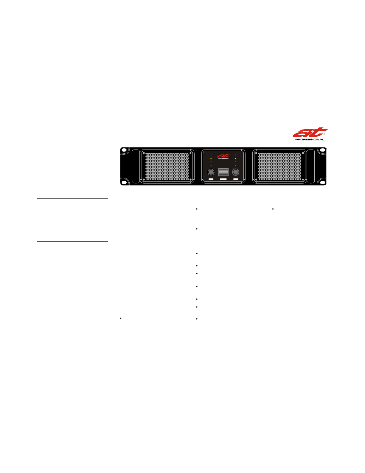
The M Series of power amplifiers from AT
audio represents a new era in affordable,
quality power amplification. The line consists of three models in a uniform, rugged
chassis, incorporating the best of tried-and
-true design principles and innovative features.
Modern power amplifiers are sophisticated
pieces of engineering capable of producing
extremely high power levels. They must be
treated with respect and correctly installed
if they are to provide the many years of reliable service for which they were designed.
In addition, M Series amplifiers include a
number of features which require some explanation before they can be used to their
maximum advantage.
Please take the time to study this manual
so that you can obtain the best possible service from your amplifier.
Operation Manual page 5
1.1 Features
Accurate, uncolored sound with very low
distortion for the best in music and voice
reproduction.
Bridge-mono/stereo mode switch allows
your amplifiers/speakers to be set up in
the configuration that best suits your
needs.
Advanced protection circuitry guards against shorted outputs, open circuits,
DC, mismatched loads, general overheating, high-frequency overloads and Internal faults.
Extremely versatile, handling a wide range of speaker impedances and outputs.
Features Limit Switch
Low Cut by 24dB/Octave Linkwitz-Riley
Filter
Low Pass by 24dB/Octave Linkwitz-Riley
Filter
Switchable input sensitivity.
Proportional speed fan optimizes cooling efficiency.
Can be mounted in EIA standard
or stacked on top of each other.
19-in.
Rack,
Features both standard 5-way binding
posts and genuine Speakon output connectors. XLR inputs.
1.2 How to Use This Manual
This manual provides you with the necessary information to safely and correctly setup
and operate your amplifier. It does not cover
every aspect of installation, setup or operation that might occur under every condition.
We strongly recommend you read all instructions, warnings and cautions contained
in this manual.
4-ohm Stereo 1600W
8-ohm Stereo 1000W
8-ohm Bridge-Mono 3000W
*1KHz Power:refers to maximum average power in
watts at 1KHz with 1.0% THD.
M2000
M Series Power Amplifiers
dB
0
8
-
dB
0
8
-
I
O
PROTECT
CLIP
SIGNAL
ACTIVE
PROTECT
CLIP
SIGNAL
ACTIVE
POWERCH A CH B
M2000
Page 6
page 6 Operation Manual
2 Setup
2.1 Unpack Your Amplifier
Please unpack and inspect your amplifier for any damage
that may have occurred during transit. If damage is found,
notify the transportation company immediately.. Save the
shipping carton as evidence of damage for the shipper s
inspection.
We also recommend that you save all packing materials so
you will have them if you ever need to transport the unit.
Never ship the unit without the factory pack.
YOU WILL NEED (not supplied):
Output wiring cables
Input wiring cables
Rack for mounting amplifier (or a stable surface for
stacking)
WARNING: Before you start to set up your
amplifier, make sure you read and observe
the Important Safety Instructions found at
the beginning of this manual.
2.2 Install Your Amplifier
CAUTION: Before you begin, make sureyour amplifier is disconnected from the power source, with
the power switch in the off position and all
level controls turned completely down (counterclockwise).
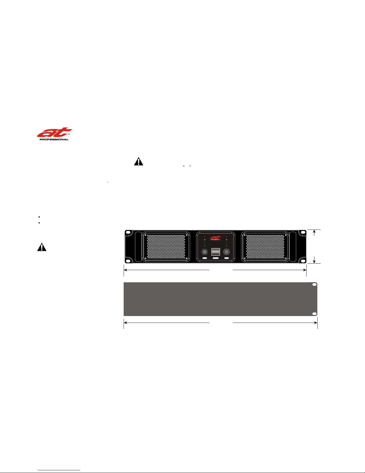
Use a standard equipment rack (EIA RS310B). See Figure 2.1 for amplifier dimensions.
19-inch (48.3 cm)
You may also stack amps without using a cabinet.
NOTE: When transporting, amplifiers should be supported
at both front and back.
2.3 Ensure Proper Cooling
When using an equipment rack, mount units directly on top
of each other. Close any open spaces in rack with blank panels. DO NOT block front, rear or side air vents. The side walls of the rack should be a minimum of two inches (5.1 cm)
away from the amplifier sides, and the back of the rack should be a minimum of four inches (10.2 cm) from the amplifier back panel.
Figure 2.1
Dimensions
483.0 mm
462.0 mm
88.0 mm
M SeriesPower Amplifiers
dB
0
8
-
dB
0
8
-
I
O
PROTECT
CLIP
SIGNAL
ACTIVE
PROTECT
CLIP
SIGNAL
ACTIVE
POWERCH A CH B
M2000
Page 7
Operation Manual page 7
2 Setup
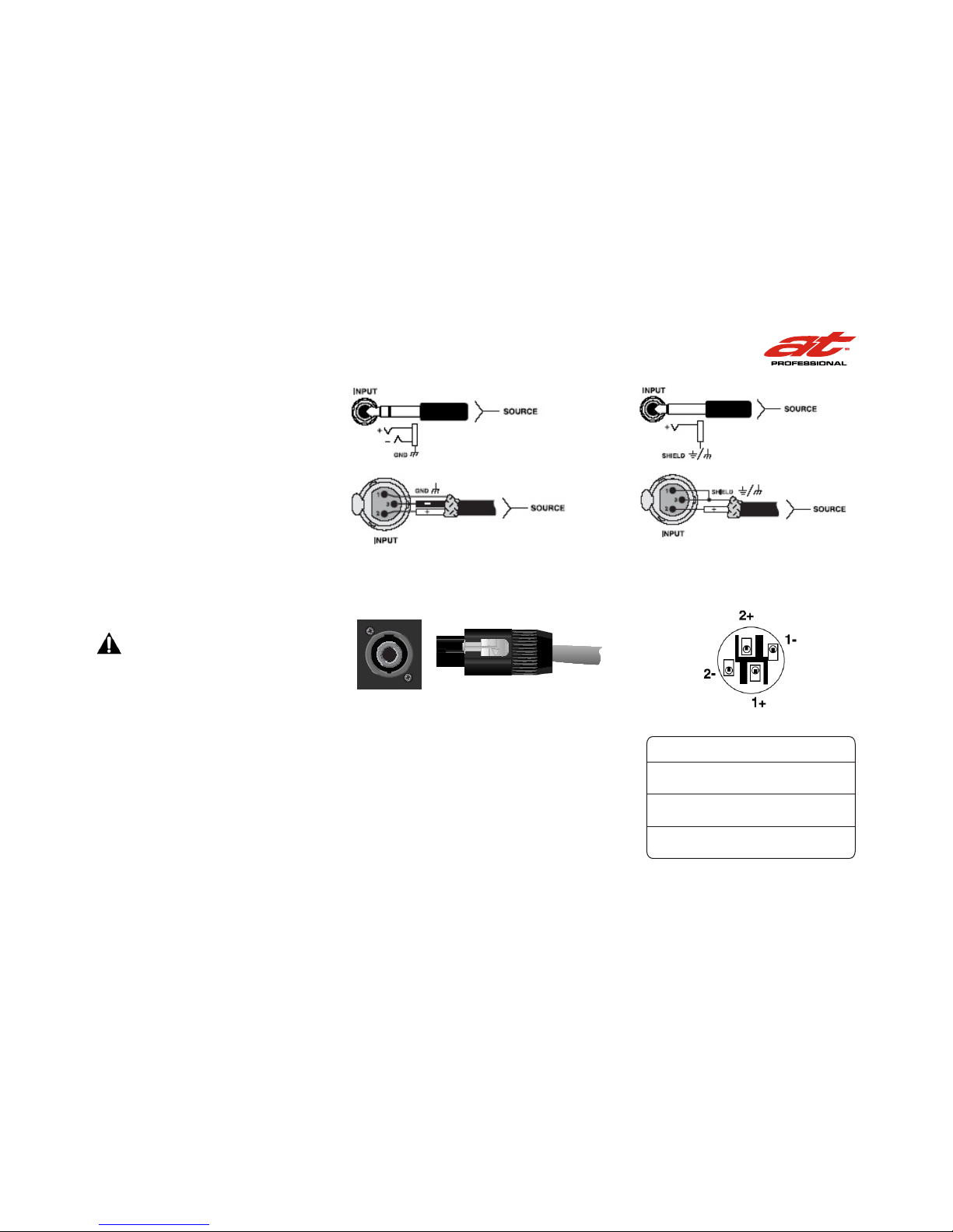
Figure 2.2
Balanced Input
Connector Wiring
Figure 2.3
Unbalanced Input
Connector Wiring
Figure 2.4
Left: Speakon Output Connector on Back Panel
Right: Speakon Cable Connector
OUTPUT ASSIGNMENT
PIN 1+ :
PIN 1- :
SIGNAL
GROUND
PIN 1+ :
PIN 1- :
SIGNAL
GROUND
PIN 1+ :
PIN 1- :
SIGNAL
GROUND
OUTPUT A
OUTPUT B
BRIDGE
2.4 Choose Input Wire and Connectors
AT Audio recommends using pre-built or professionally
wired, balanced line (two-conductor plus shield), 22-24
gauge cables and connectors. Depending upon which amplifier input you choose, you should use either 3-pin male
XLR connectors, TRS phone connectors, or terminal forks
at the amplifier inputs.
Unbalanced line may also be used but may result in noise
over long cable runs.
Note: Amplifier input connectors not used for audio signal
input may be used for daisy-chaining of the audio signal
to other components.
Figure 2.2 shows connector pin assignments for balanced
wiring, and Figure 2.3 shows connector pin assignments
for unbalanced wiring.
NOTE: Custom wiring should only be performed by qualified personnel.
2.5 Choose Output Wire and Connectors
AT Audio recommends using pre-built or professionally
wired, highquality, two- or four-conductor, heavy gauge
speaker wire and connectors. You may use two 4-pole Speakon connectors (Figure2.4 and Table 1) or banana plugs,
spade lugs, To prevent the possibility of short-circuits, wrap or otherwise insulate exposed loudspeaker cable connectors.
Using the guidelines below, select the appropriate
size of wire based on the distance from amplifier
to speaker.
Distance Wire Size
up to 25 ft. 16 AWG
26-40 ft. 14 AWG
41-60 ft. 12 AWG
61-100 ft. 10 AWG
101-150 ft. 8 AWG
151-250 ft. 6 AWG
CAUTION: Never use shielded cable for output wiring.
M Series Power Amplifiers
Page 8
OFF
80Hz 125Hz
LOW PASS -A
LINK A
LINK B
INPUT A
INPUT B
PIN1:
PIN2:
PIN3:
SIGNAL GND
SIGNAL +
SIGNAL -
PIN1:
PIN2:
PIN3:
SIGNAL GND
SIGNAL +
SIGNAL -
OFF 35Hz 80Hz
HIGH PASS -A
STEREO PARALLEL
BRIDGE
MODE
OUTPUT B
Push To Reset
26dB
32dB
0.775V
GAIN
~2202 40V 16A 50/60Hz
OUTPUT A
35Hz
HIGH PASS -B
LIMITER
OFFON
80Hz
LOW PASS -B
GROUND
LIFT
GROUND
21 000W
21 600W
OFF
80Hz
OFF 125Hz
N15067
M2000
1+ Channel B Positive
1 - Channel B Negative
2+ Bridge Positive
2 - Bridge Negative
1+ Channel A Positive
1 - Channel A Negative
2+ Channel B Positive
2 - Channel B Negative
R
Speakon 1
R
Speakon 2
page 8 Operation Manual
2 Setup
2.6 Wire Your System
2.6.1 Stereo Mode
SPEAKERS
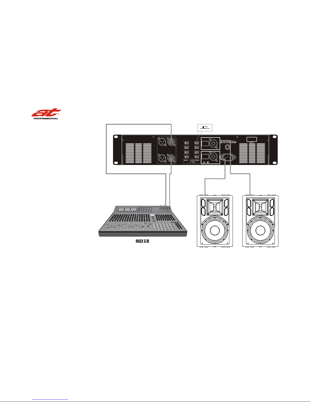
Figure 2.5
System Wiring, Stereo Mode
Typical input and output wiring is shown in Figure 2.5.
M SeriesPower Amplifiers
MODE
STEREO PAR ALLEL BRIDGE
Page 9
OFF
80Hz 125Hz
LOW PASS -A
LINK A
LINK B
INPUT A
INPUT B
PIN1:
PIN2:
PIN3:
SIGNAL GND
SIGNAL +
SIGNAL -
PIN1:
PIN2:
PIN3:
SIGNAL GND
SIGNAL +
SIGNAL -
OFF 35Hz 80Hz
HIGH PASS -A
STEREO PARALLEL
BRIDGE
MODE
OUTPUT B
Push To Reset
26dB
32dB
0.775V
GAIN
~2202 40V 16A 50/60Hz
OUTPUT A
35Hz
HIGH PASS -B
LIMITER
OFFON
80Hz
LOW PASS -B
GROUND
LIFT
GROUND
21 000W
21 600W
OFF
80Hz
OFF 125Hz
N15067
M2000
1+ Channel B Positive
1 - Channel B Negative
2+ Bridge Positive
2 - Bridge Negative
1+ Channel A Positive
1 - Channel A Negative
2+ Channel B Positive
2 - Channel B Negative
R
Speakon 1
R
Speakon 2
Operation Manual page 9
2 Setup
2.6.2 Parallel Mode
SPEAKERS
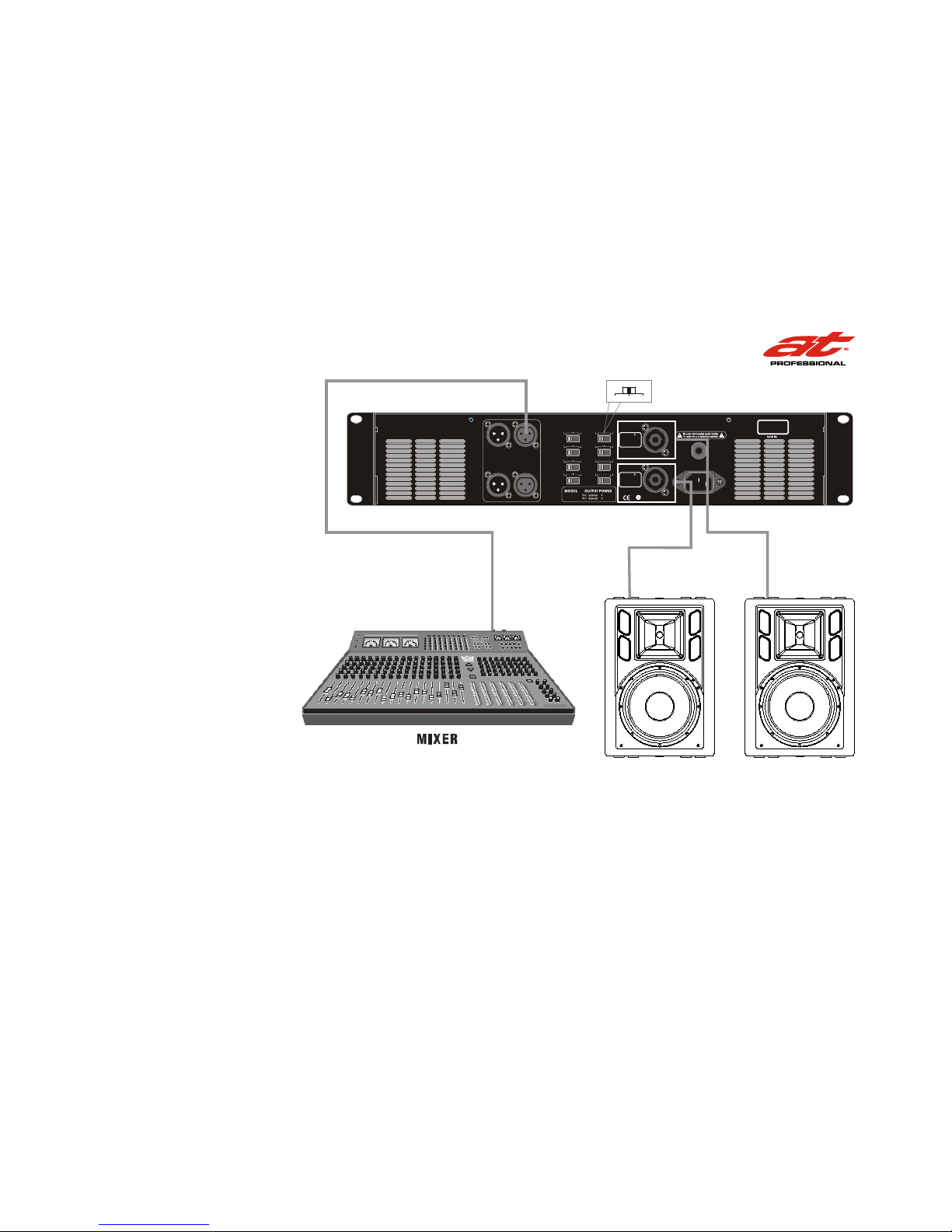
Figure 2.6
System Wiring, Parallel Mode
Typical input and output wiring is shown in Figure 2.6.
M Series Power Amplifiers
MODE
STEREO PARALLEL BRIDGE
Page 10
OFF
80Hz 125Hz
LOW PASS -A
LINK A
LINK B
INPUT A
INPUT B
PIN1:
PIN2:
PIN3:
SIGNAL GND
SIGNAL +
SIGNAL -
PIN1:
PIN2:
PIN3:
SIGNAL GND
SIGNAL +
SIGNAL -
OFF 35Hz 80Hz
HIGH PASS -A
STEREO PARALLEL
BRIDGE
MODE
OUTPUT B
Push To Reset
26dB
32dB
0.775V
GAIN
~2202 40V 16A 50/60Hz
OUTPUT A
35Hz
HIGH PASS -B
LIMITER
OFFON
80Hz
LOW PASS -B
GROUND
LIFT
GROUND
21 000W
21 600W
OFF
80Hz
OFF 125Hz
N15067
M2000
1+ Channel B Positive
1 - Channel B Negative
2+ Bridge Positive
2 - Bridge Negative
1+ Channel A Positive
1 - Channel A Negative
2+ Channel B Positive
2 - Channel B Negative
R
Speakon 1
R
Speakon 2
page 10 Operation Manual
2 Setup
2.6.3 Bridge-Mono Mode
2.6.4 Low Cut Filter
2.6.5 Low Pass Filter
2.6.6 Limiter
SPEAKERS
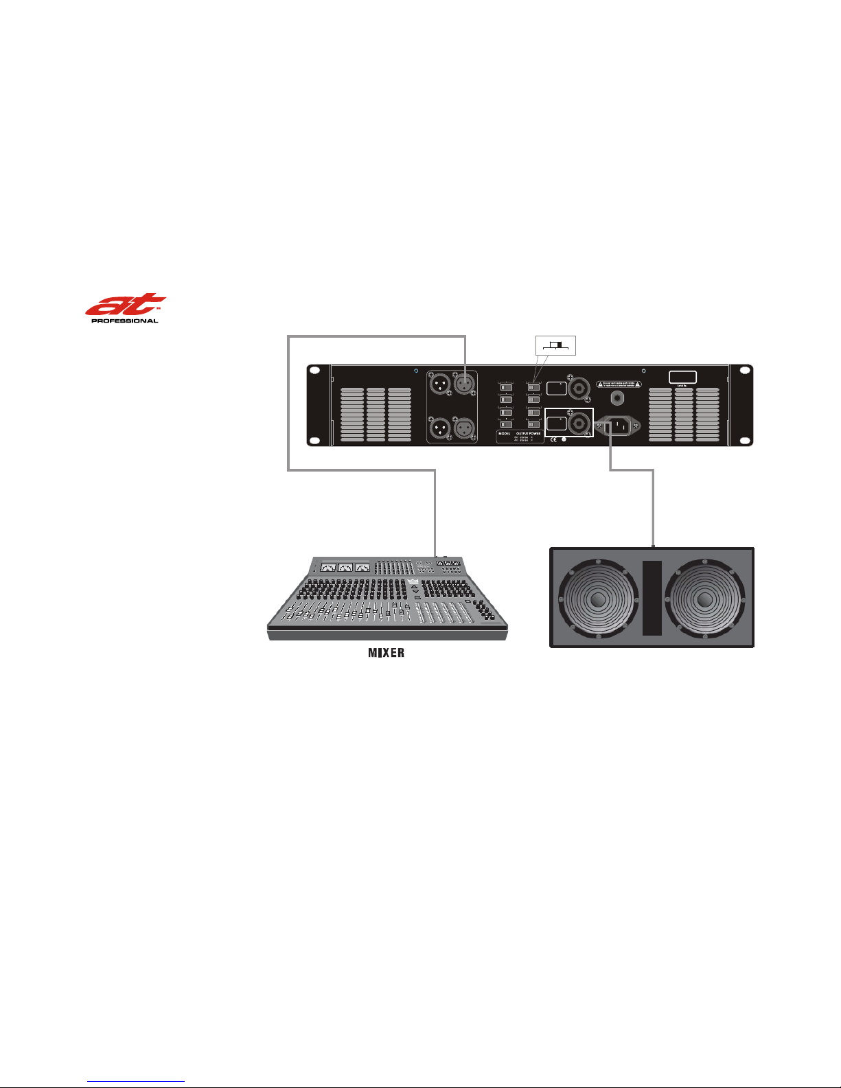
Figure 2.7
System Wiring, Bridge-Mono Mode
Typical input and output wiring is shown in Figure 2.7.
Low Cut Filter cuts off signal frequency below 30/80Hz or 50Hz
to avoid it muddy your sound when this amplifier matching
some full range speakers.
Low Pass Filter lets it can only response frequency below
80Hz or 125Hz without extra crossovers when matching
subwoofers.
To avoid serious clips when long term operation at dynamic
signal input.
M SeriesPower Amplifiers
MODE
STEREO PARALLEL BRIDGE
Page 11

Operation Manual page 11
2.7 Connect to AC Mains
2 Setup
Connect your amplifier to the AC mains power source (power outlet) with the supplied AC power cordset. First, connect the IEC end of the cordset to the IEC connector on
the amplifier; then, plug the other end of the cordset to
the AC mains.
WARNING: The third prong of this connector(ground) is an important safety feature. Do not attempt
to disable this ground connection by using an adapter or other methods.
Amplifiers don t create energy. The AC mains voltage and
current must be sufficient to deliver the power you expect.
You must operate your amplifier from an AC mains power
source with not more than a 10% variation above or a 15%
variation below the amplifier s specified line voltage
and within the specfied frequency requirements (indicated
on the amplifier s back panel label). If you are unsure of
the output voltage of your AC mains, please consult your
electrician.
2.8 Startup Procedure
Use the following procedure when first turning on your
amplifier:
1. Turn down the level of your audio source.
2. Turn down the level controls of the amplifier.
3. Turn on the Power switch. The Power indicator
should glow.
4. Turn up the level of your audio source to an optimum
level.
5. Turn up the Level controls on the amplifier until the
desired loudness or power level is achieved.
6. Turn down the level of your audio source to its normal
range.
If you ever need to make any wiring or installation changes,
do not forget to disconnect the power cord.
M Series Power Amplifiers
Page 12

page 12 Operation Manual
3 Operation
3.1 Precautions
Your amplifier is protected from internal and external
faults, but you should still take the following precautions
for optimum performance and safety:
1. Before use, your amplifier first must be configured for
proper operation, including input and output wiring
hookup. Improper wiring can result in serious operat ing difficulties.
2. Use care when making connections, selecting signal
sources and controlling the output level. The load you
save may be your own!
3. Do not short the ground lead of an output cable to the
input signal ground. This may form a ground loop and
cause oscillations.
4. WARNING: Never connect the output
to a power supply, battery or power
main. Electrical shock may result.
5. Tampering with the circuitry, or making unauthorized
circuit changes may be hazardous and invalidates all
agency listings.
6. Do not operate the amplifier with the red Clip LEDs
constantly flashing.
7. Do not overdrive the mixer, which will cause clipped
signal to be sent to the amplifier. Such signals will be
reproduced with extreme accuracy, and loudspeaker
damage may result.
8. Do not operate the amplifier with less than the rated
load impedance. Due to the amplifier s output prot ection, such a configuration may result in premature
clipping and speaker damage. Remember: AT is not
liable for damage that results from overdriving other
system components.
Remember: AT Audio is not liable for damage that results from overdriving other system components.
M SeriesPower Amplifiers
Page 13
dB
0
8
-
dB
0
8
-
I
O
PROTECT
CLIP
SIGNAL
ACTIVE
PROTECT
CLIP
SIGNAL
ACTIVE
POWERCH A CH B
M2000
OFF
80Hz 125Hz
LOW PASS -A
LINK A
LINK B
INPUT A
INPUT B
PIN1:
PIN2:
PIN3:
SIGNAL GND
SIGNAL +
SIGNAL -
PIN1:
PIN2:
PIN3:
SIGNAL GND
SIGNAL +
SIGNAL -
OFF 35Hz 80Hz
HIGH PASS -A
STEREO PARALLEL
BRIDGE
MODE
OUTPUT B
Push To Reset
26dB
32dB
0.775V
GAIN
~2202 40V 16A 50/60Hz
OUTPUT A
35Hz
HIGH PASS -B
LIMITER
OFFON
80Hz
LOW PASS -B
GROUND
LIFT
GROUND
21 000W
21 600W
OFF
80Hz
OFF
125Hz
N15067
M2000
1+ Channel B Positive
1 - Channel B Negative
2+ Bridge Positive
2 - Bridge Negative
1+ Channel A Positive
1 - Channel A Negative
2+ Channel B Positive
2 - Channel B Negative
R
Speakon 1
R
Speakon 2
Operation Manual page 13
3 Operation
2
Power Switch
Ch-B Power
Indicator
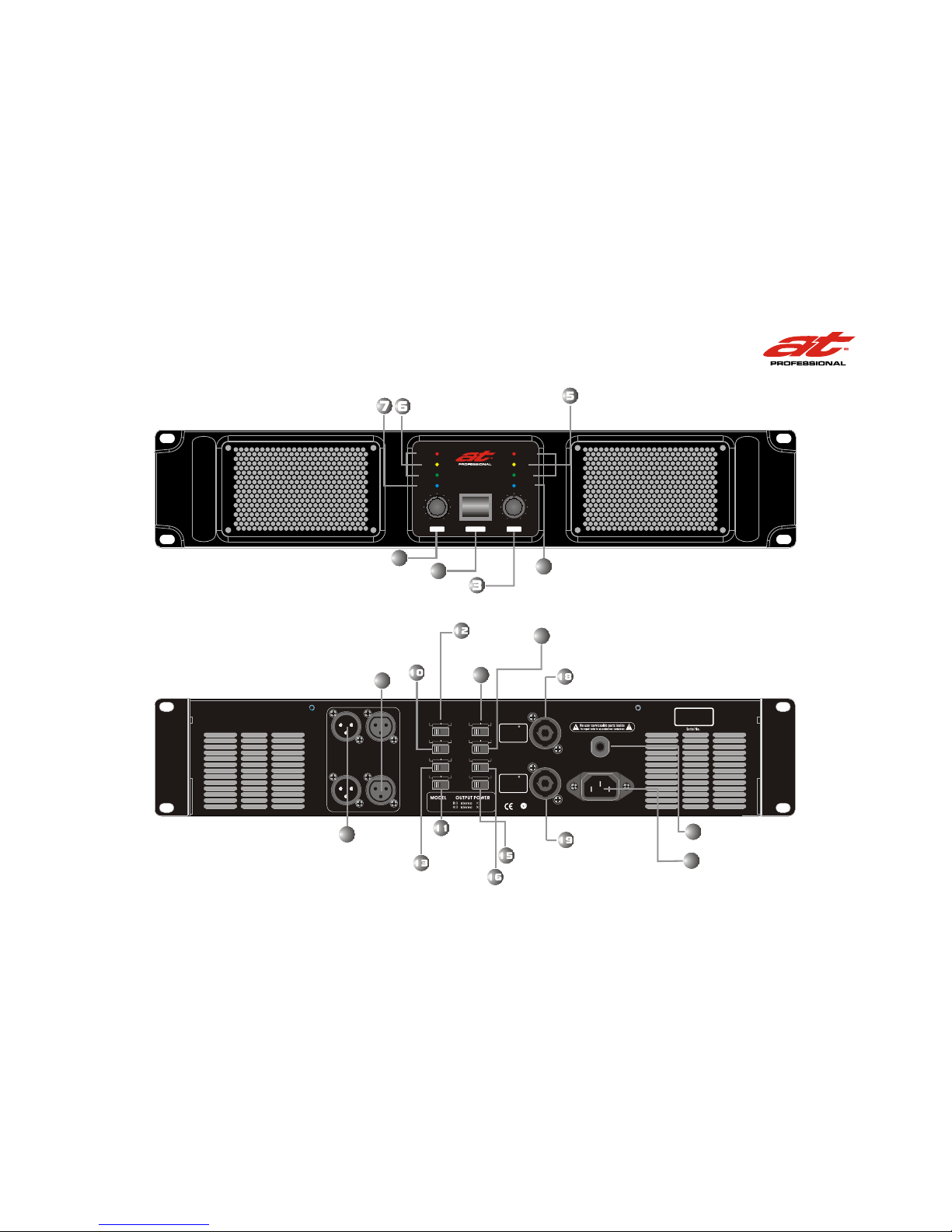
3.2 Front Panel Controls and Indicators
3.3 Back Panel Controls and Connectors
1
Ch-A Level
Control
Ch-B Level
Control
4
Ch-A Signal,
Clip& PROT
Ch-A Power
Indicator
8
Inputs(XLR)
9
Outputs(XLR)
14
20
Reset Switch
21
IEC Power Cord
Connector
Ch-A
Output
Ch-B
Output
Ground lift switch
Limiter switch
17
Input Sensitivity
Switch
Stereo/Parallel/
Bridge Switch
Low pass-B
switch
High pass-B
switch
High pass-A
switch
Low pass-A
switch
Ch-B Signal,
Clip& PROT
M Series Power Amplifiers
Page 14
page 14 Operation Manual
4 Specifications
M SeriesPower Amplifiers
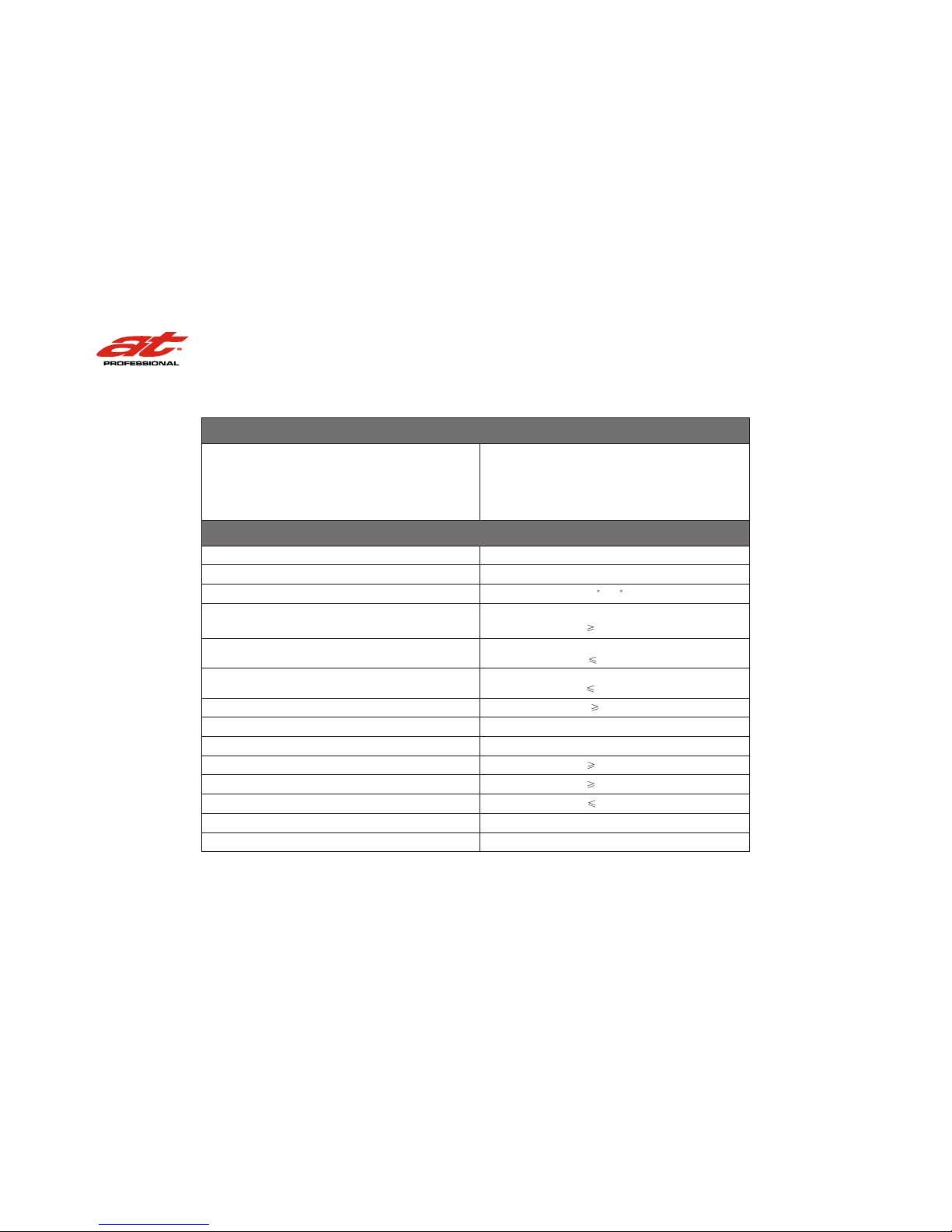
Minimum Guaranteed Power
Performance
Damping Factor (8 ohm): 20 Hz to 400 Hz
Low Cut:Linkwitz-Riley(24dB/Octave)
Low Pass:Linkwitz-Riley(24dB/Octave)
1 kHz with 0.5% THD
Stereo, 4 ohms (per ch.)
Stereo, 8 ohms (per ch.)
Bridge mono, 8 ohms
1600W
1000W
3000W
Sensitivity (volts RMS) for full rated power at 8 ohms
Frequency Response (at 1 watt, 20Hz - 25 kHz)
Phase Response (at 1 watt , 20Hz to 20 kHz)
Signal to Noise Ratio below rated power
A-weighted
Total Harmonic Distortion (THD) at 1 full bandwidth power,
from 20 Hz to 20 kHz
Intermodulation Distortion (IMD) 60 Hz and 7 kHz at 4:1,
from full rated output to -35 dB
Crosstalk (below rated power, 20 Hz to 20 kHz)
Common Mode Rejection (CMR)(20 Hz to 1 kHz)
DC Output Offset (Shorted input)
Input Impedance (nominally balanced, nominally unbalanced)
Voltage Gain (at maximum level setting)
41.2dB gain at 0.775volt sensitivity
0.775V, 32dB, 26dB
+0dB, -0.5dB
+10 ,-20
Off/80Hz/125Hz
Off/35Hz/80Hz
760
-65dB
-60dB
107dB
0.1%
10mV
0.05%
20 kilohms, 10 kilohms
M2000
M2000
Page 15
Operation Manual Page 15
4 Specifications
M Series Power Amplifiers
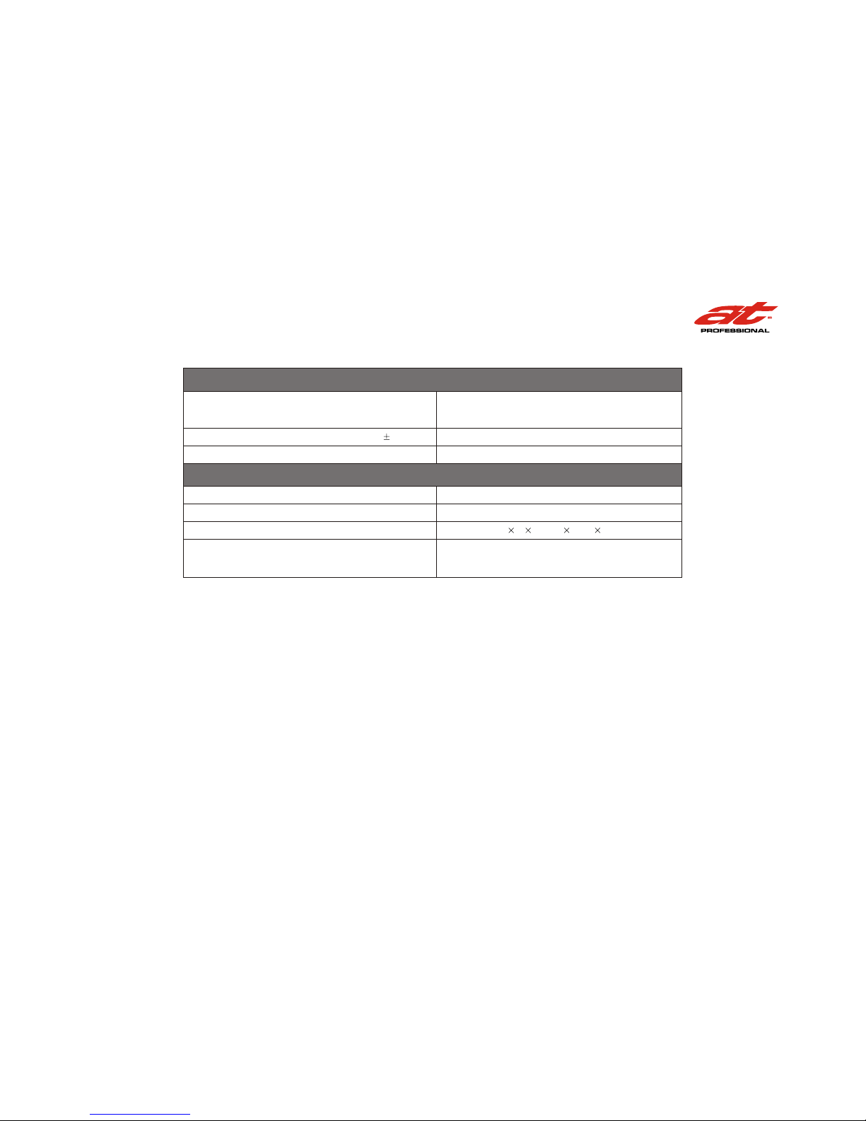
Minimum Guaranteed Power
Construction
Performance
AC Line Voltage and Frequency Configurations Available ( 10%)
AC Line Current (both amplifiers draw no more than 90 watts at idle)
Ventilation
Cooling
Dimensions
Weight
Net
Shipping
H W D: 89mm 483mm 462mm
Flow-through ventilation from front to back
Proportional speed fan
15A
23kg
26kg
~220-240 V and 50/60 Hz
Load Impedance (Note: Safe with all types of loads)
Stereo
Bridge Mono
4-8 ohms
8 ohms
M2000M2000
M2000
Page 16

 Loading...