

Page 1
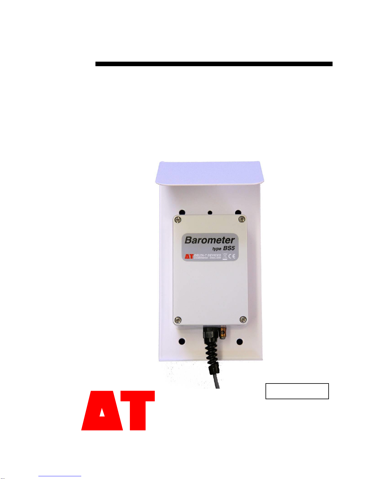
User Manual for the
Barometer
type BS5
Delta-T Devices Ltd
BS5-UM-3
Page 2

Notices
Copyright
All rights reserved. Under the copyright laws, this manual may not be
copied, in whole or in part, without the written consent of Delta-T Devices
Ltd. Under the law, copying includes translation into another language.
Copyright © 2015 Delta-T Devices Limited
CE Conformity
The BS5 Barometer conforms to EU regulations regarding
electromagnetic emissions and susceptibility and is CE marked by
the manufacturer.
For certificates look on our website at www.delta-t.co.uk
Warnings
To maintain conformance to CE standards, the equipment must be used
as described in this manual. Modifications to the equipment may
invalidate CE certifications.
Delta-T Devices Ltd reserves the right to change the designs and
specifications of its products at any time without prior notice.
Author
Stephen Nobbs, Nick Webb.
User Manual Version: 3 Aug 2015
For use with Climatronics M102663 User Manual
(available from www.climatronics.com).
Delta-T Devices Ltd
130 Low Road, Burwell
Cambridge CB25 0EJ
UK
Page 3

BS5 User Manual v2.0 3
Contents
Introduction 4
About the Manual 4
Features 4
Overview 5
Instructions 7
Assembly Instructions 7
Operation for GP1 9
Operation for DL2e 12
Operation for GP2 Loggers 16
Specification 18
Recalibration Period 18
Appendix 18
Warranty and service 19
Terms and conditions of sale 19
Service and spares 20
Technical support 20
Page 4

4 Introduction BS5 User Manual v2.0
Introduction
About the Manual
This user manual is intended to be used alongside the Climatronics
M102663 User Manual which is available from the Climatronics website
www.climatronics.com. It gives instructions on how to connect the BS5 to
Delta-T Data Loggers and how to successfully set-up programs for a
range of pressure measurements.
Features
The BS5 barometric pressure sensor offers selectable full scale analogue
output ranges and a selectable pressure scale wrapped up in a
weatherproof housing with a sun shield. It is packaged with a 3m output
cable, and a mounting bracket for attachment to the Delta-T Weather
Station. The selectable output ranges make the sensor suitable for all
Delta-T loggers.
The BS5/N barometer version is supplied without the housing or mounting
bracket. It is intended for use in non-condensing atmospheres where the
housing is not needed.
The barometer uses the rugged Climatronics 102663 pressure sensor for
accurate and stable measurement of barometric pressure.
The pressure transmitter requires a power source of 10-16VDC, 10mA at
12VDC.
Note: when used with DL2e or GP1 loggers these loggers must be
powered externally from a 12V supply for the barometer to work (taking
into account voltage drops in the logger).
Page 5
BS5 User Manual v2.0 Introduction 5
Overview
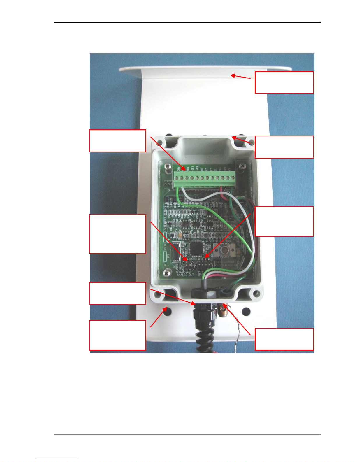
Figure 1. BS5 sensor overview
Earthing Point
Mounting
Holes
6.75mm dia.
Cable Strain
Relief
Output Range
DIP Switches
See fig. 4 for
more detail
Measurement
Range DIP
Switches
Weatherproof
Enclosure
Wiring
Terminal
Sun Shield /
Bracket
Page 6
6 Introduction BS5 User Manual v2.0
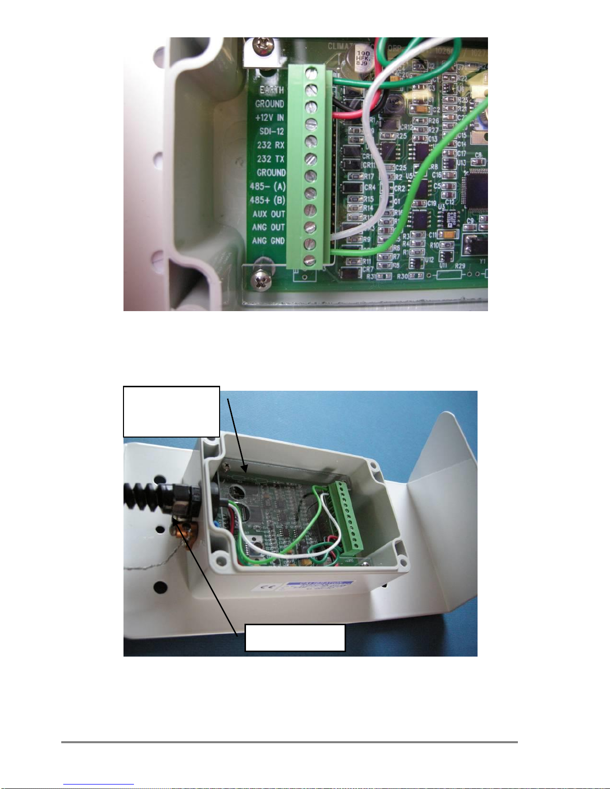
Figure 2. BS5 sensor terminal block
Figure 3. BS5 sensor case
Insert
Desiccant in
case
Breather
Page 7
BS5 User Manual v2.0 Instructions 7
Instructions
Assembly Instructions
Complete systems supplied by Delta-T
The complete BS5 system is supplied with a 3m cable and two stainless
steel V-bolts for mounting. This enables it to be fitted to the mast of the
Delta-T Weather Station, or to any vertical post less than 55mm in
diameter.
Alternatively dispense with the V-bolts for mounting the backing plate
directly to any vertical surface.
The housing is designed for indoor or outdoor use. It is designed to
‘breathe’, and should not be totally immersed or flooded with water.
See also Climatronics User Manual rev F, section 3.0 INSTALLATION
Measurement Range Set-Up
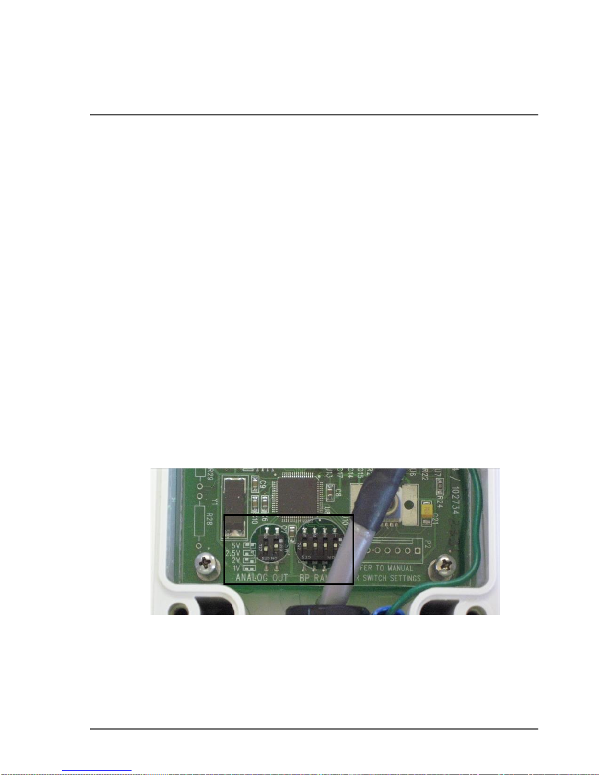
Two sets of DIP switches control the analogue output voltage and the
range of the sensor. These will need to be changed depending on the
logger used to measure the sensor and the range and accuracy of the
readings. Greater resolution can be achieved when measuring a smaller
range of pressure, this can be selected using the lower and upper limits.
Figure 4. SW1 & SW2 DIP Switches
Page 8

8 Instructions BS5 User Manual v2.0
ANALOG OUT
SW1-1
SW1-2
0-1000mV
ON
ON
0-2000mV
ON
OFF
0-2500mV
OFF
ON
Table 1. SW1 Analogue output selector
Four DIP switches provide the option of 16 pressure ranges, the largest
being 600-1100mbar. This enables the user to measure pressure at most
altitudes.
Lower
Limit
Upper
Limit
SW2-1
SW2-2
SW2-3
SW2-4
600
800
ON
ON
ON
ON
600
900
OFF
ON
ON
ON
600
1000
ON
OFF
ON
ON
600
1100
OFF
OFF
ON
ON
700
800
ON
ON
OFF
ON
700
900
OFF
ON
OFF
ON
700
1000
ON
OFF
OFF
ON
700
1100
OFF
OFF
OFF
ON
800
800
ON
ON
ON
OFF
800
900
OFF
ON
ON
OFF
800
1000
ON
OFF
ON
OFF
800
1100
OFF
OFF
ON
OFF
900
800
ON
ON
OFF
OFF
900
900
OFF
ON
OFF
OFF
900
1000
ON
OFF
OFF
OFF
900
1100
OFF
OFF
OFF
OFF
Table 2. SW2 Pressure range selector
See Climatronics User Manual section 5.0 USER INTERFACE for a
comprehensive table.
Page 9
BS5 User Manual v2.0 Instructions 9
Operation for GP1
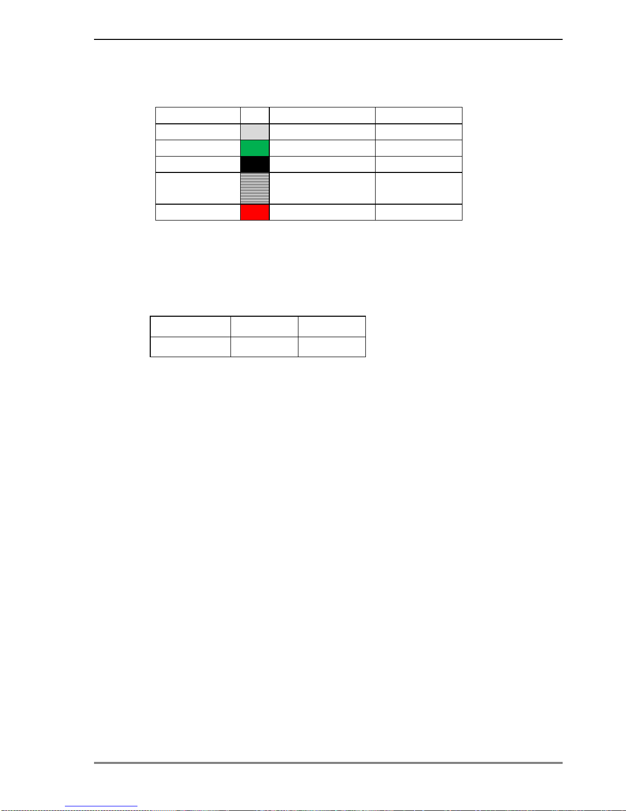
Wiring Diagram
Logger
Cable
Sensor
CH+
White/Clear
ANG OUT
CH -
Green
ANG GND
CH GND
Black
GROUND
CH GND
Screen (white
and black)
N/A
CH PWR
Red
+12V IN
See Climatronics User Manual
Sensor Set-up
SW1 analogue output switch setting
Range
SW1-1
SW1-2
0-2500mV
OFF
ON
Table 3. See Climatronics User Manual section 5.0 USER INTERFACE
Page 10
10 Instructions BS5 User Manual v2.0
Example GP1 Logger Program
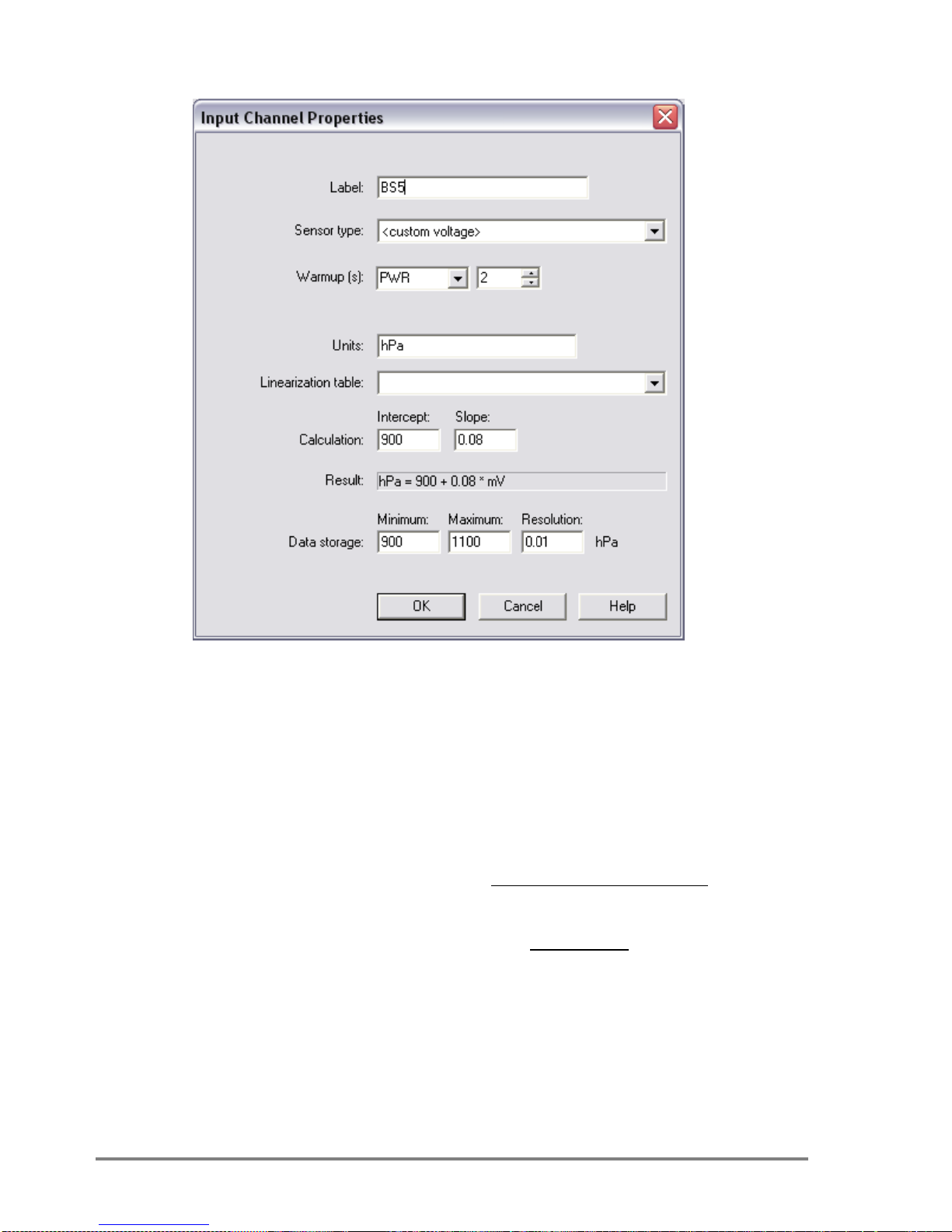
Figure 5. Channel Set-up for sensor range 900 to 1100 hPa
DeltaLINK 2.3 GP1 Program set up for a voltage channel
Sensor Type - custom voltage
Warm up - PWR 2 seconds
Units - hPa or mbars
Calculation - Intercept = Lower Limit
-
VoltageFullscale
Limit Lower - Limit Upper
Slope
- E.g.
08.0
2500
900 - 1100
Slope
- Full scale Voltage is set via the SW1 DIP
switch on the BS5 sensor PCB and is in mV
Data storage - Minimum = Lower Limit
- Maximum = Upper Limit
- Resolution = 0.01
Page 11
BS5 User Manual v2.0 Instructions 11
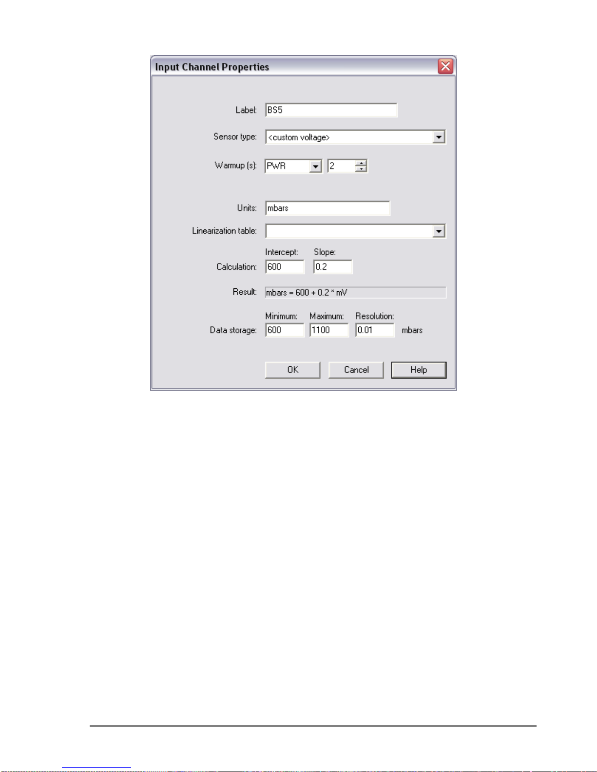
Example for a range of 600 to 1100 mbar
Figure 6. Channel Set-up for sensor range 600 to 1100 mbars
Page 12
12 Instructions BS5 User Manual v2.0
Operation for DL2e
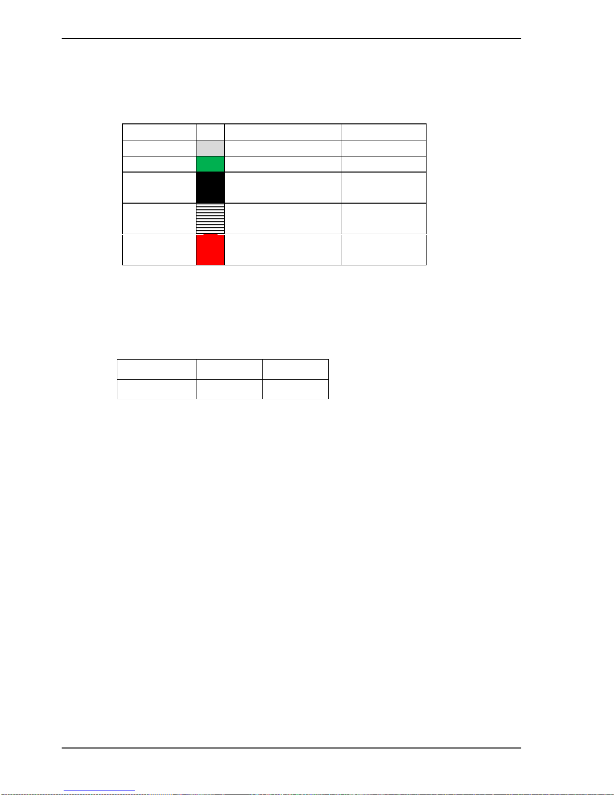
Wiring Diagram
Use a LAC1 15 channel card inside the logger
Logger
Cable
Sensor
CH1+
White/Clear
ANG OUT
CH1-
Green
ANG GND
CH61- or
CH62-
Black
GROUND
CH61- or
CH62-
Screen (white
and black)
N/A
CH63
N/O
Red
+12V IN
See Climatronics User Manual figure 3.4 ANALOG WIRING
Sensor Set-up
SW1 analogue output switch setting
Range
SW1-1
SW1-2
0-2000mV
ON
OFF
Table 5. See also Climatronics User Manual section 5.0 USER
INTERFACE
Strip back approximately 150mm of the cable insulation to allow for wiring
into any channel of the DL2e.
Page 13
BS5 User Manual v2.0 Instructions 13
Example Logger Program – DL2 Program Editor
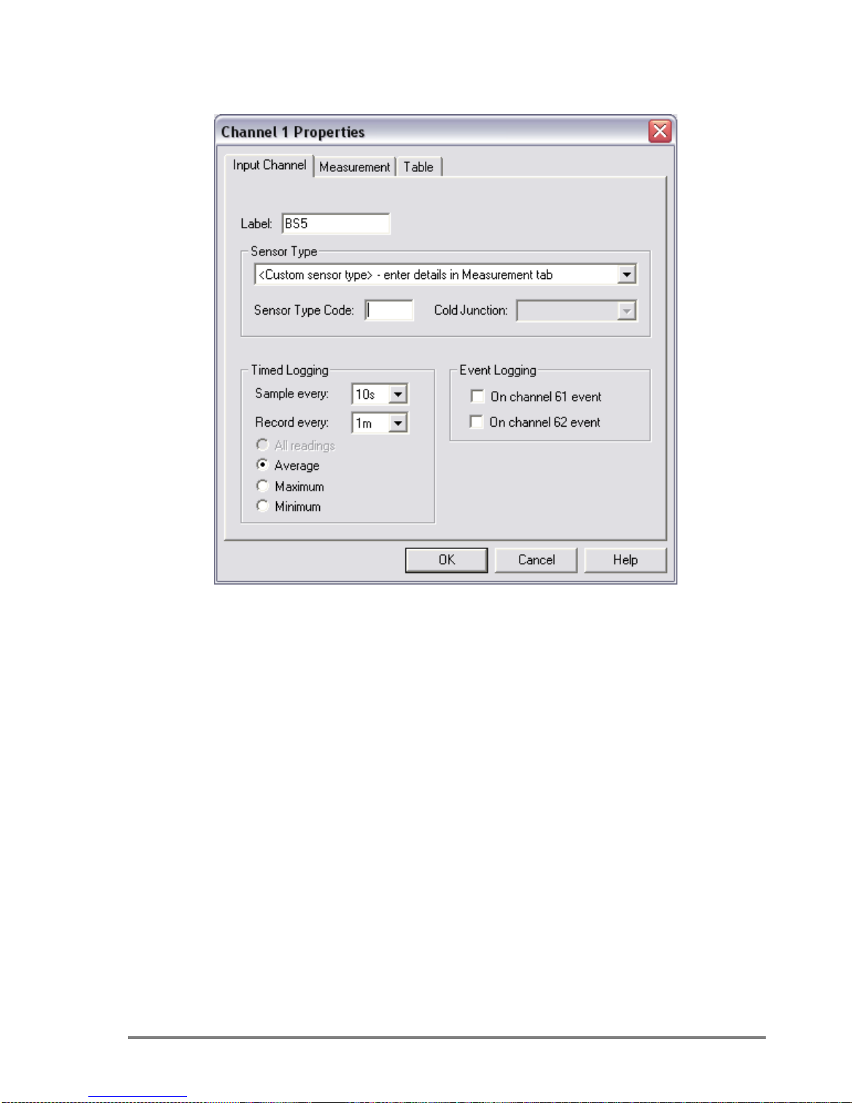
Figure 9. Channel Set-up for logging every 10s and recording every 1m
For complete program set up details see the logger user manual.
Sensor Type - custom sensor type.
Timed Logging - Sample every eg.10s
- Record every eg.1m
Electrical Measurement - DC Voltage
Lookup and interpolate in linearization table
o Create a new table by clicking the New Table button.
Page 14
14 Instructions BS5 User Manual v2.0
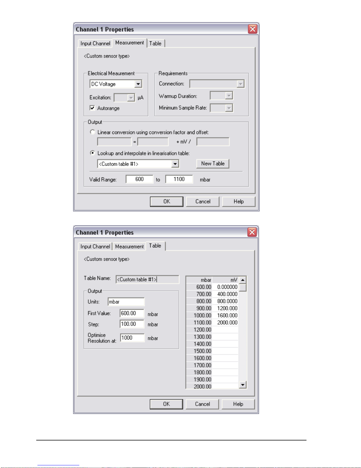
Figure 10. Channel Set-up for sensor range 600 to 1100 mbars
Figure 11. Table set-up for a sensor range 600 to 1100 mbars
Page 15
BS5 User Manual v2.0 Instructions 15
Units - hPa or mbar for example.
First Value - Depending on the range selected on the sensor
make the first value equal the lower limit. Eg. 600
Step - to give 4 or 5 steps to the upper limit. Eg. 100
Optimise Resolution - approx. 1000 mbars
Enter the mV value in the table for the appropriate pressure using
the formula or copy the table above for this pressure range.
(mV) voltagescale full
limitlimit
limit mbar
mV
lowerupper
lower
Eg.
1600
25.0
400
6001100
6001000
2000
mV
On the Measurement tab make sure the valid range is the same as
is selected on the SW1 DIP switches of the sensor. The sensor
should be set to 2000mV when used with a DL2e.
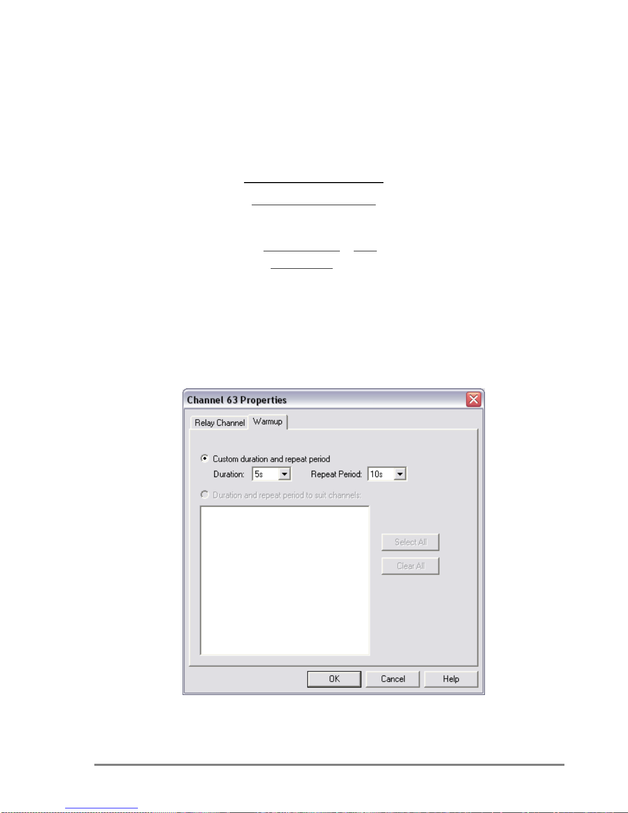
Set a warm up of 5 seconds on the same relay channel as used to
wire the sensor to the logger. The sensor takes over 1 second
to stabilise.
Figure 12. Warmup set-up for a logging rate of 10s
Set the Repeat period to the same frequency as the logging rate.
Page 16
16 Instructions BS5 User Manual v2.0
Operation for GP2 Loggers
Requirements
You need version 3.0.1 or later of the DeltaLINK 3 GP2 Sensor Library
installed. Get Installation instructions and an updated DeltaLINK sensor
library from http://www.delta-t.co.uk/software-downloads.asp
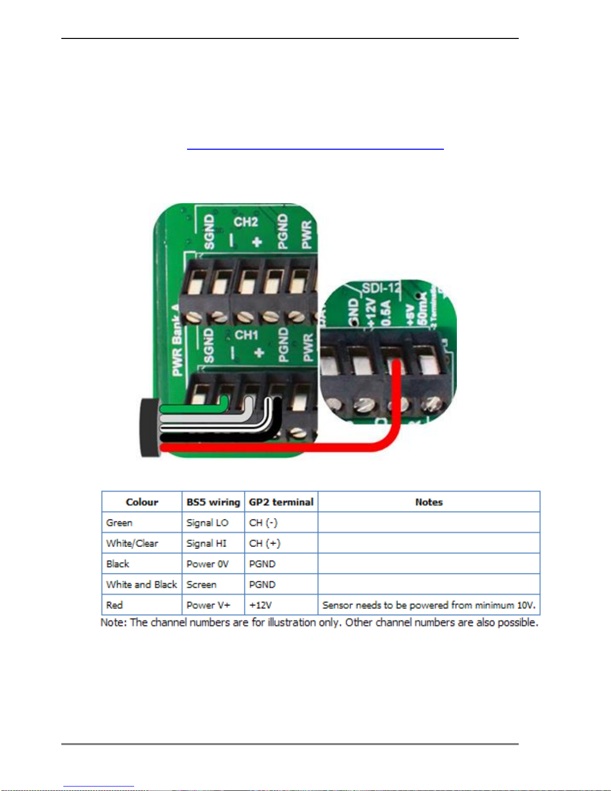
Wiring diagram
Page 17
BS5 User Manual v2.0 Instructions 17
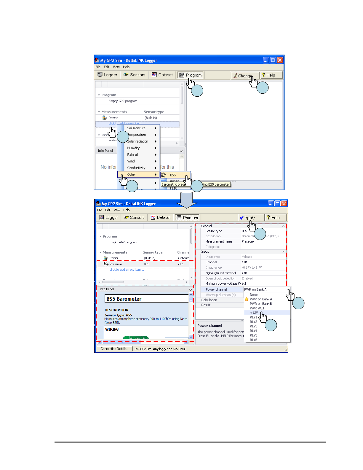
Program the GP2 Logger in 6 easy steps
Before you start ensure DeltaLINK is connected to your GP2 (or to the
GP2 Simulator).
1. Select Program.
2. Select Change.
3. Click on “Click to add new item”, under Measurement.
4. Select Other.
5. Select BS5.
6. Click on the far right of Power Channel to expose a drop- down
list of choices.
7. Select +12V.
8. Select Apply to send the program to the GP2 (or the simulator.)
3
4
5
1
2
8
6
7
Page 18

18 Instructions BS5 User Manual v2.0
This default program will read once an hour.
See the GP2 User Manual or online Help for further help.
Specification
For a comprehensive specification see Climatronics User Manual
Recalibration Period
“These sensors do not have a shelf life. The calibration performed on
them in 2011 is still good today if they have not been in use. The sensor
calibration is good until 1 year of use in the field”.
(Climatornics email received 17/4/2015)
The Climatronics Manual itself p11 says:
“6.0 Calibration
Calibration is performed against a NIST traceable standard. The
calibration coefficients are stored in non-volatile memory at the factory.
No user calibration is available. The sensor must be returned to
Climatronics if periodic calibration is desired.
7.0 Maintenance
Periodic cleaning of the sintered filter on the bottom of the unit may be
required in dusty conditions. Remove the filter from the bottom of the unit
and clean with distilled water.
Return of the sensor to Climatronics for a yearly recalibration is
recommended.”
Appendix
Climatronics M102663 User Manual (available from
www.climatronics.com)
Copyright - All rights reserved. Under the copyright laws, this manual may
not be copied, in whole or in part, without the written consent of
Climatronics Corp. Under the law, copying includes translation into
another language.
Page 19

BS5 User Manual v2.0 Warranty and service 19
Warranty and service
Terms and conditions of sale
Our Conditions of Sale (ref: COND: 1/00) set out Delta-T's legal
obligations on these matters. The following paragraphs summarise DeltaT's position but reference should always be made to the exact terms of
our Conditions of Sale, which will prevail over the following explanation.
Delta-T warrants that the goods will be free from defects arising out of the
materials used or poor workmanship for a period of twelve months from
the date of delivery.
Delta-T shall be under no liability in respect of any defect arising from fair
wear and tear, and the warranty does not cover damage through misuse
or inexpert servicing, or other circumstances beyond our control.
If the buyer experiences problems with the goods they shall notify Delta-T
(or Delta-T’s local distributor) as soon as they become aware of such
problem.
Delta-T may rectify the problem by replacing faulty parts free of charge, or
by repairing the goods free of charge at Delta-T's premises in the UK,
during the warranty period,
If Delta-T requires that goods under warranty be returned to them from
overseas for repair, Delta-T shall not be liable for the cost of carriage or
for customs clearance in respect of such goods. However, we much
prefer to have such returns discussed with us in advance, and we may, at
our discretion, waive these charges.
Delta-T shall not be liable to supply products free of charge or repair any
goods where the products or goods in question have been discontinued
or have become obsolete, although Delta-T will endeavour to remedy the
buyer’s problem.
Delta-T shall not be liable to the buyer for any consequential loss,
damage or compensation whatsoever (whether caused by the negligence
of the Delta-T, our employees or distributors or otherwise) which arise
from the supply of the goods and/or services, or their use or resale by the
buyer.
Delta-T shall not be liable to the buyer by reason of any delay or failure to
perform our obligations in relation to the goods and/or services, if the
delay or failure was due to any cause beyond the Delta-T’s reasonable
control.
Page 20

20 Warranty and service BS5 User Manual v2.0
Service and spares
Users in countries that have a Delta-T Distributor or Technical
Representative should contact them in the first instance.
Spare parts for our own instruments can be supplied from our works.
These can normally be despatched within a few working days of receiving
an order.
Spare parts and accessories for sensors or other products not
manufactured by Delta-T, may have to be obtained from our supplier, and
a certain amount of additional delay is inevitable.
No goods or equipment should be returned to Delta-T without first
obtaining the agreement of Delta-T or our distributor.
On receipt at Delta-T, the goods will be inspected and the user informed
of the likely cost and delay. We normally expect to complete repairs
within a few working days of receiving the equipment. However, if the
equipment has to be forwarded to our original supplier for specialist
repairs or recalibration, additional delays of a few weeks may be
expected.
Technical support
Technical Support is available on Delta-T products and systems. Users in
countries that have a Delta-T Distributor or Technical Representative
should contact them in the first instance.
Technical Support questions received by Delta-T will be handled by our
Tech Support team. Your initial enquiry will be acknowledged immediately
with a “T number” and an estimate of time for a detailed reply (normally a
few working days). Make sure to quote our T number subsequently so
that we can easily trace any earlier correspondence.
In your enquiry, always quote instrument serial numbers, software version
numbers, and the approximate date and source of purchase where these
are relevant.
Contact details:
Tech Support Team
Delta-T Devices Ltd
130 Low Road, Burwell, Cambridge CB25 0EJ, U.K.
email for technical support: [email protected]
email for repairs: [email protected]
web: www.delta-t.co.uk
Tel: +44 (0) 1638 742922
Fax: +44 (0) 1638 743155
 Loading...