

Asyst Falcon™ 300mm Loadport
Technical Manual
n
with Installation Instructions
e
r
l
mi
i
a
r
y
P
Tool Picture
Rev. Ax9 Date: 9/12/2008
P/N: 2000-6698-05
Copyright © 2008
Asyst Technologies, Inc.,
All rights reserved.


Disclaimers
This manual may not be reproduced, either wholly or in part, for any reason whatsoever, without prior written permission
from Asyst Technologies, Inc. (“Asyst”). Material contained in this manual is provided for informational purposes and is
subject to change without notice.
If this manual is marked “Preliminary” or “Draft,” then Asyst has not yet released a final version of the manual and the
manual is likely to be incomplete and will be revised. Contact Asyst at the address below to obtain a final copy of the
manual.
Manual Information
PCN: Unreleased
Part Number: 2000-6698-05
Date: 9/12/2008
Release: Ax9
Asyst Technologies, Inc.
46897 Bayside Parkway
Fremont, California 94538
Telephone: (510) 661-5000
FAX: (510) 661-5166
Technical Support: 1-800-342-SMIF
Falcon Technical Manual
Disclaimers
Trademarks
Asyst and the Asyst logo(s) are registered trademarks ® of Asyst Technologies, Inc.
ADVAN-TAG and Falcon are trademarks
All other product and company names mentioned herein may be trademarks and/or service marks of their respective
owners.
Equipment Modification
Any change, alteration, or modification to this equipment, as well as use of this equipment in a manner inconsistent with its
intended use will void this equipment’s warranty and may render this equipment unsafe for use or unfit for its intended
purposes.
Training and Languages
User training for equipment operation and maintenance is conducted in English. Translators are available on an as needed
basis. English versions of the manuals and other technical materials are provided and reviewed during the training. Please
contact the Asyst Training department or http://www.asyst.com for the training schedule and signup requirements.
Warranty
For warranty information, see Asyst’s Standard Terms and Conditions.
TM
of Asyst Technologies, Inc.
Draft Ax9 2000-6698-05 Page iii

Falcon Technical Manual
Reader Comments
Reader Comments
We welcome your comments regarding this manual. Your comments and suggestions
help us to improve our publications.
Please send comments and suggestions to:
Asyst Technologies, Inc.
Technical Publications Manager
46897 Bayside Parkway
Fremont CA 94538
Or fax: Attention—Tech Pubs Manager at 1-510-661-5185
Or email: TechPubs@asyst.com
Include the following:
Name:
Company:
Contact Phone # (in case we have questions):
Email:
Document Information (Name of document, Part Number, Revision):
Location of comment (page number or other reference):
Comments: (The more specific the comments, the more useful they are to us.)
Thank you for helping to improve the manuals and to maintain accuracy.
Page iv 2000-6698-05 Draf t Ax9

Acronym List
AGV Automated Guided Vehicle
APHD Active Pod Hold Down
ASCII American Standard Coding for Information Interchange
CAN Control Area Network
DSP Digital Signal Processor
EMI Electromagnetic Interference
EMO Emergency (Machine) Off
ESD Electrostatic Discharge
FIMS Front-opening Interface Mechanical Standard
FOUP Front Opening Unified Pod
K-Plate Kinematic Plate (also referred to as FOUP Advance Plate)
MGV Manually Guided Vehicle
OEM Original Equipment Manufacturer
OHS Overhead Hoist Shuttle
OHT Overhead Transport or Overhead Hoist Transport
PCB Printed Circuit Board
PN or P/N Part Number
RFID Radio Frequency IDentification
SEMI Semiconductor Equipment and Materials International
SMIF Standard Mechanical Interface
Draft Ax9 2000-6698-05 Page v

Falcon Technical Manual
Acronym List
Page vi 2000-6698-05 Draft Ax9

Revision History
This section gives an overview of the change history for the document.
Date Author Version Revision Information
11/15/2007 Catherine Day Ax1 Created using 2000-2414-05 Rev. C as a base.
1/10/2008 Catherine Day Ax2WIP WIP - Compiled for Mike F. Reference Only
3/21/2008 Catherine Day Ax2 Compiled for training class. Huge gaps in Installation,
Overview, Interfaces and Comm SW which we will attempt to
fill during training week 3/24-28.
3/28/2008 Catherine Day Ax3WIP WIP - Compiled for Tou Vang. Reference Only
04/08/2008 Catherine Day Ax3 Added redlines from Training class. Updated some images with
Beta images. Added verifications steps after Service procedures.
Added 100-240VAC Option. Added removal of FOUP Advance
under cover to affected Service procedures. Fleshed out
Overview Chapter.
04/18/2008 Catherine Day Ax4 Added redlines and new input from Tou Vang, Mike
Fahkrabadhi, Selby Sondergaard, Chi Yeh, Gary Durham, Grant
Imper, Pranav Desai. Updated more images.
04/24/2008 Catherine Day Ax5 Added redlines and new input from Tou Vang, Mike
Fahkrabadhi, Selby Sondergaard, Matt Hoang. Updated more
images.
5/30/2008 Catherine Day Ax6 Added Content from Tou Vang, Mike Fahkrabadhi and drawings
7/11/2008 Catherine Day Ax7 Expanded Software upgrade procedure and made it part of the
Service Chapter. Added input from John Green and Pranav
Desai. Made changes to all chapters and appendices.
Incorporated Beta 9 Software release notes, in many case
replacing existing content with info from the release notes.
Changed multiple illustrations. Updated all Assembly drawings
and PCB drawings.
Draft Ax9 2000-6698-05 Page vii

Falcon Technical Manual
Revision History
Date Author Version Revision Information
9/3/2008 Catherine Day Ax8 Added input from John Greene, Duc Le, Bob Carlson, and
Pranav Desai. Made changes to all chapters and appendices.
Incorporated Beta 10 Software release notes. Updated all
Assembly drawings and PCB drawings.
9/22/2008 Catherine Day Ax9 FINAL DRAFT -Removed information duplicated in the
Software Communications Manual and just reference that
document.
Added Remove and Replace instructions for the E84 and AC
Power Options. Edited all service procedures to show new front
panel removal. Updated all Assembly drawings and PCB
drawings.
Added customer cable routing for the E84 and AC Option to the
Installation Appendix. Added Details about the Vertical Brake.
Added comments/corrections from Chris Lueders, John Greene,
Duc Le, Bob Carlson and Tou Vang. Added Specifications from
Engineering and Matt Hoang.
Page viii 2000-6698-05 Draft Ax9

Falcon Technical Manual
Table of Contents
Disclaimers . . . . . . . . . . . . . . . . . . . . . . . . . . . . . . . . . . . . . . . . . . . . . . . . . . . . . .iii
Manual Information . . . . . . . . . . . . . . . . . . . . . . . . . . . . . . . . . . . . . . . . . . . . . . . .iii
Trademarks. . . . . . . . . . . . . . . . . . . . . . . . . . . . . . . . . . . . . . . . . . . . . . . . . . . . . .iii
Equipment Modification. . . . . . . . . . . . . . . . . . . . . . . . . . . . . . . . . . . . . . . . . . . . .iii
Training and Languages . . . . . . . . . . . . . . . . . . . . . . . . . . . . . . . . . . . . . . . . . . . .iii
Warranty . . . . . . . . . . . . . . . . . . . . . . . . . . . . . . . . . . . . . . . . . . . . . . . . . . . . . . . .iii
Reader Comments . . . . . . . . . . . . . . . . . . . . . . . . . . . . . . . . . . . . . . . . . . . . . . . .iv
Acronym List. . . . . . . . . . . . . . . . . . . . . . . . . . . . . . . . . . . . . . . . . . . . . . .v
Revision History . . . . . . . . . . . . . . . . . . . . . . . . . . . . . . . . . . . . . . . . . . .vii
Preface. . . . . . . . . . . . . . . . . . . . . . . . . . . . . . . . . . . . . . . . . . . . . . . . . . 1
About this Manual . . . . . . . . . . . . . . . . . . . . . . . . . . . . . . . . . . . . . . . . . . . . . . . . . 1
Conventions . . . . . . . . . . . . . . . . . . . . . . . . . . . . . . . . . . . . . . . . . . . . . . . . . . . . . 2
Chapter 1: Safety Information . . . . . . . . . . . . . . . . . . . . . . . . . . . . . . . . 3
Introduction . . . . . . . . . . . . . . . . . . . . . . . . . . . . . . . . . . . . . . . . . . . . . . . . . . . . . . 3
Chapter Summary . . . . . . . . . . . . . . . . . . . . . . . . . . . . . . . . . . . . . . . . . . . . . . 3
General Requirements . . . . . . . . . . . . . . . . . . . . . . . . . . . . . . . . . . . . . . . . . . . . . 4
General Safety. . . . . . . . . . . . . . . . . . . . . . . . . . . . . . . . . . . . . . . . . . . . . . . . . 4
Electrical Safety. . . . . . . . . . . . . . . . . . . . . . . . . . . . . . . . . . . . . . . . . . . . . . . . 4
Responsibility . . . . . . . . . . . . . . . . . . . . . . . . . . . . . . . . . . . . . . . . . . . . . . . . . . . . 5
Safety Tags. . . . . . . . . . . . . . . . . . . . . . . . . . . . . . . . . . . . . . . . . . . . . . . . . . . . . . 6
Safety Requirements. . . . . . . . . . . . . . . . . . . . . . . . . . . . . . . . . . . . . . . . . . . . . . . 7
ESD / EMI Precautions . . . . . . . . . . . . . . . . . . . . . . . . . . . . . . . . . . . . . . . . . . 7
EMO & Electrical Power . . . . . . . . . . . . . . . . . . . . . . . . . . . . . . . . . . . . . . . . . 8
Lockout/Tagout . . . . . . . . . . . . . . . . . . . . . . . . . . . . . . . . . . . . . . . . . . . . . . . . 8
Pinch Hazards . . . . . . . . . . . . . . . . . . . . . . . . . . . . . . . . . . . . . . . . . . . . . . . . . 9
During Installation. . . . . . . . . . . . . . . . . . . . . . . . . . . . . . . . . . . . . . . . . . . 11
Seismic . . . . . . . . . . . . . . . . . . . . . . . . . . . . . . . . . . . . . . . . . . . . . . . . . . . . . 12
Ergonomic . . . . . . . . . . . . . . . . . . . . . . . . . . . . . . . . . . . . . . . . . . . . . . . . . . . 12
Options . . . . . . . . . . . . . . . . . . . . . . . . . . . . . . . . . . . . . . . . . . . . . . . . . . . . . . . . 13
Wafer Mapper Option . . . . . . . . . . . . . . . . . . . . . . . . . . . . . . . . . . . . . . . . . . 13
100-240VAC Option. . . . . . . . . . . . . . . . . . . . . . . . . . . . . . . . . . . . . . . . . . . . 13
E84/PIO/ Interlock Option . . . . . . . . . . . . . . . . . . . . . . . . . . . . . . . . . . . . . . . 13
Draft Ax9 2000-6698-05 Page ix

Falcon Technical Manual
Tilt and Go Wheels Option. . . . . . . . . . . . . . . . . . . . . . . . . . . . . . . . . . . . . . . 13
Agency Compliance . . . . . . . . . . . . . . . . . . . . . . . . . . . . . . . . . . . . . . . . . . . . . . 14
FCC . . . . . . . . . . . . . . . . . . . . . . . . . . . . . . . . . . . . . . . . . . . . . . . . . . . . . . . . 14
Definition . . . . . . . . . . . . . . . . . . . . . . . . . . . . . . . . . . . . . . . . . . . . . . . . . 14
Compliance . . . . . . . . . . . . . . . . . . . . . . . . . . . . . . . . . . . . . . . . . . . . . . . 14
CE Mark. . . . . . . . . . . . . . . . . . . . . . . . . . . . . . . . . . . . . . . . . . . . . . . . . . . . . 14
Safety Features. . . . . . . . . . . . . . . . . . . . . . . . . . . . . . . . . . . . . . . . . . . . . . . . . . 15
DC Voltage . . . . . . . . . . . . . . . . . . . . . . . . . . . . . . . . . . . . . . . . . . . . . . . . . . 15
AC Option . . . . . . . . . . . . . . . . . . . . . . . . . . . . . . . . . . . . . . . . . . . . . . . . . . . 15
Pinch Hazard. . . . . . . . . . . . . . . . . . . . . . . . . . . . . . . . . . . . . . . . . . . . . . . . . 15
Port Door . . . . . . . . . . . . . . . . . . . . . . . . . . . . . . . . . . . . . . . . . . . . . . . . . 15
FOUP Advance . . . . . . . . . . . . . . . . . . . . . . . . . . . . . . . . . . . . . . . . . . . . 15
Moving and Handling . . . . . . . . . . . . . . . . . . . . . . . . . . . . . . . . . . . . . . . . . . . . . 16
Labeling. . . . . . . . . . . . . . . . . . . . . . . . . . . . . . . . . . . . . . . . . . . . . . . . . . . . . . . . 18
Chapter 2: Product Overview . . . . . . . . . . . . . . . . . . . . . . . . . . . . . . . 23
Product Description. . . . . . . . . . . . . . . . . . . . . . . . . . . . . . . . . . . . . . . . . . . . . . . 24
Major Components . . . . . . . . . . . . . . . . . . . . . . . . . . . . . . . . . . . . . . . . . . . . 25
Features. . . . . . . . . . . . . . . . . . . . . . . . . . . . . . . . . . . . . . . . . . . . . . . . . . . . . 26
Power. . . . . . . . . . . . . . . . . . . . . . . . . . . . . . . . . . . . . . . . . . . . . . . . . . . . . . . 26
Specifications . . . . . . . . . . . . . . . . . . . . . . . . . . . . . . . . . . . . . . . . . . . . . . . . . . . 27
FIMS Door. . . . . . . . . . . . . . . . . . . . . . . . . . . . . . . . . . . . . . . . . . . . . . . . . . . . . . 29
Features. . . . . . . . . . . . . . . . . . . . . . . . . . . . . . . . . . . . . . . . . . . . . . . . . . . . . 30
Ball Joint with Clamping for Port Door Alignment. . . . . . . . . . . . . . . . . . . 30
Simplified Twist and Pull Latch Key Drive . . . . . . . . . . . . . . . . . . . . . . . . 30
Sensors . . . . . . . . . . . . . . . . . . . . . . . . . . . . . . . . . . . . . . . . . . . . . . . . . . 31
Ground Path to FOUP Door. . . . . . . . . . . . . . . . . . . . . . . . . . . . . . . . . . . 31
Configurable Latch Key Over-Rotation. . . . . . . . . . . . . . . . . . . . . . . . . . . 31
Vertical-Horizontal Door Drive. . . . . . . . . . . . . . . . . . . . . . . . . . . . . . . . . . . . . . . 32
Features. . . . . . . . . . . . . . . . . . . . . . . . . . . . . . . . . . . . . . . . . . . . . . . . . . . . . 32
Single Motor for Two Axes. . . . . . . . . . . . . . . . . . . . . . . . . . . . . . . . . . . . 32
Upper Pulley/Brake/Encoder Assembly . . . . . . . . . . . . . . . . . . . . . . . . . . 33
Fan Assembly. . . . . . . . . . . . . . . . . . . . . . . . . . . . . . . . . . . . . . . . . . . . . . 33
FOUP Advance Subassembly. . . . . . . . . . . . . . . . . . . . . . . . . . . . . . . . . . . . . . . 34
Features. . . . . . . . . . . . . . . . . . . . . . . . . . . . . . . . . . . . . . . . . . . . . . . . . . . . . 35
Torque Tube with Cantilevered Supports. . . . . . . . . . . . . . . . . . . . . . . . . 35
Manual Load/Unload Push Button Switch . . . . . . . . . . . . . . . . . . . . . . . . 35
K-Plate Node PCB . . . . . . . . . . . . . . . . . . . . . . . . . . . . . . . . . . . . . . . . . . 36
Cam Activated Pod Hold Down . . . . . . . . . . . . . . . . . . . . . . . . . . . . . . . . 36
Page x 2000-6698-05 Draft Ax9

Falcon Technical Manual
Sensors . . . . . . . . . . . . . . . . . . . . . . . . . . . . . . . . . . . . . . . . . . . . . . . . . . 36
BOLTS Frame. . . . . . . . . . . . . . . . . . . . . . . . . . . . . . . . . . . . . . . . . . . . . . . . . . . 38
Main Components . . . . . . . . . . . . . . . . . . . . . . . . . . . . . . . . . . . . . . . . . . . . . 38
Light Display Node PCB. . . . . . . . . . . . . . . . . . . . . . . . . . . . . . . . . . . . . . 38
Excessive Wafer Protrusion Sensor. . . . . . . . . . . . . . . . . . . . . . . . . . . . . 38
Static Entry Node PCB. . . . . . . . . . . . . . . . . . . . . . . . . . . . . . . . . . . . . . . 39
Options . . . . . . . . . . . . . . . . . . . . . . . . . . . . . . . . . . . . . . . . . . . . . . . . . . . . . . . . 40
Wafer Mapper Assembly Option . . . . . . . . . . . . . . . . . . . . . . . . . . . . . . . . . . 40
100-240VAC Power Option . . . . . . . . . . . . . . . . . . . . . . . . . . . . . . . . . . . . . . 41
E84/PIO/Interlock Option. . . . . . . . . . . . . . . . . . . . . . . . . . . . . . . . . . . . . . . . 43
Components. . . . . . . . . . . . . . . . . . . . . . . . . . . . . . . . . . . . . . . . . . . . . . . 43
Tilt & Go Wheels Option . . . . . . . . . . . . . . . . . . . . . . . . . . . . . . . . . . . . . . . . 44
Operation Sequence. . . . . . . . . . . . . . . . . . . . . . . . . . . . . . . . . . . . . . . . . . . . . . 45
Chapter 3: Interfaces. . . . . . . . . . . . . . . . . . . . . . . . . . . . . . . . . . . . . . 49
Introduction . . . . . . . . . . . . . . . . . . . . . . . . . . . . . . . . . . . . . . . . . . . . . . . . . . . . . 49
Chapter Summary . . . . . . . . . . . . . . . . . . . . . . . . . . . . . . . . . . . . . . . . . . . . . 49
Communication Interfaces . . . . . . . . . . . . . . . . . . . . . . . . . . . . . . . . . . . . . . . . . 50
Status Indicator Lights. . . . . . . . . . . . . . . . . . . . . . . . . . . . . . . . . . . . . . . . . . . . . 51
Command for LED Configuration. . . . . . . . . . . . . . . . . . . . . . . . . . . . . . . . . . 51
Falcon Application Software . . . . . . . . . . . . . . . . . . . . . . . . . . . . . . . . . . . . . . . . 52
Using the Falcon GUI . . . . . . . . . . . . . . . . . . . . . . . . . . . . . . . . . . . . . . . . . . . . . 53
Accessing the GUI. . . . . . . . . . . . . . . . . . . . . . . . . . . . . . . . . . . . . . . . . . . . . 53
Navigating Overview . . . . . . . . . . . . . . . . . . . . . . . . . . . . . . . . . . . . . . . . . . . 55
System Icon Details. . . . . . . . . . . . . . . . . . . . . . . . . . . . . . . . . . . . . . . . . . . . 55
Wafer Status Screen . . . . . . . . . . . . . . . . . . . . . . . . . . . . . . . . . . . . . . . . 56
Service Mode Commands Screen . . . . . . . . . . . . . . . . . . . . . . . . . . . . . . 56
Motor Control Commands Screen . . . . . . . . . . . . . . . . . . . . . . . . . . . . . . 60
E84 Status Screen . . . . . . . . . . . . . . . . . . . . . . . . . . . . . . . . . . . . . . . . . . 61
LED Controls Screen . . . . . . . . . . . . . . . . . . . . . . . . . . . . . . . . . . . . . . . . 61
System Info Screen . . . . . . . . . . . . . . . . . . . . . . . . . . . . . . . . . . . . . . . . . 62
Setup Icon Details . . . . . . . . . . . . . . . . . . . . . . . . . . . . . . . . . . . . . . . . . . . . . 62
Host Communications . . . . . . . . . . . . . . . . . . . . . . . . . . . . . . . . . . . . . . . 63
Users and Passwords . . . . . . . . . . . . . . . . . . . . . . . . . . . . . . . . . . . . . . . 64
Axes Parameters . . . . . . . . . . . . . . . . . . . . . . . . . . . . . . . . . . . . . . . . . . . 65
E84 Configuration. . . . . . . . . . . . . . . . . . . . . . . . . . . . . . . . . . . . . . . . . . . 67
Wafer Mapper Parameters. . . . . . . . . . . . . . . . . . . . . . . . . . . . . . . . . . . . 67
DSP Firmware . . . . . . . . . . . . . . . . . . . . . . . . . . . . . . . . . . . . . . . . . . . . . 68
LED Setup . . . . . . . . . . . . . . . . . . . . . . . . . . . . . . . . . . . . . . . . . . . . . . . . 68
Draft Ax9 2000-6698-05 Page xi

Falcon Technical Manual
System Log Icon. . . . . . . . . . . . . . . . . . . . . . . . . . . . . . . . . . . . . . . . . . . . 69
Alarms Icon . . . . . . . . . . . . . . . . . . . . . . . . . . . . . . . . . . . . . . . . . . . . . . . 70
Diagnostics Icon . . . . . . . . . . . . . . . . . . . . . . . . . . . . . . . . . . . . . . . . . . . . . . 70
Chapter 4: Service. . . . . . . . . . . . . . . . . . . . . . . . . . . . . . . . . . . . . . . . 71
Overview. . . . . . . . . . . . . . . . . . . . . . . . . . . . . . . . . . . . . . . . . . . . . . . . . . . . . . . 71
Safety Requirements. . . . . . . . . . . . . . . . . . . . . . . . . . . . . . . . . . . . . . . . . . . . . . 72
General Safety. . . . . . . . . . . . . . . . . . . . . . . . . . . . . . . . . . . . . . . . . . . . . . . . 72
Electrical Safety. . . . . . . . . . . . . . . . . . . . . . . . . . . . . . . . . . . . . . . . . . . . . . . 72
Mechanical Safety . . . . . . . . . . . . . . . . . . . . . . . . . . . . . . . . . . . . . . . . . . . . . 73
ESD Precautions . . . . . . . . . . . . . . . . . . . . . . . . . . . . . . . . . . . . . . . . . . . . . . 73
Tool and Fixture Requirements. . . . . . . . . . . . . . . . . . . . . . . . . . . . . . . . . . . . . . 73
Remove and Replace Falcon 74
Corrective Service Procedures. . . . . . . . . . . . . . . . . . . . . . . . . . . . . . . 81
Introduction . . . . . . . . . . . . . . . . . . . . . . . . . . . . . . . . . . . . . . . . . . . . . . . . . . . . . 81
CSP1: Replace Falcon K-Plate Node PCB . . . . . . . . . . . . . . . . . . . . . . . . . . 82
CSP2: Replace Falcon Door Node . . . . . . . . . . . . . . . . . . . . . . . . . . . . . . . . 89
CSP3: Replace Vertical/Horizontal Drive Motor . . . . . . . . . . . . . . . . . . . . . . 95
CSP4: Replace Pod Hold Down Motor Assembly . . . . . . . . . . . . . . . . . . . 106
CSP5: Replace Wafer Mapper Assembly . . . . . . . . . . . . . . . . . . . . . . . . . . 112
CSP6: Replace Display Node PCB . . . . . . . . . . . . . . . . . . . . . . . . . . . . . . 117
CSP7: Replace Static Entry Node . . . . . . . . . . . . . . . . . . . . . . . . . . . . . . . 121
CSP8: Replace Link Manager/CPU . . . . . . . . . . . . . . . . . . . . . . . . . . . . . . 127
CSP9: Replace Latch Key Motor Assembly . . . . . . . . . . . . . . . . . . . . . . . . 131
CSP10: Replace V/H Drive Upper Pulley Assembly . . . . . . . . . . . . . . . . . . 137
CSP11: Replace Vertical Drive Belt . . . . . . . . . . . . . . . . . . . . . . . . . . . . . . 147
CSP12: Upgrade Falcon Software . . . . . . . . . . . . . . . . . . . . . . . . . . . . . . . 155
CSP13: Vertical Drive Belt Tensioning . . . . . . . . . . . . . . . . . . . . . . . . . . . . 161
CSP14: Remove and Replace E84 Board . . . . . . . . . . . . . . . . . . . . . . . . . 168
CSP15: Replace AC Power Supply . . . . . . . . . . . . . . . . . . . . . . . . . . . . . . 173
Chapter 5: Troubleshooting. . . . . . . . . . . . . . . . . . . . . . . . . . . . . . . . 179
Introduction . . . . . . . . . . . . . . . . . . . . . . . . . . . . . . . . . . . . . . . . . . . . . . . . . . . . 179
Collecting Falcon Files . . . . . . . . . . . . . . . . . . . . . . . . . . . . . . . . . . . . . . . . . . . 179
Emergency Removal of Pod . . . . . . . . . . . . . . . . . . . . . . . . . . . . . . . . . . . . . . . 182
Application. . . . . . . . . . . . . . . . . . . . . . . . . . . . . . . . . . . . . . . . . . . . . . . . . . 182
Procedure . . . . . . . . . . . . . . . . . . . . . . . . . . . . . . . . . . . . . . . . . . . . . . . . . . 182
Remove Host Tool’s End-Effector . . . . . . . . . . . . . . . . . . . . . . . . . . . . . 182
Removal Using Falcon Application. . . . . . . . . . . . . . . . . . . . . . . . . . . . . 182
Error Codes. . . . . . . . . . . . . . . . . . . . . . . . . . . . . . . . . . . . . . . . . . . . . . . . . . . . 185
Page xii 2000-6698-05 Draft Ax9

Falcon Technical Manual
Falcon Alarm Codes . . . . . . . . . . . . . . . . . . . . . . . . . . . . . . . . . . . . . . . . . . . . . 186
Auto Recovery. . . . . . . . . . . . . . . . . . . . . . . . . . . . . . . . . . . . . . . . . . . . . . . 188
About Alarm Codes . . . . . . . . . . . . . . . . . . . . . . . . . . . . . . . . . . . . . . . . . . . 189
Recovery Procedures. . . . . . . . . . . . . . . . . . . . . . . . . . . . . . . . . . . . . . . 189
About Alarm 1 “Position following error”. . . . . . . . . . . . . . . . . . . . . . . . . 190
About Alarm 2 “Vertical drive is not home”. . . . . . . . . . . . . . . . . . . . . . . 190
About Alarm 3 “Motion requested while already busy”. . . . . . . . . . . . . . 191
About Alarm 4 & 30 “Pod is missing” . . . . . . . . . . . . . . . . . . . . . . . . . . . 191
About Alarm 5 “Aborted by user” . . . . . . . . . . . . . . . . . . . . . . . . . . . . . . 192
About alarm 14, 24, 82, 83, 84, 86 & 87. . . . . . . . . . . . . . . . . . . . . . . . . 192
Abort/Failed Messages . . . . . . . . . . . . . . . . . . . . . . . . . . . . . . . . . . . . . . . . . . . 194
Troubleshooting . . . . . . . . . . . . . . . . . . . . . . . . . . . . . . . . . . . . . . . . . . . . . . . . 195
Error Types . . . . . . . . . . . . . . . . . . . . . . . . . . . . . . . . . . . . . . . . . . . . . . . . . 195
Factory Default Settings . . . . . . . . . . . . . . . . . . . . . . . . . . . . . . . . . . . . . . . . . . 198
Appendix A: Installation Instructions . . . . . . . . . . . . . . . . . . . . . . . . . 199
Introduction . . . . . . . . . . . . . . . . . . . . . . . . . . . . . . . . . . . . . . . . . . . . . . . . . . . . 199
Installing Falcon . . . . . . . . . . . . . . . . . . . . . . . . . . . . . . . . . . . . . . . . . . . . . . . . 200
Handling Cautions . . . . . . . . . . . . . . . . . . . . . . . . . . . . . . . . . . . . . . . . . . . . 200
Operating Caution . . . . . . . . . . . . . . . . . . . . . . . . . . . . . . . . . . . . . . . . . . . . 201
Installation Summary. . . . . . . . . . . . . . . . . . . . . . . . . . . . . . . . . . . . . . . . . . 201
Verify Asyst Supplied Materials. . . . . . . . . . . . . . . . . . . . . . . . . . . . . . . . . . . . . 201
Verify the OEM Supplied Materials. . . . . . . . . . . . . . . . . . . . . . . . . . . . . . . . . . 202
BOLTS Interface Mounting . . . . . . . . . . . . . . . . . . . . . . . . . . . . . . . . . . . . . 202
Power Cable . . . . . . . . . . . . . . . . . . . . . . . . . . . . . . . . . . . . . . . . . . . . . . . . 202
Grounding Cable . . . . . . . . . . . . . . . . . . . . . . . . . . . . . . . . . . . . . . . . . . . . . 203
Requirement. . . . . . . . . . . . . . . . . . . . . . . . . . . . . . . . . . . . . . . . . . . . . . 203
Assembly . . . . . . . . . . . . . . . . . . . . . . . . . . . . . . . . . . . . . . . . . . . . . . . . 203
Communications Cables . . . . . . . . . . . . . . . . . . . . . . . . . . . . . . . . . . . . . . . 203
Prepare for Mounting Falcon. . . . . . . . . . . . . . . . . . . . . . . . . . . . . . . . . . . . . . . 204
Mount Falcon to the Host Tool . . . . . . . . . . . . . . . . . . . . . . . . . . . . . . . . . . . . . 212
Verify Operation . . . . . . . . . . . . . . . . . . . . . . . . . . . . . . . . . . . . . . . . . . . . . . . . 213
Adjust and Level Falcon . . . . . . . . . . . . . . . . . . . . . . . . . . . . . . . . . . . . . . . . . . 215
Open Falcon . . . . . . . . . . . . . . . . . . . . . . . . . . . . . . . . . . . . . . . . . . . . . . . . 215
Initial Height Adjustment . . . . . . . . . . . . . . . . . . . . . . . . . . . . . . . . . . . . . . . 216
Perform Final Adjustments . . . . . . . . . . . . . . . . . . . . . . . . . . . . . . . . . . . . . 217
Falcon Configuration . . . . . . . . . . . . . . . . . . . . . . . . . . . . . . . . . . . . . . . . . . 220
Display Light Configuration . . . . . . . . . . . . . . . . . . . . . . . . . . . . . . . . . . . . . 220
Draft Ax9 2000-6698-05 Page xiii

Falcon Technical Manual
Appendix B: Communications . . . . . . . . . . . . . . . . . . . . . . . . . . . . . 221
Overview. . . . . . . . . . . . . . . . . . . . . . . . . . . . . . . . . . . . . . . . . . . . . . . . . . . . . . 221
Compact Flash Contents. . . . . . . . . . . . . . . . . . . . . . . . . . . . . . . . . . . . . . . . . . 222
Communication with VxWorks Operating System. . . . . . . . . . . . . . . . . . . . . . . 223
Communication with Falcon . . . . . . . . . . . . . . . . . . . . . . . . . . . . . . . . . . . . . . . 225
Ethernet. . . . . . . . . . . . . . . . . . . . . . . . . . . . . . . . . . . . . . . . . . . . . . . . . . . . 225
Examples . . . . . . . . . . . . . . . . . . . . . . . . . . . . . . . . . . . . . . . . . . . . . . . . 225
Serial Communication . . . . . . . . . . . . . . . . . . . . . . . . . . . . . . . . . . . . . . . . . 226
Examples . . . . . . . . . . . . . . . . . . . . . . . . . . . . . . . . . . . . . . . . . . . . . . . . 227
Description of Falcon.ini . . . . . . . . . . . . . . . . . . . . . . . . . . . . . . . . . . . . . . . . . . 229
Communication Protocol Settings . . . . . . . . . . . . . . . . . . . . . . . . . . . . . . . . 229
System Configuration . . . . . . . . . . . . . . . . . . . . . . . . . . . . . . . . . . . . . . . . . 229
Without Wafer Arm Assembled: . . . . . . . . . . . . . . . . . . . . . . . . . . . . . . 229
With Wafer Arm Assembled: . . . . . . . . . . . . . . . . . . . . . . . . . . . . . . . . . 229
Not Using 5mm Protrusion Sensor. . . . . . . . . . . . . . . . . . . . . . . . . . . . . 229
Use 5mm Protrusion Sensor . . . . . . . . . . . . . . . . . . . . . . . . . . . . . . . . . 229
Set-up Hyperterminal for Ethernet Communication . . . . . . . . . . . . . . . . . . . . . 230
Set-up Hyperterminal for Serial Communication. . . . . . . . . . . . . . . . . . . . . . . . 233
Appendix C: Material Safety Data Sheet Information . . . . . . . . . . . . 237
Appendix D: Wiring Diagrams. . . . . . . . . . . . . . . . . . . . . . . . . . . . . . 239
3400-6653-01 . . . . . . . . . . . . . . . . . . . . . . . . . . . . . . . . . . . . . . . . . . . . . . . . . . 240
Appendix E: PCB Assemblies. . . . . . . . . . . . . . . . . . . . . . . . . . . . . . 247
3200-4269-01 . . . . . . . . . . . . . . . . . . . . . . . . . . . . . . . . . . . . . . . . . . . . . . . . . . 248
3200-4270-01 . . . . . . . . . . . . . . . . . . . . . . . . . . . . . . . . . . . . . . . . . . . . . . . . . . 249
3200-4346-03 . . . . . . . . . . . . . . . . . . . . . . . . . . . . . . . . . . . . . . . . . . . . . . . . . . 250
3200-4347-03 . . . . . . . . . . . . . . . . . . . . . . . . . . . . . . . . . . . . . . . . . . . . . . . . . . 252
3200-4348-03 . . . . . . . . . . . . . . . . . . . . . . . . . . . . . . . . . . . . . . . . . . . . . . . . . . 254
3200-4349-02 . . . . . . . . . . . . . . . . . . . . . . . . . . . . . . . . . . . . . . . . . . . . . . . . . . 256
3200-4350-01 . . . . . . . . . . . . . . . . . . . . . . . . . . . . . . . . . . . . . . . . . . . . . . . . . . 260
Appendix F: Bills of Material and Assembly Drawings . . . . . . . . . . . 261
Falcon Final Assembly, 9701-3995-01 . . . . . . . . . . . . . . . . . . . . . . . . . . . . . . . 262
BOM. . . . . . . . . . . . . . . . . . . . . . . . . . . . . . . . . . . . . . . . . . . . . . . . . . . . . . . 262
9701-3995-01 . . . . . . . . . . . . . . . . . . . . . . . . . . . . . . . . . . . . . . . . . . . . . . . . . . 264
Falcon Sub-Systems Assembly, 9701-4033-01 . . . . . . . . . . . . . . . . . . . . . . . . 268
BOM. . . . . . . . . . . . . . . . . . . . . . . . . . . . . . . . . . . . . . . . . . . . . . . . . . . . . . . 268
Page xiv 2000-6698-05 Draft Ax9

Falcon Technical Manual
9701-4033-01 . . . . . . . . . . . . . . . . . . . . . . . . . . . . . . . . . . . . . . . . . . . . . . . . . . 271
FOUP Advance, 9701-3834-02. . . . . . . . . . . . . . . . . . . . . . . . . . . . . . . . . . . . . 275
BOM. . . . . . . . . . . . . . . . . . . . . . . . . . . . . . . . . . . . . . . . . . . . . . . . . . . . . . . 275
9701-3834-02 . . . . . . . . . . . . . . . . . . . . . . . . . . . . . . . . . . . . . . . . . . . . . . . . . . 276
FIMS Door, 9701-3909-01 . . . . . . . . . . . . . . . . . . . . . . . . . . . . . . . . . . . . . . . . 278
BOM. . . . . . . . . . . . . . . . . . . . . . . . . . . . . . . . . . . . . . . . . . . . . . . . . . . . . . . 278
9701-3909-01 . . . . . . . . . . . . . . . . . . . . . . . . . . . . . . . . . . . . . . . . . . . . . . . . . . 280
2000-6803-01 Falcon Outline Drawing . . . . . . . . . . . . . . . . . . . . . . . . . . . . . . . 284
Index. . . . . . . . . . . . . . . . . . . . . . . . . . . . . . . . . . . . . . . . . . . . . . . . . . 287
Draft Ax9 2000-6698-05 Page xv

Falcon Technical Manual
Page xvi 200 0-6698-05 Draft Ax9

Falcon Technical Manual
List of Figures
List of Figures
Figure 1 Falcon Ground Point. . . . . . . . . . . . . . . . . . . . . . . . . . . . . . . . . . . . . . . . . 7
Figure 2 Pinch Hazards During Service . . . . . . . . . . . . . . . . . . . . . . . . . . . . . . . . . 9
Figure 3 Shipping Bracket Securing FIMS Door. . . . . . . . . . . . . . . . . . . . . . . . . . 10
Figure 4 Areas of Pinch/Crush Hazard. . . . . . . . . . . . . . . . . . . . . . . . . . . . . . . . . .11
Figure 5 Seismic Attachment Points. . . . . . . . . . . . . . . . . . . . . . . . . . . . . . . . . . . 12
Figure 6 Tool Side Corners. . . . . . . . . . . . . . . . . . . . . . . . . . . . . . . . . . . . . . . . . . 17
Figure 7 Falcon Label Placement (Operator Side). . . . . . . . . . . . . . . . . . . . . . . . 20
Figure 8 Falcon Label Placement (Host Tool Side) . . . . . . . . . . . . . . . . . . . . . . . 21
Figure 9 Falcon with AC Option Only . . . . . . . . . . . . . . . . . . . . . . . . . . . . . . . . . . 22
Figure 10 Falcon Loadport . . . . . . . . . . . . . . . . . . . . . . . . . . . . . . . . . . . . . . . . . . . 23
Figure 11 Falcon Loadport . . . . . . . . . . . . . . . . . . . . . . . . . . . . . . . . . . . . . . . . . . . 25
Figure 12 Static Entry Node PCB Assembly with Link Manager/CPU . . . . . . . . . . 26
Figure 13 Falcon Basic Outline. . . . . . . . . . . . . . . . . . . . . . . . . . . . . . . . . . . . . . . . 28
Figure 14 FIMS Door, Front View. . . . . . . . . . . . . . . . . . . . . . . . . . . . . . . . . . . . . . 29
Figure 15 FIMS Door, Rear View (without Cover) . . . . . . . . . . . . . . . . . . . . . . . . . 29
Figure 16 Ball Joint Design. . . . . . . . . . . . . . . . . . . . . . . . . . . . . . . . . . . . . . . . . . . 30
Figure 17 Simplified Twist and Pull Latch Key Drive . . . . . . . . . . . . . . . . . . . . . . . 30
Figure 18 Vertical/Horizontal Door Drive Components. . . . . . . . . . . . . . . . . . . . . . 32
Figure 19 FOUP Advance Plate without Cover . . . . . . . . . . . . . . . . . . . . . . . . . . . 34
Figure 20 FOUP Advance Load/ Unload Push Button Switch . . . . . . . . . . . . . . . . 35
Figure 21 Light Display Node PCB. . . . . . . . . . . . . . . . . . . . . . . . . . . . . . . . . . . . . 38
Figure 22 Static Entry Node PCB . . . . . . . . . . . . . . . . . . . . . . . . . . . . . . . . . . . . . . 39
Figure 23 Wafer Mapper Uninstalled . . . . . . . . . . . . . . . . . . . . . . . . . . . . . . . . . . . 40
Figure 24 Components of the 100-240VAC Option . . . . . . . . . . . . . . . . . . . . . . . . 41
Figure 25 Tool Side View . . . . . . . . . . . . . . . . . . . . . . . . . . . . . . . . . . . . . . . . . . . . 41
Figure 26 Wiring for the AC Option. . . . . . . . . . . . . . . . . . . . . . . . . . . . . . . . . . . . . 42
Figure 27 E84 Board. . . . . . . . . . . . . . . . . . . . . . . . . . . . . . . . . . . . . . . . . . . . . . . . 43
Figure 28 Falcon Tilt & Go Wheels. . . . . . . . . . . . . . . . . . . . . . . . . . . . . . . . . . . . . 44
Figure 29 Diagram of Falcon Communication Paths . . . . . . . . . . . . . . . . . . . . . . . 50
Figure 30 LED-IDs, Indicator Lights . . . . . . . . . . . . . . . . . . . . . . . . . . . . . . . . . . . . 51
Figure 31 Falcon System Logon Screen . . . . . . . . . . . . . . . . . . . . . . . . . . . . . . . . 54
Figure 32 System Overview Screen. . . . . . . . . . . . . . . . . . . . . . . . . . . . . . . . . . . . 55
Figure 33 Wafer Status Screen. . . . . . . . . . . . . . . . . . . . . . . . . . . . . . . . . . . . . . . . 56
Figure 34 Service Mode Commands . . . . . . . . . . . . . . . . . . . . . . . . . . . . . . . . . . . 56
Figure 35 Motor Drop-Down Menu. . . . . . . . . . . . . . . . . . . . . . . . . . . . . . . . . . . . . 57
Figure 36 Servo Control Drop-Down Menu . . . . . . . . . . . . . . . . . . . . . . . . . . . . . . 57
Figure 37 Calibration Axes Drop-Down Menu . . . . . . . . . . . . . . . . . . . . . . . . . . . . 57
Figure 38 Wafer Mapper Arm Drop-Down Menu . . . . . . . . . . . . . . . . . . . . . . . . . . 58
Figure 39 Laser Drop-Down Menu . . . . . . . . . . . . . . . . . . . . . . . . . . . . . . . . . . . . . 58
Figure 40 FOUP Advance Drop-Down Menu . . . . . . . . . . . . . . . . . . . . . . . . . . . . . 58
Figure 41 Vertical Door Drop-Down Menu . . . . . . . . . . . . . . . . . . . . . . . . . . . . . . . 58
Figure 42 Latch Keys Drop-Down Menu. . . . . . . . . . . . . . . . . . . . . . . . . . . . . . . . . 59
Figure 43 Miscellaneous Drop-Down Menu . . . . . . . . . . . . . . . . . . . . . . . . . . . . . . 59
Figure 44 Button Report Drop-Down Menu (Not Active) . . . . . . . . . . . . . . . . . . . . 59
Figure 45 Motor Control Commands Screen . . . . . . . . . . . . . . . . . . . . . . . . . . . . . 60
Figure 46 E84 Status Page (Currently Inactive) . . . . . . . . . . . . . . . . . . . . . . . . . . . 61
Draft Ax9 2000-6698-05 Page xvii

Falcon Technical Manual
List of Figures
Figure 47 LED Controls Screen . . . . . . . . . . . . . . . . . . . . . . . . . . . . . . . . . . . . . . . 61
Figure 48 System Info Screen . . . . . . . . . . . . . . . . . . . . . . . . . . . . . . . . . . . . . . . . 62
Figure 49 Host Communications Screen . . . . . . . . . . . . . . . . . . . . . . . . . . . . . . . . 63
Figure 50 Users and Passwords Screen . . . . . . . . . . . . . . . . . . . . . . . . . . . . . . . . 64
Figure 51 Axes Parameters . . . . . . . . . . . . . . . . . . . . . . . . . . . . . . . . . . . . . . . . . . 65
Figure 52 E84 Configuration Screen . . . . . . . . . . . . . . . . . . . . . . . . . . . . . . . . . . . 67
Figure 53 Wafer Mapper Parameters Screen. . . . . . . . . . . . . . . . . . . . . . . . . . . . . 67
Figure 54 DSP Firmware Screen . . . . . . . . . . . . . . . . . . . . . . . . . . . . . . . . . . . . . . 68
Figure 55 LED Setup Screen . . . . . . . . . . . . . . . . . . . . . . . . . . . . . . . . . . . . . . . . . 68
Figure 56 Falcon System Log Screen . . . . . . . . . . . . . . . . . . . . . . . . . . . . . . . . . . 69
Figure 57 Falcon Alarms Screen . . . . . . . . . . . . . . . . . . . . . . . . . . . . . . . . . . . . . . 70
Figure 58 Falcon Front Cover. . . . . . . . . . . . . . . . . . . . . . . . . . . . . . . . . . . . . . . . . 74
Figure 59 Power and Communication Connections . . . . . . . . . . . . . . . . . . . . . . . . 75
Figure 60 AC Power Input (on Falcons with AC Option Only) . . . . . . . . . . . . . . . . 75
Figure 61 Shipping Bracket Securing FIMS Door. . . . . . . . . . . . . . . . . . . . . . . . . . 76
Figure 62 Falcon Tilt and Go Wheels. . . . . . . . . . . . . . . . . . . . . . . . . . . . . . . . . . . 77
Figure 63 Falcon Mounting - Lower Pivot Mounting. . . . . . . . . . . . . . . . . . . . . . . . 78
Figure 64 Guide Posts for Falcon Front Cover. . . . . . . . . . . . . . . . . . . . . . . . . . . . 80
Figure 65 Falcon K-Plate Node PCB . . . . . . . . . . . . . . . . . . . . . . . . . . . . . . . . . . . 82
Figure 66 FOUP Advance Underside Cover. . . . . . . . . . . . . . . . . . . . . . . . . . . . . . 83
Figure 67 K-Plate Cover. . . . . . . . . . . . . . . . . . . . . . . . . . . . . . . . . . . . . . . . . . . . . 84
Figure 68 The Underside of the FOUP Advance . . . . . . . . . . . . . . . . . . . . . . . . . . 85
Figure 69 Screw Securing the K-Plate Node Board . . . . . . . . . . . . . . . . . . . . . . . . 86
Figure 70 Falcon Door Node . . . . . . . . . . . . . . . . . . . . . . . . . . . . . . . . . . . . . . . . . 89
Figure 71 Falcon Door Cover and Cable Grommet . . . . . . . . . . . . . . . . . . . . . . . . 90
Figure 72 Falcon Door Node PCB . . . . . . . . . . . . . . . . . . . . . . . . . . . . . . . . . . . . . 90
Figure 73 Cable Connections. . . . . . . . . . . . . . . . . . . . . . . . . . . . . . . . . . . . . . . . . 91
Figure 74 Attachment Screws - Falcon Door Node . . . . . . . . . . . . . . . . . . . . . . . . 92
Figure 75 Vertical/Horizontal Drive Motor. . . . . . . . . . . . . . . . . . . . . . . . . . . . . . . . 95
Figure 76 Shipping Bracket Securing FIMS Door. . . . . . . . . . . . . . . . . . . . . . . . . . 96
Figure 77 AC Option Power Supply . . . . . . . . . . . . . . . . . . . . . . . . . . . . . . . . . . . . 97
Figure 78 E84 Option . . . . . . . . . . . . . . . . . . . . . . . . . . . . . . . . . . . . . . . . . . . . . . . 97
Figure 79 Vertical Belt Cover/Fan Assembly . . . . . . . . . . . . . . . . . . . . . . . . . . . . . 98
Figure 80 Drive Belt Tension Adjust and Drive Motor Axle. . . . . . . . . . . . . . . . . . . 99
Figure 81 Jam Nut . . . . . . . . . . . . . . . . . . . . . . . . . . . . . . . . . . . . . . . . . . . . . . . . 100
Figure 82 Belt Tension Adjust. . . . . . . . . . . . . . . . . . . . . . . . . . . . . . . . . . . . . . . . 100
Figure 83 Motor Cable Connection. . . . . . . . . . . . . . . . . . . . . . . . . . . . . . . . . . . . 101
Figure 84 Vertical Drive Motor . . . . . . . . . . . . . . . . . . . . . . . . . . . . . . . . . . . . . . . 102
Figure 85 Drive Belt Teeth Engaged with the Gear Teeth. . . . . . . . . . . . . . . . . . . 103
Figure 86 Active FOUP Hold Down Motor Assembly . . . . . . . . . . . . . . . . . . . . . . 106
Figure 87 APHD Motor - Viewed from Underside of FOUP Advance. . . . . . . . . . 107
Figure 88 Access Holes for Motor Assembly Screws. . . . . . . . . . . . . . . . . . . . . . 108
Figure 89 Locator Guide Pins. . . . . . . . . . . . . . . . . . . . . . . . . . . . . . . . . . . . . . . . 109
Figure 90 Motor Assembly Gear Wheel Engaged with Gear Rack. . . . . . . . . . . . 109
Figure 91 Wafer Mapper Assembly . . . . . . . . . . . . . . . . . . . . . . . . . . . . . . . . . . . .112
Figure 92 Wafer Mapper and Screw Location . . . . . . . . . . . . . . . . . . . . . . . . . . . .113
Figure 93 Wafer Mapper Cable Connections . . . . . . . . . . . . . . . . . . . . . . . . . . . . .114
Figure 94 Wafer Mapping Assembly Approaching Guide Pins. . . . . . . . . . . . . . . .114
Figure 95 Display Node PCB . . . . . . . . . . . . . . . . . . . . . . . . . . . . . . . . . . . . . . . . .117
Figure 96 Bezel Over the Panel Display Board . . . . . . . . . . . . . . . . . . . . . . . . . . .118
Page xviii 2000-6698-05 Draft Ax9

Falcon Technical Manual
List of Figures
Figure 97 Panel Display PCB. . . . . . . . . . . . . . . . . . . . . . . . . . . . . . . . . . . . . . . . .118
Figure 98 Hardware Stack for Securing Hardware. . . . . . . . . . . . . . . . . . . . . . . . .119
Figure 99 Static Entry Node . . . . . . . . . . . . . . . . . . . . . . . . . . . . . . . . . . . . . . . . . 121
Figure 100Belt Cover/Fan Assembly. . . . . . . . . . . . . . . . . . . . . . . . . . . . . . . . . . . 122
Figure 101Cable Connections and Link Manager/CPU Screws . . . . . . . . . . . . . . 123
Figure 102Screws and Standoff Locations . . . . . . . . . . . . . . . . . . . . . . . . . . . . . . 124
Figure 103Connections to Static Entry Node Board . . . . . . . . . . . . . . . . . . . . . . . 125
Figure 104Link Manager/CPU. . . . . . . . . . . . . . . . . . . . . . . . . . . . . . . . . . . . . . . . 127
Figure 105Belt Cover/Fan Assembly and Link Manager/CPU Location . . . . . . . . 128
Figure 106Compact Flash Socket on the Link Manager/CPU. . . . . . . . . . . . . . . . 129
Figure 107Latch Key Motor Assembly. . . . . . . . . . . . . . . . . . . . . . . . . . . . . . . . . . 131
Figure 108Latch Key Motor and Latch Key Drive Plate Assemblies . . . . . . . . . . . 132
Figure 109Cable Clamp and Cable Connections . . . . . . . . . . . . . . . . . . . . . . . . . 133
Figure 110Placement of the Latch Key Motor Assembly. . . . . . . . . . . . . . . . . . . . 134
Figure 111 Motor Encoder Cable Connections. . . . . . . . . . . . . . . . . . . . . . . . . . . . 134
Figure 112Engaging the Lead Nut with the Lead Nut Retainer Pins. . . . . . . . . . . 135
Figure 113V/H Drive Upper Pulley/Brake/Encoder Assembly . . . . . . . . . . . . . . . . 137
Figure 114AC Option Power Supply . . . . . . . . . . . . . . . . . . . . . . . . . . . . . . . . . . . 139
Figure 115E84 Option . . . . . . . . . . . . . . . . . . . . . . . . . . . . . . . . . . . . . . . . . . . . . . 139
Figure 116Vertical Belt Cover/Fan Assembly . . . . . . . . . . . . . . . . . . . . . . . . . . . . 140
Figure 117Encoder Cable . . . . . . . . . . . . . . . . . . . . . . . . . . . . . . . . . . . . . . . . . . . 141
Figure 118Upper Pulley Cable Connection . . . . . . . . . . . . . . . . . . . . . . . . . . . . . . 141
Figure 119Encoder Cable Ground Wire on Upper Pulley Assembly . . . . . . . . . . . 142
Figure 120Drive Belt Tension Adjust . . . . . . . . . . . . . . . . . . . . . . . . . . . . . . . . . . . 142
Figure 121Jam Nut on Drive Belt Tension Adjust . . . . . . . . . . . . . . . . . . . . . . . . . 143
Figure 122Belt Tension Adjust. . . . . . . . . . . . . . . . . . . . . . . . . . . . . . . . . . . . . . . . 143
Figure 123V/H Drive Upper Pulley Assembly Screws. . . . . . . . . . . . . . . . . . . . . . 144
Figure 124Vertical Drive Belt. . . . . . . . . . . . . . . . . . . . . . . . . . . . . . . . . . . . . . . . . 147
Figure 125Vertical Belt Cover/Fan Assembly . . . . . . . . . . . . . . . . . . . . . . . . . . . . 149
Figure 126Vertical/Horizontal Drive Upper Pulley Assembly Screws . . . . . . . . . . 150
Figure 127Drive Belt Tension Adjust Bolt . . . . . . . . . . . . . . . . . . . . . . . . . . . . . . . 150
Figure 128Jam Nut on Drive Belt Tension Adjust . . . . . . . . . . . . . . . . . . . . . . . . . 151
Figure 129Vertical/Horizontal Drive Motor Axle. . . . . . . . . . . . . . . . . . . . . . . . . . . 151
Figure 130Lock Plate Securing the Drive Belt. . . . . . . . . . . . . . . . . . . . . . . . . . . . 152
Figure 131Copy Zip File . . . . . . . . . . . . . . . . . . . . . . . . . . . . . . . . . . . . . . . . . . . . 155
Figure 132Paste Zip File . . . . . . . . . . . . . . . . . . . . . . . . . . . . . . . . . . . . . . . . . . . . 156
Figure 133Extract Zip Contents to Compact Flash . . . . . . . . . . . . . . . . . . . . . . . . 156
Figure 134The Ensurehomesteps Value Below [VerticalDoor_1] . . . . . . . . . . . . . 158
Figure 135Compact Flash on the Link Manager/CPU. . . . . . . . . . . . . . . . . . . . . . 159
Figure 136Belt Tension Meter - Power Button. . . . . . . . . . . . . . . . . . . . . . . . . . . . 162
Figure 137Meter Screen Settings . . . . . . . . . . . . . . . . . . . . . . . . . . . . . . . . . . . . . 162
Figure 138Buttons on Meter Screen . . . . . . . . . . . . . . . . . . . . . . . . . . . . . . . . . . . 163
Figure 139Sensor Positioning . . . . . . . . . . . . . . . . . . . . . . . . . . . . . . . . . . . . . . . . 164
Figure 140Vertical Drive Upper Pulley/Brake/Encoder Assembly Screws. . . . . . . 165
Figure 141Jam Nut . . . . . . . . . . . . . . . . . . . . . . . . . . . . . . . . . . . . . . . . . . . . . . . . 166
Figure 142Belt Tension Adjust Nut . . . . . . . . . . . . . . . . . . . . . . . . . . . . . . . . . . . . 166
Figure 143E84 PCB. . . . . . . . . . . . . . . . . . . . . . . . . . . . . . . . . . . . . . . . . . . . . . . . 168
Figure 144Belt Cover/Fan Assembly with E84 Board and AC Option. . . . . . . . . . 169
Figure 145Cable Connections and Screws. . . . . . . . . . . . . . . . . . . . . . . . . . . . . . 170
Figure 146AC Power Supply . . . . . . . . . . . . . . . . . . . . . . . . . . . . . . . . . . . . . . . . . 173
Draft Ax9 2000-6698-05 Page xix

Falcon Technical Manual
List of Figures
Figure 147Cable Wiring Going to the AC Option Power Supply . . . . . . . . . . . . . . 174
Figure 148AC Option Power Supply . . . . . . . . . . . . . . . . . . . . . . . . . . . . . . . . . . . 174
Figure 149Power Supply Mounting Bracket . . . . . . . . . . . . . . . . . . . . . . . . . . . . . 175
Figure 150AC Power Supply Mounting Hardware. . . . . . . . . . . . . . . . . . . . . . . . . 175
Figure 151AC Power Input . . . . . . . . . . . . . . . . . . . . . . . . . . . . . . . . . . . . . . . . . . 176
Figure 152Run Pop-up Screen . . . . . . . . . . . . . . . . . . . . . . . . . . . . . . . . . . . . . . . 179
Figure 153Command Window. . . . . . . . . . . . . . . . . . . . . . . . . . . . . . . . . . . . . . . . 180
Figure 154Logged On to Falcon FTP . . . . . . . . . . . . . . . . . . . . . . . . . . . . . . . . . . 180
Figure 155Falcon.ini Opened in a Notepad Window. . . . . . . . . . . . . . . . . . . . . . . 181
Figure 156Factory Default Settings. . . . . . . . . . . . . . . . . . . . . . . . . . . . . . . . . . . . 198
Figure 157Falcon Handling Points. . . . . . . . . . . . . . . . . . . . . . . . . . . . . . . . . . . . . 200
Figure 158Falcon Ground Point. . . . . . . . . . . . . . . . . . . . . . . . . . . . . . . . . . . . . . . 203
Figure 159Interface Mounting Kit Components. . . . . . . . . . . . . . . . . . . . . . . . . . . 205
Figure 160BOLTS Interface Kit Components Mounted on Host Tool. . . . . . . . . . . 206
Figure 161Alignment Plates. . . . . . . . . . . . . . . . . . . . . . . . . . . . . . . . . . . . . . . . . . 206
Figure 162FIMS Door Shipping Bracket . . . . . . . . . . . . . . . . . . . . . . . . . . . . . . . . 207
Figure 163Foam for Securing Wafer Mapper Arms. . . . . . . . . . . . . . . . . . . . . . . . 208
Figure 164Ground Connection and Cable Pass-Thru. . . . . . . . . . . . . . . . . . . . . . 209
Figure 165Static Entry Node Connector Panel (selected connectors shown). . . . 210
Figure 166AC Power Input (on Falcons with AC Option Only) . . . . . . . . . . . . . . . .211
Figure 167Falcon Mounting - Alignment Ball and Cam Adjustments . . . . . . . . . . 212
Figure 168Hyperterminal with Connection Description . . . . . . . . . . . . . . . . . . . . . 230
Figure 169Hyperterminal with Connect To. . . . . . . . . . . . . . . . . . . . . . . . . . . . . . . 231
Figure 170ASCII Setup Pop-up. . . . . . . . . . . . . . . . . . . . . . . . . . . . . . . . . . . . . . . 232
Figure 171Hyperterminal Window . . . . . . . . . . . . . . . . . . . . . . . . . . . . . . . . . . . . . 232
Figure 172Hyperterminal with Connection Description . . . . . . . . . . . . . . . . . . . . . 233
Figure 173Connect To Pop-up. . . . . . . . . . . . . . . . . . . . . . . . . . . . . . . . . . . . . . . . 234
Figure 174Com1 Properties Pop-up . . . . . . . . . . . . . . . . . . . . . . . . . . . . . . . . . . . 234
Figure 175ASCII Setup Pop-up. . . . . . . . . . . . . . . . . . . . . . . . . . . . . . . . . . . . . . . 235
Page xx 2000-6698-05 Draft Ax9

Falcon Technical Manual
List of Tables
List of Tables
Table 1 List of Falcon Labels. . . . . . . . . . . . . . . . . . . . . . . . . . . . . . . . . . . . . . . . 18
Table 2 Falcon Product Specifications*. . . . . . . . . . . . . . . . . . . . . . . . . . . . . . . . 27
Table 3 Static Entry Node Connections. . . . . . . . . . . . . . . . . . . . . . . . . . . . . . . . 39
Table 4 Vertical Door Taught Positions (mm) . . . . . . . . . . . . . . . . . . . . . . . . . . . 65
Table 5 Recommended Velocity and Acceleration Parameters for the Vertical
Door . . . . . . . . . . . . . . . . . . . . . . . . . . . . . . . . . . . . . . . . . . . . . . . . . . . . 66
Table 6 FOUP Positions (mm). . . . . . . . . . . . . . . . . . . . . . . . . . . . . . . . . . . . . . . 66
Table 7 Latch Key Positions (mm). . . . . . . . . . . . . . . . . . . . . . . . . . . . . . . . . . . . 66
Table 8 Special Tools. . . . . . . . . . . . . . . . . . . . . . . . . . . . . . . . . . . . . . . . . . . . . . 73
Table 9 Corrective Service Procedures. . . . . . . . . . . . . . . . . . . . . . . . . . . . . . . . 81
Table 10 Falcon Error Codes . . . . . . . . . . . . . . . . . . . . . . . . . . . . . . . . . . . . . . . 185
Table 11 Alarm Codes with Descriptions. . . . . . . . . . . . . . . . . . . . . . . . . . . . . . . 186
Table 12 Alarm Codes. . . . . . . . . . . . . . . . . . . . . . . . . . . . . . . . . . . . . . . . . . . . . 188
Table 13 Abort/Failed Messages. . . . . . . . . . . . . . . . . . . . . . . . . . . . . . . . . . . . . 194
Table 14 General Problem Resolutions. . . . . . . . . . . . . . . . . . . . . . . . . . . . . . . . 195
Table 15 Wafer Mapping Problem Resolution. . . . . . . . . . . . . . . . . . . . . . . . . . . 196
Table 16 Falcon Wiring Diagrams. . . . . . . . . . . . . . . . . . . . . . . . . . . . . . . . . . . . 239
Table 17 Falcon PCB Assembly Drawings . . . . . . . . . . . . . . . . . . . . . . . . . . . . . 247
Table 18 Assembly Drawings . . . . . . . . . . . . . . . . . . . . . . . . . . . . . . . . . . . . . . . 261
Draft Ax9 2000-6698-05 Page xxi

Falcon Technical Manual
List of Tables
Page xxii 2000-6698-05 Draft Ax9

About this Manual
The Falcon Technical Manual is organized as follows:
Chapter 1, Safety Information, describes safety hazards related to operating and
maintaining Falcon, as well as safety interlocks and. labeling.
Chapter 2, Product Overview , describes the major subassemblies and components of the
Falcon, and includes technical data, specifications and typical operation sequence.
Chapter 3, Interfaces, includes a description of Falcon’s indicator lights, FOUP Advance
Activator Button, and Falcon Application Software.
Chapter 4, Service, provides detailed procedures to perform Preventive Maintenance,
corrective service and software upgrade on the Falcon.
Chapter 5, Troubleshooting, pro vides an emergency pod removal procedure, a procedure
for data collection, lists of error and alarm codes and messages as well as error modes
and recommended corrective actions. An illustration showing factory default settings is
provided for reference.
Preface
Appendix A, Installation Instructions, gives information related to installing Falcon to a
Host Tool and initial set-up.
Appendix B, Communications Software, provides detailed information on ASCII
communication.
Appendix C, Material Safety Data Sheet Information.
Appendix D, Wiring Diagrams.
Appendix E, PCB Drawings
Appendix F, Assembly Drawings. For Final Assembly and major subassemblies, such as
the FIMS Door Drive and the FOUP Advance (Kinematic) Plate.
An Index is also provided in the back of the manual.
Draft Ax9 2000-6698-05 Page 1

Falcon Technical Manual
Conventions
Conventions
The following keyboard conventions and terminology are used.
Example Meaning
Bold User action on keyboard keys or other objects are bold.
Choose The word choose is used for menu choices. Submenus are separated by a
>.
For example: Choose File > Import > File...
Click Refers to mouse actions.
For example: Click the hand icon.
Courier New Font Text displayed on the screen uses Courier New.
DOS and windows path names are displayed in Courier New.
For example: Use the C:\Folder\SubFolder\SubFolder2 to access
this file.
Source code or DOS commands use courier new.
Hexidecimal streams and examples.
Double quotes Used when discussing or describing an action, functional word, or definition.
Folder Used instead of Directory, unless discussing DOS movement commands.
Italic Italics are used to show computer entry from the users keyboard or Teach
Pendant.
Press Shows action by a user on a key or physical button.
For example: Press PF1, then type the file name.
Select Used if the user is to pick from several choices.
For example: Select the lot number from the list supplies.
Type Shows entry.
For example: Type the Product Name and Model Number at the top of the
page. Press Enter.
Page 2 2000-6698-05 Draf t Ax9

Introduction
Before attempting any operation or service on the Falcon, it is essential that the
information presented in this chapter be read and thoroughly understood. Important
information is provided regarding safety hazards that may be encountered while working
with these Loadports.
Chapter Summary
This chapter addresses the following:
“ Safety Tags” on page 6— provides examples, with definitions, of warning labels used in
this manual.
“ Safety Requirements” on page 7— includes ESD/EMI precautions, lockout/tagout
procedure, seismic data, and description of hazards.
“ Options” on page 13 — includes
“ Agency Compliance” on page 14 — includes information on FCC and CE Mark
Compliance.
Chapter 1: Safety Information
“ Safety Features” on page 15 — includes information on the Safety Features of the
Falcon Loadport
“ Moving and Handling” on page 16— includes cautions on moving and handling the
Falcon.
“ Labeling” on page 18— description of labels, and their locations on the Falcon.
Draft Ax9 2000-6698-05 Page 3

Falcon Technical Manual
Chapter 1: Safety Information
General Requirements
General Requirements
Warnings and cautions are used throughout this manual to identify potential hazards to
personnel.
All warnings and cautions immediately precede the step or operation in which the
hazardous condition may be encountered. All personnel operating or performing service
on Asyst equipment must fully understand warnings, cautions, and all general safety
regulations associated with electromechanical equipment.
Personnel should become thoroughly familiar with all aspects of safety for individuals and
equipment prior to operating or performing service on this equipment.
General Safety
• Do not allow unauthorized or inexperienced personnel to operate the Falcon.
• Service personnel should follow standard cleanroom protocols.
• Ensure that another person in the area is aware that work is in progress on the
tool, and can provide assistance in the event of injury.
• The Host Tool manufacturer’s lockout/tagout procedures must be followed during
installation or when service is performed on the Falcon to prevent injury or equipment damage.
• Refer to the appropriate Material Safety Data Sheets; contact information for
obtaining MSDSs is located in this manual.
• Remove spilled materials immediately to prevent accidents.
Electrical Safety
• Do not bypass electrical interlocks or safety devices unless specifically required to
within a procedure.
• Remove power from Falcon prior to performing any service procedure, unless otherwise specified.
• Remove power from Falcon prior to removing or inserting electrical connectors.
• Remove metal jewelry such as rings, chains, and watches.
• Stand on dry insulating mats when working with energized electrical equipment.
• Ensure that all test equipment and accessory electrical units are grounded to facility ground.
Page 4 2000-6698-05 Draf t Ax9

Responsibility
It is the responsibility of the Customer to comply with all local, state, and federal
ordinances, regulations, and laws applicable to the installation and operation of this
equipment.
Asyst Technologies, Inc. assumes no liability, whatsoever, for any personal injuries or
damages resulting from the operation or service of this equipment in any manner
inconsistent or contrary to the methods supplied in Asyst Technologies, Inc. literature
including, but not limited to, manuals, instructions, bulletins, communications, and
recommendations.
For emergencies and for product safety related matters, contact:
Falcon Technical Manual
Chapter 1: Safety Information
Responsibility
Asyst Technologies, Inc.
46897 Bayside Parkway
Fremont, California, 94538
(510) 661-5000
Draft Ax9 2000-6698-05 Page 5
Falcon Technical Manual
Chapter 1: Safety Information
Safety Tags
Safety Tags
The manual includes the following alert categories. Note that the following are only
examples; they do not indicate a specific hazard associated with the Falcon.
EXPLOSION HAZARD
DANGERS ALERT PERSONNEL TO POTENTIALLY HAZARDOUS
SITUATIONS WHICH, IF NOT AVOIDED, WILL RESULT IN
SERIOUS INJURY OR DEATH.
MECHANICAL HAZARD
WARNINGS ALERT PERSONNEL TO POTENTIALLY HAZARDOUS
SITUATIONS WHICH, IF NOT AVOIDED, MAY RESULT IN SERIOUS
INJURY OR DEATH.
DANGER
WARNING
CAUTION
LIFT HAZARD
STANDARD CAUTIONS—AS OPPOSED TO EQUIPMENT-DAMAGE
CAUTIONS SHOWN BELOW—ALERT PERSONNEL TO
POTENTIALLY HAZARDOUS SITUATIONS WHICH, IF NOT
AVOIDED, MAY RESULT IN INJURY.
CAUTION
THESE CAUTIONS ALERT PERSONNEL TO SITUATIONS THAT
MAY LEAD TO EQUIPMENT DAMAGE. FAILURE TO FOLLOW
DIRECTIONS WILL RESULT IN DAMAGE TO THE EQUIPMENT
AND/OR DAMAGE TO RELATED PRODUCTS (E.G., WAFERS)
AND VOIDING OF WARRANTY.
Page 6 2000-6698-05 Draf t Ax9

Safety Requirements
ESD / EMI Precautions
The Falcon with its integrated AdvanTag is a certified Radiated EMI Class A product.
CAUTION
GENERAL HAZARD
FOR ESD AND EMI CONSIDERATIONS AND POWER SUPPLY
PROTECTION, THE GROUND CABLE MUST BE PROPERLY
INSTALLED.
The following instructions must be followed to provide ESD protection and reduced EMI
emissions:
• A braided copper ground wire (minimum 12 gauge) with ring-lug connectors (sized
for M5 screw) MUST be connected between the Falcon ground connection and
the Host Tool power supply earth ground point.
Falcon Technical Manual
Chapter 1: Safety Information
Safety Requirements
NOTE . . .
CHANGES OR MODIFICATIONS TO THE FALCON, NOT EXPRESSLY APPROVED BY
ASYST, COULD VOID THE USER'S WARRANTY.
Ground Point
IGURE 1 Falcon Ground Point
F
Draft Ax9 2000-6698-05 Page 7

Falcon Technical Manual
Chapter 1: Safety Information
Safety Requirements
EMO & Electrical Power
Electrical power for the Falcon is supplied by the Host Tool. The main electronics are
enclosed in the main electronic area, located inside the front cover of the Falcon. Power
to the Falcon should be connected through the Host Tool EMO circuitry, and in the event
of an emergency all power can be removed from the Falcon by depressing the red
mushroom shaped EMO switch mounted on the Host Tool.
Lockout/Tagout
As determined by the Host tool owner, Lockout/tagout may be required on the Host tool
when service is performed on the Falcon or when the Falcon is removed /replaced to
prevent injury or equipment damage.
NOTE . . .
LOCKOUT/TAGOUT OF THE HOST TOOL MUST BE PERFORMED BY THE HOST
OOL OWNER. ASYST SERVICE PERSONNEL ARE NOT PERMITTED TO PERFORM
T
LOCKOUT/TAGOUT OF THE HOST TOOL.
Where no company procedures exist, follow the guidelines below:
_____1. Notify all affected employees and users that service is to be performed and that
the Host tool needs to be shut down and locked out.
_____2. The circuit that provides power to the Host tool must be switched off. (This may
require the Host Tool to be powered down.)
Requirements for circuit breaker provided by the customer: The
overcurrent device and disconnect device provided for the Falcon should be
rated for at least 10,000 RMS symmetrical amperes interrupting capacity.
_____3. Lock out the circuit with an assigned lock.
_____4. Test to make sure the Host tool cannot be turned on accidentally.
_____5. Tag the locked circuit with a statement indicating:
_____• Unauthorized operation of the equipment or removal of tag is prohibited
_____• Date of service performed
_____• Name(s) and contact information of the person(s) performing the service
Page 8 2000-6698-05 Draf t Ax9

Pinch Hazards
Normal Operation
There are no pinch hazards during Normal Operation of the Falcon.
During Service
WARNING
MECHANICAL HAZARD
MAINTENANCE PERSONNEL MUST KEEP HANDS AND FINGERS
AWAY FROM ALL MOVING PARTS DURING MOTION OF THE
FOUP A
COMPLY MAY RESULT IN INJURY.
A pinch hazard exists during the opening/closing of the Port Door.
DVANCE PLATE OR THE PORT DOOR. FAILURE TO
Pinch Hazard
During Door
Open/Close
Falcon Technical Manual
Chapter 1: Safety Information
Safety Requirements
F
IGURE 2 Pinch Hazards During Service
See “ Safety Features” on page 15 for Safety Features designed to prevent Pinch
Hazards.
Draft Ax9 2000-6698-05 Page 9

Falcon Technical Manual
Chapter 1: Safety Information
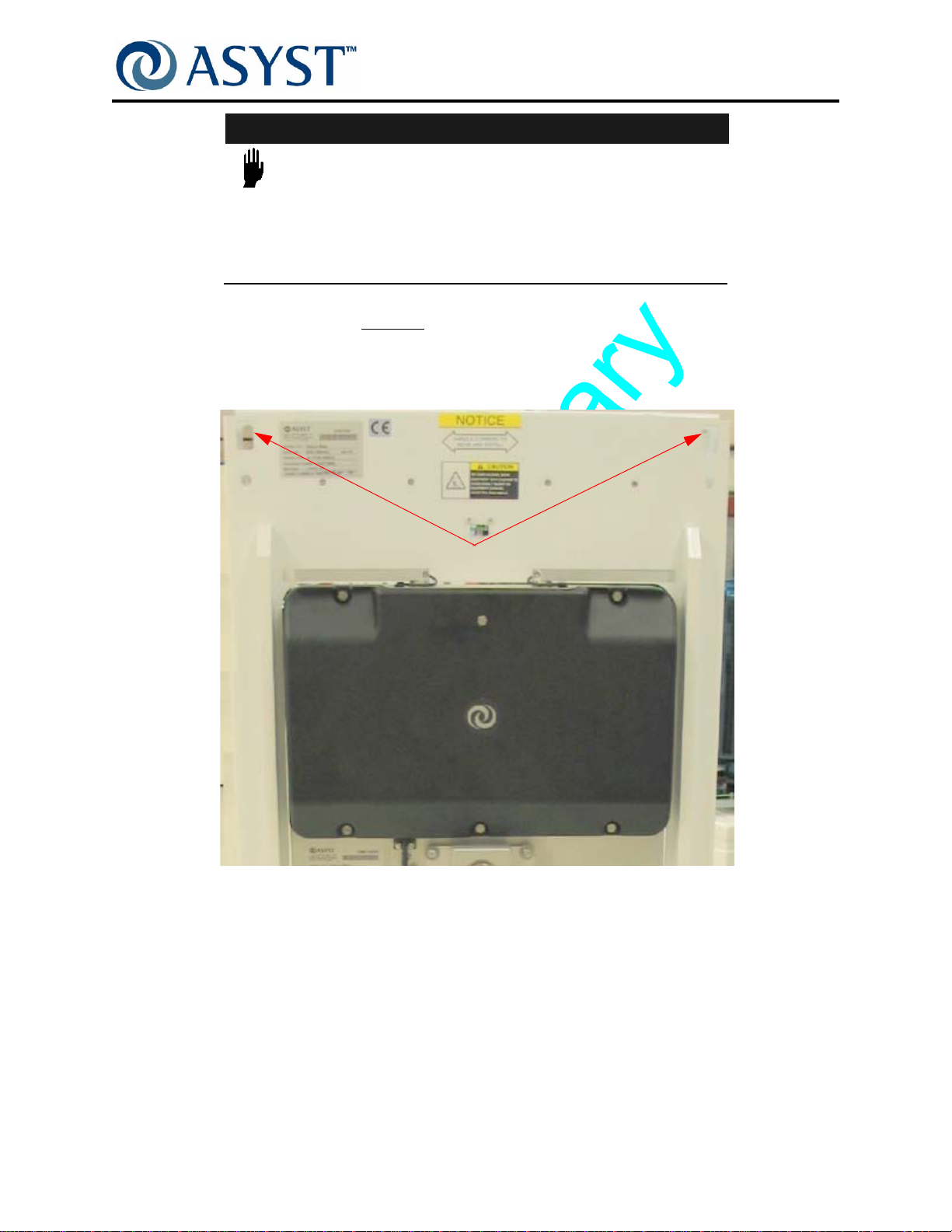
Safety Requirements
MECHANICAL HAZARD
FIMS DOOR MUST BE SECURED WITH THE SHIPPING BRACKET
EVERY TIME A COMPONENT OF THE VERTICAL/HORIZONTAL
D
SERIOUS INJURY.
WARNING
RIVE IS SERVICED. FAILURE TO DO SO MAY RESULT IN
Install shipping bracket (Asyst P/N 4003-0842-01)
to the FIMS Loadport Door and secure
with 8 screws to both the FIMS door and the BOLTS Frame. See Figure 3.
Screws
Screws
F
IGURE 3 Shipping Bracket Securing FIMS Door
Screws
If Vertical Drive Belt is disengaged or broken the Vertical Drive may free fall creating
pinch/crush hazards. All service procedures affecting the belt must use the FIMS door
shipping bracket (Asyst P/N 4003-0842-01) to assure the Vertical Drive is immobilized.
See Figure 4 on page 11 for affected areas.
Page 10 2000-6698-05 Draft Ax9

Falcon Technical Manual
Chapter 1: Safety Information
Safety Requirements
Operator Side
Host Tool Side
FIGURE 4 Areas of Pinch/Crush Hazard
During Installation
During installation, power to the Falcon must be off and the Host Tool in Lockout/Tagout
so there are no electrical (current) or mechanical hazards.
Draft Ax9 2000-6698-05 Page 11

Falcon Technical Manual
Chapter 1: Safety Information
Safety Requirements
Seismic
The position of the center of gravity (CG) will be shown in the forthcoming Outline
Drawing. Figure 5 shows seismic attachment points for the Falcon. Follow all installation
procedures to ensure compliance with SEMI S2: Safety Guidelines For Semiconductor
Manufacturing Equipment, Seismic Requirements.
Seismic
Attachment
Points
(top mount)
M8 Screw
Seismic
Attachment
Points
(regular)
M8 Screw
F
IGURE 5 Seismic Attachment Points
Ergonomic
A fully loaded FOUP exceeds recommended limits for handling by one operator. To
conform with SEMI S8, use of AGV, MGV, or OHS is recommended.
Page 12 2000-6698-05 Draft Ax9

Options
Wafer Mapper Option
See “ Wafer Mapper Assembly Option” on page 40 for details.
100-240VAC Option
See “ 100-240VAC Power Option” on page 41 for details
E84/PIO/ Interlock Option
See “ E84/PIO/Interlock Option” on page 43 for details.
Tilt and Go Wheels Option
See “ Tilt & Go Wheels Option” on page 44 for details.
Falcon Technical Manual
Chapter 1: Safety Information
Options
Draft Ax9 2000-6698-05 Page 13

Falcon Technical Manual
Chapter 1: Safety Information
Agency Compliance
Agency Compliance
FCC
Definition
Class A digital device
A digital device that is marketed for use in a commercial, industrial or business
environment, exclusive of a device which is marketed for use by the general public or is
intended to be used in the home.
Compliance
The Falcon with its integrated AdvanTag has been tested and found to comply with the
limits for a Class A digital device, pursuant to Part 15 of the FCC Rules. These limits are
designed to provide reasonable protection against harmful interference when the
equipment is operated in a commercial environment. This equipment generates, uses,
and can radiate radio frequency energy and, if not installed and used in accordance with
the instruction manual, may cause harmful interference to radio communications.
Operation of this equipment in a residential area is likely to cause harmful interference in
which case the user will be required to correct the interference at his/her own expense.
CAUTION
ANY CHANGES OR MODIFICATIONS TO THE FALCON
INTEGRATED RFID WITHOUT SPECIFIC WRITTEN APPROVAL
FROM ASYST TECHNOLOGIES WILL VOID FCC COMPLIANCE.
CE Mark
The Falcon with its integrated AdvanTag complies with the following directives:
• 2006/95/EC Low Voltage Directive
• 2004/108/EC EMC Directive
• 99/5/EC Radio & Telecommunication Terminal Equipment
• 98/37/EC Machinery Directive
Page 14 2000-6698-05 Draft Ax9

Safety Features
DC Voltage
The Falcon operating voltage is +24 VDC. This voltage is considered non-hazardous and
requires no mechanical power interlocks.
AC Option
If equipped with the 100-240VAC Option, the front cover has an electrical warning label
which alerts the user to an electrical hazard located behind the Front Cover. Shutdown
and lockout/tagout must be performed before opening the Front Cover. Also the front
cover is secured with a screw.
Pinch Hazard
During normal operation there is no pinch hazard.
During Service, a number of design points ensure that Service personnel in manual mode
are not exposed to hazards as described below:
Falcon Technical Manual
Chapter 1: Safety Information
Safety Features
Port Door
• Pinch hazards due to opening and closing of the Port Door.
The combination of the FOUP placement detection, and the FOUP-at-Port switch
provide an interlock to prevent a Port Door pinch hazard.
The FOUP must be in place on the FOUP advance and then must fully advance to
the port, sealing the port opening, before the Port Door will open during normal
operation in Auto Mode.
During Home Calibration, the Port Door , can move without a FOUP, but the motion
speed is slow and easily avoidable.
FOUP Advance
• Although there is no pinch hazard due to FOUP Advance motion, the following
safety feature is present:
Current Limiting Circuit limits the amount of force that can be exerted by the
FOUP Advance motion to a safe level. When FOUP comes in contact with an
object the FOUP Advance motion will stop.
Draft Ax9 2000-6698-05 Page 15

Falcon Technical Manual
Chapter 1: Safety Information
Moving and Handling
Moving and Handling
WARNING
TIP-OVER HAZARD
MOVING THE FALCON WITH A FOUP MOUNTED MAY CAUSE
THE FALCON TO TIP AND FALL OR OTHERWISE BECOME
UNSTABLE. INJURY AND/OR TOOL DAMAGE WILL OCCUR IF
FALCON FALLS.
NEVER move the Falcon with a FOUP mounted. Always remove the FOUP before
removing the Falcon from the Host tool, moving or installing the unit.
WARNING
TIP-OVER HAZARD
MOVING THE FALCON ON UNEVEN OR NON-LEVEL SURFACES
MAY CAUSE THE FALCON TO TIP AND FALL OR OTHERWISE
BECOME UNSTABLE. INJURY AND/OR TOOL DAMAGE WILL
OCCUR IF FALCON FALLS.
The Falcon may have wheels; therefore, once it is removed from the shipping container it
should be placed on a level surface. The extended portion of the shipping container base
enables the Falcon to be removed from the shipping container in its vertical position.
Store and Move the Falcon only in Vertical Position
Page 16 2000-6698-05 Draft Ax9
Falcon Technical Manual
Chapter 1: Safety Information
Moving and Handling
CAUTION
HANDLING OR BUMPING CERTAIN AREAS OF THE FALCON MAY
RESULT IN DAMAGE TO THE FOUP ADVANCE, DOOR DRIVE,
AND PORT DOOR ASSEMBLIES, AS WELL AS THE FRONT
COVER.
When moving the Falcon D
o NOT place hands on the top section of the FOUP advance
assembly, the door drive assembly, or by the wafer mapper assembly.
When moving the Falcon, PUSH from the Tool Side ONLY, placing hands on the corners
on the Tool SIde of the Falcon. See Figure 6.
Corners
F
IGURE 6 Tool Side Corners
The Falcon is designed to be pushed from the Tool Side only. Do not pull from the
Operator Side; do not push from the Operator Side except when mounting.
When moving the Falcon, use both hands to push at all times and push evenly. Keep all
four wheels on the ground at ALL times. Do not tilt or rock the Falcon while moving and
turning. Doing so may cause the Falcon to tip and fall.
Draft Ax9 2000-6698-05 Page 17
Falcon Technical Manual
Chapter 1: Safety Information
Labeling
Labeling
See Table 1 for a description of labels used on the Falcon. See Figure 7 on page 20,
Figure 8 on page 21 and Figure 9 on page 22 for typical label locations.
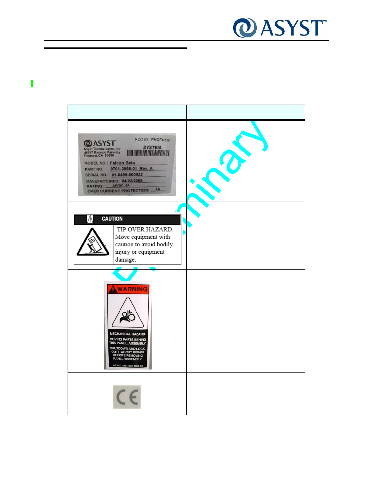
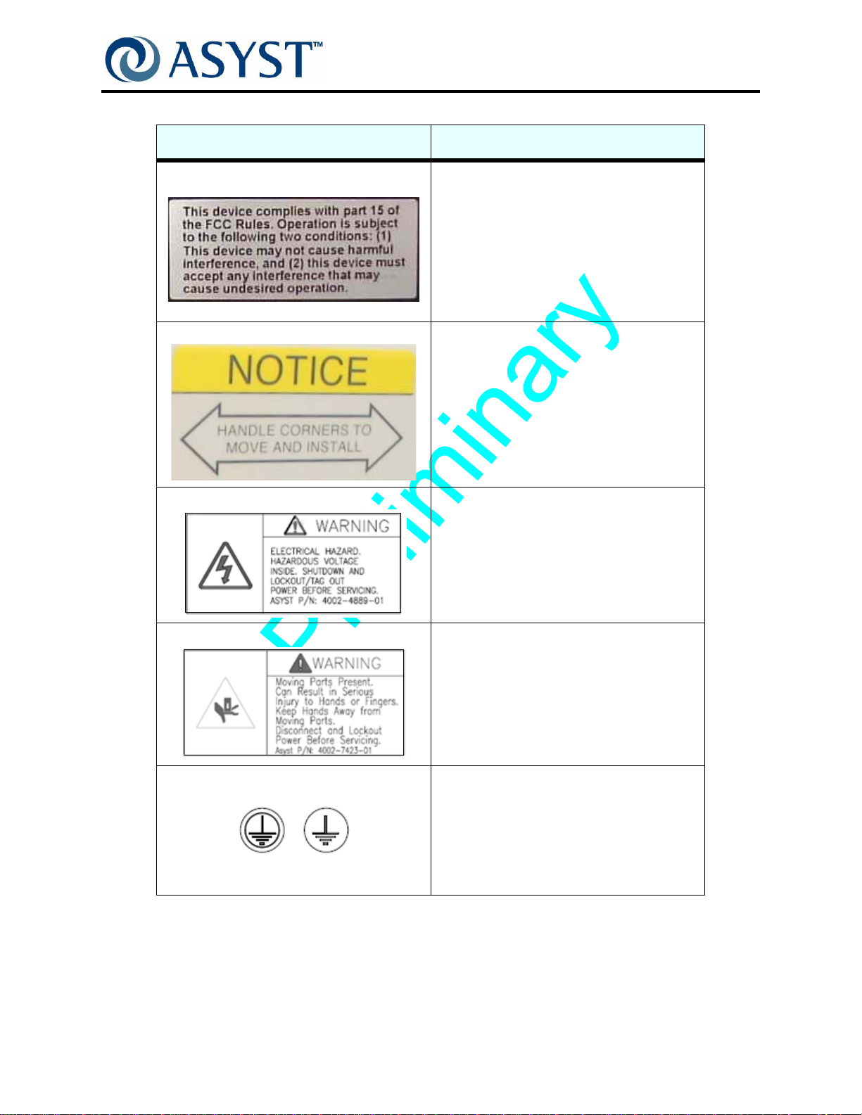
ABLE 1 List of Falcon Labels
T
Label Description/Location
Model/Serial Number Label The model and serial number label for the
Falcon provides FCC ID and unit specific
information required when contacting Asyst
Technologies for any matter concerning the
equipment.
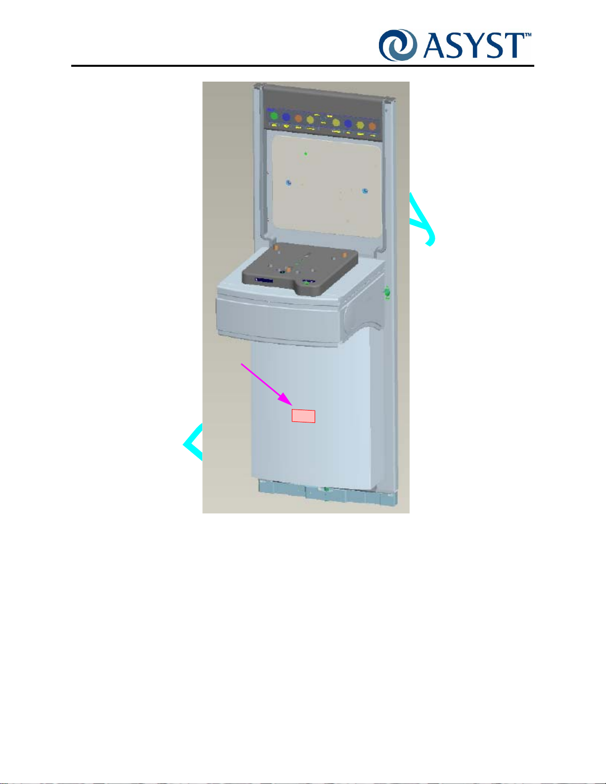
Tip Over Hazard The Tip Over Hazard label is an alert to move
the Falcon with caution. It is located above
the port door on the Host Tool side.
Mechanical Hazard The Mechanical Hazard label is an alert to
moving parts located behind the Cover with
the label. Shutdown and lockout/tagout must
be performed before opening the Cover.
Both Vertical and Horizontal styles are used.
CE Label This label identifies equipment that conforms
to testing and certification requirements of
the European Community.
Page 18 2000-6698-05 Draft Ax9
Falcon Technical Manual
Chapter 1: Safety Information
TABLE 1 List of Falcon Labels
Label Description/Location
FCC Label The presence of the FCC label indicates
compliance with FCC Rules and Regulations
as specified on the Label.
Handle Corners Label This label identifies where to handle
equipment.
Labeling
Electrical Hazard Label The Electrical Hazard label is an alert to
electrical hazard located behind the Front
Cover when the Falcon is configured with the
AC Power Option. Shutdown and
lockout/tagout must be performed before
opening the Front Cover.
FOR AC OPTION ONLY
Pinch Hazard Label The Pinch Hazard label is an alert to moving
parts located behind the Cover with the
label.Shutdown and lockout/tagout must be
performed before opening the Cover.
Ground Point Label The Ground Point Label indicates the Falcon
grounding point use to connect earth ground
wires from the Host tool.
AC
DC
Draft Ax9 2000-6698-05 Page 19

Falcon Technical Manual
Chapter 1: Safety Information
Labeling
Mechanical
Hazard
Label
Pinch
Hazard
Label
Belt
Cover
Ground
Label
FIGURE 7 Falcon Label Placement (Operator Side)
Page 20 2000-6698-05 Draft Ax9

Falcon Technical Manual
Chapter 1: Safety Information
Labeling
Name Plate
Label
FCC ID Label
FCC Label
CE Label
Handle
Corners
Label
Tip Over
Hazard
Label
Pinch
Hazard
Label
FIGURE 8 Falcon Label Placement (Host Tool Side)
Draft Ax9 2000-6698-05 Page 21
Falcon Technical Manual
Chapter 1: Safety Information
Labeling
Electrical
Hazard Label
FIGURE 9 Falcon with AC Option Only
Page 22 2000-6698-05 Draft Ax9
Chapter 2: Product Overview
This chapter describes the operation of Falcon and the interrelation of all of its
mechanical, electromechanical, and electronic subsystems.
The product overview is divided into the following sections:
“ Product Description” on page 24— an overall description of Falcon product.
“ Specifications” on page 27— Technical Data for Falcon.
Major Subassemblies with features, Options and Operational Descriptions:
• “ FIMS Door” on page 29
• “ Vertical-Horizontal Door Drive” on page 32
• “ FOUP Advance Subassembly” on page 34
• “ BOLTS Frame” on page 38
• “ Options” on page 40
• “ Operation Sequence”— describes Falcon’s typical operation sequence.
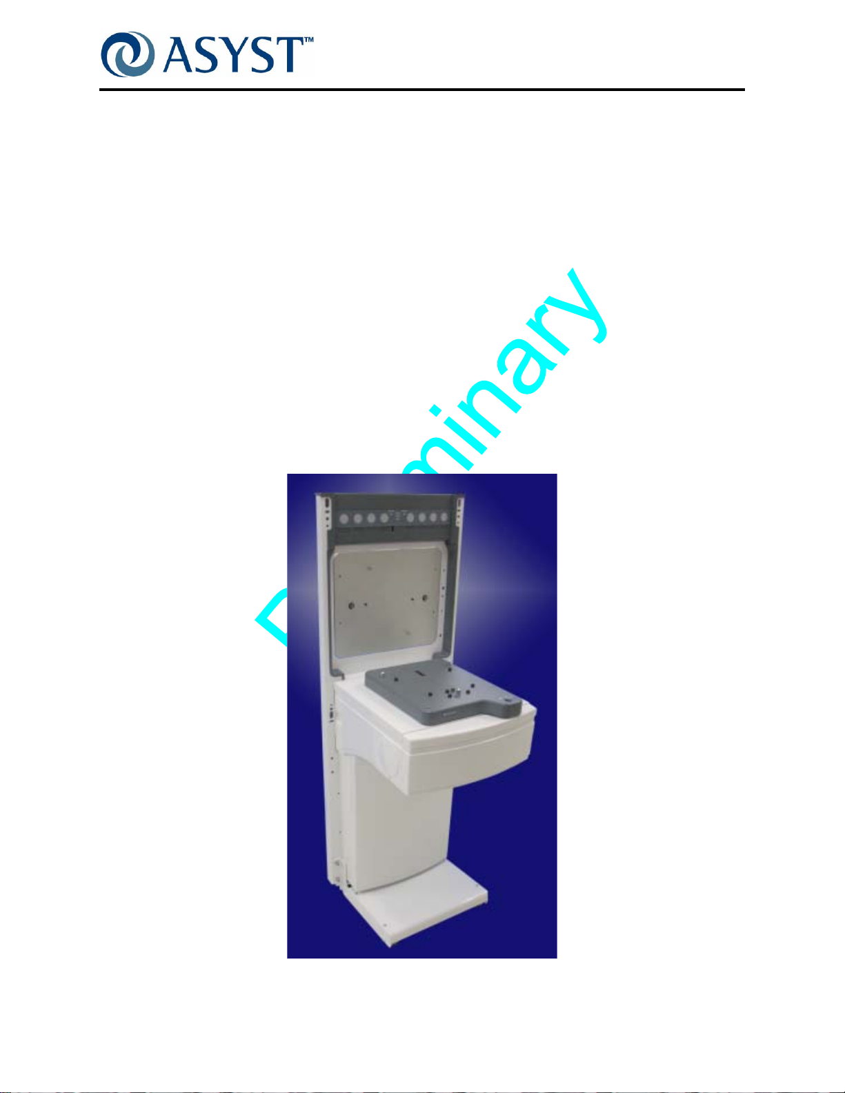
IGURE 10 Falcon Loadport
F
Draft Ax9 2000-6698-05 Page 23

Falcon Technical Manual
Chapter 2: Product Overview
Product Description
Product Description
The Falcon is an all-new loadport design based on Asyst’s many ye ars of experience with
loadports, incorporating input from a wide range of fabs & OEMs. This elegantly simple
design anticipates the customer demand for synergy between AMHS and EFEM requiring
seamless integration, faster hand-offs, more efficient buffering and improved productivity.
Asyst is the only loadport supplier with both EFEM and AMHS capability. Falcon has the
Best In Class performance for Speed and Clean liness. Asyst’s pate nted Latch key T wist &
Pull Technology to securely hold the FOUP Door during access, means no vacuum is
required.
The Falcon design improves reliability and speed of wafer handling, provides more robust
alignment stability, and reduces Preventive Maintenance requirements; All reducing the
overall cost of ownership. The modular design of the components shortens service times,
while eliminating most service alignments.
Falcon is a 300mm Loadport that maintains better than Class 1 environment for loading
and unloading (opening and closing) SEMI standard 300mm F OUPs. The Fro nt-Opening
Unified Pod (FOUP), designed for 25 wafer capacity, is a sealed carrier pod that provides
a sub-class 1 environment. Falcon is compatible with most SEMI standard compliant
FOUPs.
The Falcon interface to the Host tool complies with the SEMI 300mm Tool Loadport
Specification (E15.1). It is designed to directly mount onto a Host Tool through a SEMI
E63 (BOLTS) interface and can be quickly disconnected for ease of servicing.
A system of sensors and use of stepper motors ensure safe operation of Falcon,
preventing wafer breakage or errors in mechanical operation. Software provides for
integrated self-tests and diagnostics.
Page 24 2000-6698-05 Draft Ax9

Falcon Technical Manual
S
Chapter 2: Product Overview
Product Description
Major Components
This section describes the major components of the Falcon loadport, with operational
descriptions, subassemblies, and features.
Falcon Indicator
Display Lights
FIMS Port Door
FOUP Advance
Vertical/Horizontal Drive
(Under the Cover)
IGURE 11 Falcon Loadport
F
• “ FIMS Door” on page 29
• “ Vertical-Horizontal Door Drive” on page 32
• “ FOUP Advance Subassembly” on page 34
Static Entry Node
Link Manager
/CPU
Vert/Horizontal
Drive Belt Cover
with Fan
Falcon BOLTS
Interface
Host Tool BOLT
Mounting Plate
• “ BOLTS Frame” on page 38
Draft Ax9 2000-6698-05 Page 25
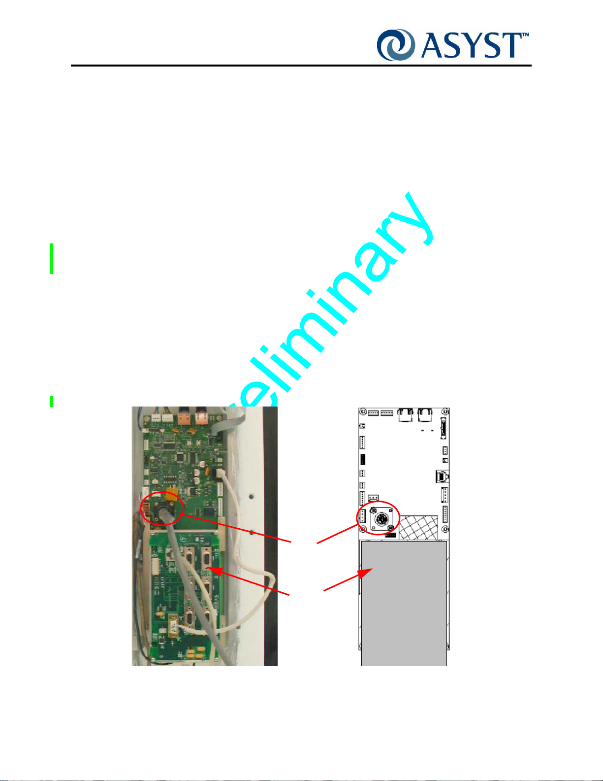
Falcon Technical Manual
Chapter 2: Product Overview
Product Description
Features
The following features contribute to Falcon’s easy adoption, ease of use and overall
product robustness.
• Protocol converters to emulate previous & competing loadports
• Browser configurable
• SW configurable indicator lights (no lenses)
• No internal alignment once installed
• Tilt-N-Go installation
• Integrated Features:
Manual Load/Unload Push Button Switch
AdvanTag RFID
• Integrated Options:
ABCD Mechanical Lockout Pin
ABCD Sensor
Wafer Mapping
Power
Falcon is powered by +24VDC (+10, -2%). The input power is applied through a CPC4
connector “+24VDC IN” (see Figure 12).
CPC4
Connector
Link
Manager
/CPU
F
IGURE 12 Static Entry Node PCB Assembly with Link Manager/CPU
Page 26 2000-6698-05 Draft Ax9

Specifications
TABLE 2 Falcon Product Specifications*
Wafer Size: 300mm
Height: 1351.1mm (53.19 in.)
Width: 470mm (18.5in.)
Depth: 485mm (19.1 in.) Note: from BOLTS Plane
Weight:
68Kg (150 lbs) with Tilt & Go Wheels installed
Mounting: Falcon is designed to directly mount onto a Host Tool having a SEMI E63
FOUP Load Height: Per SEMI Standards E15.1 and E63 ±10mm Height Adjustability on Host
Falcon Technical Manual
Chapter 2: Product Overview
Specifications
(BOLTS) interface.
tool
Contamination Control Wafer Environment Airborne
Particle Cleanliness
Fab Environment Airborne
Particle Cleanliness
Defect Density < 0.01 PWP @ 0.15 Particle Size
FOUP Compatibility The Falcon is designed to operate with SEMI E47 compliant wafer carriers.
Wafer Mapping Emitter Sensor - ± 1º beam angle Collimated IR LED
Receiver Sensor - Light-to-voltage photodiode with
Door Speed
(OPEN/CLOSE)
Power: Requirement from Host tool:
Communications: Serial RS-232C (ASCII or SECS 2), Ethernet (ASCII), Parallel is optional
8 Seconds Open with Wafer Mapping
8 Seconds Close with Wafer Mapping
24 VDC (
peak
100-240VAC Option, the customer provides 100-240VAC, 50/60Hz.,3.5A
AC Power module converts the power to the +24VDC (+10, -2%), 7A
required for Falcon operation.
+10, -2%) @ 7 amps
Class 1 per ISO 14644-1
Class 5 per ISO 14644-1
Falcon Power Consumption:
2 Amp standby (max)
5 Amp operating (max)
7 Amp peak (max)
Carrier Types 300mm 25-Wafer FOUP (Front Opening Unified Pods)
Vacuum None
Compressed Air None
Draft Ax9 2000-6698-05 Page 27

Falcon Technical Manual
Chapter 2: Product Overview
Specifications
TABLE 2 Falcon Product Specifications*
Noise 70-80dB RMS: Compliant to SEMI S8
Environmental: Operating Temperature 10 to 40° C.
Falcon complies with content of SEMI S2, SEMI S8, and CE Marking.
*Specifications subject to change without notice
Operating Humidity 10 to 75% non-condensing
Storage Temperature -10 to +55°C.
Storage Humidity 5 to 90% non-condensing
1351.1mm
580.1mm
470mm
F
IGURE 13 Falcon Basic Outline
485.0mm
3.0mm
BOLTS
Interface
Plate
For additional dimensions, interface points and datums see “ 2000-6803-01 Falcon
Outline Drawing” on page 284.
Page 28 2000-6698-05 Draft Ax9

FIMS Door
The Falcon Front-Opening Interface Mechanical Standard (FIMS) door is used to open a
25-wafer FOUP. Two latch keys located on the FIMS door rotate to horizontal to unlock
the FOUP door . Using Asyst’ s patented T wist & Pull techn ology, both latch keys retract at
the horizontal (unlocked) position to secure the FOUP door.
Falcon Technical Manual
Chapter 2: Product Overview
FIMS Door
Wafer Map
Emitter
Door
Node
PCB
Registration
Pins
F
IGURE 14 FIMS Door, Front View
Wafer Map
Receiver
Latch Key (2X)
FOUP-at
Port
Sensors
(2X)
Wafer
Mapper
(option)
Latch
Key
Home
Sensor
Latch
Key
Motor
Assy
IGURE 15 FIMS Door, Rear View (without Cover)
F
Draft Ax9 2000-6698-05 Page 29
FOUP Lock/
Unlock Latch
Key
Mechanism

Falcon Technical Manual
Chapter 2: Product Overview
FIMS Door
After the port door latch keys secure the FOUP door, it backs away from the FOUP, then
lowers until the FOUP opening is cleared. Once the port door is lowered, the wafers are
accessible for processing. For details on how the Port Door works in conjunction with the
FOUP Advance plate, see “ Operation Sequence” on page 45.
Features
Ball Joint with Clamping for Port Door Alignment
This feature enables roll, pitch and theta alignment of the port door with one fastener for
all three adjustments. This permits setup and alignment to be don e with 1 fixtu re and one
tool. The reduced part count reduces the potential for error. See Figure 16.
F
IGURE 16 Ball Joint Design
Simplified Twist and Pull Latch Key Drive
The Falcon design preserves Asyst’s proven and patented twist & pull latch key drive and
door retention with no vacuum system needed to secure a FOUP door to a FIMS door.
Each latch key provides 3-4 lbs of pulling force. This design uses a one piece cam drive
plate, guided by a latch key shaft to move the 2 individual latch key mechanisms. The
pull-in FOUP clamping feature is comprised on a spherical bushing and socket detent in
the cam drive plate. A compression spring provide the clamping force. The Falcon
latchkey are lubricated for the rate life of the unit and requires no preventive
maintenance. See Figure 17.
F
IGURE 17 Simplified Twist and Pull Latch Key Drive
Page 30 2000-6698-05 Draft Ax9

Falcon Technical Manual
Chapter 2: Product Overview
FIMS Door
Sensors
There are two FOUP-at-Port (F AP) Sensors th at will detect the presence of a FOUP door
when up against the FIMS door. Both FAP sensors detect the presence of a FOUP door
at the docked position.
Ground Path to FOUP Door
The Falcon provides a path to ground from the FOUP door through the port door latch
keys, when the FOUP door is removed from the FOUP.
Configurable Latch Key Over-Rotation
The Falcon rotates the latch key from the locked position at 90 degrees (FOUP Door
locked position) to the unlocked position of 0 degrees. Falcon can be configured for
over-rotation at the 90 degree position to 1,2, or 3 degrees over-rotate through the GUI
Interface. The factory default setting for over-rotate is 2 degrees.
Draft Ax9 2000-6698-05 Page 31
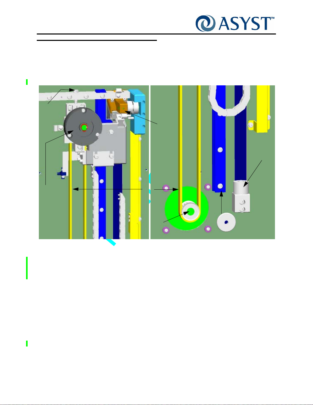
Falcon Technical Manual
Chapter 2: Product Overview
Vertical-Horizontal Door Drive
Vertical-Horizontal Door Drive
The vertical and horizontal drive (V/H Drive) has two functions: To open and close the
FOUP door. During opening of the FOUP door, the V/H Drive will move backward in
horizontal movement to clear to the BOLTS plate and downward to give to host tool
access to the wafers. See Figure 18.
Belt
Tension
Adjust
Door
Mount
Bumper
Upper
Pulley/
Encoder
Brake Assy
Top
During closing, the V/H Drive will move upward and in to close the FOUP.
When configured with the optional wafer mapper, mounted on the door module, the V/H
Drive makes 2 stops to allow for wafer mapping during open and/or close cycle.
The V/H Drive is designed to be maintenance free. There are no user serviceable
components and no alignments are necessary. Major modules (Motor, Upper
Pulley/Brake/Encoder Assembly , Belt) are designed for quick replacement if needed, with
no changes to alignment.
Features
Single Motor for Two Axes
Belt
Motor
Axle
IGURE 18 Vertical/Horizontal Door Drive Components
F
Guide Rail
Bottom
The design of the V ertical/Horizont al Drive Assembly incorpo rates a single stepper motor
and Belt Drive to perform both Vertical & Horizontal Door Motions. The Motor mounts
directly to the BOLTS plate frame so no machined brackets are required. The use of
Page 32 2000-6698-05 Draft Ax9

Falcon Technical Manual
Chapter 2: Product Overview
Vertical-Horizontal Door Drive
Direct stepper drive eliminates the need for a speed reduction system. The integrated
design means that fewer sensors, adjustments, and moving cables are required.
Upper Pulley/Brake/Encoder Assembly
The Upper Pulley/Brake/Encoder Assembly includes a 24V Brake used in the event of
power loss to stop Z Movement of the FIMS Door. The fail-safe Brake keeps the vertical
drive held in place when inactive or during loss of power.
The Encoder, part of the Upper Pulley Assembly, is used to give position feedback and
also to work with wafer mapper to detect wafer presence and slot positions in a FOUP.
There is no hard stop for homing the Vertical/Horizontal Drive, the encoder with home
sensor is used to determine home position. Home position of the V e rtical/Horizontal Drive
is at the top of the drive.
The Brake, part of the Upper Pulley Assembly, stops all movement of the
Vertical-Horizontal Door Drive:
• anytime power is cut
• at the end of motion (excluding Upper and Lower Mapping positions)
• whenever a following error is larger than its limit (Important during upward
movement to prevent the door from dropping)
Vertical/Horizont al Drive components (Motor , Upper Pulley/Brake wit h encoder , and home
sensors) all connect directly to the static entry node on the BOLTS frame.
Fan Assembly
The Fan Assembly is located on the bottom of the removable belt/drive cover. It provides
a continuous air flow for airborne particle control for the vertical/horizontal drive
mechanisms. This is done to insure no contamination to the Host Tool mini environment
by this mechanism.
Draft Ax9 2000-6698-05 Page 33

Falcon Technical Manual
e
Chapter 2: Product Overview
FOUP Advance Subassembly
FOUP Advance Subassembly
The FOUP Advance Module is a component of the Falcon loadport which is required to
position the FOUP on the loadport for processing by the Host Tool and AMHS system.
Kinematic Pins
Placement
Sensors
Hold
Down
Latch
Presence
Sensor
Emitter
InfoPads
AdvanTag
RFID
F
IGURE 19 FOUP Advance Plate without Cover
The FOUP Advance Module positions the carrier using kinematic pins in an orientation for
AMHS transfers, positions the FOUP in an orientation for opening the FOUP door and
positions the kinematic pins in an orientation using for wafer handling by a front end robot.
RFID Antenna
Manual
Load/Unload
Push Button Switch
FOUP
Advanc
Node
The FOUP Advance Module also provides a means of latching the carrier to prevent
removal of the carrier by operators with adequate holding force to allow door opening,
resisting operator applied forces, and a means of reading and/or writing to the carrier
RFID tag.
The K-Plate is supported by 2 linear rails that are attached to the FOUP Advance Base.
Falcon software uses two sensing systems, FOUP Placement and FOUP Presence, to
ensure that the FOUP advance will not operate unless the FOUP is properly positioned.
When the FOUP is placed on the Kinematic Pins of the FOUP Advance, the Presence
sensor detects the presence of the FOUP and the Placement sensors detect that the
FOUP has been properly placed.
Page 34 2000-6698-05 Draft Ax9

Falcon Technical Manual
Chapter 2: Product Overview
FOUP Advance Subassembly
The FOUP Advance controls horizontal movement of the FOUP and support plate. After
both the FOUP placement and presence sensors are triggered, the Active Pod Hold
Down (APHD) latches to hold the FOUP to the Kinematic Pins. This ensures the FOUP
can not be removed from the Kinematic Pins. The plate then moves towards the port door
to the configured FOUP docked position. The FIMS door moves to meet the FOUP door
at the Docked position. F AP sensors are actuated by th e FOUP door, confirming a FOUP
Door is present. The latchkeys then unlock the FOUP door and hold the FOUP door in
position on the port (FIMS) door.
Features
Torque Tube with Cantilevered Supports
• Provides major improvement in torsional rigidity/stability in the as-installed
condition
• Provides stable reference platform for the FOUP advance /K plate assembly
• Enables one time factory setup/alignment for critical K plate dimensions. No field
adjustment required.
Manual Load/Unload Push Button Switch
The FOUP Advance Plate features one push button switch that is end-user configured. It
is a Programmable Function Manual Push button with Indicator LEDs. See Figure 20.
F
IGURE 20 FOUP Advance Load/ Unload Push Button Switch
NOTE . . .
THE BUTTON MUST BE PROGRAMMED BY THE USER BEFORE SUBSEQUENT
ACTION IS PERFORMED BY THE FALCON AS A RESULT OF THE BUTTON EVENTS.
Draft Ax9 2000-6698-05 Page 35

Falcon Technical Manual
Chapter 2: Product Overview
FOUP Advance Subassembly
K-Plate Node PCB
The K-Plate Node PCB, located on the top of K-Plate, has two controllers, both which
communicate via CAN to the System Link Manager/CPU module.
Ti-DSP:
• Controls FOUP advance function using close loop Step motor and encoder.
• Controls FOUP Hold Down function using an open loop DC motor, and position
sensor.
• Provides approximately 30 general purposes I/Os.
• Monitor FOUP status through 7 on board sensors
• Communicates with system CPU via CAN
PIC-Controller:
• Controls RFID communication and RF power; and communicate with System
CPU via CAN.
Integrated AdvanTag Circuitry. The main component of the integrated AdvanTag
circuitry is a transmitter that generates radio waves through an antenna. This TIRIS
compatible low-frequency (134.2kHz), low-power RF energy is used to read from or write
to a transporter near the antenna. The 134.2kHz carrier from the RFID-ASIC is amplified
to the proper levels to drive the dual MOSFET power amplifier. This provides a 12Vp-p
low impedance drive to the antenna circuit. The antenna is a series resonant LC circuit
resonated at 134.2kHz to achieve maximum voltage on the antenna.
Cam Activated Pod Hold Down
The FOUP is held down and cannot be manually removed from the Falcon unless the
APHD is released.
– Very fast acting (0.40 seconds)
– No adjustments necessary
Sensors
FOUP Presence Sensors. One Emitter/Receiver pair located in the S tatus Display board
(emitter) and FOUP Advance Plate (receiver) to detect whether a FOUP is present on th e
Advance plate (the load/unload area).
FOUP Placement Sensors. There are 3 FOUP placement sensors, incorporated into the
FOUP Advance Plate; each sensor is located near a kinematic pin. The placement
sensors work in parallel to provide accurate detection of a FOUP that is correctly placed
on the FOUP Advance Plate/kinematic pins.
Page 36 2000-6698-05 Draft Ax9

Falcon Technical Manual
Chapter 2: Product Overview
FOUP Advance Subassembly
InfoPad Sensors. The Falcon provides for InfoPad sensors and/or a mechanical
interlock pin to be installed at four location on the FOUP Advance Plate. InfoPads
Sensors are used to distinguish between FOUP identities based on info plugs installed on
the underside of a FOUP. A mechanical lockout pin can be placed in any InfoPad position.
If the pin is placed in the "A" location, then a FOUP with the "A" location blocked cannot
be placed properly onto the loadport. This is to prevent wafers in certain FOUPs from
entering a process tool.
Draft Ax9 2000-6698-05 Page 37

Falcon Technical Manual
Chapter 2: Product Overview
BOLTS Frame
BOLTS Frame
The BOLTS frame is the structure to which main subassemblies are mounted. It also
provides the interface/mounting point for the Host Tool. In addition, the frame includes
several key electronic circuits as well as the status indicators.
Main Components
Light Display Node PCB
The Light Display Node PCB controls the indicator lights at the top of the Frame. The
Display PCB can only be accessed from the Operator side of Falcon. Figure 21 shows
the PCB (with the indicator light panel removed from the top of the Frame).
FOUP Presence Sensor
F
IGURE 21 Light Display Node PCB
The emitter of the FOUP Presence Sensor is located on the Display Node PCB. It works
in conjuction with the receiver located on the FOUP Advance assembly to detect whether
there is a FOUP on the FOUP Advance plate.
NOTE . . .
THE FOUP PRESENCE SWITCH DOES NOT INDICATE WHETHER THE FOUP IS
PLACED CORRECTLY ON THE PLATE, ONLY THAT THERE IS A OBJECT PRESENT
ON THE PLATE.
Excessive Wafer Protrusion Sensor
The Excessive Wafer Protrusion Sensor is located on the BOLTS frame assembly, this
interlock sensor detects whether a wafer is positioned too far out of the FOUP. If sensed,
all movement is halted to prevent damage to wafers and allow manual re-seating into the
FOUP.
The Excessive Wafer Protrusion sensor used on the Falcon is break-the-beam type
optical sensor It provides an off/on signal via the digital I/O and an interrupt to the
processor when actuated, V/H Door motion is stopped and a fatal error message is sent
to the Host (Tool).
Page 38 2000-6698-05 Draft Ax9

Falcon Technical Manual
Chapter 2: Product Overview
BOLTS Frame
Static Entry Node PCB
Located on the Operator side of the BOLTS Frame Assembly, the Static Entry Node
controls movement of the Horizontal/ Vertical Drive and FOUP Advance assemblies, and
is able to communicate via CAN to the Link Manager/CPU, the Door Node, and the FOUP
Advance Node.
The Static Entry Node contains circuitry that monitors voltage and current. If the applied
voltage becomes too low or too high the electronics will be shutdown until the correct
voltage level is restored. Over current (over load) protection device rating is 9 amp. To
recover the operation, power will have to be cycled off and then on again.
CPC4 Power
Connector
Link
Manager
/CPU
F
IGURE 22 Static Entry Node PCB
ABLE 3 Static Entry Node Connections
T
SEN Connector Goes To
J1 V/H Motor Encoder J1 Ethernet
J3 V/H Drive Brake Comm1 RS232 Serial
J9 RJ45 cable goes to -------> J10 DB9
J22 Main Power In
Link
Manager/CPU
J23 V/H Motor
J25 Fan
J27 V/H Home Sensor
J36 Excessive Protrusion Sensor
Draft Ax9 2000-6698-05 Page 39

Falcon Technical Manual
Chapter 2: Product Overview
Options
Options
Current options available for the Falcon are the Wafer Mapper, the 100-240VAC Power
Option, the E84/PIO/Interlock Option and the Tilt & Go Wheel option.
Wafer Mapper Assembly Option
An optional wafer map system can be attached to the FIMS door, that consists of two
arms, with sensors, operating during the vertical movement of the port door to determine
the position of wafers and detect cross-slotting or double-slotting of wafers within a
FOUP. See Figure 23.
IGURE 23 Wafer Mapper Uninstalled
F
The wafer mapper assembly with protrusion module is comprised of a light source and a
receiver. The light source/receiver pair is for detecting wafer presence, empty slots,
cross-slotted and double-slotted wafers within the FOUP. This wafer map data is
transmitted to the host tool. Two stepper motors are used to deploy and retract the arms.
The Falcon wafer mapper is designed to be maintenance free. There are no user
serviceable components and no alignments are necessary.
Page 40 2000-6698-05 Draft Ax9

Falcon Technical Manual
Chapter 2: Product Overview
100-240VAC Power Option
Typically th e Falcon is powered by +24VDC ( +10, -2%) provided by the Customer, via the
Host Tool. Falcon loadports configured with the 100-240VAC 50/60 Hz, 3.5A Option,
permit the customer to provide AC power to an AC Power Supply, within the Falcon, that
converts the power to the +24VDC (+10, -2%), 7A required for Falcon operation. See
Figure 24 for main view of components, see Figure 25 for tool side view and see Figure
26 on page 42 for wiring diagram.
Options
Belt Cover/Fan
Assembly
100-240VAC
Power Supply
IGURE 24 Components of the 100-240VAC Option
F
Static Entry
Node
24VDC
Power Input
Link Manager
/CPU
100-240VAC
Power Input
100-240VAC
Power Input
F
IGURE 25 Tool Side View
Draft Ax9 2000-6698-05 Page 41
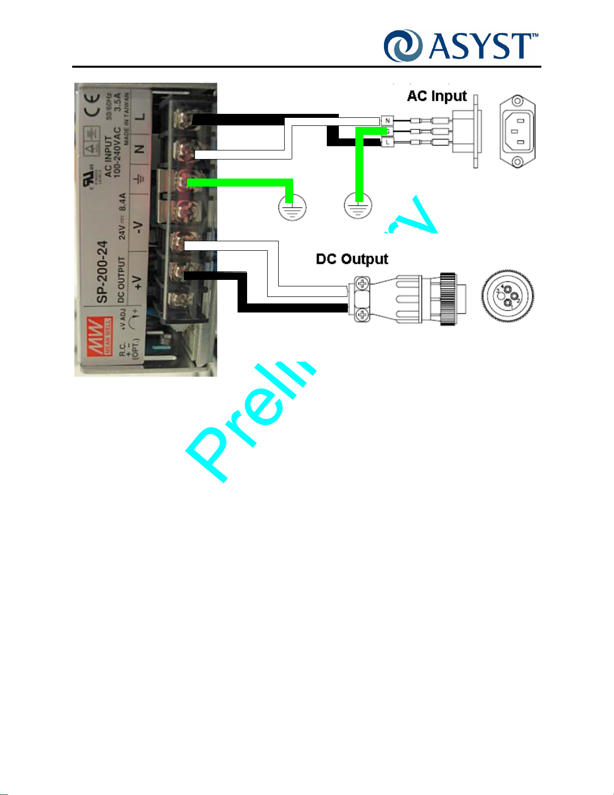
Falcon Technical Manual
Chapter 2: Product Overview
Options
Load
Neutral
Ground
Pin 4
Pin 1
FIGURE 26 Wiring for the AC Option
Ground
Page 42 2000-6698-05 Draft Ax9

Falcon Technical Manual
Chapter 2: Product Overview
E84/PIO/Interlock Option
The E84/PIO/Interlock Option provides communications interface with a variety of FOUP
delivery systems including AGV, AMHS, or process tools.
The E84/PIO/Interlock Option provides several functions for the Falcon loadport:
• Provides E84 interface for communication with AMHS/AGV systems for FOUP
delivery.
• Provides PIO interface for communication with process tools for door close/open
operation.
• Provides an interlock to disable loadport operation.
Components
The E84/PIO/Interlock Option consist of the E84 Node PCB and connecting cables.
Options
J12
RJ45
J6 Receptacle
D-Sub
25 Pin
J10 Receptacle
D-Sub
25 Pin
J15 Plug
D-Sub
15 Pin
J13 RJ45
J14
J16
IGURE 27 E84 Board
F
Draft Ax9 2000-6698-05 Page 43
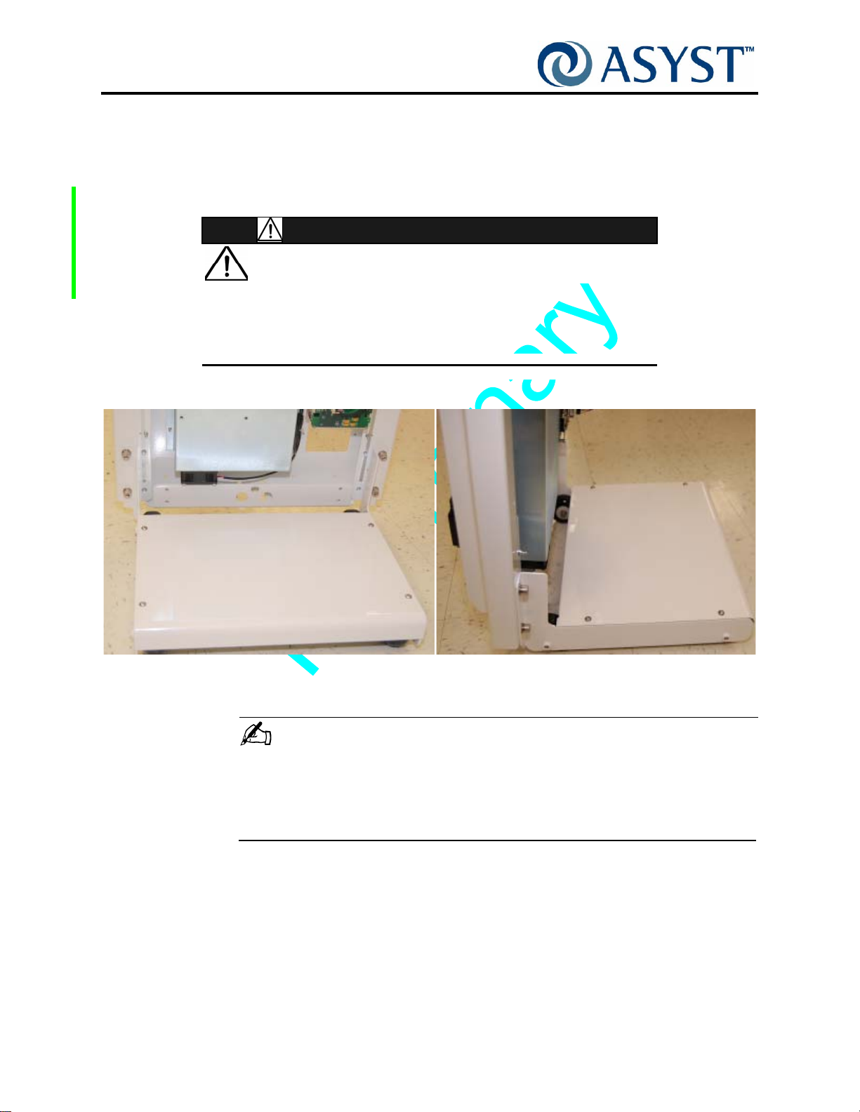
Falcon Technical Manual
Chapter 2: Product Overview
Options
Tilt & Go Wheels Option
The Tilt & Go wheels option allows a single operator to assemble and align the Falcon to
the Host tool, as well as remove the Falcon from the Host tool. Also, one operator can
move the Falcon to various parts of a fab (e.g., from tool to tool, to a repair area). See
Figure 28 on page 44.
GENERAL HAZARD
FOR ONE PERSON REMOVAL FALCON MUST HAVE A BASE
WHEEL ASSEMBLY ATTACHED BEFORE REMOVING THE
F
ALCON FROM THE HOST TOOL. THE WHEEL ASSEMBLY MAY
HAVE BEEN REMOVED AFTER INSTALLATION.
CAUTION
IGURE 28 Falcon Tilt & Go Wheels
F
NOTE . . .
WITHOUT THE TILT AND GO WHEEL OPTION THE FALCON MUST BE MOVED
USING A TWO PERSON LIFT, TAKING CARE TO OBSERVE THE MOVING AND
HANDLING REQUIREMENTS SPELLED OUT IN THIS CHAPTER. SEE “ Moving and
Handling” on page 16.
Page 44 2000-6698-05 Draft Ax9

Operation Sequence
Step 1 Undocked (Home) Position
The operating sequence for Falcon always begins from the undocked (Home) position:
• Vertical Drive is at Home position; Door is at Closed position
• FOUP Advance Drive is at Undocked position
• Latch Keys are in Vertical position
• Wafer Map Arms are retracted
• Active Pod Hold Down is in Open position
Step 2 Place FOUP on FOUP Advance Plate
1. FOUP is properly placed onto the kinematic pins located on the FOUP advance plate.
FOUP Presence sensors and FOUP Placement sensors are activated.
Falcon Technical Manual
Chapter 2: Product Overview
Operation Sequence
2. Falcon reports to Host that the FOUP has arrived.
Step 3 Advance FOUP to Port Door
1. Host sends an Open command to open the FOUP.
2. The FOUP Advance Module latches the carrier to prevent removal of the carrier while
the door is open.
3. Integrated AdvanTag reads and/or writes to the carrier RFID tag as initiated by the
Host.
4. The FOUP Advance moves the FOUP towards the FIMS door to the configured
FOUP docked position.
5. The FIMS door moves to meet the FOUP door at the Docked position.
6. FAP sensors are actuated by the FOUP door confirming a FOUP Door is present.
Step 4 Open and Lower the Port and FOUP Doors
1. Latch Keys unlock the FOUP door and hold the FOUP door in position on the port
(FIMS) door.
2. FIMS door with FOUP door are moved horizontally and vertically away from the port
to clear the opening.
3. With Wafer Map Option present, vertical drive moves to Mapper Upper position.
4. With Wafer Map Option present, Wafer Map Light Source (IR LED) activates.
5. With Wafer Map Option present, Wafer Mapper arms extend, and the Wafer Map
system activates.
Draft Ax9 2000-6698-05 Page 45
 Loading...