

AdvanTag 9180
Technical Manual
Rev. Bx1 Date: 11/04/2008
P/N: 2000-6631-05
Copyright © 2008 Asyst Technologies, Inc.,
All rights reserved.

AdvanTag 9180 Technical Manual
Page ii 2000-6631-05 Draft Rev. Bx1

Disclaimers
This manual may not be reproduced, either wholly or in part, for any reason whatsoever, without prior written permission
from Asyst Technologies, Inc. (“Asyst”). Material contained in this manual is provided for informational purposes and is
subject to change without notice.
If this manual is marked “Preliminary” or “Draft,” then Asyst has not yet released a final version of the manual and the
manual is likely to be incomplete and will be revised. Contact Asyst at the address below to obtain a final copy of the
manual.
Manual Information
ECN: unreleased
Part Number: 2000-6631-05
Date: 11/04/2008
Release: Rev. Bx1
Asyst Technologies, Inc.
46897 Bayside Parkway
Fremont, California 94538
Telephone: (510) 661-5000
FAX: (510) 661-5166
Technical Support: 1-800-342-SMIF
AdvanTag 9180 Technical Manual
Disclaimers
Trademarks
Asyst, the Asyst logo(s), FLUOROTRAC, KPOD, ADU and MANUFACTURING CONNECTIVITY are registered trademarks
® of Asyst Technologies, Inc.
VERSAPORT, PLUS, INX, ADVANTAG, LINK MANAGER, SMART-TAG, SMART-STATION, SMART-STORAGE,
SMART-TRAVELER, SMART-COMM, AXYS, FASTRACK, FASTMOVE, FASTLOAD, FASTORE are trademarks
Asyst Technologies, Inc.
All other product and company names mentioned herein may be trademarks and/or service marks of their respective
owners.
Equipment Modification
Any change, alteration, or modification to this equipment, as well as use of this equipment in a manner inconsistent with its
intended use will void this equipment’s warranty and may render this equipment unsafe for use or unfit for its intended
purposes.
Training and Languages
User training for equipment operation and maintenance is conducted in English. Translators are available on an as needed
basis. English versions of the manuals and other technical materials are provided and reviewed during the training. Please
contact the Asyst Training department or http://www.asyst.com for the training schedule and signup requirements.
Warranty
For warranty information, see Asyst’s Standard Terms and Conditions.
TM
of
Draft Rev. Bx1 2000-6631-05 Page iii

AdvanTag 9180 Technical Manual
Reader Comments
Reader Comments
We welcome your comments regarding this manual. Your comments and suggestions
help us to improve our publications.
Please send comments and suggestions to:
Asyst Technologies, Inc.
Technical Publications Manager
46897 Bayside Parkway
Fremont CA 94538
Or fax: Attention—Tech Pubs Manager at 1-510-661-5157
Or email: TechPubs@asyst.com
Include the following:
Name:
Company:
Contact Phone # (in case we have questions):
Email:
Document Information (Name of document, Part Number, Revision):
Location of comment (page number or other reference):
Comments: (The more specific the comments, the more useful they are to us.)
Thank you for helping to improve the manuals and to maintain accuracy.
Page iv 2000-6631-05 Draft Rev. Bx1

Acronym List
AMHS Automated Material Handling System
ASCII American Standard Coding for Information Interchange
ATR AdvanTag Reader
CIDRW Carrier IDentification Read Write
CIM Computer-Integrated Manufacturing
EMF Electromagnetic Field
EMI Electromagnetic Interference
EMO Emergency (Machine) Off
ESD Electrostatic Discharge
FOUP Front Opening Unified Pod
HSMS High Speed Messaging System
LSB Least Significant Bit
MIDS Material IDentification Station
MSB Most Significant Bit
OEM Original Equipment Manufacturer
PN or P/N Part Number
RFID Radio Frequency IDentification
SECS Semiconductor Equipment Communication Standard
SEMI Semiconductor Equipment and Materials International
SMIF Standard Mechanical Interface
Draft Rev. Bx1 2000-6631-05 Page v

AdvanTag 9180 Technical Manual
Page vi 2000-6631-05 Draft Rev. Bx1

Revision History
Date Author Version Revision Information
6/3/2008 Catherine Day A Initial Release - ECN 09697
11/4/2008 Catherine Day Bx1 Made changes to Environmental, Antenna Requirements and
CE Mark Compliance in Chapter 1, per T. Vang. Clarified
Product Description in Chapter 2 per T. Vang.
Draft Rev. Bx1 2000-6631-05 Page vii

AdvanTag 9180 Technical Manual
Page viii 2000-6631-05 Draft Rev. Bx1

AdvanTag 9180 Technical Manual
Table of Contents
Disclaimers . . . . . . . . . . . . . . . . . . . . . . . . . . . . . . . . . . . . . . . . . . . . . . . . . . . . . . iii
Manual Information . . . . . . . . . . . . . . . . . . . . . . . . . . . . . . . . . . . . . . . . . . . . . . . .iii
Trademarks . . . . . . . . . . . . . . . . . . . . . . . . . . . . . . . . . . . . . . . . . . . . . . . . . . . . . .iii
Equipment Modification. . . . . . . . . . . . . . . . . . . . . . . . . . . . . . . . . . . . . . . . . . . . . iii
Training and Languages . . . . . . . . . . . . . . . . . . . . . . . . . . . . . . . . . . . . . . . . . . . . iii
Warranty . . . . . . . . . . . . . . . . . . . . . . . . . . . . . . . . . . . . . . . . . . . . . . . . . . . . . . . . iii
Reader Comments . . . . . . . . . . . . . . . . . . . . . . . . . . . . . . . . . . . . . . . . . . . . . . . .iv
Acronym List. . . . . . . . . . . . . . . . . . . . . . . . . . . . . . . . . . . . . . . . . . . . . . .v
Revision History . . . . . . . . . . . . . . . . . . . . . . . . . . . . . . . . . . . . . . . . . . . vii
Table of Contents . . . . . . . . . . . . . . . . . . . . . . . . . . . . . . . . . . . . . . . . . . ix
List of Figures. . . . . . . . . . . . . . . . . . . . . . . . . . . . . . . . . . . . . . . . . . . . xiii
List of Tables . . . . . . . . . . . . . . . . . . . . . . . . . . . . . . . . . . . . . . . . . . . . .xv
Preface . . . . . . . . . . . . . . . . . . . . . . . . . . . . . . . . . . . . . . . . . . . . . . . . . . 1
Purpose and Audience . . . . . . . . . . . . . . . . . . . . . . . . . . . . . . . . . . . . . . . . . . . . . 1
About this Manual . . . . . . . . . . . . . . . . . . . . . . . . . . . . . . . . . . . . . . . . . . . . . . . . . 1
References . . . . . . . . . . . . . . . . . . . . . . . . . . . . . . . . . . . . . . . . . . . . . . . . . . . . . . 1
Conventions . . . . . . . . . . . . . . . . . . . . . . . . . . . . . . . . . . . . . . . . . . . . . . . . . . . . . 2
Safety Tags. . . . . . . . . . . . . . . . . . . . . . . . . . . . . . . . . . . . . . . . . . . . . . . . . . . . . . 2
Chapter 1: General Information. . . . . . . . . . . . . . . . . . . . . . . . . . . . . . . 5
Specifications . . . . . . . . . . . . . . . . . . . . . . . . . . . . . . . . . . . . . . . . . . . . . . . . . . . . 5
Outline Drawing. . . . . . . . . . . . . . . . . . . . . . . . . . . . . . . . . . . . . . . . . . . . . . . . . . . 6
Safety . . . . . . . . . . . . . . . . . . . . . . . . . . . . . . . . . . . . . . . . . . . . . . . . . . . . . . . . . . 7
ESD / EMI Precautions . . . . . . . . . . . . . . . . . . . . . . . . . . . . . . . . . . . . . . . . . . 7
Electrical Power/Input Power Requirements . . . . . . . . . . . . . . . . . . . . . . . . . . 7
Environmental . . . . . . . . . . . . . . . . . . . . . . . . . . . . . . . . . . . . . . . . . . . . . . . . . 7
Warranty and Liability . . . . . . . . . . . . . . . . . . . . . . . . . . . . . . . . . . . . . . . . . . . 8
FCC Compliance. . . . . . . . . . . . . . . . . . . . . . . . . . . . . . . . . . . . . . . . . . . . . . . . . . 8
CE Mark Compliance . . . . . . . . . . . . . . . . . . . . . . . . . . . . . . . . . . . . . . . . . . . . . . 8
Labeling. . . . . . . . . . . . . . . . . . . . . . . . . . . . . . . . . . . . . . . . . . . . . . . . . . . . . . . . . 9
Location of Labels used on the AdvanTag . . . . . . . . . . . . . . . . . . . . . . . . . . 10
Draft Rev. Bx1 2000-6631-05 Page ix

AdvanTag 9180 Technical Manual
Chapter 2: Theory of Operation. . . . . . . . . . . . . . . . . . . . . . . . . . . . . . 11
Product Description. . . . . . . . . . . . . . . . . . . . . . . . . . . . . . . . . . . . . . . . . . . . . . . 11
TargetID. . . . . . . . . . . . . . . . . . . . . . . . . . . . . . . . . . . . . . . . . . . . . . . . . . . . . 12
Using HSMS Protocol as Host . . . . . . . . . . . . . . . . . . . . . . . . . . . . . . . . . . . . . . 13
Message Format and Translation . . . . . . . . . . . . . . . . . . . . . . . . . . . . . . . . . 13
Messages Supported. . . . . . . . . . . . . . . . . . . . . . . . . . . . . . . . . . . . . . . . . . . 14
Specifications. . . . . . . . . . . . . . . . . . . . . . . . . . . . . . . . . . . . . . . . . . . . . . . . . 14
Integration of Parts . . . . . . . . . . . . . . . . . . . . . . . . . . . . . . . . . . . . . . . . . . . . . . . 15
Mounting . . . . . . . . . . . . . . . . . . . . . . . . . . . . . . . . . . . . . . . . . . . . . . . . . . . . 15
Ports . . . . . . . . . . . . . . . . . . . . . . . . . . . . . . . . . . . . . . . . . . . . . . . . . . . . . . . 15
Data Storage—AdvanTag Reader . . . . . . . . . . . . . . . . . . . . . . . . . . . . . . . . . . . 16
Memory . . . . . . . . . . . . . . . . . . . . . . . . . . . . . . . . . . . . . . . . . . . . . . . . . . . . . 16
MicroTags . . . . . . . . . . . . . . . . . . . . . . . . . . . . . . . . . . . . . . . . . . . . . . . . . . . 16
Default Values of R/W ATTRIBUTES . . . . . . . . . . . . . . . . . . . . . . . . . . . . . . 21
Interfaces . . . . . . . . . . . . . . . . . . . . . . . . . . . . . . . . . . . . . . . . . . . . . . . . . . . . . . 26
LEDs . . . . . . . . . . . . . . . . . . . . . . . . . . . . . . . . . . . . . . . . . . . . . . . . . . . . . . . 26
Connectors . . . . . . . . . . . . . . . . . . . . . . . . . . . . . . . . . . . . . . . . . . . . . . . . . . 27
Buttons/Switches . . . . . . . . . . . . . . . . . . . . . . . . . . . . . . . . . . . . . . . . . . . . . . 30
Communications . . . . . . . . . . . . . . . . . . . . . . . . . . . . . . . . . . . . . . . . . . . . . . . . . 31
To Host . . . . . . . . . . . . . . . . . . . . . . . . . . . . . . . . . . . . . . . . . . . . . . . . . . . . . 31
Read Range. . . . . . . . . . . . . . . . . . . . . . . . . . . . . . . . . . . . . . . . . . . . . . . . . . 31
SECS. . . . . . . . . . . . . . . . . . . . . . . . . . . . . . . . . . . . . . . . . . . . . . . . . . . . . . . 31
Serial Communications Interface. . . . . . . . . . . . . . . . . . . . . . . . . . . . . . . . . . 31
Ethernet Communications . . . . . . . . . . . . . . . . . . . . . . . . . . . . . . . . . . . . . . . 31
Software . . . . . . . . . . . . . . . . . . . . . . . . . . . . . . . . . . . . . . . . . . . . . . . . . . . . . . . 32
Web Configurator . . . . . . . . . . . . . . . . . . . . . . . . . . . . . . . . . . . . . . . . . . . . . . . . 33
HSMS Configuration . . . . . . . . . . . . . . . . . . . . . . . . . . . . . . . . . . . . . . . . . . . 33
Read-Write Radio . . . . . . . . . . . . . . . . . . . . . . . . . . . . . . . . . . . . . . . . . . . . . 35
Antenna Performance . . . . . . . . . . . . . . . . . . . . . . . . . . . . . . . . . . . . . . . . . . . . . 38
Chapter 3: Troubleshooting. . . . . . . . . . . . . . . . . . . . . . . . . . . . . . . . . 41
Troubleshooting Chart. . . . . . . . . . . . . . . . . . . . . . . . . . . . . . . . . . . . . . . . . . . . . 41
Troubleshooting for RS232 . . . . . . . . . . . . . . . . . . . . . . . . . . . . . . . . . . . . . . . . . 42
Troubleshooting for HSMS ATR9180 . . . . . . . . . . . . . . . . . . . . . . . . . . . . . . . . . 43
Troubleshooting guide for the 9701-3651-01 ATR 9180 . . . . . . . . . . . . . . . . 43
For Additional Troubleshooting Assistance. . . . . . . . . . . . . . . . . . . . . . . . . . . . . 45
Appendix A: Functional Test Log . . . . . . . . . . . . . . . . . . . . . . . . . . . . 47
Page x 2000-6631-05 Draft Rev. Bx1

AdvanTag 9180 Technical Manual
Cycle Testing . . . . . . . . . . . . . . . . . . . . . . . . . . . . . . . . . . . . . . . . . . . . . . . . . 51
Appendix B: HSMS Test Log. . . . . . . . . . . . . . . . . . . . . . . . . . . . . . . . 53
Sample Log . . . . . . . . . . . . . . . . . . . . . . . . . . . . . . . . . . . . . . . . . . . . . . . . . . . . . 53
Index. . . . . . . . . . . . . . . . . . . . . . . . . . . . . . . . . . . . . . . . . . . . . . . . . . . 73
Draft Rev. Bx1 2000-6631-05 Page xi

AdvanTag 9180 Technical Manual
Page xii 2000-6631-05 Draft Rev. Bx1

AdvanTag 9180 Technical Manual
List of Figures
Figure 1 Outline Drawing, AdvanTag 9180 Reader . . . . . . . . . . . . . . . . . . . . . . . 6
Figure 2 Label Locations, AdvanTag 9180 Reader . . . . . . . . . . . . . . . . . . . . . . 10
Figure 3 AdvanTag 9180 Top Views. . . . . . . . . . . . . . . . . . . . . . . . . . . . . . . . . . .11
Figure 4 AdvanTag 9180 Reader LEDs . . . . . . . . . . . . . . . . . . . . . . . . . . . . . . . 26
Figure 5 Locating the Reset Switch . . . . . . . . . . . . . . . . . . . . . . . . . . . . . . . . . . 30
Figure 6 ATR 9180 Web Interface - Home Page . . . . . . . . . . . . . . . . . . . . . . . . 33
Figure 7 Web Interface - Configuration Page. . . . . . . . . . . . . . . . . . . . . . . . . . . 34
Figure 8 Web Interface - Read Write Page . . . . . . . . . . . . . . . . . . . . . . . . . . . . 35
Figure 9 Read MID Response . . . . . . . . . . . . . . . . . . . . . . . . . . . . . . . . . . . . . . 35
Figure 10 Read Data Response. . . . . . . . . . . . . . . . . . . . . . . . . . . . . . . . . . . . . . 36
Figure 11 Write MID Response . . . . . . . . . . . . . . . . . . . . . . . . . . . . . . . . . . . . . . 36
Figure 12 Write Data Response . . . . . . . . . . . . . . . . . . . . . . . . . . . . . . . . . . . . . . 37
Figure 13 Vertical Read Range . . . . . . . . . . . . . . . . . . . . . . . . . . . . . . . . . . . . . . 39
Figure 14 Horizontal Read Range . . . . . . . . . . . . . . . . . . . . . . . . . . . . . . . . . . . . 40
Draft Rev. Bx1 2000-6631-05 Page xiii

AdvanTag 9180 Technical Manual
Page xiv 2000-6631-05 Draft Rev. Bx1

AdvanTag 9180 Technical Manual
List of Tables
Table 1 AdvanTag 9180 Specifications . . . . . . . . . . . . . . . . . . . . . . . . . . . . . . . . 5
Table 2 Labels. . . . . . . . . . . . . . . . . . . . . . . . . . . . . . . . . . . . . . . . . . . . . . . . . . . 9
Table 3 ATR9180 Configuration for Dual-Sensor Operation. . . . . . . . . . . . . . . 19
Table 4 ATR9180 Configuration for Event-Change operation. . . . . . . . . . . . . . 20
Table 5 Attribute Values (ECID and SVID) . . . . . . . . . . . . . . . . . . . . . . . . . . . . 21
Table 6 Power Cable Pin Outs . . . . . . . . . . . . . . . . . . . . . . . . . . . . . . . . . . . . . 27
Table 7 Serial Port Pin Usage. . . . . . . . . . . . . . . . . . . . . . . . . . . . . . . . . . . . . . 28
Table 8 ATR 9180 Common Errors and Solutions . . . . . . . . . . . . . . . . . . . . . . 41
Draft Rev. Bx1 2000-6631-05 Page xv

AdvanTag 9180 Technical Manual
Page xvi 2000-6631-05 Draft Rev. Bx1

Purpose and Audience
This manual describes the Asyst AdvanTag 9180 Reader, also referred to as the ATR
9180, which is part of Asyst’s radio-frequency auto ID system, AdvanTag. The AdvanTag
Reader is an Asyst OEM, SEMI-standard device that reads and writes to tags embedded
in wafer cassettes, pods, FOUPs, reticle boxes, and other assets.
This document is intended for user of the AdvanTag system and the ATR 9180. Service is
not applicable to the ATR 9180; see “Servicing” on page 7.
About this Manual
The AdvanTag 9180 Reader Manual is organized as follows:
Chapter 1, “General Information” on page 5, provides specifications and describes safety
considerations and labeling for the AdvanTag 9180 Reader.
Preface
Chapter 2, “Theory of Operation” on page 11, provides an operational overview of the
AdvanTag 9180 Reader.
Chapter 3, “Troubleshooting” on page 41, provides troubleshooting information for
common problems when using the AdvanTag 9180 Reader.
An Index is also provided in the back of the manual.
References
This manual uses information from several sources, including application notes and other
internal documentation.
Draft Rev. Bx1 2000-6631-05 Page 1

AdvanTag 9180 Technical Manual
Conventions
Conventions
The following keyboard conventions and terminology are used.
Example Meaning
Bold User action on keyboard keys or other objects are bold.
Choose The word choose is used for menu choices. Submenus are separated by a >.
For example: Choose File > Import > File...
Click Refers to mouse actions.
For example: Click the hand icon.
Courier New Font Text displayed on the screen uses Courier New.
DOS and windows path names are displayed in Courier New.
For example: Use the C:\Folder\SubFolder\SubFolder2 to access this file.
Source code or DOS commands use courier new.
Hexidecimal streams and examples.
Double quotes Used when discussing or describing an action, functional word, or definition.
Folder Used instead of Directory, unless discussing DOS movement commands.
Italic Italics are used to show computer entry from the users keyboard or Teach Pendant.
Press Shows action by a user on a key or physical button.
For example: Press PF1, then type the file name.
Select Used if the user is to pick from several choices.
For example: Select the lot number from the list supplies.
Type Shows entry.
For example: Type the Product Name and Model Number at the top of the page. Press
Enter.
Safety Tags
Special tags are used in this document to alert technicians to personal and equipment
safety hazards.
Before using this document, personnel should have a thorough understanding of
AdvanTag safety issues detailed in the AdvanTag Reader ATR 9180 Manual.
The following types of safety tags appear in this document. Note that the following are
only examples; they do not indicate a specific hazard associated with the AdvanTag.
Page 2 2000-6631-05 Draft Rev. Bx1

AdvanTag 9180 Technical Manual
DANGER
CORROSION HAZARD
DANGERS ALERT PERSONNEL TO POTENTIALLY HAZARDOUS
SITUATIONS WHICH, IF NOT AVOIDED, WILL RESULT IN
SERIOUS INJURY OR DEATH.
WARNING
CORROSION HAZARD
WARNINGS ALERT PERSONNEL TO POTENTIALLY HAZARDOUS
SITUATIONS WHICH, IF NOT AVOIDED, MAY RESULT IN SERIOUS
INJURY OR DEATH.
CAUTION
GENERAL HAZARD
STANDARD CAUTIONS—AS OPPOSED TO EQUIPMENT-DAMAGE
CAUTIONS SHOWN BELOW—ALERT PERSONNEL TO
POTENTIALLY HAZARDOUS SITUATIONS WHICH, IF NOT
AVOIDED, MAY RESULT IN INJURY.
Safety Tags
HESE CAUTIONS ALERT PERSONNEL TO SITUATIONS THAT
T
MAY LEAD TO EQUIPMENT DAMAGE. FAILURE TO FOLLOW
DIRECTIONS WILL RESULT IN DAMAGE TO THE EQUIPMENT
AND/OR DAMAGE TO RELATED PRODUCTS (E.G., WAFERS)
AND VOIDING OF WARRANTY.
NOTE . . .
NOTES EMPHASIZE, OR EXPAND UPON, THE PRESENTED INFORMATION.
Draft Rev. Bx1 2000-6631-05 Page 3

AdvanTag 9180 Technical Manual
Safety Tags
Page 4 2000-6631-05 Draft Rev. Bx1

Specifications
TABLE 1 AdvanTag 9180 Specifications
Width 116.5 mm (4.60 inches)
Depth 75.0 mm (3.0 inches)
Height 27.9 mm (1.1 inches)
Weight 163.3g (0.36 pounds)
Communications Serial RS-232, Ethernet
Power Reader: 24 VDC (± 10%);
Environmental Operating Temperature 0°to 30° C (non-condensing)
Mounting Four M3 threaded inserts
Chapter 1: General Information
• Host Protocols supported: ASCII, CIDRW SECS, HSMS
70mA (current draw in normal condition—no read or write)
350mA maximum (long range, write mode), 250mA maximum (long
range, read mode)
Operating Humidity 30%- 95% (non-condensing)
Storage Temperature 0° to +55° C
Storage Humidity 5%- 90%
Draft Rev. Bx1 2000-6631-05 Page 5

AdvanTag 9180 Technical Manual
Chapter 1: General Information
Outline Drawing
Outline Drawing
All measurements are in mm.
7
FIGURE 1 Outline Drawing, AdvanTag 9180 Reader
Page 6 2000-6631-05 Draft Rev. Bx1

Safety
Before attempting any operation or service, it is essential that the information presented
in this section be read and thoroughly understood. Important information is provided
regarding safety hazards that may be encountered while working with these systems.
General Requirements
Warnings and cautions are used throughout this manual to identify potential hazards to
personnel and equipment, respectively.
All warnings and cautions immediately precede the step or operation in which the
hazardous condition may be encountered. All personnel operating or performing service
on Asyst equipment must fully understand warnings, cautions, and all general safety
regulations associated with electromechanical equipment.
Personnel should become thoroughly familiar with all aspects of safety for individuals and
equipment prior to operating or performing service on this equipment.
Servicing
AdvanTag 9180 Technical Manual
Chapter 1: General Information
Safety
Refer all service to qualified personnel. There are no user-serviceable parts located
inside the chassis. Return defective units to Asyst Technologies.
ESD / EMI Precautions
The AdvanTag is a certified Radiated EMI Class A product.
CAUTION
GENERAL HAZARD
FOR ESD AND EMI CONSIDERATIONS AND POWER SUPPLY
PROTECTION, THE GROUND CABLE MUST BE PROPERLY
INSTALLED.
Electrical Power/Input Power Requirements
Electrical power for the AdvanTag is supplied by the host tool. Electrical power required
for the AdvanTag is 24V DC (±10%). In the event of an emergency, all power can be
removed from the AdvanTag by turning off the power to the Host equipment chassis if the
AdvanTag is connected to the EMO of the Host equipment.
Environmental
The AdvanTag uses no chemicals or combustibles, and creates no hazardous waste.
The AdvanTag is compliant to 2002/95/EC RoHS Directive.
Draft Rev. Bx1 2000-6631-05 Page 7

AdvanTag 9180 Technical Manual
Chapter 1: General Information
FCC Compliance
Warranty and Liability
See “Warranty” on page iii.
NOTE . . .
CHANGES OR MODIFICATIONS TO THE ADVANTAG 9180 NOT EXPRESSLY
APPROVED BY ASYST COULD VOID THE USER'S AUTHORITY TO OPERATE THE
EQUIPMENT.
FCC Compliance
Definition
Class A digital device. A digital device that is marketed for use in a commercial,
industrial or business environment, exclusive of a device which is marketed for use by the
general public or is intended to be used in the home.
Compliance
This equipment has been tested and found to comply with the limits for a Class A digital
device, pursuant to Part 15 of the FCC Rules. These limits are designed to provide
reasonable protection against harmful interference when the equipment is operated in a
commercial environment. This equipment generates, uses, and can radiate radio
frequency energy and, if not installed and used in accordance with the instruction manual,
may cause harmful interference to radio communications. Operation of this equipment in
a residential area is likely to cause harmful interference in which case the user will be
required to correct the interference at his/her own expense.
Antenna Requirements
The AdvanTag 9180 antenna is removable and does not employ a unique connector;
however, the ATR-9180 is professionally installed and maintained by Asyst trained
engineers and technicians. Therefore, the AdvanTag 9180 complies with FCC 15.203. In
addition, the antenna is design by Asyst Technologies, Inc specifically for the AdvanTag
9180 and substituting a different antenna will cause the AdvanTag 9180 to not function
and will violate FCC rules.
CAUTION
GENERAL HAZARD
ANY CHANGES OR MODIFICATIONS TO THE ATR-9180,
WITHOUT SPECIFIC WRITTEN APPROVAL FROM ASYST
TECHNOLOGIES, WILL VOID FCC COMPLIANCE.
Page 8 2000-6631-05 Draft Rev. Bx1

CE Mark Compliance
The AdvanTag 9180 complies with the following directives:
• 2006/95/EC Low Voltage Directive
• 2004/108/EC EMC Directive
• 99/5/EC Radio & Telecommunication Terminal Equipment
AdvanTag 9180 Technical Manual
Chapter 1: General Information
CE Mark Compliance
Draft Rev. Bx1 2000-6631-05 Page 9
AdvanTag 9180 Technical Manual
Chapter 1: General Information
Labeling
Labeling
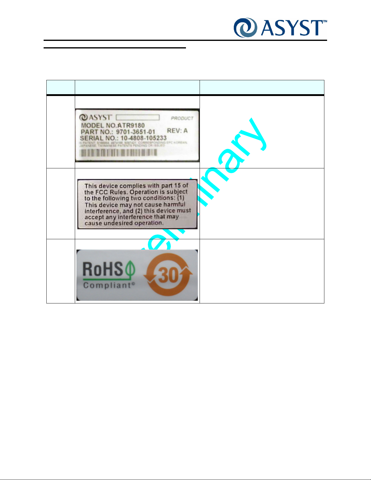
TABLE 2 Labels
No. Label Description/Location
1
2
3
Serial Number Label (9180 Reader) The model and serial number label for the
AdvanTag 9180 Reader is located on the bottom
of the unit. See Figure 2 on page 11.
These numbers are required when contacting
Asyst Technologies for any matter concerning
the equipment.
FCC Label The FCC label for the AdvanTag 9180 Reader is
located on the bottom of the unit. See Figure 2
on page 11.
RoHS The presence of this label indicates compliance
with regulations regarding Restriction of
Hazardous Substances (RoHS). The label is
located on the bottom of the unit. See Figure 2
on page 11.
Page 10 2000-6631-05 Draft Rev. Bx1
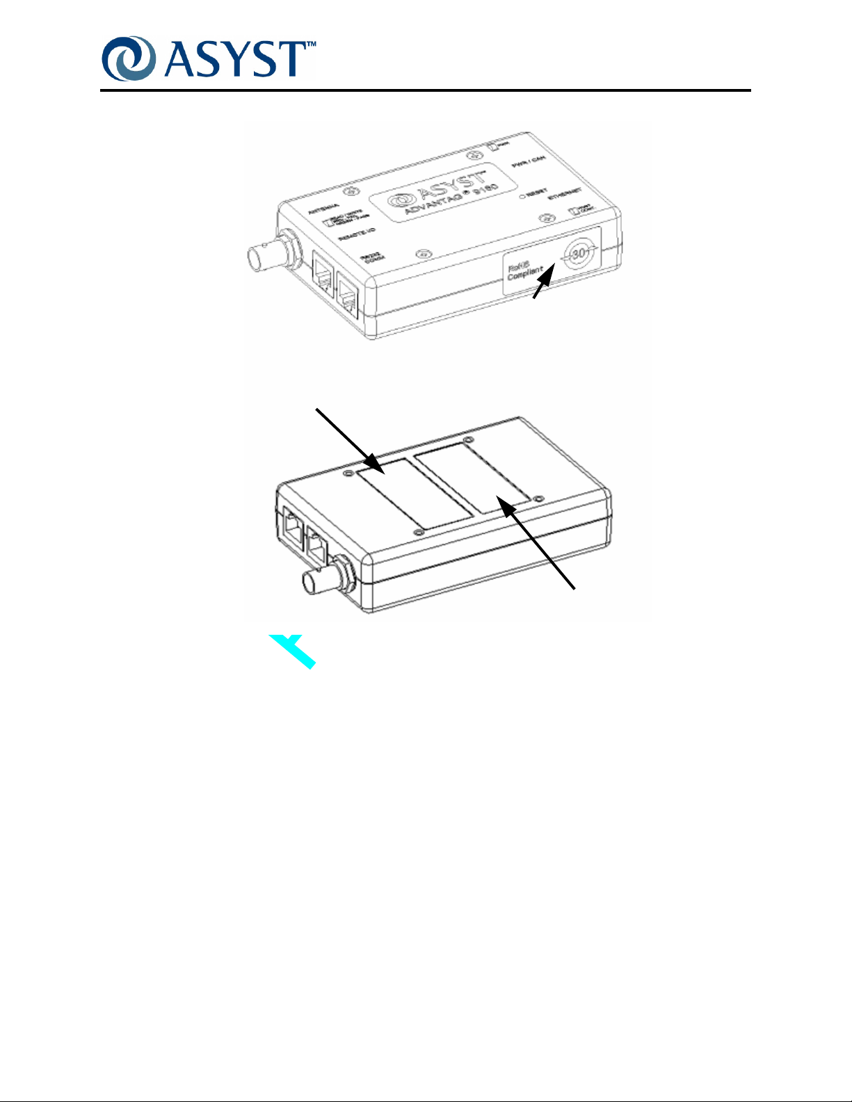
Location of Labels used on the AdvanTag
p
o
T
Serial Number Label
AdvanTag 9180 Technical Manual
Chapter 1: General Information
Labeling
RoHS Label
m
o
t
t
o
B
FCC Label
FIGURE 2 Label Locations, AdvanTag 9180 Reader
Draft Rev. Bx1 2000-6631-05 Page 11

AdvanTag 9180 Technical Manual
Chapter 1: General Information
Labeling
Page 12 2000-6631-05 Draft Rev. Bx1

Chapter 2: Theory of Operation
Product Description
The AdvanTag 9180 is a single Antenna Reader that reads and writes to the MicroTag
embedded in wafer cassettes, pods, FOUPs, reticle boxes, probe cards, photoresist
bottles, etc. The AdvanTag 9180 automatically communicates detailed lot information to a
process tool and fab CIM system when the lot arrives at a load port or during transport in
the AMHS.
LEDs
Antenna
Remote
I/O Port
E-Net
RS232 COMM
Power/CAN
F
IGURE 3 AdvanTag 9180 Top Views
Draft Rev. Bx1 2000-6631-05 Page 11

AdvanTag 9180 Technical Manual
Chapter 2: Theory of Operation
Product Description
The main component of this unit is a transmitter that generates radio waves through an
antenna. This TIRIS1 compatible, low-frequency (134.2 kHz), low-power RF energy is
used to read from or write to a transponder near the antenna. The 134.2 kHz carrier from
the RFID-ASIC is amplified to the proper levels to drive the dual MOSFET power
amplifier. This provides a 12V p-p low impedance drive to the antenna circuit. The
antenna is a series resonant LC circuit resonated at 134.2 kHz to achieve maximum
voltage on the antenna. The RFID Reader/Writer provides serial communication with a
host through an RS-232 port, using SECS protocol. It also supports HSMS protocol on its
LAN Port. Power is supplied by an external source. The Operating program is field
upgradeable using PICkit 2.
The AdvanTag 9180 is designed for versatile installation in many different situations. It
can be installed within OEM tools, within load ports, inside stockers, on WIP racks, in
storage cabinets, etc. Once a power source, an external antenna, and a communication
cable have been connected and the reader's address (TargetID and DeviceID as
described in “ Communications” on page 31) has been set, it is possible to communicate
using Stream 18 SECS messages or ASCII messages (depending on the host protocol
being used).
The software and hardware provide integrated self-test and diagnostics. A watchdog
timer and non-volatile memory provide power-failure recovery.
The AdvanTag 9180 operates on 24V DC (±10%) supplied by an external power source.
Communication is through a RS232 port, CAN Bus port (only for communicating with an
AdvanTag Gateway), or the Ethernet port.
TargetID
TargetID of the ATR9180 is configurable through the S18F3 command; default value = 1,
range = 1–99. The Remote I/O and the Antenna have the same ID.
Page 12 2000-6631-05 Draft Rev. Bx1

Using HSMS Protocol as Host
The HSMS supported by the ATR 9180 is derived from the SEMI E 37.1-96 single session
HSMS Standard.
The HSMS protocol can only be used in PASSIVE mode. The ATR 9180 would be used
as a PASSIVE device. In this mode of operation, the ATR 9180 opens up a socket that
listens for an incoming connection request from an ACTIVE HSMS host. After the initial
handshake, a connection between the Host and the ATR 9180 is established. Once a
connection had been established, the host and ATR 9180 can exchange messages
between each other.
To establish a connection with an ATR 9180, the following specific information must be
present with the host:
• ATR 9180 IP Address: The IP address of the ATR 9180 must be known to the host
so that a connection request could be made on that address. Please note that
HSMS is an IP address associated protocol thus for HSMS communication IP
address of the Passive entity must be known to the Active entity.
AdvanTag 9180 Technical Manual
Chapter 2: Theory of Operation
Using HSMS Protocol as Host
• ATR 9180 Port Number: The ATR 9180 opens a listening socket as mentioned
earlier but the connection is opened on an ETHERNET PORT. This number also
must be used by the Active entity (the host) to establish a connection.
NOTE . . .
IT MIGHT BE NOTED THAT THE IP ADDRESS ASSIGNED TO THE ATR 9180
WOULD BE A STATIC IP ADDRESS AND NOT ONE OBTAINED VIA DHCP SERVER.
THE REASON FOR THIS IS THAT HSMS IS AN IP ADDRESS BASED PROTOCOL.
Message Format and Translation
The messages as described in Section 1.1 have to be of the CIDRW SECS and ASCII
standard. The host could communicate with the ATR 9180 on either the RS-232 port or
the ethernet port. On the RS-232 port, the host could communicate over SECS or ASCII
version. When the host communicates over the ethernet, the communication would
happen over the HSMS protocol.
Each CIDRW SECS message (either on the SECS or HSMS port) would have a target ID
in its message body as an item. For example, the command Read MID (S18F9) has the
format
S18F9: 'S18F9' W
<A '##'>. * Target ID.
The item ## represents the Target ID of the node which the host wants to access.
Assuming the host needs to read the MID from node '01', following is the sequence of
operations that would take place:
Draft Rev. Bx1 2000-6631-05 Page 13

AdvanTag 9180 Technical Manual
Chapter 2: Theory of Operation
Using HSMS Protocol as Host
1. Host sends S18F9 command to the ATR 9180.
2. ATR 9180 parses the message for validity of data and format, extracts the Target ID
out of the data stream and then routes it to the correct antenna port.
S18F10
<L[4]
<A '01'> *Target ID
<A 'NO'> *SSACK
<A 'ABCDE'> *MID (Assuming ABCDE was the MID in MicroTag)
<L[4]
< A 'NE' >
< A 'O' >
< A 'IDLE' >
< A 'IDLE' >
>
>.
Messages Supported
The ATR 9180 supports only CIDRW ASCII and CIDRW SECS messages as described in
the message set documents P/N 2000-1455-01 and 2000-1442-01.
For any other message, the ATR sends back an error message saying that the command
is not supported.
Only one message at a time can be sent to the antennas. The host has to receive the
reply of a previous message before sending another message to the same node.
Specifications
• Firmware of the ATR9180 can be upgraded using PICkit 2.
• Can connect to a host on serial port at baud rates of 9600 and 19200.
• Supports a 10 Base-T ethernet connection for HSMS communication.
Page 14 2000-6631-05 Draft Rev. Bx1

Integration of Parts
Mounting
CAUTION
GENERAL HAZARD
ALL MOUNTING OPERATIONS SHOULD BE PERFORMED WITH
THE POWER CORD TO THE ADVANTAG DISCONNECTED. ALSO,
BE SURE THE 24 VDC POWER CONNECTOR IS
DISCONNECTED. FAILURE TO DISCONNECT BOTH COULD
RESULT IN DAMAGE TO THE ADVANTAG AND PERSONAL
INJURY FROM MECHANICAL AND/OR ELECTRICAL HAZARDS
WITHIN THE FRONT-LOAD ENCLOSURE.
I
F REMOVAL OF THE LOAD PORT FROM THE HOST TOOL IS
REQUIRED, ENSURE THAT THE POWER TO THE HOST TOOL IS
REMOVED AND THE POWER DISCONNECT DEVICE IS LOCKED
OUT IN THE OFF POSITION.
AdvanTag 9180 Technical Manual
Chapter 2: Theory of Operation
Integration of Parts
On the back of the AdvanTag reader, there are four M3 X .5 inserts that can be used for
mounting.
Other details:
• Install the AdvanTag reader in a dry and clean environment.
• The AdvanTag reader should be mounted to a grounded panel.
• The AdvanTag reader should be located as close as possible to the physical center of the devices that will be connected to it (the maximum recommended serial
cable length is 10 meters).
For more details, consult instructions for the appropriate installation kit.
Ports
For details on the AdvanTag reader’s ports, see “ Connectors” on page 27.
Draft Rev. Bx1 2000-6631-05 Page 15

AdvanTag 9180 Technical Manual
Chapter 2: Theory of Operation
Data Storage—AdvanTag Reader
Data Storage—AdvanTag Reader
Memory
The 9180 can read/write up to 136 bytes of data from/to the transponder (MicroTag). This
memory is divided into two sections. The first is for Material Identification (MID), which is
configurable using the attribute set and can be up to 136 bytes long (range: 8-136,
standard: 16). The second (Notepad) is for the balance of the memory. The amount of
available MID and Notepad memory is dependent upon the MicroTag used. Two types of
MicroTags are available, single page and seventeen page versions. Each page contains
64 bits, resulting in eight bytes of memory per page. MicroTags are available as read/write
or read only.
MicroTags
The AdvanTag reader can interact with MicroTags with regard to the following information:
SECS communication:
• Are You There - This message is used to perform the heartbeat between the host
and the connected device.
• Read Attribute Request - This message requests the current values of ECID or
SVID of the subsystem component indicated in TargetID.
• Write Attribute Request - This message requests the subsystem to set the value
of ECID of the component specified in TargetID to configure desired behavior.
Only applicable write-able attributes (like ECID) may be used in this message.
• Read Data Request - This message reads the “NOTEPAD” (Linear Memory) section of the subsystem component indicated in TargetID.
• Write Data Request - This message writes data to the NOTEPAD section of the
subsystem component indicted in TargetID.
• Read Material ID Request - This message is used to request the subsystem indicated by TargetID to read an MID.
• Write Material ID Request - This message is used to request the subsystem indicated by TargetID to write a Material identifier.
• Subsystem Command Request - This message is used to request the subsystem
indicated in TargetID to perform a specific action. Included in this set are the following commands: SSCMD 04 - LED BLINK/ON/OFF on Node Device; SSCMD
07 - Perform Diagnostics; SSCMD 13 - Reset; SSCMD 15 - Change State;
SSCMD GetStatus.
• Event Report Send - This message is used to send events to the host. Included in
this set are the following commands: CEID 01 - Material (Pod/Cassette) Arrival
Event; CEID 02 Material (pod/Cassette) Removal Event; CEID 08 - AdvanTag/LinkManager Power up.
• Read STATE Request - This message will query the CIDRW state of the transition
model.
Page 16 2000-6631-05 Draft Rev. Bx1

AdvanTag 9180 Technical Manual
Chapter 2: Theory of Operation
Data Storage—AdvanTag Reader
Retry Count Feature
The attribute RETRY_DIAGNOSTICS is a feature new to the AdvanTag family of readers.
This read-only attribute supports a diagnostic capability which allows the reader to
provide the number of retries performed in the last radio read/write command. Please
note that the information returned is the count for the previous read only.
Dual-Sensor Functionality
Dual-Sensor Host communicates with ATR9180 over serial port on SECS protocol.
New attributes added:
1. HOST_CONT_PORT1_LED (Value = ON/OFF)
Default value OFF. Set above attribute to ON using S18F3 commands Dual-Sensor
Functionality, HOST can control LED through S18F13 commands.
2. DUAL_SENSOR (Value = ON/OFF)
Default value OFF. Set above attribute to ON using S18F3 commands Dual-Sensor
Functionality.
Button 1 will produce Arrival Event (S18F71) with MID of the PILL. LED 1 stays ON during
read.
Button 2 will produce Removal Event (S18F75) with MID of the PILL. LED 2 stays ON
during read.
3. During Radio Operation on the Antenna port both LEDs on the port turn ON.
4. LED 1 corresponds to Button 1 and LED 2 corresponds to Button 2.
Led 1 and 2 can be addressable using Sub system command (S18F13) and can be
turned ON, OFF or BLINK.
Case 1. Button 1 press produces POD Arrival Event with S18F71 Message. LED 1 turns
ON till ATR reads the TAG and then turns OFF. LED ON Time should not be less than 1
Sec.
Case 2. Button 1 release doesn’t produce any event.
Case 3. Button 2 press produces POD Removal Event with S18F75 Message. LED 2
turns ON till ATR reads the TAG and then turns OFF. LED ON Time should not be less
than 1 Sec.
Case 4. Button 2 release doesn’t produce any event.
Case 5. LEDs are ON due to previous command (S18F13) and Radio is not busy in
Read/Write operation.
New command from the Host is executed right away.
Draft Rev. Bx1 2000-6631-05 Page 17

AdvanTag 9180 Technical Manual
Chapter 2: Theory of Operation
Data Storage—AdvanTag Reader
Case 6. LEDs are ON and Radio is BUSY in Read/Write operation.
New command from the Host is queued.
Case 7. LEDs are ON and Radio is busy in Read/Write operation button press should be
ignored.
Case 8. While Host is accessing the TAG LED 1,2 should turn ON and OFF once the
access is finished.
LED ON Time should not be less than 1 Sec.
Message Structure for S18F71 and S18F75 on Button Press is described below.
S18F71<L,4
<TargetID>
<SSACK> * SSACK STATUS -->NO/CE
<01> * CEID POD ARRIVAL Event
>
S18F75<L,4
<L,2
<”AUTOREADDATA”>
<MID>
>
<TargetID>
<SSACK> * SSACK STATUS -->NO/CE
<02> * CEID POD REMOVAL Event
<L,2
<”AUTOREADDATA”>
<MID>
>
>
Page 18 2000-6631-05 Draft Rev. Bx1

AdvanTag 9180 Technical Manual
Chapter 2: Theory of Operation
Data Storage—AdvanTag Reader
ABLE 3 ATR9180 Configuration for Dual-Sensor Operation
T
ATTRIBUTE VALUE
SECS_T1 5
SECS_T2 8
MANTWRITEONLY DI
CID_ERROR OFF
CID_PAD NUL
HOST_CONT_PORT1_LED ON
DUAL_SENSOR ON
HSMS Functionality
Single session HSMS protocol derived from the SEMI E37.1-96 standard over TCP/IP.
The unit only communicates over 10Mbps Ethernet speed. The HSMS support is based
on static IP address mechanism. The unit defaults to the following settings on HSMS.
LOCAL_IP_ADDRESS: 128.5.10.93
LOCAL_PORT: 5000
DEFAULT_GATEWAY: 0.0.0.0
SUBNET_MASK: 255.255.0.0
Only the settings shown above are required for establishing and maintaining the HSMS
connection on the ATR 9180.
The ATR 9180 support only the PASSIVE mode of HSMS communication. The host or the
remote entity should be always in the ACTIVE mode of HSMS in order to communicate
with the ATR 9180.
The HSMS functionality of the ATR 9180 is always enabled on the reader. The same unit
can work on HSMS without the need of downloading a different software.
NOTE . . .
THE ATR 9180 ALWAYS DEFAULTS TO THE SECS1 PROTOCOL OVER RS-232
WHEN SHIPPED FROM THE FACTORY.
Power Up Sequence of HSMS
When moving on to communicating over HSMS, the user needs to send the S18F3 (Write
Attribute Request) command on the RS-232 port over SECS1 protocol to set the LAN
settings to the required values and power cycle the unit.
The first time when the protocol is switched from SECS1 to HSMS, the power up event
S18F71 – CEID 8 will not be sent to the host. After this point, the software switches to the
Draft Rev. Bx1 2000-6631-05 Page 19

AdvanTag 9180 Technical Manual
Chapter 2: Theory of Operation
Data Storage—AdvanTag Reader
HSMS mode and every subsequent power cycle will result into a power up event sent to
the host after HSMS is connected.
To establish the connection, the host must send a Select.Req message to the ATR 9180
and in response to that, the ATR 9180 will send back a Select.Rsp message to declare
acceptance and HSMS CONNECTION establishment. Any of the CIDRW commands can
be sent after this stage.
HSMS Connection Management
Once the remote entity has dropped the connection, the ATR 9180 detects the break right
away to open up a new socket and get ready to accept a new connection from the remote
entity. The ATR 9180 generates its own Link Test request. It still replies back to the
LinkTest.Req message sent by the remote entity with a LinkTest.Rsp message. All the
CIDRW commands are supported as in the case of the RS-232 mode.
After being IDLE for LinkTest Frequency defined time the ATR 9180 sends a LinkTest.Req
message and starts a T6 timer to wait for LinkTest.Rsp from the remote entity. If the
response is not received during this timeout, the ATR9180 closes the previous socket and
opens a new one. The Host must reconnect on the same port.A similar socket disconnect
will take place when the LAN cable is removed from the ATR or the hub to which the ATR
is connected.
Event-Change Functionality
Event-Change Host communicates with ATR9180 over LAN port on HSMS protocol.
Event-Change functionality supports single sensor per port.
New attributes added:
1. HP_EVENT (Value = ON/OFF). Default value OFF. Set above attributes to ON using
S18F3 commands for HP functionality.
2. On Power up once HSMS is connected to the Host, all the Antenna ports are read and
respective MIDs are stored in the memory.
3. POD Arrival Event read respective Antenna port and MID read is stored in memory
and Event displays MID.
4. POD Removal Event returns MID read from last Arrival Event.
T
ABLE 4 ATR9180 Configuration for Event-Change operation
ATTRIBUTE VAL UE
HOST_CONT_PORT1_LED OFF
DUAL_SENSOR OFF
S18F71<L,4
<TargetID>
<SSACK> * SSACK STATUS -->NO/CE
Page 20 2000-6631-05 Draft Rev. Bx1

>
S18F71<L,4
AdvanTag 9180 Technical Manual
Chapter 2: Theory of Operation
Data Storage—AdvanTag Reader
<01> * CEID POD ARRIVAL Event
<L,2
<”AUTOREADDATA”>
<MID>
>
<TargetID>
<SSACK> * SSACK STATUS -->NO/CE
<02> * CEID POD REMOVAL Event
<L,2
<”AUTOREADDATA”>
<MID>
>
>
Default Values of R/W ATTRIBUTES
TABLE 5 Attribute Values (ECID and SVID)
Attribute Typ e Description and Limits or Values
AlarmStatus RO The Alarm Status
Value = 0 or 1
ASCII_T1 (ASCII only) RW Inter-byte timeout
Default = 100
BAUDRATE RW SECS and ASCII Baud rate 9600, 19200,
28800, and 57600 Default = 9600
CarrierIDOffset RW 0 to CID_MAX_LENGTH-1
CarrierIDOffset + CarrierIDLength <=
CID_MAX_LENGTH
Default = 0
CarrierIDLength RW 1 to CID_MAX_LENGTH
CarrierIDOffset + CarrierIDLength <=
CID_MAX_LENGTH
CID_MAX_LENGTH RW (8*N) N = Page1 to 17 Default = 16
CID_DISPLAY RW ON = Enable
OFF= Disable
Draft Rev. Bx1 2000-6631-05 Page 21
Default = ON
Default = 16

AdvanTag 9180 Technical Manual
Chapter 2: Theory of Operation
Data Storage—AdvanTag Reader
TABLE 5 Attribute Values (ECID and SVID)
Attribute Typ e Description and Limits or Values
CID_NP_ASCII RW ON = Enable
CID_ERROR RW ON = Enable
CID_JUSTIFY RW R = Right
CID_PAD RW NUL = 0x00
CID_E99_PAD RW ON = Enable
CHECKSUM (ASCII only) RW Checksum enabled or disabled.
OFF= Disable
OFF= Disable
L= Left
Default = L
ZERO = 0x30
OFF= Disable
EN = Enabled
DI = Disabled
Default = OFF
Default = ON
Default = ZERO
Default = OFF
Configuration RO 01 through 31
DEFAULT_GATEWAY
(HSMS only)
DEVICEID
(SECS only)
RW Default Gateway address for ATR9180.
Default: 0.0.0.0
RW DeviceID of the Target, used in the SECS1
Header
DUAL_SENSOR RW Dual Sensor operation enable/disable
Default = OFF
ENABLE_TIMEOUTS
(ASCII only)
RW Enable Communication Timeouts
ON = Timeout events will be generated.
OFF = Timeout events will not be generated.
Default = ON
ENABLE_EVENTS RW Enable Events (Pod or Operator
arrival/removal, and powerup.
ON = Event will be generated.
OFF = Events will not be generated.
Default = ON
EXTENDEDSSACK RW Enables the extended error codes in SSACK.
The SEMI standard specifies only five codes
(NO, EE, CE, HE, and TE). When this option
is ON, up to 100 error codes might be
generated.
Please see SSACK for all error code.
ON = All error codes generated.
OFF= Only SEMI standard error codes
generated
HeadID RO Returns the HeadID or TargetID
Two digits
Page 22 2000-6631-05 Draft Rev. Bx1

AdvanTag 9180 Technical Manual
Chapter 2: Theory of Operation
Data Storage—AdvanTag Reader
TABLE 5 Attribute Values (ECID and SVID)
Attribute Typ e Description and Limits or Values
HeadStatus RO IDLE or MANT
HOST_CONT_PORT1_LED RW LED controlled by Host on Remote I/O Port 1
Default = OFF
HSMS_T5
(HSMS only)
HSMS_T6
(HSMS only)
HSMS_T7
(HSMS only)
HSMS_T8
(HSMS only)
LOCAL_IP_ADDRESS
(HSMS only)
LOCAL_PORT
(HSMS only)
LinkTestFrequency
(HSMS only)
RW T5 Timeout in HSMS
(1 - 240 sec.)
Default = 10
RW T6 Timeout in HSMS
(1 - 240 sec.)
Default = 10
RW T7 Timeout in HSMS
(1 - 240 sec.)
Default = 10
RW T8 Timeout in HSMS
(1-120 sec.)
Default = 10
RW Local IP Address.
Default: 128.5.10.93
RW Local port on which the ATR 9180 would
listen Default: 5000
RW This timer is used to send periodic link test
messages. If a response is not received the
connection is dropped.
Default: 20 seconds
Manufacturer
(Applicable only to version 21A
and later)
MANTWRITEONLY RW If this attribute is enabled, then MID (CID)
MDLN RO Asyst Model designation of Upstream
ModelNumber
(Applicable only to version 21A
and later)
OperationalStatus RW IDLE or MANT
Draft Rev. Bx1 2000-6631-05 Page 23
RO Returns “Asyst”
and Data is read and written according to the
E99 standard
EN = Enable
DI = Disable
Default = EN
Controller OR Head (as applicable)
Up to 6 bytes
RO Same as MDLN
Note: Set through only Subsystem commands

AdvanTag 9180 Technical Manual
Chapter 2: Theory of Operation
Data Storage—AdvanTag Reader
TABLE 5 Attribute Values (ECID and SVID)
Attribute Typ e Description and Limits or Values
PIP_AUTOREAD RW Auto read On or OFF
PIP_AUTOREAD_DATA RW The memory type to read upon Pod-In-Place
PIP_AUTOREAD_LENGTH RW Length of NOTEPAD data to read upon Pod
ON = On
OFF = Off
Default = ON
Event:
(Offset, or MID)
Note: Offset applies only to NOTEPAD.
Note: This attribute should be modified with
respect to PIP_AUTOREAD_LENGTH
Default = MID
arrival.
Note: Applicable only if data type is
NOTEPAD
Note: This attribute should be modified with
respect to PIP_AUTOREAD_DATA
Default = 16
PIP_SENSOR_POLARITY RW PIP Sensor Polarity.
HI = Active-High. When Sensor goes high,
Pod Arrival event is generated
LO = Active-Low. When Sensor goes low, Pod
Arrival event is generated
Default = LO
RETRY_DIAGNOSTICS R Returns number of retries that occurred during
last radio read/write operation.
RADIO_RETRY RW Retry Count for Radio operation in case of
failure
Default: 3
RDA RW AdvanTag returns either RD or RDA in
response to the ASCII RD command.
EN = Enabled, returns RDA
DI = Disabled, returns RD
Default = EN
SENSOR_TIMEOUT RW Value 1 - 20
Default 10
SCAN_ENABLE RW Value = ON/OFF
Default = OFF
SECS_T1 (SECS only) RW SECS T1 timeout
Default = 5
SECS_T2 (SECS only)
(Host port on LM)
Page 24 2000-6631-05 Draft Rev. Bx1
RW SECS T2 timeout
Default = 50

AdvanTag 9180 Technical Manual
Chapter 2: Theory of Operation
Data Storage—AdvanTag Reader
TABLE 5 Attribute Values (ECID and SVID)
Attribute Typ e Description and Limits or Values
SECS_T3 (SECS only)
(Host port on LM)
SECS_T4 (SECS only)
(Host port on LM)
SECS_RETRY (SECS only)
(Host port on LM)
SOFTREV RO Subsystem Software Rev. of Upstream
SoftwareRevisionLevel RO Same as SOFTREV
SELF_TEST_RESULT RO Last self test result
STATUS_ENABLE RW If set to Enable communicates Status
SUBNET_MASK (HSMS only) RW Default Subnet Mask for ATR 9180. Default:
TARGETID RW The TargetID of the device
RW SECS T3 timeout
Default = 45
RW SECS T4 timeout
Default = 45
RW SECS-1 Protocol Retry limit
Default = 3
Controller OR Head (as applicable)
6 bytes
P = Pass
F = Fail
information of the Head. Default “EN”.
255.255.0.0
Please refer to the Asyst CIDRW Messages SECS protocol manual (Asyst part number
2000-1442-01) and Asyst CIDRW Messages ASCII protocol manual (Asyst part number
2000-1455-01) for more detailed information on communication with the AdvanTag.
Draft Rev. Bx1 2000-6631-05 Page 25

AdvanTag 9180 Technical Manual
Chapter 2: Theory of Operation
Interfaces
Interfaces
There are three LEDs to signify activity, a RESET button, and a switch panel for
specifying the unit's address (TargetID). See below for more details.
LEDs
The LEDs located on the top of the reader (see Figure 4) indicate the operational status
of the AdvanTag.
Read/Write LED
Power LED
Host Controller LED
F
IGURE 4 AdvanTag 9180 Reader LEDs
Power Indicator LED
The POWER indicator, when lit, indicates that power is applied to the AdvanTag.
Light Status Power
Off No power
Green Power on
Host Controller LED
Green, controllable by host command (on/off/blinking).
Page 26 2000-6631-05 Draft Rev. Bx1

AdvanTag 9180 Technical Manual
Chapter 2: Theory of Operation
Read/Write LED
The Read/Write LED indicates communication status:
Light Communication Status
Off Radio off
Green Successful read/write
Red Read/Write failure (details below)
Read/Write failures occur as a result of one of the following:
• Attempted to read multiple pages of a single-page MicroTag
• Multiple MicroTags are in range
• No MicroTags are in range
• Attempted a write operation on a read-only MicroTag or a looked page
Interfaces
For read/write ranges, see “ Antenna Performance” on page 38.
Connectors
The AdvanTag reader features four external ports.
Power
The port labeled PWR is for a power supply of 24VDC. Asyst can supply a 120-220V
adapter (Asyst P/N 6200-6210-01) or the OEM can supply this power.
This is a DB9 male receptacle, 24 VDC (+/- 10%), 70mA typical, 350mA maximum. See
Table 1, “AdvanTag 9180 Specifications,” on page 5 for further details. The following table
shows the pin outs.
T
ABLE 6 Power Cable Pin Outs
Pin Signal
1Not Used
2 CAN Low
3 Signal Ground
4Not Used
5 Power Ground
6 Signal Ground
7 CAN High
8Not Used
9+24VDC
Draft Rev. Bx1 2000-6631-05 Page 27

AdvanTag 9180 Technical Manual
Chapter 2: Theory of Operation
Interfaces
Communication
The port labeled RS232 COMM is for RS232 communication.
This is a shielded RJ45 socket. A cable which connects the Reader to a PC is available
from Asyst.
ABLE 7 Serial Port Pin Usage
T
Pin
Number
1 (N/C) not used
2 (N/C) not used
3 (N/C) not used
4 Ground X
5 TX X
6 RX X
7 (N/C) not used
8 (N/C) not used
Name
Serial Comm
(SECS/ASCII) RJ45
CAUTION
ELECTRICAL HAZARD
DO NOT TOUCH THE INSIDE OF THE ANTENNA CONNECTOR.
FAILURE TO COMPLY MAY RESULT IN INJURY.
Antenna
CAUTION
ANTENNAS SHOULD ONLY BE INSTALLED BY QUALIFIED
PERSONNEL. FAILURE TO COMPLY MAY RESULT IN
MALFUNCTION OR DAMAGE TO THE UNIT AND/OR ANTENNA.
The port labeled REMOTE ANTENNA is for an external antenna. Contact Asyst for
available antennas.
This is a BNC socket; use with Asyst antennas is required.
Page 28 2000-6631-05 Draft Rev. Bx1

AdvanTag 9180 Technical Manual
Chapter 2: Theory of Operation
Interfaces
CAUTION
GENERAL HAZARD
NEVER USE A NON-ASYST ANTENNA WITH THE ADVANTAG
9180. F
CERTIFICATION.
AILURE TO COMPLY WILL VOID FCC AND CE
External Presence
The port labeled REMOTE I/O is for an external presence sensor that detects events
such as pod arrival and pod removal.
The REMOTE I/O port is a shielded RJ45 socket used for the external presence sensor.
Pin Signal Input/Output
+5 or +12 VDC Output
1
Sensor 1 Input
2
3
4
5
6
7
8
NOTE . . .
POWER OUTPUT IS CONFIGURABLE AND SELECTED BY USE OF JUMPERS
APPLIED TO THE PRESENCE SENSOR. JUMPER PINS 1&2 FOR +12VDC AND
JUMPER PINS 2&3 FOR +5VDC.
LED 1 Output
Ground
LED 2 Output
NC
Sensor 2 Input
NC
Draft Rev. Bx1 2000-6631-05 Page 29

AdvanTag 9180 Technical Manual
Chapter 2: Theory of Operation
Interfaces
Ethernet
The Ethernet port is a shielded RJ45 socket used for communication to a host using
HSMS.
Use a standard CAT5 Ethernet straight cable when connecting the ATR9180 to a 10/100
Mbps hub or switch. A shielded ethernet cable is preferred.
NOTE . . .
FOR INFORMATION ON COMMUNICATION THROUGH ALL PORTS, PLEASE REFER
TO THE SOFTWARE MANUAL.
Buttons/Switches
Reset
Press this button (see Figure 5) to reset the unit. The default baud rate is 9600.
NOTE . . .
THE ATR9180 WILL TAKE 10 SECONDS TO BOOT UP AND RUN THE SOFTWARE.
IGURE 5 Locating the Reset Switch
F
Code Upgrade
Code Upgrade of the ATR9180 can be performed using PICkit 2. The Procedure can be
found in the ATR9180 Upgrade Procedure P/N 2000-6779-01.
Reset
Switch
Page 30 2000-6631-05 Draft Rev. Bx1

Communications
To Host
The AdvanTag reader communicates to the host via RS-232 or LAN ports.
NOTE . . .
THE ATR9180 REMEMBERS THE LAST PROTOCOL USED TO COMMUNICATE. THE
DEFAULT PROTOCOL IS SECS WITH 4 RETRIES.
Read Range
Typical read range of the AdvanTag reader is 10-12 cm. Read range is dependent on the
antenna design and the operational environment in which the antenna is installed. See “
Antenna Performance” on page 38 for further details.
AdvanTag 9180 Technical Manual
Chapter 2: Theory of Operation
Communications
SECS
Refer to the specific protocol documentation concerning Stream 18 SECS messages for
details. The basic functions available are to read and write attributes, read and write
material IDs (MIDs), read and write data, and various subsystem commands such as
turning an LED on or off. Note that the single-page transponders hold an 8 byte MID only
and the multi-page transponders hold a 16-byte MID and 120 bytes of data.
The TargetID (as described in the SEMI E99 and E5 standards) can be set with the
S18F3 command; default value is 1. The SECS I DeviceID can be set through an
attribute. The baud rate can also be set through an attribute setting. Byte format is 8 data
bits, 1 stop bit and no parity. The SECS I timeouts and retries can be set through attribute
settings; defaults are T1 = 0.5 secs, T2 = 10 secs, T3 = 45 secs, T4 = 45 secs, Retries =
3.
Serial Communications Interface
The AdvanTag has one port for serial-computer-communications interface (Asyst P/N
9701-2914-XX). It is an RJ45 RS232 interface. It has a transmit (TX) and a receive (RX)
line and ground. See Table 7 on page 28.
Ethernet Communications
The ATR 9180 has an Ethernet port, which is an RJ45 socket. Communication protocol is
single session HSMS.
Draft Rev. Bx1 2000-6631-05 Page 31

AdvanTag 9180 Technical Manual
Chapter 2: Theory of Operation
Software
Software
For more software information, please refer to the Asyst CIDRW Messages SECS
protocol Manual (Asyst part number 2000-1442-01) and the Asyst CIDRW Messages
ASCII protocol Manual (Asyst part number 2000-1455-01).
Page 32 2000-6631-05 Draft Rev. Bx1

Web Configurator
The ATR 9180 supports a web configurator on ethernet using HTTP Protocol. See Figure
6 for Web Interface Home Page.
AdvanTag 9180 Technical Manual
Chapter 2: Theory of Operation
Web Configurator
F
IGURE 6 ATR 9180 Web Interface - Home Page
HSMS Configuration
Upon clicking HSMS Configuration link on the main page, the configuration page is
displayed. The configuration page takes a few seconds to load as it reads all the
necessary configuration attributes from the flash and displays the values against the
name in a tabular format as shown in Figure 7 on page 34.
Draft Rev. Bx1 2000-6631-05 Page 33

AdvanTag 9180 Technical Manual
Chapter 2: Theory of Operation
Web Configurator
WARNING:
FIGURE 7 Web Interface - Configuration Page
NOTE . . .
THE VALUES IN TEXT BOXES ARE THE DEFAULT VALUES FOR THE ATTRIBUTE.
T
HE ACTUAL (CURRENT) VALUE OF THE SAME ATTRIBUTE IS DISPLAYED IN THE
BRACKET NEXT TO THE TEXT BOX. EXAMPLE: IN FIG THE ATTRIBUTE
ARRIERIDOFFSET HAS THE CURRENT VALUE AS 0 AND THE DEFAULT VALUE IS
C
ALSO 0.
To change the value of any of the attributes, the new value must be entered in the text
box (which always shows the default value). Once the new value has been entered, click
on the Write ___ Attributes button to write the attributes to the flash memory.
Page 34 2000-6631-05 Draft Rev. Bx1

AdvanTag 9180 Technical Manual
Chapter 2: Theory of Operation
Web Configurator
Read-Write Radio
Upon clicking Read-Write Radio link on the main page, the Read Write page is displayed.
See Figure 8. The Read Write page is divided in two parts Read and Write. The read
commands are Read MID and Read Data. The write commands are Write MID and Write
Data
F
IGURE 8 Web Interface - Read Write Page
Read
Read MID is a simple HTML link which executes a ReadMID command on the reader and
returns the ID on the web page along with the Error/Success code. The Read MID
command would be executed by clicking the Read MID button on the read/write page.
See Figure 9 for sample response.
IGURE 9 Read MID Response
F
Draft Rev. Bx1 2000-6631-05 Page 35

AdvanTag 9180 Technical Manual
Chapter 2: Theory of Operation
Web Configurator
A Read Data command would be executed by entering Offset and Data length in the
fields provided and clicking the Read Data button on the read/write page. See Figure 10
for sample response.
NOTE . . .
OFFSET AND DATA LENGTH MUST BE ENTERED IN ORDER TO READ THE
NOTEPAD DATA FROM THE TAG.
The maximum data that could be read through the web read data interface is 45 bytes.
IGURE 10 Read Data Response
F
Write
The Write MID button writes the MID entered in the text box in front of the Write MID
button to the MID area of the tag. Enter the MID to be written in the text box in front of the
Write MID button then click on the Write MID button. Figure 11 displays a sample
response.
F
IGURE 11 Write MID Response
Page 36 2000-6631-05 Draft Rev. Bx1

The Write Data button writes the data entered in the data field of the page to the Notepad
area of the tag.Enter the Data to be written in the text box in front of the Write Data button
then click on the Write Data button. Figure 12 displays a sample response.
NOTE . . .
OFFSET AND DATA LENGTH MUST BE ENTERED IN ORDER TO WRITE THE
NOTEPAD DATA TO THE TAG.
AdvanTag 9180 Technical Manual
Chapter 2: Theory of Operation
Web Configurator
F
IGURE 12 Write Data Response
Draft Rev. Bx1 2000-6631-05 Page 37

AdvanTag 9180 Technical Manual
Chapter 2: Theory of Operation
Antenna Performance
Antenna Performance
The AdvanTag antennas work in conjunction with the AdvanTag Reader ATR9180 to read
and write the MicroTag. Communications occur between the antenna and the MicroTag
using very low radio frequency (134.2khz). Performance of these antennas (read and
write distance as well as speed) is affected by the presence of metal and RF generators,
such as color monitors in the antenna communication field.
Read/Write Performance Factors
Factors that influence tag read and write performance:
• Proximity of the tag and antenna
• Length of cable between the AdvanTag Reader and the antenna (including exten-
sion cables)
• Orientation of the tag to the antenna
• Amount of metal adjacent to either the tag or the antenna
• Amount of background EMF in the environment
NOTE . . .
IF AN ANTENNA IS POSITIONED AGAINST A MICROTAG, THE ANTENNA WILL NOT
READ IN MOST CASES. ALL OF THE RESULTS LISTED WERE TESTED IN AN OFFICE
ENVIRONMENT.
RF Field Diagrams
The diagrams accompanying the types of antenna for reference only. Note the following
conditions for each diagram:
• The coil of micro-tag must be completely contained in write area.
• The shaded area in center is a non-write area (null).
• Write ranges are approximately 50% of read ranges.
• The read and write distances cited are for reference only. Ranges are dependent
upon actual installed environment.
• It may not be possible to replicate the same results outside of lab environments
due to a variety of environmental conditions.
Page 38 2000-6631-05 Draft Rev. Bx1

AdvanTag 9180 Technical Manual
Chapter 2: Theory of Operation
Antenna Performance
Stick Antennas
The stick antenna 9701-2879-03 is designed to be attached to the external antenna
connector of the ATR 9180 and optimized for use in a variety of applications. The average
read range is 10-12 cm. This stick antenna diagram refers to a stick antenna as being flat
on the YZ axis, centered at 0,0,0.
Read Pattern using 9701-2879-03 antenna in air
Transponder in vertical position relative to antenna
(distance units in mm)
0º
10º
20º
30º
40º
50º
60º
70º
290º
300º
310º
320º
330º
340º
350º
140
120
100
80
60
40
280º
270º
260º
250º
240º
230º
20
0
220º
210º
200º
190º
F
IGURE 13 Vertical Read Range
180º
170º
80º
90º
100º
110º
120º
130º
140º
150º
160º
Draft Rev. Bx1 2000-6631-05 Page 39

AdvanTag 9180 Technical Manual
Chapter 2: Theory of Operation
Antenna Performance
Read Pattern using 9701-2879-03 antenna in air
Transponder in horizontal position relative to antenna
330º
320º
310º
(distance units in mm)
0º
340º
350º
160
140
120
100
10º
20º
30º
40º
50º
290º
280º
270º
260º
250º
300º
240º
230º
220º
210º
200º
190º
80
60
40
20
0
180º
170º
60º
70º
80º
90º
100º
110º
120º
130º
140º
150º
160º
FIGURE 14 Horizontal Read Range
Page 40 2000-6631-05 Draft Rev. Bx1

Chapter 3: Troubleshooting
This chapter identifies common problems that may occur when using the AdvanTag 9180
unit and provides a step-by-step process to identify the root cause for reader
failure/malfunction and common solutions.
It includes:
• “ Troubleshooting Chart” on page 41
• “ Troubleshooting for RS232” on page 42
• “ Troubleshooting for HSMS ATR9180” on page 43
• “ For Additional Troubleshooting Assistance” on page 45
Troubleshooting Chart
If there are any other problems, or if none of the corrective actions/solutions shown in this
chapter clears the problem, replace the AdvanTag 9180.
ABLE 8 ATR 9180 Common Errors and Solutions
T
Error or Symptom Likely Cause(s) Corrective Action
Unit not functioning
properly
During read and write
programs, the
READ/WRITE LED turns
red.
During read and write
programs, the
READ/WRITE LED turns
red instead of green.
During read and write
programs, the
READ/WRITE LED does
not blink.
No Power - LEDs on the
front of the unit are not
illuminated.
Communication cables loose
or disconnected.
MicroTag or antenna is not
installed correctly.
MicroTag is not present or
out of range.
The antenna cable is loose.
The antenna is bad.
The RS232 cable is loose.
The RS232 cable is bad.
The ATR is bad.
Host command is wrong.
Check connection for power cables. Make
sure the power is connected and then verify
the Power LED is lit.
Check the power supply being used. Swap
with another power supply to make sure that
the power supply is functioning properly.
Check serial cables for loose connector.
Check connector for bent pin(s).
Install MicroTag correctly. The
READ/WRITE LED should turn green only.
Refer to ATR magnetic field pattern diagram.
Install MicroTag or antenna properly. The
READ/WRITE LED should turn green.
Tighten the antenna cable.
Replace the antenna.
Adjust the location of the antenna.
Tighten the RS232 cable.
Replace the RS232 cable.
Replace the ATR.
Check Host command and target ID.
Draft Rev. Bx1 2000-6631-05 Page 41

AdvanTag 9180 Technical Manual
Chapter 3: Troubleshooting
Troubleshooting for RS232
Troubleshooting for RS232
Problem ATR9180 P/N 9701-3651-01 fails to follow normal power up sequence.
1. Turn the ATR9180 power on and observe the Host Controller LED.
It should turn ON for a second and then it should turn OFF. This verifies power-on
sequence and that the software is running.
If the ATR9180 does not follow this power on process then the unit may be defective
or the software is not functioning.
Solution
Upgrade the software using PICkit 2 (refer to upgrade procedure document, PN
2000-6779-01), restart the ATR9180, and observe the power-on sequence.
A successful power-on sequence at this time means that there was no software in the
unit. A failed power-on sequence at this time means that the hardware in the unit may
have been damaged.
• For further information, refer to the SW Release Notes (PN 2000-6719-01).
Problem No RS232 Communication
Solution
Check for loose connectors and cables.
Use only the cable recommended by Asyst Technologies, Inc. Asyst part number
9700-4859-XX (non-ROHS)/ 9701-2914-XX (RoHS).
NOTE . . .
THE ATR9180 MUST BE RESTARTED AFTER CHANGING TARGET ID USING A
WRITE ATTRIBUTE S18F3 COMMAND.
Page 42 2000-6631-05 Draft Rev. Bx1

Problem No Communications After a Hard Reset
Solution
A brand new ATR9180 on hard reset (see Asyst document 2000-1442-01 for details)
communicates power up event to the Host in SECS protocol. If the host is not present
ATR9180 will go in to retry mode and retry 3 more times before finally timing out. Timeout
is approximately 45 seconds. If you are using ASCII protocol, wait until SECS has
finished retrying. Then send the ASCII message.
NOTE . . .
THE ATR9180 REMEMBERS THE PREVIOUS SUCCESSFUL PROTOCOL IT
COMMUNICATED ON AND WILL CONTINUE TO COMMUNICATE WITH THAT
MESSAGE SET.
AdvanTag 9180 Technical Manual
Chapter 3: Troubleshooting
Troubleshooting for HSMS ATR9180
Troubleshooting for HSMS ATR9180
Troubleshooting guide for the 9701-3651-01 ATR 9180
NOTE . . .
THIS ATR WORKS AT ONLY 10 MBPS SPEED.
Problem ATR 9180 does not respond to ping command
Solution
1. Check the IP address, subnet mask and default gateway settings of the ATR. The IP
address must be unique for every ATR. The subnet mask of the PC and that of the
ATR should be same. The default gateway entry should also be the same.
2. To ensure that the proper software is installed, observe the ethernet LED on the LAN
connector.
3. Try changing the IP address to some other value. If an ATR is used with one address
and another one is connected after disconnecting the first from the network, the new
ATR will not be able to use the same IP address. In this case the new ATR must be
set to a new address.
4. Try clearing the arpcache from the PC.
Refer to the Software Release Notes (2000-6719-01) on how to configure the IP address.
Draft Rev. Bx1 2000-6631-05 Page 43

AdvanTag 9180 Technical Manual
Chapter 3: Troubleshooting
Troubleshooting for HSMS ATR9180
Problem The LED on the hub does not turn ON
Solution
1. Check the LAN cable used. When connected to a hub, a straight CAT 5 cable must be
used to connect the ATR 9180.
2. The port on which the ATR is connected is bad. Move the ATR cable to some other
port on the hub, and try again.
Problem No Communication with Tag
Solution
1. Make sure a TIRIS tag is present and positioned in the correct orientation and position
relative to the antenna. See the antenna read/write range graphs for details on the
correction locations.
2. Verify the Antenna is connected properly to ATR9180.
3. Check the orientation of the antenna.
4. Make sure there are no metallic objects within 30mm of the antenna or the TIRIS Tag.
5. Check to ensure that only one TIRIS tag is within the read range of the antenna.
Multiple tags in the read range of the antenna will prohibit reading of any tag.
Page 44 2000-6631-05 Draft Rev. Bx1

AdvanTag 9180 Technical Manual
Chapter 3: Troubleshooting
For Additional Troubleshooting Assistance
For Additional Troubleshooting Assistance
If you continue to have problems working with the ATR 9180, please collect the following
information and contact Asyst Technical Support at 1-800-342-SMIF (7643), enter 2 then
3 or e-mail techsupport@asyst.com for assistance.
1. Part Number and Serial Number of ATR9180
2. Part Number of RS232 cable connected
3. Part Number of the power supply
4. Part Number of the Antenna
5. Software Revision Level
6. Note the type of Presence Sensor connected, if any
7. List of responses to troubleshooting steps listed in this chapter
To Determine Software Revision
While Observing the power up event on the Host side, send a S1F1 SECS command with
AConfig and note the software revision in the return message from the ATR9180.
If there are any other problems, or if none of the above corrective actions clears the
problem, replace the AdvanTag. Other considerations to assure proper ATR functioning:
• The baud rate is to be the same between Host and ATR.
• The target ID is to be correct in the SECS message that gets sent to the ATR.
• The MicroTag is to be in the proper range and relative location to the antenna.
Draft Rev. Bx1 2000-6631-05 Page 45

AdvanTag 9180 Technical Manual
Chapter 3: Troubleshooting
For Additional Troubleshooting Assistance
Page 46 2000-6631-05 Draft Rev. Bx1

Appendix A: Functional Test Log
5/4/2007 10:58:20 AM - RECEIVED PRIMARY MESSAGE: S18F71
<L
<A 01>
<A NO>
<A 8> <== Power Up Event
<L
>
>.
10:58:20 AM - PRIMARY MESSAGE SENT:
S1F1
.
10:58:20 AM - RECEIVED SECONDARY REPLY: S1F2
<L
< A AT9180 >
< A R10B > <== R U There
>
READ MID CMD
10:58:36 AM - PRIMARY MESSAGE SENT:
S18F9
< A 1 > <== Read MID
10:58:37 AM - RECEIVED SECONDARY REPLY: S18F10
<L
<A 01>
<A NO>
<A Antenna Port --8>
<L <== Read MID Response
<A NE>
<A 0>
<A IDLE>
<A IDLE>
>
>.
WRITE 120 Bytes
11:00:11 AM - PRIMARY MESSAGE SENT:
S18F7
<L
<A 1>
<A 00>
<A 120> <== Write 120 bytes Data
<A
Draft Rev. Bx1 2000-6631-05 Page 47

AdvanTag 9180 Technical Manual
Appendix A: Functional Test Log
test 120 bytes write using ATR9180.test 120 bytes write using ATR9180.test 120 bytes
write using ATR9180.end of the data
>.
11:00:16 AM - RECEIVED SECONDARY REPLY: S18F8
<L
<A 01>
<A NO> <== Write Data Request Success
<L
<A NE>
<A 0>
<A IDLE>
<A IDLE>
>
>.
READ 120 bytes
11:00:28 AM - PRIMARY MESSAGE SENT:
S18F5
<L
<A 1>
<A 00>
<A 120> <== Read 120 Bytes Data
>.
11:00:30 AM - RECEIVED SECONDARY REPLY: S18F6
<L
<A 01>
<A NO> <== Read 120 Bytes Data Success
<A
test 120 bytes write using ATR9180.test 120 bytes write using ATR9180.test 120 bytes
write using ATR9180.end of the data
>.
11:02:03 AM - PRIMARY MESSAGE SENT:
S18F13
<L
<A 1>
<A 15>
<A M> <== MANT Mode ON
>.
11:02:03 AM - RECEIVED SECONDARY REPLY: S18F14
<L
<A 01>
<A NO>
<L
Page 48 2000-6631-05 Draft Rev. Bx1

<A NE>
<A 0>
<A MANT>
<A IDLE>
>
>.
WMID:
11:02:42 AM - PRIMARY MESSAGE SENT:
S18F11
<L
<A 1>
<A ATR9180--PORT001><== Write MID CMD
>.
11:02:43 AM - RECEIVED SECONDARY REPLY: S18F12
<L
<A 01>
<A NO> <== Write MID Success
<L
<A NE>
<A 0>
<A MANT>
<A IDLE>
>
>.
AdvanTag 9180 Technical Manual
Appendix A: Functional Test Log
READ:
11:02:50 AM - PRIMARY MESSAGE SENT:
S18F9
< A 1 > <== Read MID
11:02:50 AM - RECEIVED SECONDARY REPLY: S18F10
<L
<A 01>
<A NO> <== Read MID Success
<A ATR9180--PORT001>
<L
<A NE>
<A 0>
<A MANT>
<A IDLE>
>
>.
Draft Rev. Bx1 2000-6631-05 Page 49

AdvanTag 9180 Technical Manual
Appendix A: Functional Test Log
SUB SYSTEM CMD - LED ON
11:04:06 AM - PRIMARY MESSAGE SENT:
S18F13
<L
<A 1>
<A 04> <== Sub System CMD Turn LED 1 of Port 1 ON
<L
<A 1>
<A 10>
<A 1>
>
>.
11:04:06 AM - RECEIVED SECONDARY REPLY: S18F14
<L
<A 01>
<A NO> <== Sub System CMD Success
<L
<A NE>
<A 0>
<A MANT>
<A IDLE>
>
>.
SET DUAL SENSOR ON FOR DUAL SENSOR FUNCTIONALITY
11:08:14 AM - PRIMARY MESSAGE SENT:
S18F3
<L
<A 1>
<L
<L
<A DUAL_SENSOR><== Turn Dual Sensor ON
<A ON>
>
>
>.
11:08:14 AM - RECEIVED SECONDARY REPLY: S18F4
<L
<A 01>
<A NO> <== Write attribute success
<L
<A NE>
<A 0>
<A MANT>
<A IDLE>
>
>.
Page 50 2000-6631-05 Draft Rev. Bx1

AdvanTag 9180 Technical Manual
Appendix A: Functional Test Log
ARRIVAL /REMOVAL EVENT
5/4/2007 11:08:22 AM - RECEIVED PRIMARY MESSAGE: S18F71
<L
<A 05>
<A NO> <== Port 5 Button 1 is pressed
<A 1>
<L
<A AutoReadData>
<A 1234567890123456><== MID read
>
>.
5/4/2007 11:08:26 AM - RECEIVED PRIMARY MESSAGE: S18F75
<L
<A 05>
<A NO> <== Port 5 Button 2 is pressed
<A 2>
<L
<A AutoReadData>
<A 1234567890123456><== MID read
>
>.
Cycle Testing
Cycle Testing Setup
Host : Secsim Pro 3.0.4
Communication Port : RS-232 , 9600 baud rate
Result : PASS
Draft Rev. Bx1 2000-6631-05 Page 51

AdvanTag 9180 Technical Manual
Appendix A: Functional Test Log
Page 52 2000-6631-05 Draft Rev. Bx1

Appendix B: HSMS Test Log
This Appendix consists of a sample test log of HSMS Communications.
Sample Log
Primary message : RUTHERE, Send to Dev ID : 1
(0) Sending Primary Message...
<S1F1 W>
(0) HSMS: Sending SECS Message to 128.5.10.93
(0) HSMS: Message = 00 01 81 01 00 00 00 05 16 9C
(0) HSMS: Received SECS Message from 128.5.10.93
(0) HSMS: Message = 00 01 01 02 00 00 00 05 16 9C 01 02 41 06 41 54 39 31 38 30
(0) HSMS: 41 06 41 31 30 41 62 38
(0) Received Reply Message...
<S1F2
<L[2/1]
<A[6/1] "AT9180">
<A[6/1] "A10Ab8"><-- This value will be A10A for the release.
>
>
Received Stream : 1, Expected Stream : 1
Received Function : 2, Expected Function : 2
Received Items : <L[2/1]
<A[6/1] "AT9180">
<A[6/1] "A10Ab8">
>
Status : S_DONE : Normal Completion of Primary sent, Received correct Reply,
W-Bit=1
-------------------------------------------------------------------Primary message : GETSWPART, Send to Dev ID : 1
(0) Sending Primary Message...
<S18F1 W
<L[2/1]
<A[2/1] "01">
<L[1/1]
<A[13/1] "SW_PARTNUMBER">
>
>
>
(0) HSMS: Sending SECS Message to 128.5.10.93
(0) HSMS: Message = 00 01 92 01 00 00 00 05 16 9E 01 02 41 02 30 31 01 01 41 0D
(0) HSMS: 53 57 5F 50 41 52 54 4E 55 4D 42 45 52
(0) HSMS: Received SECS Message from 128.5.10.93
(0) HSMS: Message = 00 01 12 02 00 00 00 05 16 9E 01 04 41 02 30 31 41 02 4E 4F
(0) HSMS: 01 01 41 11 35 30 30 33 2D 38 36 31 30 2D 30 30 30 30 2D 42
(0) HSMS: 38 01 04 41 02 4E 45 41 01 30 41 04 49 44 4C 45 41 04 49 44
(0) HSMS: 4C 45
(0) Received Reply Message...
Draft Rev. Bx1 2000-6631-05 Page 53

AdvanTag 9180 Technical Manual
Appendix B: HSMS Test Log
Sample Log
<S18F2
<L[4/1]
<A[2/1] "01">
<A[2/1] "NO">
<L[1/1]
<A[17/1] "5003-8610-0000-B8">
>
<L[4/1]
<A[2/1] "NE">
<A[1/1] "0">
<A[4/1] "IDLE">
<A[4/1] "IDLE">
>
>
>
Received Stream : 18, Expected Stream : 18
Received Function : 2, Expected Function : 2
Received Items : <L[4/1]
<A[2/1] "01">
<A[2/1] "NO">
<L[1/1]
<A[17/1] "5003-8610-0000-B8">
>
<L[4/1]
<A[2/1] "NE">
<A[1/1] "0">
<A[4/1] "IDLE">
<A[4/1] "IDLE">
>
>
Status : S_DONE : Normal Completion of Primary sent, Received correct Reply,
W-Bit=1
NOTE : Normal operation, Test Passed, but some Text in response did not Match.
-------------------------------------------------------------------Primary message : GETSWREV, Send to Dev ID : 1
(0) Sending Primary Message...
<S18F1 W
<L[2/1]
<A[2/1] "01">
<L[1/1]
<A[7/1] "SOFTREV">
>
>
>
(0) HSMS: Sending SECS Message to 128.5.10.93
(0) HSMS: Message = 00 01 92 01 00 00 00 05 16 A0 01 02 41 02 30 31 01 01 41 07
(0) HSMS: 53 4F 46 54 52 45 56
(0) HSMS: Received SECS Message from 128.5.10.93
(0) HSMS: Message = 00 01 12 02 00 00 00 05 16 A0 01 04 41 02 30 31 41 02 4E 4F
(0) HSMS: 01 01 41 06 41 31 30 41 62 38 01 04 41 02 4E 45 41 01 30 41
(0) HSMS: 04 49 44 4C 45 41 04 49 44 4C 45
(0) Received Reply Message...
<S18F2
<L[4/1]
Page 54 2000-6631-05 Draft Rev. Bx1

AdvanTag 9180 Technical Manual
Appendix B: HSMS Test Log
Sample Log
<A[2/1] "01">
<A[2/1] "NO">
<L[1/1]
<A[6/1] "A10Ab8">
>
<L[4/1]
<A[2/1] "NE">
<A[1/1] "0">
<A[4/1] "IDLE">
<A[4/1] "IDLE">
>
>
>
Received Stream : 18, Expected Stream : 18
Received Function : 2, Expected Function : 2
Received Items : <L[4/1]
<A[2/1] "01">
<A[2/1] "NO">
<L[1/1]
<A[6/1] "A10Ab8">
>
<L[4/1]
<A[2/1] "NE">
<A[1/1] "0">
<A[4/1] "IDLE">
<A[4/1] "IDLE">
>
>
Status : S_DONE : Normal Completion of Primary sent, Received correct Reply,
W-Bit=1
NOTE : Normal operation, Test Passed, but some Text in response did not Match.
-------------------------------------------------------------------Primary message : RD40Data_Offset10, Send to Dev ID : 1
(0) Sending Primary Message...
<S18F5 W
<L[3/1]
<A[2/1] "01">
<A[3/1] "010">
<A[2/1] "40">
>
>
(0) HSMS: Sending SECS Message to 128.5.10.93
(0) HSMS: Message = 00 01 92 05 00 00 00 05 16 A2 01 03 41 02 30 31 41 03 30 31
(0) HSMS: 30 41 02 34 30
(0) HSMS: Received SECS Message from 128.5.10.93
(0) HSMS: Message = 00 01 12 06 00 00 00 05 16 A2 01 03 41 02 30 31 41 02 4E 4F
(0) HSMS: 41 28 48 69 21 20 49 74 20 69 73 20 61 20 74 65 73 74 2E 20
(0) HSMS: 48 69 21 20 49 74 20 69 73 20 61 20 74 65 73 74 2E 2E 2E 2E
(0) HSMS: 2E 48
(0) Received Reply Message...
<S18F6
<L[3/1]
<A[2/1] "01">
<A[2/1] "NO">
Draft Rev. Bx1 2000-6631-05 Page 55

AdvanTag 9180 Technical Manual
Appendix B: HSMS Test Log
Sample Log
<A[40/1] "Hi! It is a test. Hi! It is a test.....H">
>
>
Received Stream : 18, Expected Stream : 18
Received Function : 6, Expected Function : 6
Received Items : <L[3/1]
<A[2/1] "01">
<A[2/1] "NO">
<A[40/1] "Hi! It is a test. Hi! It is a test.....H">
>
Status : S_DONE : Normal Completion of Primary sent, Received correct Reply,
W-Bit=1
NOTE : Normal operation, Test Passed, but some Text in response did not Match.
-------------------------------------------------------------------Primary message : RD_MID, Send to Dev ID : 1
(0) Sending Primary Message...
<S18F9 W
<A[2/1] "01">
>
(0) HSMS: Sending SECS Message to 128.5.10.93
(0) HSMS: Message = 00 01 92 09 00 00 00 05 16 A4 41 02 30 31
(0) HSMS: Received SECS Message from 128.5.10.93
(0) HSMS: Message = 00 01 12 0A 00 00 00 05 16 A4 01 04 41 02 30 31 41 02 4E 4F
(0) HSMS: 41 10 31 32 33 34 35 36 37 38 39 30 31 32 33 34 35 36 01 04
(0) HSMS: 41 02 4E 45 41 01 30 41 04 49 44 4C 45 41 04 49 44 4C 45
(0) Received Reply Message...
<S18F10
<L[4/1]
<A[2/1] "01">
<A[2/1] "NO">
<A[16/1] "1234567890123456">
<L[4/1]
<A[2/1] "NE">
<A[1/1] "0">
<A[4/1] "IDLE">
<A[4/1] "IDLE">
>
>
>
Received Stream : 18, Expected Stream : 18
Received Function : 10, Expected Function : 10
Received Items : <L[4/1]
<A[2/1] "01">
<A[2/1] "NO">
<A[16/1] "1234567890123456">
<L[4/1]
<A[2/1] "NE">
<A[1/1] "0">
<A[4/1] "IDLE">
<A[4/1] "IDLE">
>
>
Status : S_DONE : Normal Completion of Primary sent, Received correct Reply,
W-Bit=1
Page 56 2000-6631-05 Draft Rev. Bx1

AdvanTag 9180 Technical Manual
Appendix B: HSMS Test Log
Sample Log
-------------------------------------------------------------------Primary message : GetStatus, Send to Dev ID : 1
(0) Sending Primary Message...
<S18F13 W
<L[3/1]
<A[2/1] "01">
<A[9/1] "GetStatus">
<L[0/1]>
>
>
(0) HSMS: Sending SECS Message to 128.5.10.93
(0) HSMS: Message = 00 01 92 0D 00 00 00 05 16 A6 01 03 41 02 30 31 41 09 47 65
(0) HSMS: 74 53 74 61 74 75 73 01 00
(0) HSMS: Received SECS Message from 128.5.10.93
(0) HSMS: Message = 00 01 12 0E 00 00 00 05 16 A6 01 03 41 02 30 31 41 02 4E 4F
(0) HSMS: 01 04 41 02 4E 45 41 01 30 41 04 49 44 4C 45 41 04 49 44 4C
(0) HSMS: 45
(0) Received Reply Message...
<S18F14
<L[3/1]
<A[2/1] "01">
<A[2/1] "NO">
<L[4/1]
<A[2/1] "NE">
<A[1/1] "0">
<A[4/1] "IDLE">
<A[4/1] "IDLE">
>
>
>
Received Stream : 18, Expected Stream : 18
Received Function : 14, Expected Function : 14
Received Items : <L[3/1]
<A[2/1] "01">
<A[2/1] "NO">
<L[4/1]
<A[2/1] "NE">
<A[1/1] "0">
<A[4/1] "IDLE">
<A[4/1] "IDLE">
>
>
Status : S_DONE : Normal Completion of Primary sent, Received correct Reply,
W-Bit=1
-------------------------------------------------------------------Primary message : WR_Data_90bytes, Send to Dev ID : 1
(0) Sending Primary Message...
<S18F7 W
<L[4/1]
<A[2/1] "01">
<A[2/1] "00">
<A[2/1] "90">
<A[90/1] "VIVEK JAINHi! It is a test. Hi! It is a test.....Hi! It "
"is a test. Hi! It is a test. End..">
Draft Rev. Bx1 2000-6631-05 Page 57

AdvanTag 9180 Technical Manual
Appendix B: HSMS Test Log
Sample Log
>
>
(0) HSMS: Sending SECS Message to 128.5.10.93
(0) HSMS: Message = 00 01 92 07 00 00 00 05 16 A8 01 04 41 02 30 31 41 02 30 30
(0) HSMS: 41 02 39 30 41 5A 56 49 56 45 4B 20 4A 41 49 4E 48 69 21 20
(0) HSMS: 49 74 20 69 73 20 61 20 74 65 73 74 2E 20 48 69 21 20 49 74
(0) HSMS: 20 69 73 20 61 20 74 65 73 74 2E 2E 2E 2E 2E 48 69 21 20 49
(0) HSMS: 74 20 69 73 20 61 20 74 65 73 74 2E 20 48 69 21 20 49 74 20
(0) HSMS: 69 73 20 61 20 74 65 73 74 2E 20 45 6E 64 2E 2E
(0) HSMS: Received SECS Message from 128.5.10.93
(0) HSMS: Message = 00 01 12 08 00 00 00 05 16 A8 01 03 41 02 30 31 41 02 4E 4F
(0) HSMS: 01 04 41 02 4E 45 41 01 30 41 04 49 44 4C 45 41 04 49 44 4C
(0) HSMS: 45
(0) Received Reply Message...
<S18F8
<L[3/1]
<A[2/1] "01">
<A[2/1] "NO">
<L[4/1]
<A[2/1] "NE">
<A[1/1] "0">
<A[4/1] "IDLE">
<A[4/1] "IDLE">
>
>
>
Received Stream : 18, Expected Stream : 18
Received Function : 8, Expected Function : 8
Received Items : <L[3/1]
<A[2/1] "01">
<A[2/1] "NO">
<L[4/1]
<A[2/1] "NE">
<A[1/1] "0">
<A[4/1] "IDLE">
<A[4/1] "IDLE">
>
>
Status : S_DONE : Normal Completion of Primary sent, Received correct Reply,
W-Bit=1
-------------------------------------------------------------------Primary message : RD_Data_120bytes, Send to Dev ID : 1
(0) Sending Primary Message...
<S18F5 W
<L[3/1]
<A[2/1] "01">
<A[2/1] "00">
<A[3/1] "120">
>
>
(0) HSMS: Sending SECS Message to 128.5.10.93
(0) HSMS: Message = 00 01 92 05 00 00 00 05 16 AA 01 03 41 02 30 31 41 02 30 30
(0) HSMS: 41 03 31 32 30
(0) HSMS: Received SECS Message from 128.5.10.93
Page 58 2000-6631-05 Draft Rev. Bx1

AdvanTag 9180 Technical Manual
Appendix B: HSMS Test Log
Sample Log
(0) HSMS: Message = 00 01 12 06 00 00 00 05 16 AA 01 03 41 02 30 31 41 02 4E 4F
(0) HSMS: 41 78 56 49 56 45 4B 20 4A 41 49 4E 48 69 21 20 49 74 20 69
(0) HSMS: 73 20 61 20 74 65 73 74 2E 20 48 69 21 20 49 74 20 69 73 20
(0) HSMS: 61 20 74 65 73 74 2E 2E 2E 2E 2E 48 69 21 20 49 74 20 69 73
(0) HSMS: 20 61 20 74 65 73 74 2E 20 48 69 21 20 49 74 20 69 73 20 61
(0) HSMS: 20 74 65 73 74 2E 20 45 6E 64 2E 2E 36 37 38 39 30 31 32 33
(0) HSMS: 34 35 36 37 38 39 30 31 32 33 34 35 36 37 38 39 30 45 6E 64
(0) HSMS: 2E 2E
(0) Received Reply Message...
<S18F6
<L[3/1]
<A[2/1] "01">
<A[2/1] "NO">
<A[120/1] "VIVEK JAINHi! It is a test. Hi! It is a test.....Hi! It"
" is a test. Hi! It is a test. End..67890123456789012345"
"67890End..">
>
>
Received Stream : 18, Expected Stream : 18
Received Function : 6, Expected Function : 6
Received Items : <L[3/1]
<A[2/1] "01">
<A[2/1] "NO">
<A[120/1] "VIVEK JAINHi! It is a test. Hi! It is a test.....Hi! It is "
"a test. Hi! It is a test. End..6789012345678901234567890End"
"..">
>
Status : S_DONE : Normal Completion of Primary sent, Received correct Reply,
W-Bit=1
NOTE : Normal operation, Test Passed, but some Text in response did not Match.
-------------------------------------------------------------------Primary message : WR_Data_120bytes, Send to Dev ID : 1
(0) Sending Primary Message...
<S18F7 W
<L[4/1]
<A[2/1] "01">
<A[2/1] "00">
<A[3/1] "120">
<A[120/1] "VIVEK JAINHi! It is a test. Hi! It is a test.....Hi! It"
" is a test. Hi! It is a test. 1234567890123456789012345"
"67890End..">
>
>
(0) HSMS: Sending SECS Message to 128.5.10.93
(0) HSMS: Message = 00 01 92 07 00 00 00 05 16 AC 01 04 41 02 30 31 41 02 30 30
(0) HSMS: 41 03 31 32 30 41 78 56 49 56 45 4B 20 4A 41 49 4E 48 69 21
(0) HSMS: 20 49 74 20 69 73 20 61 20 74 65 73 74 2E 20 48 69 21 20 49
(0) HSMS: 74 20 69 73 20 61 20 74 65 73 74 2E 2E 2E 2E 2E 48 69 21 20
(0) HSMS: 49 74 20 69 73 20 61 20 74 65 73 74 2E 20 48 69 21 20 49 74
(0) HSMS: 20 69 73 20 61 20 74 65 73 74 2E 20 31 32 33 34 35 36 37 38
(0) HSMS: 39 30 31 32 33 34 35 36 37 38 39 30 31 32 33 34 35 36 37 38
(0) HSMS: 39 30 45 6E 64 2E 2E
(0) HSMS: Received SECS Message from 128.5.10.93
(0) HSMS: Message = 00 01 12 08 00 00 00 05 16 AC 01 03 41 02 30 31 41 02 4E 4F
Draft Rev. Bx1 2000-6631-05 Page 59

AdvanTag 9180 Technical Manual
Appendix B: HSMS Test Log
Sample Log
(0) HSMS: 01 04 41 02 4E 45 41 01 30 41 04 49 44 4C 45 41 04 49 44 4C
(0) HSMS: 45
(0) Received Reply Message...
<S18F8
<L[3/1]
<A[2/1] "01">
<A[2/1] "NO">
<L[4/1]
<A[2/1] "NE">
<A[1/1] "0">
<A[4/1] "IDLE">
<A[4/1] "IDLE">
>
>
>
Received Stream : 18, Expected Stream :
Received Function : 8, Expected Function :
Received Items : <L[3/1]
<A[2/1] "01">
<A[2/1] "NO">
<L[4/1]
<A[2/1] "NE">
<A[1/1] "0">
<A[4/1] "IDLE">
<A[4/1] "IDLE">
>
>
(0) HSMS: Sending SECS Message to 128.5.10.93
(0) HSMS: Message = 00 01 92 05 00 00 00 05 16 AE 01 03 41 02 30 31 41 02 30 30
(0) HSMS: 41 03 31 32 30
(0) HSMS: Received SECS Message from 128.5.10.93
(0) HSMS: Message = 00 01 12 06 00 00 00 05 16 AE 01 03 41 02 30 31 41 02 4E 4F
(0) HSMS: 41 78 56 49 56 45 4B 20 4A 41 49 4E 48 69 21 20 49 74 20 69
(0) HSMS: 73 20 61 20 74 65 73 74 2E 20 48 69 21 20 49 74 20 69 73 20
(0) HSMS: 61 20 74 65 73 74 2E 2E 2E 2E 2E 48 69 21 20 49 74 20 69 73
(0) HSMS: 20 61 20 74 65 73 74 2E 20 48 69 21 20 49 74 20 69 73 20 61
(0) HSMS: 20 74 65 73 74 2E 20 31 32 33 34 35 36 37 38 39 30 31 32 33
(0) HSMS: 34 35 36 37 38 39 30 31 32 33 34 35 36 37 38 39 30 45 6E 64
(0) HSMS: 2E 2E
(0) Received Reply Message...
<S18F6
<L[3/1]
<A[2/1] "01">
<A[2/1] "NO">
<A[120/1] "VIVEK JAINHi! It is a test. Hi! It is a test.....Hi! It"
" is a test. Hi! It is a test. 1234567890123456789012345"
"67890End..">
>
>
Received Stream : 18, Expected Stream : 18
Received Function : 6, Expected Function : 6
Received Items : <L[3/1]
<A[2/1] "01">
<A[2/1] "NO">
Page 60 2000-6631-05 Draft Rev. Bx1

AdvanTag 9180 Technical Manual
Appendix B: HSMS Test Log
Sample Log
<A[120/1] "VIVEK JAINHi! It is a test. Hi! It is a test.....Hi! It is "
"a test. Hi! It is a test. 123456789012345678901234567890End"
"..">
>
Status : S_DONE : Normal Completion of Primary sent, Received correct Reply,
W-Bit=1
NOTE : Normal operation, Test Passed, but some Text in response did not Match.
-------------------------------------------------------------------Primary message : WR_Data_10bytes, Send to Dev ID : 1
(0) Sending Primary Message...
<S18F7 W
<L[4/1]
<A[2/1] "01">
<A[2/1] "00">
<A[2/1] "10">
<A[10/1] "1234567890">
>
>
(0) HSMS: Sending SECS Message to 128.5.10.93
(0) HSMS: Message = 00 01 92 07 00 00 00 05 16 B0 01 04 41 02 30 31 41 02 30 30
(0) HSMS: 41 02 31 30 41 0A 31 32 33 34 35 36 37 38 39 30
(0) HSMS: Received SECS Message from 128.5.10.93
(0) HSMS: Message = 00 01 12 08 00 00 00 05 16 B0 01 03 41 02 30 31 41 02 4E 4F
(0) HSMS: 01 04 41 02 4E 45 41 01 30 41 04 49 44 4C 45 41 04 49 44 4C
(0) HSMS: 45
(0) Received Reply Message...
<S18F8
<L[3/1]
<A[2/1] "01">
<A[2/1] "NO">
<L[4/1]
<A[2/1] "NE">
<A[1/1] "0">
<A[4/1] "IDLE">
<A[4/1] "IDLE">
>
>
>
Received Stream : 18, Expected Stream : 18
Received Function : 8, Expected Function : 8
Received Items : <L[3/1]
<A[2/1] "01">
<A[2/1] "NO">
<L[4/1]
<A[2/1] "NE">
<A[1/1] "0">
<A[4/1] "IDLE">
<A[4/1] "IDLE">
>
>
Status : S_DONE : Normal Completion of Primary sent, Received correct Reply,
W-Bit=1
-------------------------------------------------------------------Primary message : WR_MID_16bytes, Send to Dev ID : 1
Draft Rev. Bx1 2000-6631-05 Page 61

AdvanTag 9180 Technical Manual
Appendix B: HSMS Test Log
Sample Log
(0) Sending Primary Message...
<S18F11 W
<L[2/1]
<A[2/1] "01">
<A[16/1] "1234567890123456">
>
>
(0) HSMS: Sending SECS Message to 128.5.10.93
(0) HSMS: Message = 00 01 92 0B 00 00 00 05 16 B2 01 02 41 02 30 31 41 10 31 32
(0) HSMS: 33 34 35 36 37 38 39 30 31 32 33 34 35 36
(0) HSMS: Received SECS Message from 128.5.10.93
(0) HSMS: Message = 00 01 12 0C 00 00 00 05 16 B2 01 03 41 02 30 31 41 02 4E 4F
(0) HSMS: 01 04 41 02 4E 45 41 01 30 41 04 49 44 4C 45 41 04 49 44 4C
(0) HSMS: 45
(0) Received Reply Message...
<S18F12
<L[3/1]
<A[2/1] "01">
<A[2/1] "NO">
<L[4/1]
<A[2/1] "NE">
<A[1/1] "0">
<A[4/1] "IDLE">
<A[4/1] "IDLE">
>
>
>
Received Stream : 18, Expected Stream : 18
Received Function : 12, Expected Function : 12
Received Items : <L[3/1]
<A[2/1] "01">
<A[2/1] "NO">
<L[4/1]
<A[2/1] "NE">
<A[1/1] "0">
<A[4/1] "IDLE">
<A[4/1] "IDLE">
>
>
Status : S_DONE : Normal Completion of Primary sent, Received correct Reply,
W-Bit=1
-------------------------------------------------------------------Primary message : RD_MID, Send to Dev ID : 1
(0) Sending Primary Message...
<S18F9 W
<A[2/1] "01">
>
(0) HSMS: Sending SECS Message to 128.5.10.93
(0) HSMS: Message = 00 01 92 09 00 00 00 05 16 B4 41 02 30 31
(0) HSMS: Received SECS Message from 128.5.10.93
(0) HSMS: Message = 00 01 12 0A 00 00 00 05 16 B4 01 04 41 02 30 31 41 02 4E 4F
(0) HSMS: 41 10 31 32 33 34 35 36 37 38 39 30 31 32 33 34 35 36 01 04
(0) HSMS: 41 02 4E 45 41 01 30 41 04 49 44 4C 45 41 04 49 44 4C 45
(0) Received Reply Message...
Page 62 2000-6631-05 Draft Rev. Bx1

AdvanTag 9180 Technical Manual
Appendix B: HSMS Test Log
Sample Log
<S18F10
<L[4/1]
<A[2/1] "01">
<A[2/1] "NO">
<A[16/1] "1234567890123456">
<L[4/1]
<A[2/1] "NE">
<A[1/1] "0">
<A[4/1] "IDLE">
<A[4/1] "IDLE">
>
>
>
Received Stream : 18, Expected Stream : 18
Received Function : 10, Expected Function : 10
Received Items : <L[4/1]
<A[2/1] "01">
<A[2/1] "NO">
<A[16/1] "1234567890123456">
<L[4/1]
<A[2/1] "NE">
<A[1/1] "0">
<A[4/1] "IDLE">
<A[4/1] "IDLE">
>
>
Status : S_DONE : Normal Completion of Primary sent, Received correct Reply,
W-Bit=1
-------------------------------------------------------------------Primary message : GetStatus, Send to Dev ID : 1
(0) Sending Primary Message...
<S18F13 W
<L[3/1]
<A[2/1] "01">
<A[9/1] "GetStatus">
<L[0/1]>
>
>
(0) HSMS: Sending SECS Message to 128.5.10.93
(0) HSMS: Message = 00 01 92 0D 00 00 00 05 16 B6 01 03 41 02 30 31 41 09 47 65
(0) HSMS: 74 53 74 61 74 75 73 01 00
(0) HSMS: Received SECS Message from 128.5.10.93
(0) HSMS: Message = 00 01 12 0E 00 00 00 05 16 B6 01 03 41 02 30 31 41 02 4E 4F
(0) HSMS: 01 04 41 02 4E 45 41 01 30 41 04 49 44 4C 45 41 04 49 44 4C
(0) HSMS: 45
(0) Received Reply Message...
<S18F14
<L[3/1]
<A[2/1] "01">
<A[2/1] "NO">
<L[4/1]
<A[2/1] "NE">
<A[1/1] "0">
<A[4/1] "IDLE">
Draft Rev. Bx1 2000-6631-05 Page 63

AdvanTag 9180 Technical Manual
Appendix B: HSMS Test Log
Sample Log
<A[4/1] "IDLE">
>
>
>
Received Stream : 18, Expected Stream : 18
Received Function : 14, Expected Function : 14
Received Items : <L[3/1]
<A[2/1] "01">
<A[2/1] "NO">
<L[4/1]
<A[2/1] "NE">
<A[1/1] "0">
<A[4/1] "IDLE">
<A[4/1] "IDLE">
>
>
Status : S_DONE : Normal Completion of Primary sent, Received correct Reply,
W-Bit=1
-------------------------------------------------------------------Primary message : WR_Data_10bytes, Send to Dev ID : 1
(0) Sending Primary Message...
<S18F7 W
<L[4/1]
<A[2/1] "01">
<A[2/1] "00">
<A[2/1] "10">
<A[10/1] "1234567890">
>
>
(0) HSMS: Sending SECS Message to 128.5.10.93
(0) HSMS: Message = 00 01 92 07 00 00 00 05 16 B8 01 04 41 02 30 31 41 02 30 30
(0) HSMS: 41 02 31 30 41 0A 31 32 33 34 35 36 37 38 39 30
(0) HSMS: Received SECS Message from 128.5.10.93
(0) HSMS: Message = 00 01 12 08 00 00 00 05 16 B8 01 03 41 02 30 31 41 02 4E 4F
(0) HSMS: 01 04 41 02 4E 45 41 01 30 41 04 49 44 4C 45 41 04 49 44 4C
(0) HSMS: 45
(0) Received Reply Message...
<S18F8
<L[3/1]
<A[2/1] "01">
<A[2/1] "NO">
<L[4/1]
<A[2/1] "NE">
<A[1/1] "0">
<A[4/1] "IDLE">
<A[4/1] "IDLE">
>
>
>
Received Stream : 18, Expected Stream : 18
Received Function : 8, Expected Function : 8
Received Items : <L[3/1]
<A[2/1] "01">
<A[2/1] "NO">
Page 64 2000-6631-05 Draft Rev. Bx1

AdvanTag 9180 Technical Manual
Appendix B: HSMS Test Log
Sample Log
<L[4/1]
<A[2/1] "NE">
<A[1/1] "0">
<A[4/1] "IDLE">
<A[4/1] "IDLE">
>
>
Status : S_DONE : Normal Completion of Primary sent, Received correct Reply,
W-Bit=1
-------------------------------------------------------------------Primary message : RD_Data_10bytes, Send to Dev ID : 1
(0) Sending Primary Message...
<S18F5 W
<L[3/1]
<A[2/1] "01">
<A[2/1] "00">
<A[2/1] "10">
>
>
(0) HSMS: Sending SECS Message to 128.5.10.93
(0) HSMS: Message = 00 01 92 05 00 00 00 05 16 BA 01 03 41 02 30 31 41 02 30 30
(0) HSMS: 41 02 31 30
(0) HSMS: Received SECS Message from 128.5.10.93
(0) HSMS: Message = 00 01 12 06 00 00 00 05 16 BA 01 03 41 02 30 31 41 02 4E 4F
(0) HSMS: 41 0A 31 32 33 34 35 36 37 38 39 30
(0) Received Reply Message...
<S18F6
<L[3/1]
<A[2/1] "01">
<A[2/1] "NO">
<A[10/1] "1234567890">
>
>
Received Stream : 18, Expected Stream : 18
Received Function : 6, Expected Function : 6
Received Items : <L[3/1]
<A[2/1] "01">
<A[2/1] "NO">
<A[10/1] "1234567890">
>
Status : S_DONE : Normal Completion of Primary sent, Received correct Reply,
W-Bit=1
NOTE : Normal operation, Test Passed, but some Text in response did not Match.
-------------------------------------------------------------------Primary message : WR_MID_16bytes, Send to Dev ID : 1
(0) Sending Primary Message...
<S18F11 W
<L[2/1]
<A[2/1] "01">
<A[16/1] "1234567890123456">
>
>
(0) HSMS: Sending SECS Message to 128.5.10.93
(0) HSMS: Message = 00 01 92 0B 00 00 00 05 16 BC 01 02 41 02 30 31 41 10 31 32
Draft Rev. Bx1 2000-6631-05 Page 65

AdvanTag 9180 Technical Manual
Appendix B: HSMS Test Log
Sample Log
(0) HSMS: 33 34 35 36 37 38 39 30 31 32 33 34 35 36
(0) HSMS: Received SECS Message from 128.5.10.93
(0) HSMS: Message = 00 01 12 0C 00 00 00 05 16 BC 01 03 41 02 30 31 41 02 4E 4F
(0) HSMS: 01 04 41 02 4E 45 41 01 30 41 04 49 44 4C 45 41 04 49 44 4C
(0) HSMS: 45
(0) Received Reply Message...
<S18F12
<L[3/1]
<A[2/1] "01">
<A[2/1] "NO">
<L[4/1]
<A[2/1] "NE">
<A[1/1] "0">
<A[4/1] "IDLE">
<A[4/1] "IDLE">
>
>
>
Received Stream : 18, Expected Stream : 18
Received Function : 12, Expected Function : 12
Received Items : <L[3/1]
<A[2/1] "01">
<A[2/1] "NO">
<L[4/1]
<A[2/1] "NE">
<A[1/1] "0">
<A[4/1] "IDLE">
<A[4/1] "IDLE">
>
>
Status : S_DONE : Normal Completion of Primary sent, Received correct Reply,
W-Bit=1
-------------------------------------------------------------------Primary message : RD_MID, Send to Dev ID : 1
(0) Sending Primary Message...
<S18F9 W
<A[2/1] "01">
>
(0) HSMS: Sending SECS Message to 128.5.10.93
(0) HSMS: Message = 00 01 92 09 00 00 00 05 16 BE 41 02 30 31
(0) HSMS: Received SECS Message from 128.5.10.93
(0) HSMS: Message = 00 01 12 0A 00 00 00 05 16 BE 01 04 41 02 30 31 41 02 4E 4F
(0) HSMS: 41 10 31 32 33 34 35 36 37 38 39 30 31 32 33 34 35 36 01 04
(0) HSMS: 41 02 4E 45 41 01 30 41 04 49 44 4C 45 41 04 49 44 4C 45
(0) Received Reply Message...
<S18F10
<L[4/1]
<A[2/1] "01">
<A[2/1] "NO">
<A[16/1] "1234567890123456">
<L[4/1]
<A[2/1] "NE">
<A[1/1] "0">
<A[4/1] "IDLE">
Page 66 2000-6631-05 Draft Rev. Bx1

AdvanTag 9180 Technical Manual
Appendix B: HSMS Test Log
Sample Log
<A[4/1] "IDLE">
>
>
>
Received Stream : 18, Expected Stream : 18
Received Function : 10, Expected Function : 10
Received Items : <L[4/1]
<A[2/1] "01">
<A[2/1] "NO">
<A[16/1] "1234567890123456">
<L[4/1]
<A[2/1] "NE">
<A[1/1] "0">
<A[4/1] "IDLE">
<A[4/1] "IDLE">
>
>
Status : S_DONE : Normal Completion of Primary sent, Received correct Reply,
W-Bit=1
-------------------------------------------------------------------Primary message : WR_MID_16bytes, Send to Dev ID : 1
(0) Sending Primary Message...
<S18F11 W
<L[2/1]
<A[2/1] "01">
<A[16/1] "1234567890123456">
>
>
(0) HSMS: Sending SECS Message to 128.5.10.93
(0) HSMS: Message = 00 01 92 0B 00 00 00 05 16 C0 01 02 41 02 30 31 41 10 31 32
(0) HSMS: 33 34 35 36 37 38 39 30 31 32 33 34 35 36
(0) HSMS: Received SECS Message from 128.5.10.93
(0) HSMS: Message = 00 01 12 0C 00 00 00 05 16 C0 01 03 41 02 30 31 41 02 4E 4F
(0) HSMS: 01 04 41 02 4E 45 41 01 30 41 04 49 44 4C 45 41 04 49 44 4C
(0) HSMS: 45
(0) Received Reply Message...
<S18F12
<L[3/1]
<A[2/1] "01">
<A[2/1] "NO">
<L[4/1]
<A[2/1] "NE">
<A[1/1] "0">
<A[4/1] "IDLE">
<A[4/1] "IDLE">
>
>
>
Received Stream : 18, Expected Stream : 18
Received Function : 12, Expected Function : 12
Received Items : <L[3/1]
<A[2/1] "01">
<A[2/1] "NO">
<L[4/1]
Draft Rev. Bx1 2000-6631-05 Page 67

AdvanTag 9180 Technical Manual
Appendix B: HSMS Test Log
Sample Log
<A[2/1] "NE">
<A[1/1] "0">
<A[4/1] "IDLE">
<A[4/1] "IDLE">
>
>
Status : S_DONE : Normal Completion of Primary sent, Received correct Reply,
W-Bit=1
-------------------------------------------------------------------Primary message : WR_Data_10bytes, Send to Dev ID : 1
(0) Sending Primary Message...
<S18F7 W
<L[4/1]
<A[2/1] "01">
<A[2/1] "00">
<A[2/1] "10">
<A[10/1] "1234567890">
>
>
(0) HSMS: Sending SECS Message to 128.5.10.93
(0) HSMS: Message = 00 01 92 07 00 00 00 05 16 C2 01 04 41 02 30 31 41 02 30 30
(0) HSMS: 41 02 31 30 41 0A 31 32 33 34 35 36 37 38 39 30
(0) HSMS: Received SECS Message from 128.5.10.93
(0) HSMS: Message = 00 01 12 08 00 00 00 05 16 C2 01 03 41 02 30 31 41 02 4E 4F
(0) HSMS: 01 04 41 02 4E 45 41 01 30 41 04 49 44 4C 45 41 04 49 44 4C
(0) HSMS: 45
(0) Received Reply Message...
<S18F8
<L[3/1]
<A[2/1] "01">
<A[2/1] "NO">
<L[4/1]
<A[2/1] "NE">
<A[1/1] "0">
<A[4/1] "IDLE">
<A[4/1] "IDLE">
>
>
>
Received Stream : 18, Expected Stream : 18
Received Function : 8, Expected Function : 8
Received Items : <L[3/1]
<A[2/1] "01">
<A[2/1] "NO">
<L[4/1]
<A[2/1] "NE">
<A[1/1] "0">
<A[4/1] "IDLE">
<A[4/1] "IDLE">
>
>
Status : S_DONE : Normal Completion of Primary sent, Received correct Reply,
W-Bit=1
--------------------------------------------------------------------
Page 68 2000-6631-05 Draft Rev. Bx1

AdvanTag 9180 Technical Manual
Appendix B: HSMS Test Log
Sample Log
Primary message : RD_Data_10bytes, Send to Dev ID : 1
(0) Sending Primary Message...
<S18F5 W
<L[3/1]
<A[2/1] "01">
<A[2/1] "00">
<A[2/1] "10">
>
>
(0) HSMS: Sending SECS Message to 128.5.10.93
(0) HSMS: Message = 00 01 92 05 00 00 00 05 16 C4 01 03 41 02 30 31 41 02 30 30
(0) HSMS: 41 02 31 30
(0) HSMS: Received SECS Message from 128.5.10.93
(0) HSMS: Message = 00 01 12 06 00 00 00 05 16 C4 01 03 41 02 30 31 41 02 4E 4F
(0) HSMS: 41 0A 31 32 33 34 35 36 37 38 39 30
(0) Received Reply Message...
<S18F6
<L[3/1]
<A[2/1] "01">
<A[2/1] "NO">
<A[10/1] "1234567890">
>
>
Received Stream : 18, Expected Stream : 18
Received Function : 6, Expected Function : 6
Received Items : <L[3/1]
<A[2/1] "01">
<A[2/1] "NO">
<A[10/1] "1234567890">
>
Status : S_DONE : Normal Completion of Primary sent, Received correct Reply,
W-Bit=1
NOTE : Normal operation, Test Passed, but some Text in response did not Match.
-------------------------------------------------------------------Primary message : WR_Data_10bytes, Send to Dev ID : 1
(0) Sending Primary Message...
<S18F7 W
<L[4/1]
<A[2/1] "01">
<A[2/1] "00">
<A[2/1] "10">
<A[10/1] "1234567890">
>
>
(0) HSMS: Sending SECS Message to 128.5.10.93
(0) HSMS: Message = 00 01 92 07 00 00 00 05 16 C6 01 04 41 02 30 31 41 02 30 30
(0) HSMS: 41 02 31 30 41 0A 31 32 33 34 35 36 37 38 39 30
(0) HSMS: Received SECS Message from 128.5.10.93
(0) HSMS: Message = 00 01 12 08 00 00 00 05 16 C6 01 03 41 02 30 31 41 02 4E 4F
(0) HSMS: 01 04 41 02 4E 45 41 01 30 41 04 49 44 4C 45 41 04 49 44 4C
(0) HSMS: 45
(0) Received Reply Message...
<S18F8
<L[3/1]
Draft Rev. Bx1 2000-6631-05 Page 69

AdvanTag 9180 Technical Manual
Appendix B: HSMS Test Log
Sample Log
<A[2/1] "01">
<A[2/1] "NO">
<L[4/1]
<A[2/1] "NE">
<A[1/1] "0">
<A[4/1] "IDLE">
<A[4/1] "IDLE">
>
>
>
Received Stream : 18, Expected Stream : 18
Received Function : 8, Expected Function : 8
Received Items : <L[3/1]
<A[2/1] "01">
<A[2/1] "NO">
<L[4/1]
<A[2/1] "NE">
<A[1/1] "0">
<A[4/1] "IDLE">
<A[4/1] "IDLE">
>
>
Status : S_DONE : Normal Completion of Primary sent, Received correct Reply,
W-Bit=1
-------------------------------------------------------------------Primary message : WR_MID_16bytes, Send to Dev ID : 1
(0) Sending Primary Message...
<S18F11 W
<L[2/1]
<A[2/1] "01">
<A[16/1] "1234567890123456">
>
>
(0) HSMS: Sending SECS Message to 128.5.10.93
(0) HSMS: Message = 00 01 92 0B 00 00 00 05 16 C8 01 02 41 02 30 31 41 10 31 32
(0) HSMS: 33 34 35 36 37 38 39 30 31 32 33 34 35 36
(0) HSMS: Received SECS Message from 128.5.10.93
(0) HSMS: Message = 00 01 12 0C 00 00 00 05 16 C8 01 03 41 02 30 31 41 02 4E 4F
(0) HSMS: 01 04 41 02 4E 45 41 01 30 41 04 49 44 4C 45 41 04 49 44 4C
(0) HSMS: 45
(0) Received Reply Message...
<S18F12
<L[3/1]
<A[2/1] "01">
<A[2/1] "NO">
<L[4/1]
<A[2/1] "NE">
<A[1/1] "0">
<A[4/1] "IDLE">
<A[4/1] "IDLE">
>
>
>
Received Stream : 18, Expected Stream : 18
Page 70 2000-6631-05 Draft Rev. Bx1

AdvanTag 9180 Technical Manual
Appendix B: HSMS Test Log
Sample Log
Received Function : 12, Expected Function : 12
Received Items : <L[3/1]
<A[2/1] "01">
<A[2/1] "NO">
<L[4/1]
<A[2/1] "NE">
<A[1/1] "0">
<A[4/1] "IDLE">
<A[4/1] "IDLE">
>
>
Status : S_DONE : Normal Completion of Primary sent, Received correct Reply,
W-Bit=1
-------------------------------------------------------------------Primary message : RD_MID, Send to Dev ID : 1
(0) Sending Primary Message...
<S18F9 W
<A[2/1] "01">
>
(0) HSMS: Sending SECS Message to 128.5.10.93
(0) HSMS: Message = 00 01 92 09 00 00 00 05 16 CA 41 02 30 31
(0) HSMS: Received SECS Message from 128.5.10.93
(0) HSMS: Message = 00 01 12 0A 00 00 00 05 16 CA 01 04 41 02 30 31 41 02 4E 4F
(0) HSMS: 41 10 31 32 33 34 35 36 37 38 39 30 31 32 33 34 35 36 01 04
(0) HSMS: 41 02 4E 45 41 01 30 41 04 49 44 4C 45 41 04 49 44 4C 45
(0) Received Reply Message...
<S18F10
<L[4/1]
<A[2/1] "01">
<A[2/1] "NO">
<A[16/1] "1234567890123456">
<L[4/1]
<A[2/1] "NE">
<A[1/1] "0">
<A[4/1] "IDLE">
<A[4/1] "IDLE">
>
>
>
Received Stream : 18, Expected Stream : 18
Received Function : 10, Expected Function : 10
Received Items : <L[4/1]
<A[2/1] "01">
<A[2/1] "NO">
<A[16/1] "1234567890123456">
<L[4/1]
<A[2/1] "NE">
<A[1/1] "0">
<A[4/1] "IDLE">
<A[4/1] "IDLE">
>
>
Status : S_DONE : Normal Completion of Primary sent, Received correct Reply,
W-Bit=1
Draft Rev. Bx1 2000-6631-05 Page 71

AdvanTag 9180 Technical Manual
Appendix B: HSMS Test Log
Sample Log
Page 72 2000-6631-05 Draft Rev. Bx1

AdvanTag 9180 Technical Manual
Index
Index
A
antennas
stick
33
tubular 33
audience 1
B
binary digits 30
C
comments, reader iv
conventions 2
D
default settings 27
deviceID 31
disclaimers iii
E
equipment modification iii
H
Host Comm LED 23
L
languages iii
N
node address 29
O
operating program 12
outline drawing 5
P
power indicator 23
R
ranges
read
typical 31
read/write performance factors 33
references 1
reset 27
S
SEMI safety standards 12
specifications 5
T
targetID 31
theory of operation 11
trademarks iii
training iii
M
MicroTag 33
Draft Rev. Bx1 2000-6631-05 Page 73

AdvanTag 9180 Technical Manual
Index
Page 74 2000-6631-05 Draft Rev. Bx1
 Loading...