


Asycube
User guide
Document
Asyril_ASYCUBE_User_Guide_EN
000.101.029
Version
C
Date
23.07.2019

Asycube
User Guide
© Copyright Asyril S.A.
000.101.029
Version: C
2/46
Table of Contents
1. INTRODUCTION .................................................................................................................................. 4
1.1. GENERAL INFORMATION ....................................................................................................................... 4
2. USER GUIDE INTRODUCTION ........................................................................................................ 5
2.1. GENERAL OPERATION .......................................................................................................................... 5
2.2. GENERAL PROCEDURE OVERVIEW ....................................................................................................... 7
2.3. DEFINITIONS ......................................................................................................................................... 8
3. ASYRIL HMI INSTALLATION ......................................................................................................... 11
3.1. PREREQUISITE ................................................................................................................................... 11
3.2. INSTALLING THE HMI SOFTWARE ON A SPECIFIC COMPUTER ........................................................... 11
3.2.1. Pre-installation ............................................................................................................................... 11
3.2.2. Installation ...................................................................................................................................... 11
3.2.3. Starting the HMI ............................................................................................................................ 11
3.2.4. Configuring the HMI ...................................................................................................................... 12
3.2.5. Troubleshooting ............................................................................................................................ 12
4. HOPPER VIBRATION/OUTPUT ACTIVATION ............................................................................ 13
4.1. ASYCUBES 50 AND 80 ........................................................................................................................ 13
4.2. ASYCUBES 240, 380 AND 530 ........................................................................................................... 14
5. PLATFORM VIBRATION.................................................................................................................. 16
5.1. ASYCUBES 50 AND 80 ........................................................................................................................ 17
5.2. ASYCUBES 240, 380 AND 530 ........................................................................................................... 20
5.3. ASYCUBE 240 & 380 & 530: SIMPLIFIED ADJUSTMENT METHOD "EASY-TUNING" .......................... 21
6. SEQUENCE ........................................................................................................................................ 24
6.1. ACTIONS ............................................................................................................................................. 25
6.1.1. Hopper/output ................................................................................................................................ 25
6.1.2. Platform .......................................................................................................................................... 25
6.1.3. Wait ................................................................................................................................................. 25
6.1.4. None ............................................................................................................................................... 25
6.2. DURATION MODES .............................................................................................................................. 26
6.2.1. ‘Fixed’ ............................................................................................................................................. 26
6.2.2. ‘Quantity adjusted’ ........................................................................................................................ 26
6.2.3. ‘Vibration ratio’ ............................................................................................................................... 27
6.3. SMART VIBRATIONS ............................................................................................................................ 27
6.3.1. ‘Centring’ ........................................................................................................................................ 27
6.3.2. ‘Quantity adjusted’ ........................................................................................................................ 28
6.4. HMI SIMULATION: TEST SEQUENCE ................................................................................................... 29

Asycube
User Guide
© Copyright Asyril S.A.
000.101.029
Version: C
3/46
6.4.1. Case 1: No smart vibration .......................................................................................................... 29
6.4.2. Case 2: ‘Quantity adjusted’ ......................................................................................................... 30
6.4.3. Case 3: ‘Centring’ ......................................................................................................................... 30
6.4.4. Case 4: Mixed smart vibrations .................................................................................................. 31
7. SAVING ............................................................................................................................................... 32
8. BACKLIGHT ....................................................................................................................................... 34
8.1. ACTIVATION ........................................................................................................................................ 34
8.2. INTENSITY ........................................................................................................................................... 35
9. EXAMPLE ........................................................................................................................................... 36
9.1. INSTALL AND CONFIGURE THE ASYRIL HMI ....................................................................................... 36
9.2. ADJUST PLATFORM AND HOPPER VIBRATIONS ................................................................................... 36
9.2.1. Platform vibration .......................................................................................................................... 36
9.2.2. Hopper vibration/output activation .............................................................................................. 38
9.3. ADJUSTING SEQUENCES .................................................................................................................... 39
9.3.1. Flat platform: Feed and distribute parts ..................................................................................... 39
9.3.2. Structured platform: Feed and pre-orient parts ........................................................................ 40
9.3.3. Flat platform: Distribute parts (Asycube 240, 380 and 530) ................................................... 40
9.4. SAVE ALL THE PARAMETERS IN THE ASYCUBE .................................................................................. 41
9.5. CONFIGURE THE BACKLIGHT .............................................................................................................. 41
9.6. EXECUTE COMMANDS FROM PLC ...................................................................................................... 41
9.7. CONTROL THE ASYCUBE FROM YOUR PLC THROUGH MODBUS TCP .............................................. 42
10. TECHNICAL SUPPORT ................................................................................................................... 44
10.1. FOR BETTER SERVICE … ................................................................................................................... 44
10.2. CONTACT ............................................................................................................................................ 44

Asycube
User Guide
© Copyright Asyril S.A.
000.101.029
Version: C
4/46
1. Introduction
1.1. General information
The following document is the property of Asyril S.A. and may not be copied or circulated
without permission. The information contained in this document is subject to change without
notice for the purpose of product improvement. Please read this document carefully before
operating your product, to ensure it is used correctly. Nevertheless, should you encounter
difficulties during operation or maintenance, please contact Asyril customer service.
In this manual, the safety precautions contained in this manual are placed in three categories:
“Danger”, “Warning” and “Note”; the following symbols are used:
DANGER!
Failure to observe this instruction may result in death or serious injury.
DANGER!
Failure to observe this instruction may result in electrocution or serious injury due to
electric shock
IMPORTANT!
Failure to observe this instruction may result in serious injury or damage to property.
NOTE:
The reader's attention is drawn to this point in order to ensure that the product is used
correctly. However, failure to respect this instruction does not pose a danger.
Refer to …
For more information on a specific subject, the reader is invited to refer to another manual or
another paragraph.
IMPORTANT!
Asyril shall not be liable whatsoever for any loss or damage arising from failure to observe
the instructions specified in “Safety Precautions” of the USER GUIDE. The customer is
solely responsible for ensuring the necessary instructions are passed on to all persons
concerned.
NOTE:
All dimensions in this document are expressed in millimetres

Asycube
User Guide
© Copyright Asyril S.A.
000.101.029
Version: C
5/46
2. User guide introduction
This chapter presents a brief introduction on the general operation of the Asycube and an
overview of the procedure for setting up the Asycube for your application, followed by a
definition of the expressions used throughout this and other Asyril documentation. The
following chapters detail how to use the Asycube and at the end, to conclude this document,
a step-by-step example is given.
The Asycube is a flexible feeder system, which spreads the parts on the picking surface
using smart vibrations. Displacements in all directions as well as more advanced trajectories
are the result of the sum of the excitations of the different actuators. The role of the Asycube
is to:
• Distribute and flip the components over the picking surface
• Manage the feeding from the hopper in order to have enough components on the
picking surface
2.1. General operation
The table below shows the general procedure for using the Asycube with interaction of a
vision system and a robot, starting from an initial empty platform.
#AllParts = number of parts detected on the picking surface
Threshold = upper limit of parts on the platform for feeding vibration
GoodParts = parts well oriented and ready to be picked by a robot
Initial state
#AllParts < Threshold
Feeding
The Asycube feeds the
platform from the hopper
#AllParts < Threshold
Feeding + spreading
The Asycube spreads
components with smart
vibration

Asycube
User Guide
© Copyright Asyril S.A.
000.101.029
Version: C
6/46
A vision system detects
which parts are ready to
be taken
Get the lists of AllParts &
GoodParts positions
A robot picks up the
good parts
The Asycube spreads
components with smart
vibration
#AllParts > Threshold
Spreading
A vision system detects
which parts are ready to
be taken
Get the lists of AllParts &
GoodParts positions
A robot picks up the
good parts
The Asycube feeds the
platform from the hopper
#AllParts < Threshold
Feeding + spreading
The Asycube spreads
components with smart
vibration
A vision system detects
which parts are ready to
be taken and a robot
picks up the good parts
…
Table 2-1: Sequence of use of a flexible feeder system

Asycube
User Guide
© Copyright Asyril S.A.
000.101.029
Version: C
7/46
2.2. General procedure overview
The table below presents the general procedure to set up your Asycube for your specific
application. The next chapters of this document follow the order of the general procedure and
at the end of this document, a step-by-step example summarises the different aspects
approached.
Steps
1. Install and configure the Asyril HMI
3. Asyril HMI installation
page 11
2. Adjust platform and hopper vibrations/output
activations
a. for part family 1 (vibration set 1)
b. for part family 2 (vibration set 2)
c. for part family 3 (vibration set 3)
d. etc.
4. Hopper
vibration/output
activation
5. Platform vibration
9. Example
page 13
page 16
page 36
3. Adjusting sequences
a. for scenario 1, smooth platform, (Sequence 1)
b. for scenario 2, structured platform, (Sequence 2)
c. for scenario 3, smooth platform, (Sequence 3)
d. etc.
6. Sequence
9. Example
page 24
page 36
4. Save all the parameters in the Asycube
7. Saving
page 32
5. Configure the backlight
8. Backlight
page 34
6. Control the Asycube from a PLC
(Programmable Logic Controller)
a. Select a vibration set
b. Execute a sequence
c. Activate the backlight
d. etc.
9. Example
page 36
Table 2-2: General procedure overview

Asycube
User Guide
© Copyright Asyril S.A.
000.101.029
Version: C
8/46
2.3. Definitions
Platform vibration:
A platform vibration is defined as the combination of the excitation of each actuator in order to
obtain the desired trajectory of parts on the platform. 26 platform vibrations (A – Z) are available.
Each of them is composed of several parameters for each actuator (e.g. amplitude, frequency,
etc.) as well as the vibration duration.
Please refer to chapter 5 on page 16 of this document for more information on platform
vibrations.
Hopper vibration/output activation:
Depending on the Asycube, a hopper is either integrated (Asycube 50 and 80) or not (Asycube
240, 380 and 530). The expression hopper vibration is used in the case of an integrated hopper
and the expression output activation is used for the Asycube 240, 380 and 530.
• Asycube 50/80 (integrated hopper): a hopper vibration corresponds to the excitation of
the actuator in order to obtain the desired trajectory of parts on the hopper. 26 hopper
vibrations (A – Z) are available. Each of them is composed of several parameters (e.g.
amplitude, frequency, vibration duration, etc.).
• Asycube 240/380/530: The Asycube 240/380/530 is equipped with two outputs, which
can be used to drive one or two hoppers or whatever is connected to these outputs. The
Asycube 240/380/530 contains 26 output activations (A – Z). Each of them can be
configured in order to activate or not an output, to select an analogue output value, to set
the duration of the signal etc.
Please refer to chapter 4 on page 13 of this document for more information on hopper
vibrations/output activations.
Standard vibration:
To simplify the configuration of parameters, some platform vibrations and hopper
vibrations/output activations are pre-defined vibrations called standard vibration. In the case of
Asycubes 50 and 80, there are nine standard platform vibrations (A – I) such as for example
‘Forward’, ‘Forward left’, ‘Right’, ‘Backward’ etc. In the case of Asycubes 240, 380 and 530, there
are two additional standard platform vibrations (J and K), which correspond to short and long axis
centring vibrations. Hopper vibrations / output activations present a similar structure.
Custom vibration:

Asycube
User Guide
© Copyright Asyril S.A.
000.101.029
Version: C
9/46
The non-standard vibrations are called custom vibrations and can be used for further
customisation.
Vibration set:
26 vibration sets are contained in the Asycube and are identified by means of its ID. One vibration
set contains 26 platform vibrations and 26 hopper vibrations/output activations (See Figure 2-1).
Note that the vibration set 26 is not modifiable by the user as it corresponds to default parameters
already adjusted in order to obtain good behaviour of a standard part on your Asycube.
Smart vibration:
A smart vibration is based on the data of a vision system in order for the Asycube to adapt to the
current situation. In addition to data from a vision system, the system uses the parameters
configured in the vibration set. Thus, its effectiveness depends strongly on well-adjusted
vibrations. There are two types of smart vibrations:
• ‘Centring' vibration type: This vibration type is used to centre parts on the platform. The
direction and duration of the vibration is calculated based on the position of the parts
(centre of mass).
• ‘Quantity adjusted’ duration mode: This mode is used to adapt the feeding duration of
new parts onto the picking surface based on the number of parts detected on the surface.
- The more parts detected on the surface, the less new parts are fed.
Please refer to section 6.3 on page 27 of this document for more information on smart
vibrations.
Sequence:
26 Sequences are available, each of them composed of seven actions. An action could be a
hopper or platform vibration, a certain waiting duration for part stabilisation, the 'centring' smart
vibration that adapts the direction and vibration duration depending on the part location etc.
Please refer to chapter 6 on page 24 of this document for more information on sequences.

Asycube
User Guide
© Copyright Asyril S.A.
000.101.029
Version: C
10/46
Vibration Sets
1 to 26
ID 26
Platform Vibration
Pag
e 1
B
C
D
E
F
Forward
Forward left
Forward right
Left
Right
Backward
A
G Backward left
H Backward right
I Flip
Pag
e 1
K
L
M
N
O
Custom
Custom
Custom
Custom
Custom
Custom
J
P Custom
Q Custom
R Custom
S
T
U
V
Custom
Custom
Custom
Custom
W Custom
X Custom
Y Custom
Z Custom
Custom
Hopper Vibration
Pag
e 1
B
C
D
E
F
Forward
Custom
Custom
Custom
Custom
Custom
A
G Custom
H Custom
I Custom
Pag
e 1
K
L
M
N
O
Custom
Custom
Custom
Custom
Custom
Custom
J
P Custom
Q Custom
R Custom
S
T
U
V
Custom
Custom
Custom
Custom
W Custom
X Custom
Y Custom
Z Custom
Custom
ID 1
Platform Vibration
Pag
e 1
B
C
D
E
F
Forward
Forward left
Forward right
Left
Right
Backward
A
G Backward left
H Backward right
I Flip
Pag
e 1
K
L
M
N
O
Custom
Custom
Custom
Custom
Custom
Custom
J
P Custom
Q Custom
R Custom
S
T
U
V
Custom
Custom
Custom
Custom
W Custom
X Custom
Y Custom
Z Custom
Custom
Hopper Vibration
Pag
e 1
B
C
D
E
F
Forward
Custom
Custom
Custom
Custom
Custom
A
G Custom
H Custom
I Custom
Pag
e 1
K
L
M
N
O
Custom
Custom
Custom
Custom
Custom
Custom
J
P Custom
Q Custom
R Custom
S
T
U
V
Custom
Custom
Custom
Custom
W Custom
X Custom
Y Custom
Z Custom
Custom
Standard
Vibrations
Standard
Vibration
Figure 2-1: Description of vibration sets for Asycube 50 & 80
Sequences
ID 1
Page 1
Action 2
Action 3
Action 4
Action 5
Action 6
Action 1
Action 7
ID 2
Page 1
Action 2
Action 3
Action 4
Action 5
Action 6
Action 1
Action 7
ID 26
Page 1
Action 2
Action 3
Action 4
Action 5
Action 6
Action 1
Action 7
1 to 26
Figure 2-2: Description of sequences

Asycube
User Guide
© Copyright Asyril S.A.
000.101.029
Version: C
11/46
3. Asyril HMI installation
NOTE:
If a computer is included in your product, the "HMI" software is already installed.
This chapter explains how to install the HMI on your own computer if needed.
3.1. Prerequisite
To install and execute the HMI, you need the following elements:
• Computer with Windows 7, 8 or 10 (64-bit)
• .Net 4.0 minimum installed.
• User access defined in order to be able to install and execute software.
NOTE:
Check that your version of the ".net framework" is up to date. You can download this version
from the Microsoft website: http://www.microsoft.com/download/
3.2. Installing the HMI software on a specific computer
3.2.1. Pre-installation
Step 1
Insert the USB key into the computer on which the HMI should be installed
Step 2
Double-click on the SurfaceToolkitRuntime.msi executable file to launch the installation
procedure
Step 3
Accept the licence agreement and follow the instructions provided by the wizard
Step 4
When installation is complete, click on "Finish" to close the wizard
3.2.2. Installation
Step 1
Insert the USB key into the computer on which the HMI should be installed
Step 2
Double-click on the setup.exe executable file to launch the installation procedure
Step 3
Follow the instructions provided by the wizard
Step 4
When installation is complete, click on "close" to close the wizard
3.2.3. Starting the HMI
Step 1
Click on the shortcut created on the desktop
Step 2
Configure the HMI (see next section)

Asycube
User Guide
© Copyright Asyril S.A.
000.101.029
Version: C
12/46
3.2.4. Configuring the HMI
On the first start, the HMI contains no product. You have to add your product in the
configuration page to be able to work with it.
The following explanation shows you how:
Figure 3-1: HMI configuration page
Ref.
Designation
Description
(A)
Configuration"
button
Press this button to display the configuration screen.
(B)
"New product"
list
Select the product in this list that you wish to add (an Asycube in
this example).
(C)
“Asycube
parameters”
window
Fill in all the parameters for the chosen product.
(D)
"Save" button
Use this button to save the configuration changes. Then you
need to restart the HMI to apply your modifications.
Table 3-1: HMI configuration page description
For more detailed explanations, see HMI documentation.
3.2.5. Troubleshooting
Ref.
Problem
Solution
1
HMI crashes on starting
Try to start the HMI with administrator access (right-
click on shortcut, Properties/Compatibility, select “Run
this program as an administrator”).
2
The HMI starts but no buttons
are displayed
The SurfaceToolKit is missing or improperly installed.
Table 3-2: Troubleshooting list
(A)
(C)
(B)
(D)

Asycube
User Guide
© Copyright Asyril S.A.
000.101.029
Version: C
13/46
4. Hopper vibration/output activation
Depending on the Asycube, a hopper is either integrated (Asycube 50 and 80) or not
(Asycube 240, 380 and 530). Therefore, there are some little differences but the general
structure is similar. The following sections describe the organisation of the parameters as well
as the optimal configuration for standard hopper vibrations/output activations.
4.1. Asycubes 50 and 80
The Asycubes 50 and 80 have an integrated hopper to feed the necessary number of parts
onto the platform in order to obtain at each cycle an acceptable number of parts available for
picking by a robot. Table 4-1 below lists the parameters that are used to adjust the behaviour
of the hopper.
Parameter
name
Explanation
Effect
Unit
Range
Amplitude
Amplitude of the signal sent
to the actuator and defined
as the percentage of the
maximum amplitude
Increasing the amplitude
makes the parts jump more.
[%]
0 to 100%
Frequency
The frequency of the signal
sent to the actuator
Parts react more at a certain
frequency depending on
different factors
(mass/geometry/rigidity).
[Hz]
Typically 60-80
Hz
Waveform
Is defined as the shape of
the signal
A sinus waveform form
corresponds to smoother
part movement, whereas
with a ramp form the parts
move more hectically.
[-]
0=no signal
1=sinus
2=ramp up
3= ramp down
Duration
Amount of time the signal
(i.e. the vibration) lasts
Increasing the duration
makes the part travel a
longer distance on the
hopper (i.e. feeding more
parts). Choosing a value of
0 ms corresponds to
continuous vibration (until
the stop button is pushed).
[ms]
0 ms
1 to 30,000 ms
Table 4-1: Asycube 50 & 80 - Hopper parameters
For more information on the different commands, please refer to the programming guide for
your Asycube.

Asycube
User Guide
© Copyright Asyril S.A.
000.101.029
Version: C
14/46
4.2. Asycubes 240, 380 and 530
The Asycubes 240, 380 and 530 are equipped with two outputs, generally used to control
one or two hoppers to feed the necessary number of parts onto the platform in order to obtain
at each cycle an acceptable number of parts available for picking by a robot.
The configuration of the outputs obviously depends on what is actually connected to the
outputs. However, to simplify the feeding operation, 26 output activations are available in
order to customise the behaviour of a hopper or whatever is connected to the outputs. These
26 output activations (A – Z) are contained in one vibration set.
For more information on the electrical interface and connector reference, please refer to the
operating manual.
Each of the output activations contains five adjustable parameters listed in Table 4-2. These
parameters are used to choose which outputs are activated, to select the specific voltage of
each output as well as the duration of the execution of an output activation. Note that when
executing an output activation, the two outputs may be active and have a different output
value, but their duration is identical.
Parameter name
Effect
Unit
Range
Toggle output 1
Defines if the output 1 is active (1) or inactive (0)
during the execution of an output activation.
[ - ]
0 or 1
Analogue output 1
value
Gives the target value of analogue output 1 applied
during the execution of an output activation: 100%
corresponds to 10 V output.
[%]
0 to 100%
Toggle output 2
Defines if the output 2 is active (1) or inactive (0)
during the execution of an output activation.
[ - ]
0 or 1
Analogue output 2
value
Gives the target value of analogue output 2 applied
during the execution of an output activation: 100%
corresponds to 10 V output.
[%]
0 to 100%
Duration
Duration of the output activation. The two outputs may
be active and have a different output value, but the
activation duration is identical. If the value chosen is 0
ms, outputs will continue to be active until the stop
button is pressed.
[ms]
0 ms
1 to 30,000 ms
Table 4-2: Asycube 240 & 380 & 530 - Output activation parameters
NOTE:
The system has two standard vibrations: The first, ‘Output 1’ (A) activates by default the
output 1. The second, ‘Output 2’ (B) activates output 2.

Asycube
User Guide
© Copyright Asyril S.A.
000.101.029
Version: C
15/46
For more information on the different commands, please refer to the programming guide for
your Asycube.

Asycube
User Guide
© Copyright Asyril S.A.
000.101.029
Version: C
16/46
5. Platform vibration
Vibration behaviour is correct when:
• The parts slide on the surface and are able to cross the platform in all directions
• The parts jump only when the ‘Flip’ vibration type is activated
The movement of the parts on the platform depends on the combination of the different
actuator excitations of the Asycube. Each actuator can be adjusted individually using the four
parameters: Amplitude, frequency, phase and waveform (signal) in order to obtain the
desired part movement. In addition, it is necessary to set the vibration duration; This setting
applies to all the actuators. The result of these settings is called a platform vibration. See
Table 5-1 for the detailed explanation of parameters.
IMPORTANT NOTE:
It is IMPORTANT to set the vibration duration as the time the parts need to completely
cross the platform in a given direction. The effectiveness of the ‘Centring' smart vibration
and ‘Vibration ratio’ duration mode depends on well-adjusted parameters.
Parameter
Explanation
Effect
Unit
Range
Amplitude
Amplitude of the signal
sent to each actuator
and defined as the
percentage of the
maximum amplitude
Increasing the amplitude makes
the parts jump more.
[%]
0 to 100%
Frequency
The frequency of the
signal sent to the
actuators
Parts react more at a certain
frequency depending on different
factors (mass/geometry/rigidity).
Use the same frequency for all
actuators when tuning a platform
vibration.
[Hz]
Note: The
frequency range
depends on the
Asycube model
and the
configuration
(frame height,
etc.).
Phase
Phase shift with the
first actuator signal
(which corresponds to
the reference signal)
Actuator excitations combined
differently. Using a phase shift of
180° normally inverts the
movement of parts on the
platform.
[°]
0 to 359°
Waveform
Is defined as the
shape of the signal
A sinus waveform form
corresponds to smoother part
movement, whereas with a ramp
form the parts move more
[-]
0=no signal
1=sinus
2=ramp up
3=ramp down

Asycube
User Guide
© Copyright Asyril S.A.
000.101.029
Version: C
17/46
hectically (typically for the hopper)
Duration
Amount of time the
signal (i.e. the
vibration) lasts
Increasing the duration makes the
parts travel a longer distance on
the platform. Set the duration so
that the parts completely cross
the platform. Choosing a value of
0 ms corresponds to continuous
vibration (until the stop button is
pushed).
[ms]
0 ms
1 to 30,000 ms
Table 5-1: Platform vibration parameters
Asycubes 50 and 80 work with three actuators in contrast to Asycubes 240, 380 and 530
which have four. This causes slight differences in behaviour. The following sections present
more in detail the behaviour of your Asycube and give some general advice on how to tune
the parameters.
NOTE:
The vibration set 26 is defined as being the default vibration set (not modifiable by the user):
The parameters are pre-adjusted so that the standard parts of your Asycube work correctly.
It is strongly recommended to use the default vibration set as a starting point for setting your
parameters.
5.1. Asycubes 50 and 80
The Asycube 50 and 80 work with three actuators: Two in-plane actuators (Figure 5-1: Act.1
and Act.2) and a vertical one (Act.3). Below are some hints that are useful to adjust the
vibrations:
• Use a small vertical vibration (non-zero amplitude for Act.3) for smooth displacement
of parts on the platform. Use a stronger vertical vibration (larger amplitude for Act.3)
for the ‘Flip’ vibration.
• With the exception of the 'Flip' vibration, the frequency of all platform vibrations is
usually identical, meaning that once a suitable frequency is found for the displacement
of the parts on the platform, the same frequency can be used for other types of
displacement.
• The direction of the movement of the parts on the platform is a result of the
combination of the two in-plane actuator vibrations (Act. 1 and Act.2). Switching the

Asycube
User Guide
© Copyright Asyril S.A.
000.101.029
Version: C
18/46
phase from 0° to 180° inverts the direction of displacement (Figure 5-1). The
amplitude of the Act. 3. may be different from one direction of movement to the other.
Act. 1
Act. 3
Act. 2
Act. 2
Act. 1
Act. 3
Figure 5-1: Asycube 50 and 80 – Actuator disposition and example
(green arrow) (solid line: 0° phase, dashed line: 180° phase)
• If the parts do not move exactly towards the desired target, one can adjust the
amplitude of the two in-plane actuators (Act.1 and Act.2) in order to correct the
displacement direction of the parts.
NOTE:
The hints provided are general and may not be perfectly suited to your Asycube. We
recommend the use of vibration set 26 as a starting point, as it is configured and tested on
your product using a standard part.
Table 5-2 below illustrates the directions of standard platform vibrations.
Direction
Vibration
Forward
(A)
Forward left
(B)
Forward right
(C)
Left (D)
Right
(E)
Backward
(F)
Backward left
(G)
Backward right
(H)
A
…
H

Asycube
User Guide
© Copyright Asyril S.A.
000.101.029
Version: C
19/46
Flip
(I)
I
Table 5-2: Asycube 50 & 80 – Standard platform vibrations

Asycube
User Guide
© Copyright Asyril S.A.
000.101.029
Version: C
20/46
5.2. Asycubes 240, 380 and 530
The Asycubes 240, 380 and 530 are equipped with four actuators, one in each corner of the
platform. Below are some hints that are useful to adjust the vibrations:
• The direction of the movement of the parts on the platform is the result of the
combination of the excitation of actuators on the opposite side of the target end
position of parts.
Figure 5-2 : Activating both actuators Act.3 and Act.4 makes the parts move away
from them, resulting in this case in a forward vibration. When choosing an amplitude
that is larger for actuator Act.1 than for the two neighbouring actuators Act.2 and
Act.3, we obtain a diagonal movement of parts (backward left vibration).
• For all the platform vibrations except the ‘Flip’, ‘Short’- and ‘Long axis centring' the
frequency is usually the same. Once a suitable frequency is found for the
displacement of the parts on the platform, it generally suits the other displacements
too.
• If the parts do not move exactly towards the desired target, it is possible to adjust the
amplitude of neighbouring actuators in order to correct the displacement direction of
the parts.
Act. 1Act. 3
Act. 2
Act. 4
Act. 1Act. 3
Act. 2
Act. 4
Figure 5-2: Asycube 240, 380 and 530 – Actuator disposition and example
(green: Activated, grey: Deactivated)
NOTE:
The hints provided are general and may not be perfectly suited to your Asycube. We
recommend the use of vibration set 26 as a starting point, as it is configured and tested on
your product using a standard part.

Asycube
User Guide
© Copyright Asyril S.A.
000.101.029
Version: C
21/46
A simplified “Easy-Tuning” method is available through the Asyril HMI and is presented in
section 5.3 on page 21 of this document.
Table 5-3 below illustrates the directions of standard platform vibrations.
Direction
Vibration
Forward
(A)
Forward left
(B)
Forward right
(C)
Left (D)
Right
(E)
Backward
(F)
Backward left
(G)
Backward right
(H)
A
…
H
Flip
(I)
I
Centring on
the short axis
(J)
Centring on
the long axis
K
J
K
Table 5-3: Asycube 240 & 380 & 530 – standard platform vibrations
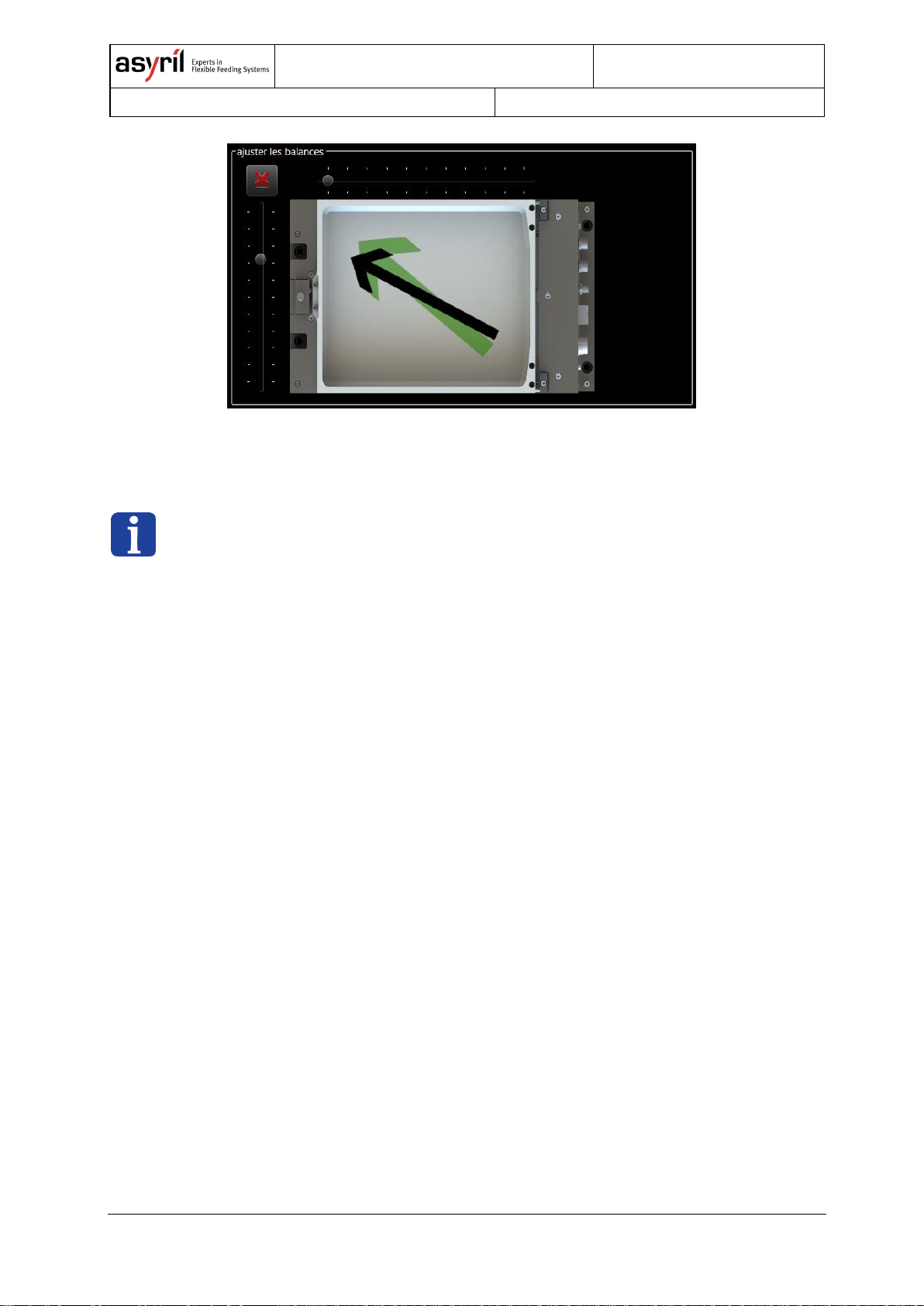
5.3. Asycube 240 & 380 & 530: Simplified adjustment method
"Easy-Tuning"
The system has a simplified adjustment method called “Easy-Tuning” applicable to all
parameters of Asycubes 240, 380 and 530. It is detailed in this section. This method involves
only the 11 standard vibrations (A – K).

Asycube
User Guide
© Copyright Asyril S.A.
000.101.029
Version: C
22/46
For each vibration, the number of adjustable parameters is reduced to the following five
parameters:
• 1 main amplitude (corresponds to the actuator(s) opposed to the target direction)
• 1 unique frequency (same for all actuators)
• 1 duration
• 2 balances to adjust the direction of displacement (fine adjustment of amplitude of all
actuators)
Figure 5-3: Asycube 240, 380 and 530 Easy-Tuning HMI
Balance “long side”
Balance “short side”
Main amplitude
Unique frequency
Duration
Theoretical movement
Programmed movement
Asycube
User Guide
© Copyright Asyril S.A.
000.101.029
Version: C
23/46
Figure 5-4: Example – Adjusting balance to correct a trajectory
NOTE:
Adjusting parameters in the Easy-Tune mode modifies the parameters in the ‘Platform’ and
‘Outputs’ tab. In certain cases, when the parameters are adjusted in the two latter tabs that
do not conform to the Easy-Tune mode (e.g. different frequencies for actuators), a warning
appears.

Asycube
User Guide
© Copyright Asyril S.A.
000.101.029
Version: C
24/46
6. Sequence
A sequence contains the different types of vibrations in order to feed, distribute, flip and orient
the components optimally on the picking surface. The sequence may vary depending on the
number of parts and their location on the platform in order to obtain optimal behaviour of
parts. This is the reason why the system may need data from the vision system such as the
number of parts on the platform (for feeding new parts onto the platform), their location (for
centring) and well-adjusted parameters of the vibration sets.
There are 26 sequences available and each of them is composed of up to seven actions. The
26 vibration sets are composed of the combination of the 26 platform vibrations and the 26
hopper vibrations/output activations. Any of the 26 sequences can be executed in
combination with any of the 26 vibration sets. This is useful in the case of different types of
parts (i.e. vibration sets) combined with various scenarios (i.e. sequences).
Please refer to the programming guide for more information on how to execute a sequence
using a certain vibration set.
Table 6-1 below gives the configuration options available to adjust a sequence. These
options are described in detail in the next section.
Action type
Vibration
Duration mode
Value
unit
Hopper/output
Hopper vibration/output
activation
(A – Z)
Fixed
Quantity adjusted
Vibration ratio
[ms]
[ms]
[%]
Platform
Platform vibration
(A – Z)
Fixed
Quantity adjusted
Vibration ratio
[ms]
[ms]
[%]
Smart vibration Centring
Maximum limit
[ms]
Wait
-
Fixed
[ms]
None
-
-
-
Table 6-1: Sequence options

Asycube
User Guide
© Copyright Asyril S.A.
000.101.029
Version: C
25/46
6.1. Actions
Four types of actions exist. The actions either concern the hopper/outputs, the platform or
none of the latter.
6.1.1. Hopper/output
Any of the 26 hopper vibrations/output activations (A – Z) of a vibration set can be selected in
order to feed parts onto the platform. By choosing between the three duration modes ‘Fixed’,
‘Quantity adjusted’ and ‘Vibration ratio’, the user can adjust the vibration duration of the
hopper in order to obtain different types of behaviour (see 6.2 Duration modes on page 26).
6.1.2. Platform
Any of the 26 platform vibrations (A – Z) of a vibration set can be selected in order to obtain
the desired part movement on the platform. By choosing between the three duration modes
‘Fixed’, ‘Quantity adjusted’ and ‘Vibration ratio’, the user can adjust the vibration duration of
the platform in order to obtain different types of behaviour (see 6.2 Duration modes on page
26).
Other than the platform vibrations, the user may select the smart vibration ‘Centring' which
centres parts no matter where they are located.
For a complete explanation of smart vibration ‘Centring' please refer to section 6.3.1 on page
27 of this document.
6.1.3. Wait
This action corresponds to a fixed waiting time given in ms. It is principally used between the
end of a vibration and before image acquisition in order to wait for the parts to stabilise on the
platform (i.e. to stop rolling/moving).
6.1.4. None
‘None’ corresponds to an empty action (non-programmed). This option is used for sequences
that do not require all of the seven available actions.

Asycube
User Guide
© Copyright Asyril S.A.
000.101.029
Version: C
26/46
6.2. Duration modes
When using an action related to a hopper vibration/output activation or a platform vibration,
the user may choose between three duration modes: 'Fixed', 'Quantity adjusted' or 'Vibration
ratio'. It can therefore adapt the behaviour of the system to the application.
6.2.1. ‘Fixed’
The duration mode ‘Fixed’ corresponds to the simplest configuration. The duration of the
vibration will always take the same amount of time, namely the value entered in the dialogue
box (in ms).
Figure 6-1: Duration mode ‘Fixed’ [ms]
6.2.2. ‘Quantity adjusted’
The duration mode ‘Quantity adjusted’ is mainly used to fulfil the function on feeding new
parts on the picking zone. In addition, it is considered a smart vibration, since its behaviour
adapts to the situation and hence depends on the data of a vision system.
Figure 6-2: ‘Quantity adjusted’ duration mode [ms]
For the additional explanation on the smart vibration ‘Quantity adjusted’, please refer to
section 6.3.1 on page 28 of this document.

Asycube
User Guide
© Copyright Asyril S.A.
000.101.029
Version: C
27/46
6.2.3. ‘Vibration ratio’
The ‘Vibration ratio’ duration mode links the vibration duration to use in the sequence with the
duration programmed in the vibration set. Entering the value 100% corresponds to the
vibration duration entered in the vibration set and therefore, if correctly adjusted, to the time
needed for the parts to fully cross the platform. Choosing 50% represents a partdisplacement of half the platform length. This considerably simplifies calculations for the user.
The other advantage is that when the user changes a vibration set, there is no need to
readjust the vibration durations in the sequence.
Figure 6-3: Duration mode ‘Vibration ratio’ [%]
IMPORTANT NOTE:
It is IMPORTANT to set the vibration duration as the time the parts need to completely
cross the platform in a given direction. The effectiveness of the ‘Centring' smart vibration
and ‘Vibration ratio’ duration mode depend on well-adjusted parameters.
6.3. Smart vibrations
A smart vibration adapts the vibration parameters depending on the situation. To do so it
needs the data from a vision system. The following sections provide a detailed explanation of
the two smart vibrations available: ‘Centring and ‘Quantity adjusted’.
6.3.1. ‘Centring’
In a sequence, the user may choose the action type on the platform in combination with a
Platform vibration (A – Z) or with the 'Centring' smart vibration. The latter determines the
optimal vibration direction and computes the vibration duration based on the data from a
vision system. The location of parts on the platform (centre of mass) is used to define the
direction and the distance to the centre. Once these two characteristics are determined, the
‘Centring’ vibration chooses:
• The adapted standard platform vibration
• The adapted vibration duration based on the given durations indicated in the vibration
set (i.e. the duration adjusted such that parts cross the entire platform)

Asycube
User Guide
© Copyright Asyril S.A.
000.101.029
Version: C
28/46
The duration mode of ‘Centring’ is called ‘Maximum limit’ and corresponds to the upper limit
of the vibration duration in this mode. Hence, the user limits the computed vibration duration
by entering a value in ms in the box. This is useful if your application engages a time
constraint that must be respected. If there is no special constraint, keep the default value of
10 seconds.
IMPORTANT NOTE:
It is IMPORTANT to set the vibration duration as the time the parts need to completely
cross the platform in a given direction. The effectiveness of the ‘Centring' smart vibration
and ‘Vibration ratio’ duration mode depends on well-adjusted parameters.
6.3.2. ‘Quantity adjusted’
The ‘quantity adjusted’ duration mode can be combined with hopper vibrations/output
activations or platform vibrations. This mode is mainly used for feeding new parts on the
picking zone. As is the case for the other smart vibration, the ‘quantity adjusted’ duration
mode is based on the data from a vision system (number of parts detected on the picking
zone).
The value entered in the dialogue box (in ms) corresponds to the vibration duration when
there are no parts on the platform. The more parts are detected, the less time the vibration
takes and when the upper limit of parts on the platform is reached, the vibration duration
decreases to zero. In between, the vibration duration is linearly interpolated. Note that the
user has to indicate the upper limit of parts in the dialogue box that appears when using
‘quantity adjusted’. This dialogue box is located after the seventh action.
Example:
Let's suppose that the upper limit of parts on the platform for the vibration is defined at 40
and the vibration duration entered in the box is 1000 ms. In the first case, no part is present
on the platform, the effective vibration duration is 1000 ms. In a second case where 20 parts
are detected on the platform, the effective vibration duration will be 500 ms. In the case
where 30 parts are detected on the platform, the effective vibration duration will be 250 ms.
When 40 or more parts are detected, there will be no further vibration.

Asycube
User Guide
© Copyright Asyril S.A.
000.101.029
Version: C
29/46
Figure 6-4: ‘Quantity adjusted’ duration mode [ms]
6.4. HMI simulation: Test sequence
In the Asyril HMI, it is possible to test a sequence, even without vision system data (number
of parts on the platform and their location). The three general situations are presented in this
section, the fourth is a mix between the first three.
6.4.1. Case 1: No smart vibration
No action of the sequence uses a smart vibration (i.e. no vision system). To execute the
simulation, simply press the large button representing the vibrating platform. Note that the
currently active vibration set is indicated in the upper left corner of the display. To select the
desired vibration set, simply change its ID in the ‘Platform’ or ‘Hopper’/‘Outputs’ tab.
Figure 6-5: HMI simulation case 1 – No smart vibration

Asycube
User Guide
© Copyright Asyril S.A.
000.101.029
Version: C
30/46
6.4.2. Case 2: ‘Quantity adjusted’
The duration mode ‘quantity adjusted’ adapts the vibration duration depending on the number
of parts detected on the picking zone. Besides indicating the vibration duration when no parts
are detected as well as the upper limit of parts when no new parts are to be fed, the user also
has to simulate a vision system by manually entering the number of parts located in the
picking zone in the simulation panel. Pushing the large button representing the platform
executes the test sequence.
Figure 6-6: HMI simulation case 2 – ‘Quantity adjusted’
6.4.3. Case 3: ‘Centring’
The ‘Centring' smart vibration needs the data from a vision system to centre the parts on the
platform. For the simulation, the user indicates the approximate location of the parts using
one of the nine buttons each representing a zone on the platform. Pushing one of the nine
buttons starts the test sequence.

Asycube
User Guide
© Copyright Asyril S.A.
000.101.029
Version: C
31/46
Figure 6-7: HMI simulation case 3 – ‘Centring'
6.4.4. Case 4: Mixed smart vibrations
Most situations require the combination of both smart vibrations: a feeding vibration
(hopper vibration/output activation) in ‘Quantity adjusted’ duration mode combined
with ‘Centring'. In this mixed case, the simulation interface is the combination of the
ones presented previously (Figure 6-6 and Figure 6-7).

Asycube
User Guide
© Copyright Asyril S.A.
000.101.029
Version: C
32/46
7. Saving
Only one of the 26 vibration sets can be active at a time. Before switching the vibration set ID
in the ‘Platform’ tab or the ‘Hopper’/‘Outputs’ tab, the user has to save the modifications
made in the “flash memory”, i.e. in the Asycube memory, or discard them (see Figure 7-1).
Also, note that flashing the parameters from the ‘Platform’ tab automatically flashes all the
parameters of the selected vibration set (i.e. including the parameters in the
‘Hopper’/‘Outputs’ tab) and likewise when flashing from the ‘Hopper’/‘Outputs’ tab.
Figure 7-1: Vibration set ID
Switching between sequences does not require flashing the parameters beforehand, you may
freely jump from a sequence to another and modify parameters. Also, note that a copy/paste
function is available not only to copy a whole sequence but also in the context of vibration
tuning.
Figure 7-2: Sequence ID and copy/paste function
Flashing the parameters, whether parameters of the vibration sets or the sequences, saves
them in the Asycube which means that they do not need loading from an external file.
Nevertheless, you can import/export .xml files via the HMI (see Table 7-1).
Figure 7-3: Import/export an .xml file

Asycube
User Guide
© Copyright Asyril S.A.
000.101.029
Version: C
33/46
Label
Content
Saving
.Fconf
Vibration set parameters such
as amplitude, frequency,
duration etc.
Only one vibration set can be saved in a .Fconf file at a
time.
.fseq
Sequence parameters such
as actions, vibrations,
duration values etc.
A sequence can either be saved individually, or all 26
sequences can be saved at once. Note that when
saving all the sequences, the sequence ID is saved.
Table 7-1: File formats
For more information on loading, saving and related commands please refer to the
programming guide for your Asycube.

Asycube
User Guide
© Copyright Asyril S.A.
000.101.029
Version: C
34/46
8. Backlight
The use of suitable lighting is an important factor for parts to be detected on the platform and
their orientation. All the Asycubes can be equipped with an integrated backlight. This chapter
summarises the different possibilities to activate the backlight as well as how to configure its
intensity.
8.1. Activation
There are two ways to activate the backlight illumination and to synchronise it with the image
acquisition (see Table 8-1).
Description
Method 1
Software commands:
a.) Command to switch ON and then command to
switch OFF
b.) Flashing-mode
Method 2
(recommended)
Hardware connection:
Using the backlight synchronisation input. The illumination time
corresponds to the impulse length.
Table 8-1: Backlight activation modes
When using both activation methods, the backlight will be ON if the command OR the signal
is activated.
Note that using a camera that is able to control the backlight of the Asycube (Method 2 –
Hardware connection) is more reliable in terms of timing than using software commands to
activate the Asycube backlight and then commands to a camera for image acquisition.
For more information on the commands related to the activation of the backlight, please refer
to the programming guide for your Asycube.
For more information on the electrical interface and connector reference of the backlight
synchronisation, please refer to the operating manual for your Asycube.
NOTE:
The backlight is optional and has to be ordered with your Asycube, as well as its colour.

Asycube
User Guide
© Copyright Asyril S.A.
000.101.029
Version: C
35/46
8.2. Intensity
The lighting intensity can be adjusted from a minimum given value to 100% using the slider in
the backlight tab of the HMI. The minimum intensity value can change from one Asycube
model to another. There is no need to flash this parameter manually as it is automatically
saved when modified. Also, note that this illumination level applies to both methods of
backlight activation described in Table 8-1.
Asycube
User Guide
© Copyright Asyril S.A.
000.101.029
Version: C
36/46
9. Example
This chapter presents a step-by-step example on how to work with the Asycube and
describes the concepts presented in the previous chapters. The order of the sections
respects the order of the general procedure presented in section 2.2 General procedure
overview on page 7 of this document.
9.1. Install and configure the Asyril HMI
Please refer to chapter 3 on page 11 of this document for the detailed and illustrated
procedure for installing the software.
9.2. Adjust platform and hopper vibrations
For each new part, follow the steps presented below. Note that usually, there is no need to
re-configure a completely new vibration set for each new part as it is possible to reuse
existing vibration sets. Therefore, a vibration set is usually connected to a family of parts
rather than a single version of a part. Also, vibration set 26 is a non-modifiable set of default
vibration parameters specifically set by Asyril for a standard part to work optimally on your
Asycube.
Please refer to chapter 4 on page 13 and chapter 5 on page 16 of this document for the
detailed explanation of the adjustable parameters and general adjustment advice.
9.2.1. Platform vibration
Step 1
Place a few parts on the Asycube platform, ideally the number of parts that seem to be
adequate (enough to be representative, not too many such as to minimise overlapping
parts).
Step 2
Test the behaviour of your parts on the Asycube either using vibration set number 26,
which contains the default parameters for a standard part (not modifiable by the user) or
by using one of your own parametrised vibration set.
If no adjusting is needed, you may skip steps 3 and 4.

Asycube
User Guide
© Copyright Asyril S.A.
000.101.029
Version: C
37/46
Step 3
There are different ways to start adjusting the parameters:
• Import an already configured vibration set (strongly encouraged)
Export a vibration set (for example vibration set 26) as an .Fconf file then import it
in the vibration set you assigned to your part type.
• Copy/paste a platform vibration
Method mainly used during the fine-tuning of the parameters of a vibration set.
Copy/paste option for one vibration at a time.
• Start tuning from zero (not recommended)
Some indications are given for the frequency range (references below).
Step 4
Adjust the parameters in order to obtain rapid and smooth part movement on the platform
and parts that jump only during the ‘Flip’ vibration. For coarse-tuning, you may take
advantage of continuous mode, which enables you to change parameters such as
frequency, amplitude etc. while the platform vibrates continuously. For fine-tuning, better
results are obtained when the vibration duration corresponds approximately to the real
situation.
• Part displacement vibrations (A – H):
Use the sinus signal.
1. Find an adequate frequency. Once the optimal frequency is found, you
may reuse the same frequency for adjusting the other platform vibrations.
2. Adjust the amplitude of the different actuators.
3. Adjust the vibration duration so that the parts completely cross the
platform in a given direction.
• ‘Flip’ vibration (I):
Use the sinus signal.
1. Find an adequate frequency.
(Asycube 50 & 80: See Table 5-2, Asycube 240, 380 and 530: See Table
5-3)
2. Adjust the amplitude.
3. Adjust the vibration duration; short, but enough time in order for the parts
to flip.
• Asycube 240, 380 and 530: ‘Long’- and ‘Short axis centring (J and K):
Use the sinus signal.
1. Find an adequate frequency.
(Asycube 240, 380 and 530: see Table 5-3)
2. Adjust the amplitude.
3. Adjust the duration.
Note that the procedure is identical when using the Easy-Tuning method, the adjusting
Asycube
User Guide
© Copyright Asyril S.A.
000.101.029
Version: C
38/46
interface is simplified as some parameters are regrouped.
Step 5
Troubleshooting:
• Trajectory deviation:
If parts do not move precisely enough towards the desired target, you may want to
correct the trajectory with help of the other actuators. (Asycube 50 & 80: See
section 5.1, Asycube 240, 380 and 530: See section 5.2 or use the balance slider
in the Easy-Tune mode).
• Invisible wall or obstacles:
For certain parameters, parts seem to encounter an invisible wall/obstacle or their
movement differs depending on their position on the platform. Test different
phases, this might help achieve a more steady movement.
Step 6
Make sure that the vibration duration for the standard platform vibrations corresponds to
the time the parts need to fully cross the platform. It is important to respect this; the
effectiveness of the Asycube depends on well-tuned parameters.
9.2.2. Hopper vibration/output activation
Step 1
Place parts in the hopper (homogeneous filling). When tuning parameters it is important
that the conditions are as close as possible to the production situation. Depending if your
parts are sticky or present the tendency to bundle, using a dam might be helpful.
Step 2
Perform the adjustments depending on your needs: You can either use a slower part
displacement in the hopper in order to obtain a better repeatability on the number of parts
fed (for the same vibration duration) or you can use a faster one, if you need a shorter
cycle.
• Asycube 50 & 80 (integrated hopper):
Adjust the frequency and amplitude.
• Asycube 240, 380 and 530:
Use the outputs to drive a hopper. You can select the output(s) that are active and
adjust signal amplitude from 0 to 100% (corresponding to 10 V) as well as the
duration of the signal. Please refer to the documentation for your specific hopper.

Asycube
User Guide
© Copyright Asyril S.A.
000.101.029
Version: C
39/46
9.3. Adjusting sequences
A sequence is used to combine different vibrations and usually corresponds to a scenario.
You can use different vibrations sets (i.e. types of parts) in combination with one or more
sequences. Three scenarios are discussed in this section:
1. Scenario - Flat platform: Feed and distribute parts
2. Scenario - Structured platform: Feed and pre-orient parts
3. Scenario - Flat platform: Distribute parts (Asycube 240, 380 and 530)
These scenarios are examples, you may be confronted with other scenarios and other
parameters may work better for your specific application. The goal here is to give you a
general idea on what you can do with sequences.
Please refer to chapter 6 for the explanation on sequences and more specifically the test
procedure for a sequence in section 6.4 page 29 of this document.
9.3.1. Flat platform: Feed and distribute parts
In the case of a flat platform, usually the ‘Centring' smart vibration followed by a ‘Flip’ is used
in order to distribute parts evenly on the platform.
Type
Vibration
duration mode
value
unit
1
Hopper/outp
ut
Forward
‘Quantity adjusted’
500
[ms]
2
Platform
Centring
Maximum limit
10,000
[ms]
3
Platform
Flip
Fixed
200
[ms]
4
Wait
-
Fixed
300
[ms]
Table 9-1: Example of scenario 1

Asycube
User Guide
© Copyright Asyril S.A.
000.101.029
Version: C
40/46
9.3.2. Structured platform: Feed and pre-orient parts
In the case of a structured platform, the goal is to sufficiently pre-orientate parts in grooves,
holes etc. such that the desired cycle time is obtained. In this case, the ‘Flip’ vibration is used
before smoother platform vibrations such as ‘Forward’ that enables the parts to be swept over
the structured platform. These sweeping vibrations may be very short or not even necessary
in some cases.
Type
Vibration
Duration mode
value
unit
1
Hopper/outp
ut
Forward
‘Quantity adjusted’
500
[ms]
2
Platform
Flip
Fixed
200
[ms]
3
Platform
Forward
Vibration ratio
100
[%]
4
Platform
Backward
Vibration ratio
50
[%]
5
Wait
-
Fixed
300
[ms]
Table 9-2: Example of scenario 2
Please refer to the operating manual for more information on structured platforms.
9.3.3. Flat platform: Distribute parts (Asycube 240, 380 and 530)
This example shows how to use a very simple sequence to centre the parts and distribute
them across the platform, available for Asycubes 240, 380 and 530 due to their two additional
standard platform vibrations: ‘Short axis centring' (J) and ‘Long axis centring' (K), which
enable the parts to be centred on the platform regardless of their position.
Type
Vibration
duration mode
value
unit
1
Platform
Long axis centring
Vibration ratio
100
[%]
2
Platform
Short axis centring
Vibration ratio
100
[%]
3
Platform
Flip
Fixed
3000
[ms]
4
Wait
-
Fixed
300
[ms]
Table 9-33: Example of scenario 3

Asycube
User Guide
© Copyright Asyril S.A.
000.101.029
Version: C
41/46
9.4. Save all the parameters in the Asycube
If not already done, save the parameters in the flash memory in the Asycube. If needed, it is
possible to export a vibration set or sequences as .xml files.
Please refer to chapter 7 on page 32 of this document for a detailed explanation on saving
procedures.
9.5. Configure the backlight
Please refer to chapter 8 on page 34 of this document for details on how to activate the
backlight and how to adjust its intensity.
NOTE:
For preliminary tests, it is sufficient to use the backlight activation button in the home tab of
the HMI or software commands (see next section).
9.6. Execute commands from PLC
A console mode is available in the Asyril HMI in order to test the communication with the
Asycube as well as the execution of commands as if they were sent from the client’s PLC
(Programmable Logic Controller).
NOTE:
The console mode can only be accessed with Integrator level access rights. Please refer to
the HMI user guide for more information on access rights.
Please refer to the programming guide for your Asycube for the full list of commands as well
as their detailed explanation.
Step 1
Use a vibration set
Command {UV1} Response {UV1}
Select vibration set 1.

Asycube
User Guide
© Copyright Asyril S.A.
000.101.029
Version: C
42/46
Step 2
Execute a sequence
Command {ES:(23;40;-1;1;5)} Response {ES:(23;40;-1;1;5; 1560)}
23 parts were detected on the picking zone, at 40 parts there is no feeding of new parts.
The location of the centre of mass of parts is located in the back left corner (x = -1, y = 1,
see Figure 9-1). The sequence to use is sequence 5. As a response, the system returns
the exact duration of the sequence (here 1560 ms).
Step 3
Backlight
Command {K1} Response {K1}
{K0} {K0}
Switching backlight ON (first command), then OFF.
The positions on the platform are normalised and defined as shown in Figure 9-1 below.
-1 / 1
1 / -1
-1 / -1
Plateforme
Trémie
Y
Figure 9-1: Normalized coordinate system on a platform
9.7. Control the Asycube from your PLC through Modbus
TCP
As an alternative to sending commands through TCP/IP, your PLC can control the Asycube
through Modbus TCP.

Asycube
User Guide
© Copyright Asyril S.A.
000.101.029
Version: C
43/46
NOTE:
The Modbus TCP communication interface is only available for Asycubes with a firmware
version greater than or equal to V4.0.0.
Please, refer to the programming guide for your Asycube for more information on Modbus
TCP and for the list of all Holding Registers in the Asycube register table.
Step 1
Use a vibration set
Change the value of the Holding Register HR_SELECT_VIBRATION_SET
Select vibration set 1: Set the value at 1.
Check which is the current vibration set
Read the value of the Holding Register HR_VIBRATION_SET_SELECTED
Step 2
Execute a sequence
1. Prepare the vibration parameters in HR_SEQUENCE_EXECUTION_NBPARTS,
HR_SEQUENCE_EXECUTION_NBMAX, HR_SEQUENCE_EXECUTION_X,
HR_SEQUENCE_EXECUTION_Y and
HR_SEQUENCE_EXECUTION_SEQUENCEID.
Example: 23, 40, -100, 100, 5.
2. Start the sequence by changing the value of the trigger
HR_SEQUENCE_EXECUTION_TRIG from 0 to 1.
23 parts were detected on the picking zone, at 40 parts there is no feeding of new parts.
The location of the centre of mass of parts is located in the back left corner (x = -1, y = 1,
see Figure 9-1). The sequence to use is sequence 5.
Monitor the execution sequence
Read the value of HR_MODBUS_SEQUENCE_STATUS and
HR_SEQUENCE_REMAINING_TIME.
Example: The HR_SEQUENCE_REMAINING_TIME register’s value will decrease from
the total duration (here 1560 ms) to 0. The HR_MODBUS_SEQUENCE_STATUS value
will change from 1 (BUSY) to 0 (DONE) as soon as the sequence is complete.
Step 3
Backlight
Switch ON: Change the value of HR_BACKLIGHT_STATE_CONTROL from 0 to 1
Switch OFF: Change the value of HR_BACKLIGHT_STATE_CONTROL from 1 to 0

Asycube
User Guide
© Copyright Asyril S.A.
000.101.029
Version: C
44/46
10. Technical support
10.1. For better service …
Have you read the relevant manuals and not found the answers to your questions? Before
calling the support service, note the following information for your system:
• Serial number and product key for your equipment
• Software version
• Alarm or error message displayed on the screen
10.2. Contact
A wealth of information is available on our website: www.asyril.com
You can also contact us by mail or call our support service:
support@asyril.com
+41 26 653 71 90

Asycube
User Guide
© Copyright Asyril S.A.
000.101.029
Version: C
45/46
Review history
Rev.
Date
Author
Comments
A
27.10.2016
PeA
Original version
A1
14.12.2016
HsJ
Modify figures and images for translation
B
17.08.2017
PeD
Addition of Asycube 530 and references to Modbus TCP
C
23.07.2019
PeD
Addition of Asycube 380 and various improvements

The following document is the property of Asyril S.A. and may not be copied or circulated
without permission. The information contained in this document is subject to change without
notice for the purpose of product improvement.
Asyril SA
Z.I. du Vivier 22
1690 Villaz-St-Pierre
Switzerland
Tel. +41 26 653 71 90
Fax +41 26 653 71 91
info@asyril.com
www.asyril.com
 Loading...