

Page 1
Doc. No:
Date: 2007.06.26
Revision:
ASUSTeK
COMPUTER INC.
M530w Assembly & Disassembly
SOP
Page: Grade:
Authorize
by
Review
by
Originator
by
Form No : D2-001-11 Rev.01
Rev. Modification
Modify description Issue div. Originator
V101 English CSC
M530w Assembly & Disassembly
SOP
Page 2
Doc. No:
ASUSTeK COMPUTER INC.
M530w Assembly & Disassembly
SOP
Date:
Rev.: Page:
1
Disassembly / Assembly procedure
Introduction
This section describes how to disassemble M530W telephone. Many of the integrated devices used in this
phone are vulnerable to damage. Ensure adequate static protection is in place when handling, shipping, and
servicing any internal components.
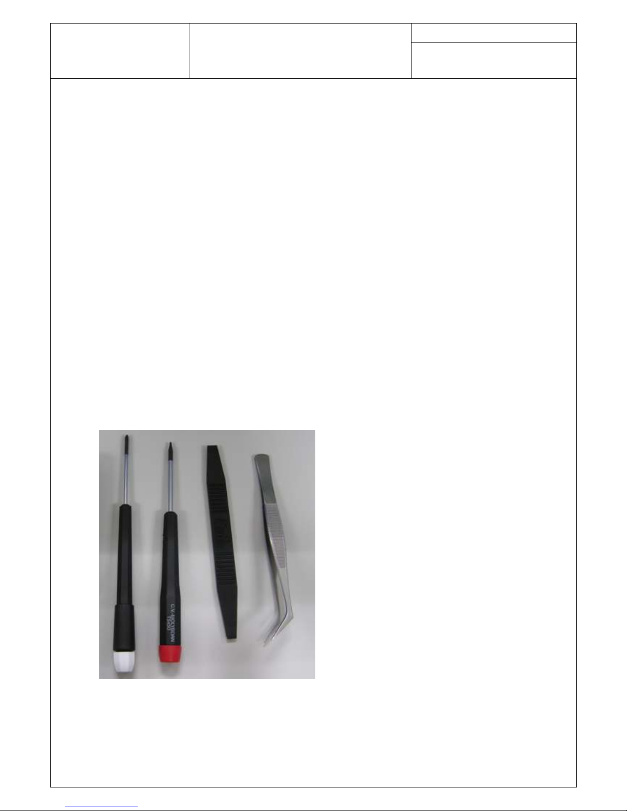
Recommended tools
Anti-Static Mat (Ground Cord included)
Anti-Static Wrist Strap
Torque Screw Driver (T5 type, torque is set to 1.2kg-cm)
Tweezers
Plastic blade
Page 3
Doc. No:
ASUSTeK COMPUTER INC.
M530w Assembly & Disassembly
SOP
Date:
Rev.: Page:
2
Disassembly procedure
The following set of diagrams will demonstrate the correct sequence and action to disassemble M530w.
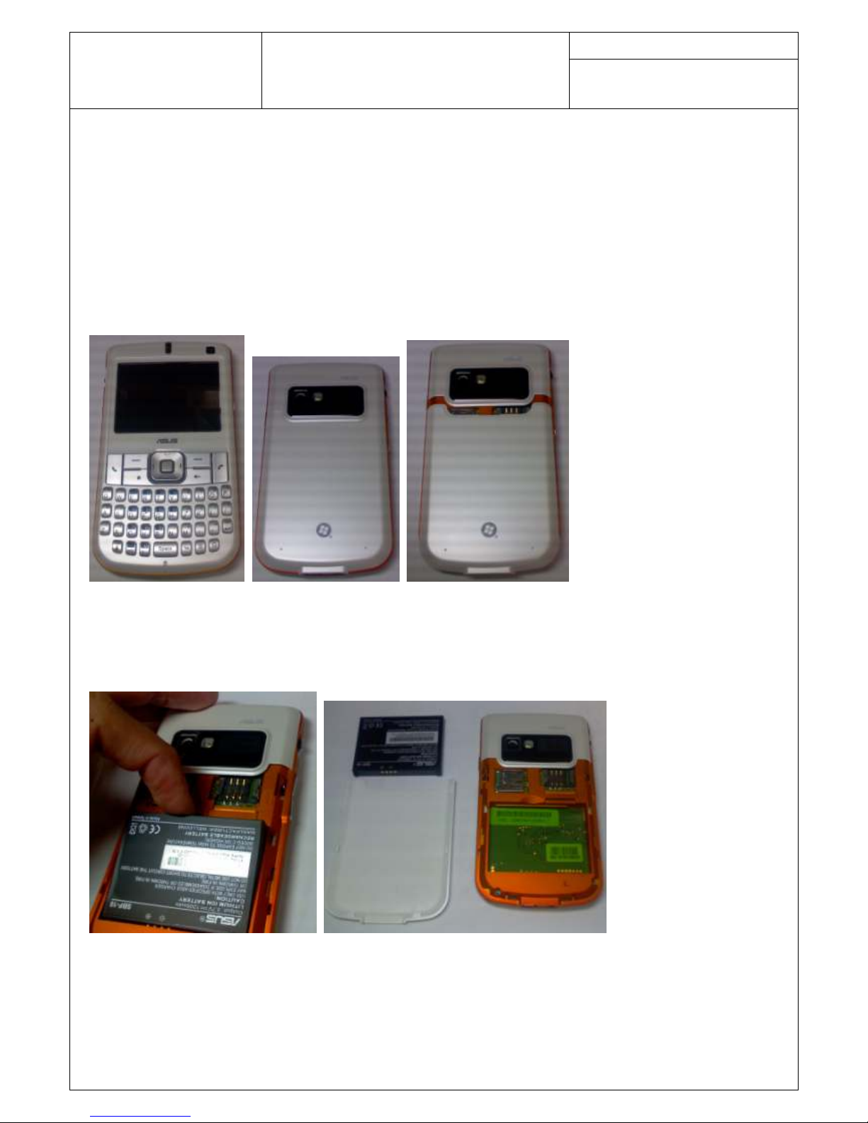
Step 1
Place M530w on the workbench and power it off.
Step 2
Remove the battery cover and take out the battery and SIM card. To remove the battery cover, press on the
battery cover on the bottom of the phone.
Remove the battery.
Page 4
Doc. No:
ASUSTeK COMPUTER INC.
M530w Assembly & Disassembly
SOP
Date:
Rev.: Page:
3
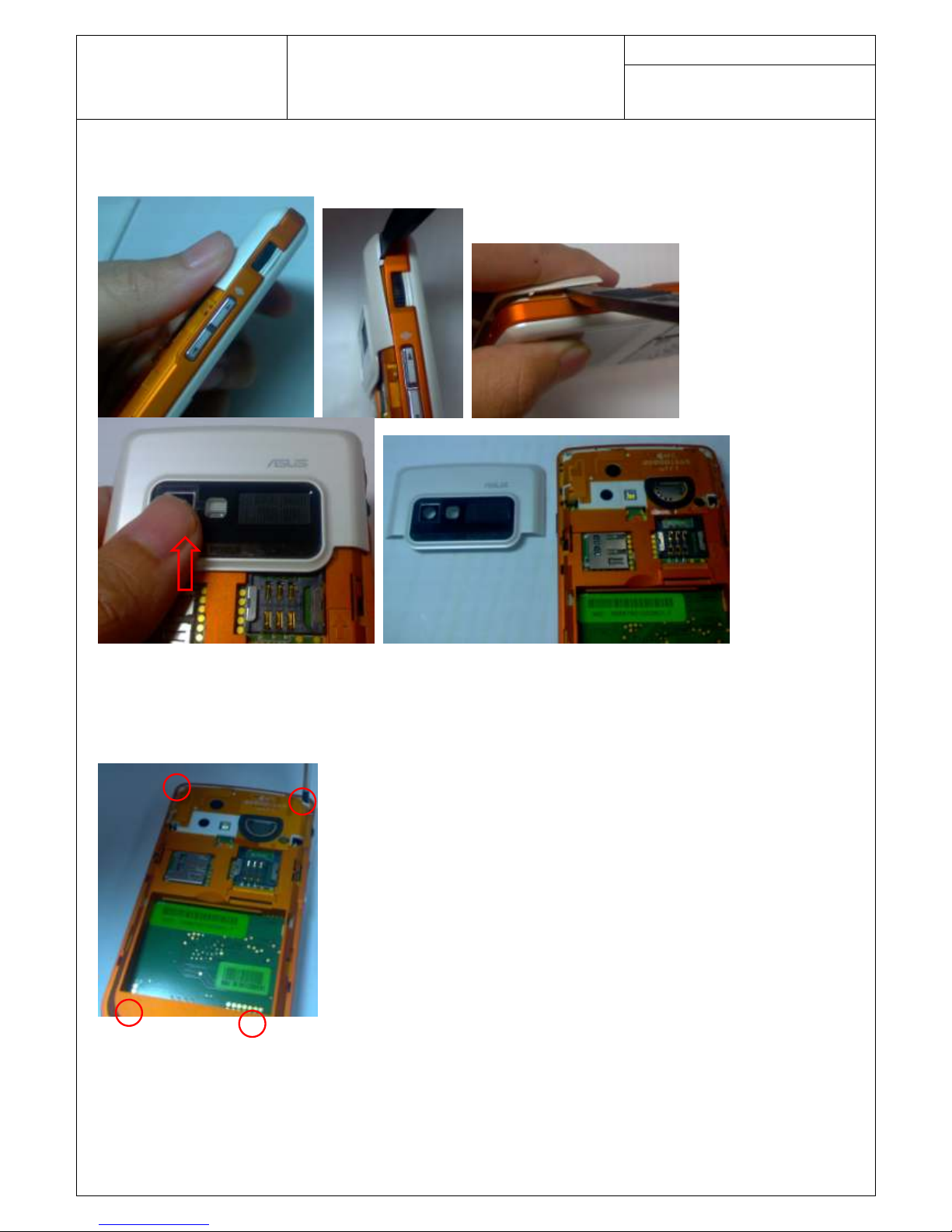
Step 3
Remove M530w RF Cover ASSY by Plastic blade.
Step 4
Remove 4*Screw M1.6*4L T5 by Screw Driver.
Page 5

Doc. No:
ASUSTeK COMPUTER INC.
M530w Assembly & Disassembly
SOP
Date:
Rev.: Page:
4
Remove the Front Case and Bottom Case ASSY by Plastic blade.
Step 5
Remove receiver, Vibrator and Antenna Rubber from Bottom Case by Tweezers.
Page 6

Doc. No:
ASUSTeK COMPUTER INC.
M530w Assembly & Disassembly
SOP
Date:
Rev.: Page:
5
Step 6
Remove 2*Screw M1.7*3.3L T5 by Screw Driver from Main Board.
Remove 2*Screw M1.6*4L T5 by Screw Driver from WIFI Board and release the WIFI Coaxial Cable.
Page 7

Doc. No:
ASUSTeK COMPUTER INC.
M530w Assembly & Disassembly
SOP
Date:
Rev.: Page:
6
Step 7
Remove the VGA CMOS CAMERA MODULE.
Remove the 2.0M AM CAMERA.
Step 8
Remove the LCM FPC Hard Mylar and release the connector of LCM by tweezers.
Step 9
Remove receiver by tweezers from Front Case.
Page 8

Doc. No:
ASUSTeK COMPUTER INC.
M530w Assembly & Disassembly
SOP
Date:
Rev.: Page:
7
Step 10
Remove Keypad FPC ASSY by Tweezers.
Step11
Remove M530w EN QWERTY KEY.
Step12
Remove LCM module from Case1.
Page 9

Doc. No:
ASUSTeK COMPUTER INC.
M530w Assembly & Disassembly
SOP
Date:
Rev.: Page:
8
Assembly procedure
It is carried out in the exact reverse sequence as the disassembly.
Step1
Assemble the LCM module from Case1.
Step2
Assemble M530w EN QWERTY KEY and Keypad FPC ASSY.
Step 3
Assemble the receiver by tweezers.
Page 10

Doc. No:
ASUSTeK COMPUTER INC.
M530w Assembly & Disassembly
SOP
Date:
Rev.: Page:
9
Step 4
Assemble the 2.0M AM CAMERA and the VGA CMOS CAMERA MODULE.
Step 5
Connect the WIFI Coaxial Cable and Assemble WIFI Board with 2*Screw M1.6*4L T5 by Screw Driver.
Put on the microphone rubber.
Page 11

Doc. No:
ASUSTeK COMPUTER INC.
M530w Assembly & Disassembly
SOP
Date:
Rev.: Page:
10
Step 6
Put on WIFI Board with 2*Screw M1.7*3.3L T5 by Screw Driver in the Main Board.
Step 7
Put on receiver, Vibrator and Antenna Rubber from Bottom Case by Tweezers.
Step 8
Put on Bottom Case with 4*Screw M1.6*4L T5 by Screw Driver.
Page 12

Doc. No:
ASUSTeK COMPUTER INC.
M530w Assembly & Disassembly
SOP
Date:
Rev.: Page:
11
Step 9
Assemble the M530w RF Cover ASSY.
Step 10
Put the battery and Battery cover in the bottom of the phone.
 Loading...