

Page 1
Doc. No:
Date: 2008.9.23
Revision:
ASUSTeK
COMPUTER INC.
Galaxy mini 5 Assembly &
Disassembly SOP
Page: Grade:
Authorize
by
Review
by
Originator
by
Form No : D2-001-11 Rev.01
Rev. Modification
Modify description Issue div. Originator
V101 English CSC
Galaxy mini 5 Assembly & Disassembly
SOP
Page 2
Doc. No:
ASUSTeK COMPUTER INC.
Galaxy mini 5 Assembly &
Disassembly SOP
Date:
Rev.: Page:
1
Disassembly / Assembly Procedure
Introduction
This section describes how to disassemble PDA GM2. Many of the integrated devices used in
this phone are vulnerable to damage. Ensure adequate static protection is in place when
handling, shipping, and servicing any internal components.
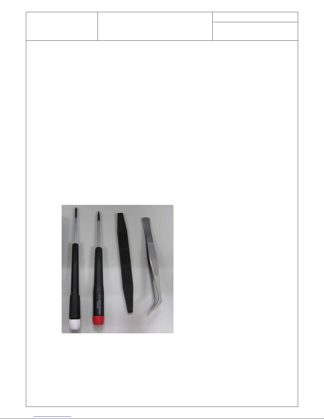
Recommended Tools
Anti-Static Mat (Ground Cord included)
Anti-Static Wrist Strap
Torque Screw Driver (T5 type, torque is set to 1.2kg-cm)
Tweezers
Plastic blade
Page 3
Doc. No:
ASUSTeK COMPUTER INC.
Galaxy mini 5 Assembly &
Disassembly SOP
Date:
Rev.: Page:
2
Disassembly procedure
The following set of diagrams will demonstrate the correct sequence and action to disassemble P565.
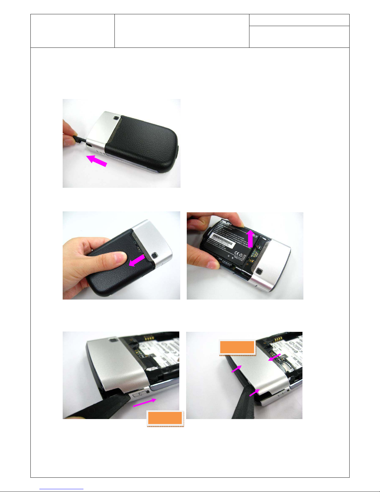
Step 1
Take the stylus away from the PDA PHONE.
Step 2
Remove the battery case and take the battery away.
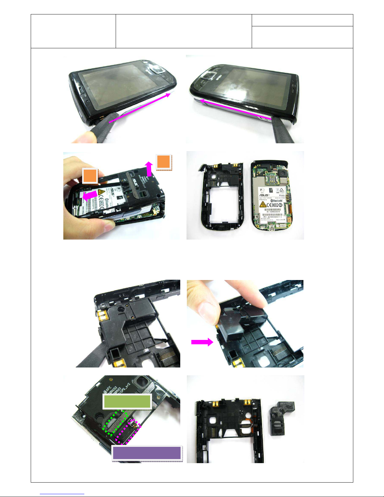
Step 3
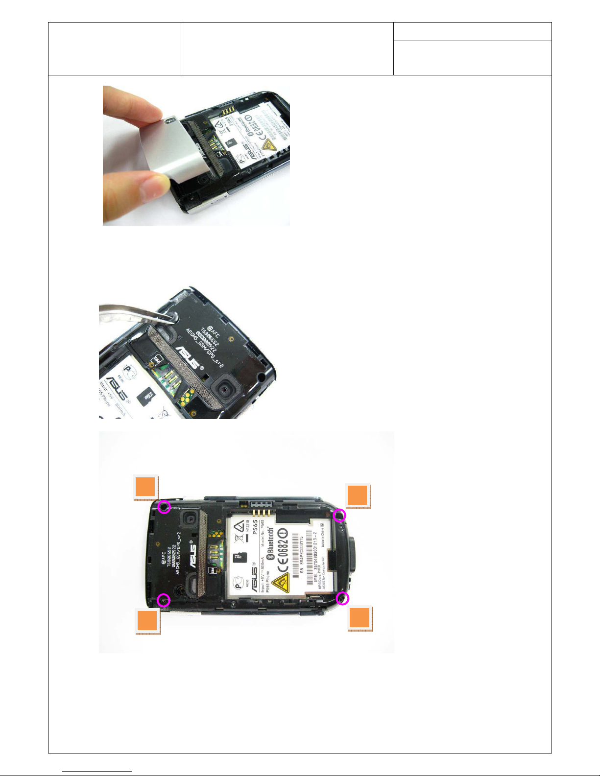
Pry the edges of the RF cover. Pay attention to the hooks in the cover. Then remove the RF cover
from the device.
Hooks
Hooks
Page 4
Doc. No:
ASUSTeK COMPUTER INC.
Galaxy mini 5 Assembly &
Disassembly SOP
Date:
Rev.: Page:
3
Step 4
Remove the antenna rubber. And remove 4 screws on the middle case assy. Then remove the
middle case assy from the I/O side.
1
3
2
4
Page 5
Doc. No:
ASUSTeK COMPUTER INC.
Galaxy mini 5 Assembly &
Disassembly SOP
Date:
Rev.: Page:
4
Step 5
Pry the speaker box by a plastic blade and then remove the speaker box.
Pay attention to the
speaker net and the GSM/GPS antenna on the middle case assy. Do not tear them up when removing
the speaker box.
1
2
Speaker Set
GPS/GSM Antenna
Page 6
Doc. No:
ASUSTeK COMPUTER INC.
Galaxy mini 5 Assembly &
Disassembly SOP
Date:
Rev.: Page:
5
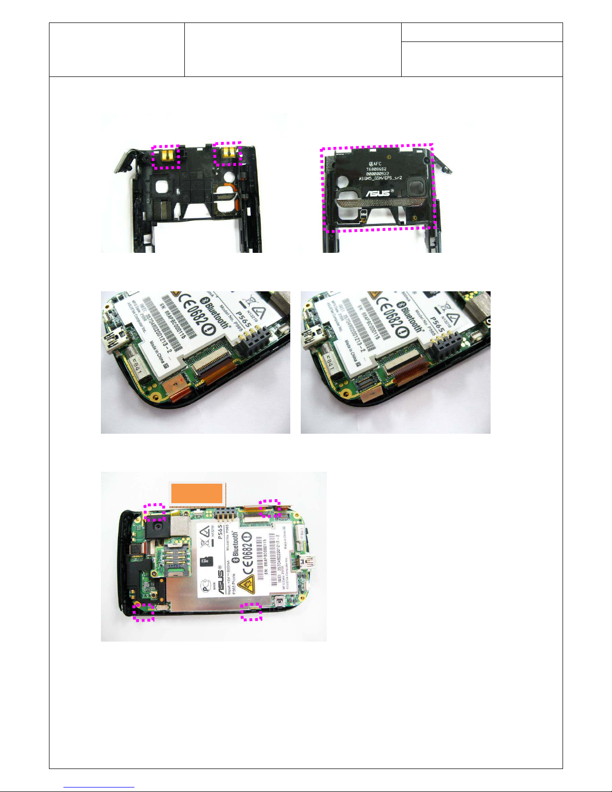
Step 6
Carefully tear off the GSM/GPS antenna on the middle case assy.
Step 7
Disconnect the LCD panel FPC and keypad FPC from the main board.
Step 8
Separate the main board from the top case assy.
Release the main board from the hooks first.
Hooks
Page 7

Doc. No:
ASUSTeK COMPUTER INC.
Galaxy mini 5 Assembly &
Disassembly SOP
Date:
Rev.: Page:
6
Step 9
Remove 2 screws on the SIM board and then remove the SIM board.
Step 10
Separate the CMOS camera module from the SIM board. Then disassemble the camera rubbers.
2
1
Page 8

Doc. No:
ASUSTeK COMPUTER INC.
Galaxy mini 5 Assembly &
Disassembly SOP
Date:
Rev.: Page:
7
Step11
Remove the speaker box rubber. Open the VGA camera connector and remove the VGA camera.
Then remove the MIC rubber.
Page 9

Doc. No:
ASUSTeK COMPUTER INC.
Galaxy mini 5 Assembly &
Disassembly SOP
Date:
Rev.: Page:
8
Step12
Open the touch lens FPC connector and remove the keypad FPC. Then remove the keypad.
Step13
Release the LCD panel from the hooks and then remove the panel from the top case assy. Remove
the receiver from the top case assy.
Touch Lens FPC
Hooks
Page 10

Doc. No:
ASUSTeK COMPUTER INC.
Galaxy mini 5 Assembly &
Disassembly SOP
Date:
Rev.: Page:
9
Page 11

Doc. No:
ASUSTeK COMPUTER INC.
Galaxy mini 5 Assembly &
Disassembly SOP
Date:
Rev.: Page:
10
Assembly Procedure
It is carried out in the exact reverse sequence as the disassembly.
Step 1
Install the receiver on the front cover by a pair of tweezers. Then install the LCD panel.
Step 2
Assemble the keypad. Connect the touch lens FPC with the keypad FPC and install the keypad
FPC in the top case.
Hooks
Page 12

Doc. No:
ASUSTeK COMPUTER INC.
Galaxy mini 5 Assembly &
Disassembly SOP
Date:
Rev.: Page:
11
Step 3
Install the MIC rubber. Assemble the VGA camera and close its connector on the main board.
Install the speaker box rubber.
Touch Lens FPC
Page 13

Doc. No:
ASUSTeK COMPUTER INC.
Galaxy mini 5 Assembly &
Disassembly SOP
Date:
Rev.: Page:
12
Step 4
Assemble the camera rubbers with the CMOS camera. Then install the CMOS camera on the SIM
board.
Step 5
Install the SIM board with the main board. Then secure 2 screws on the SIM board.
Page 14

Doc. No:
ASUSTeK COMPUTER INC.
Galaxy mini 5 Assembly &
Disassembly SOP
Date:
Rev.: Page:
13
Step 6
Install the main board and arrange it in the hooks of the top case assy.
Step 7
Connect the LCD FPC and close its connector. Then connect the keypad FPC.
2
1
Hooks
Page 15

Doc. No:
ASUSTeK COMPUTER INC.
Galaxy mini 5 Assembly &
Disassembly SOP
Date:
Rev.: Page:
14
Step 8
Carefully paste the GSM/GPS antenna on the middle case assy and arrange it well.
Step 9
Install the speaker box in the middle case assy.
Step 10
Engage the middle case assy from the I/O side. Switch the “Hold” key on the main board and on
the middle case to the same direction. Then connect the middle case with the device and press it
well.
I/O Side
Page 16

Doc. No:
ASUSTeK COMPUTER INC.
Galaxy mini 5 Assembly &
Disassembly SOP
Date:
Rev.: Page:
15
Step 11
Secure 4 screws on the middle case assy and then install the antenna rubber.
3
Page 17

Doc. No:
ASUSTeK COMPUTER INC.
Galaxy mini 5 Assembly &
Disassembly SOP
Date:
Rev.: Page:
16
Step 12
Install the RF cover and press four sides to fix the cover.
Step 13
Install the battery and the battery cover. Slide on the battery cover.
Step 14
Then insert stylus.
 Loading...