

Page 1
Doc. No:
Date:
ASUSTeK COMPUTER A63x Assembly & Disassembly
Revision:
INC.
Guide
Page: Grade:
Authorize
by
Review
by
Originator
by
Jonathan
Rev. Modification Modify description Issue div. Originator
V101 English 1 X #1 Phillips-head Screwdriver Jonathan
V101 English 1 X T-5 Torx Screwdriver
V101 English 1 X Plastic Knife
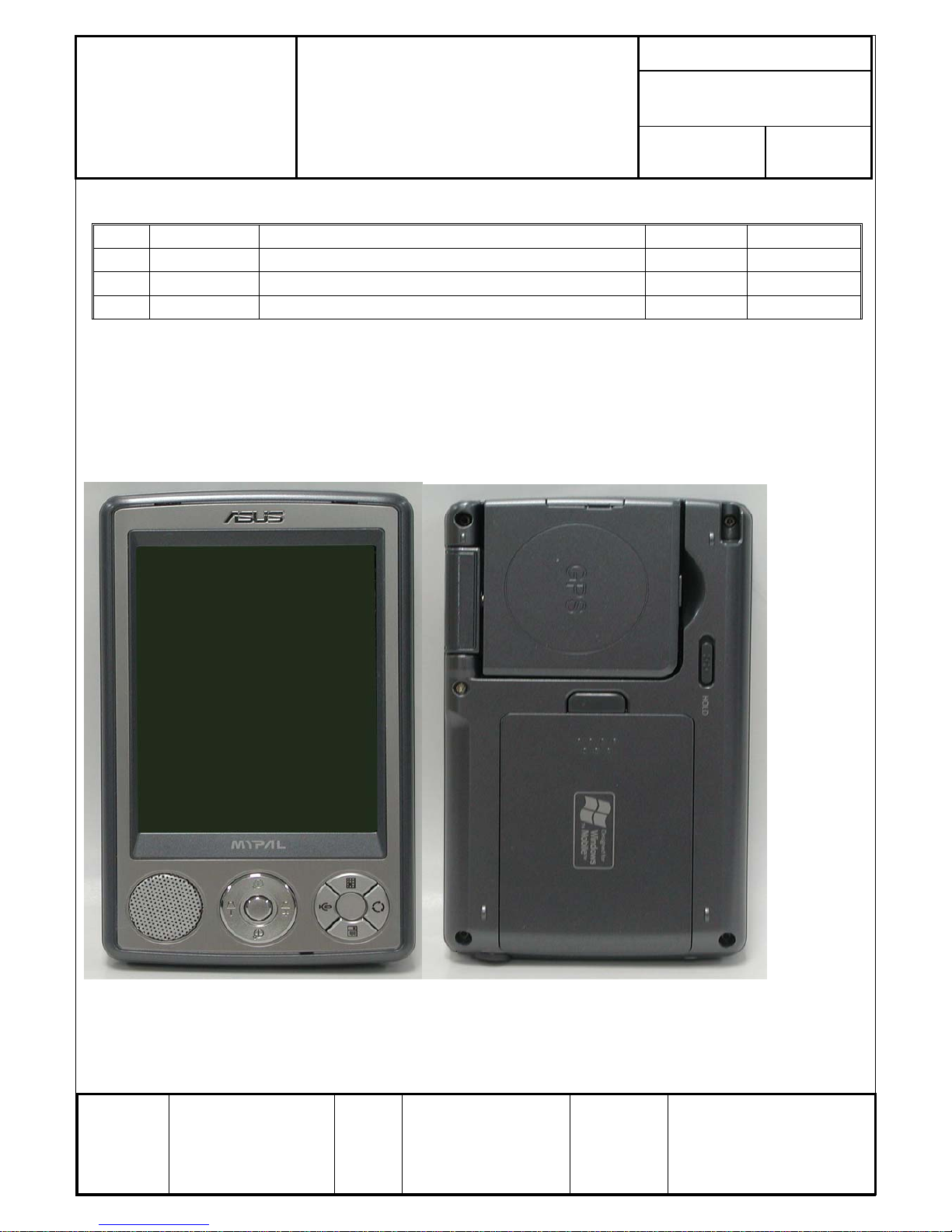
Purpose:
This SOP is separated into three parts:(1)Overview(2) Disassembly(3) Assembly。
This purpose of this SOP is to help engineer assemble & disassemble more easily。
1. Overview
2. Disassembly
Form No : D2-001-11 Rev.01
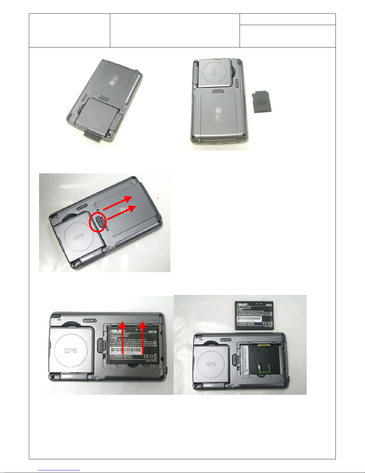
1. Remove SD card (PIC1.1, PIC1.2)
Page 2
Doc. No:
ASUSTeK COMPUTER INC.
A63x Assembly & Disassembly
Date:
Rev.: Page:
1
Guide
PIC1.1 PIC1.2
2. Remove the battery cover by pressing the release button and pull back. (PIC2.1)
PIC2.1
3. Remove the battery. (PIC3.1, PIC3.2)
PIC3.1 PIC3.2
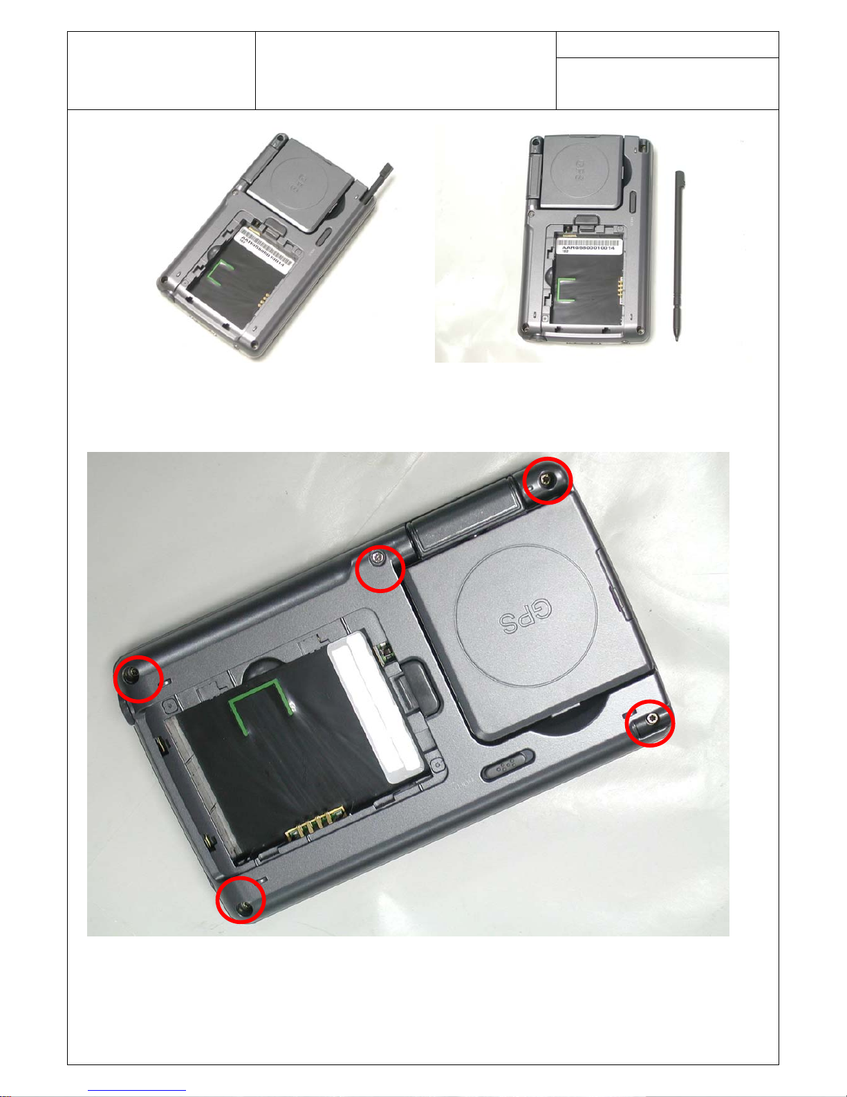
4. Remove Stylus. (PIC4.1, PIC 4.2)
Page 3
Doc. No:
ASUSTeK COMPUTER INC.
A63x Assembly & Disassembly
Date:
Rev.: Page:
2
Guide
PIC4.1 PIC4.2
5. Remove 5 screws (PIC5.1)
PIC5.1
6. Separate the retaining hook with plastic knife. (PIC6.1, PIC6.2)
Page 4
Doc. No:
ASUSTeK COMPUTER INC.
A63x Assembly & Disassembly
Date:
Rev.: Page:
3
Guide
PIC6.1 PIC6.2
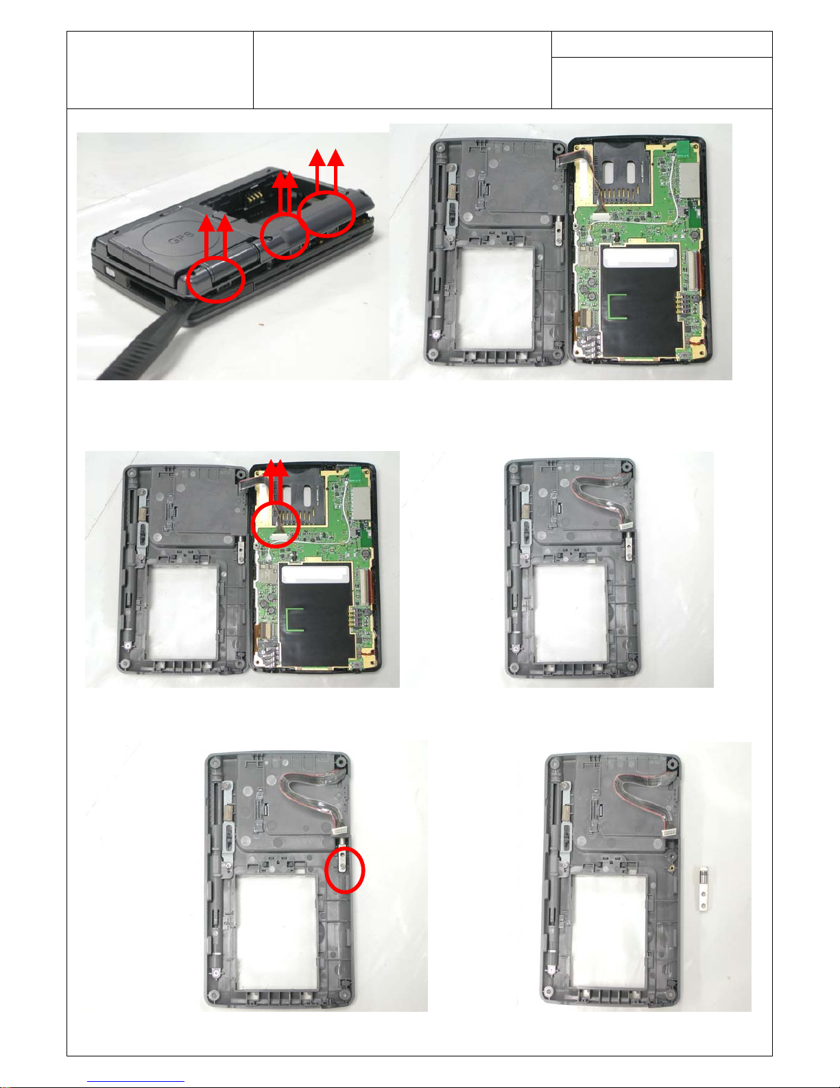
7. Slowly pull up connector cable (PIC7.1, PIC7.2)
PIC7.1 PIC7.2
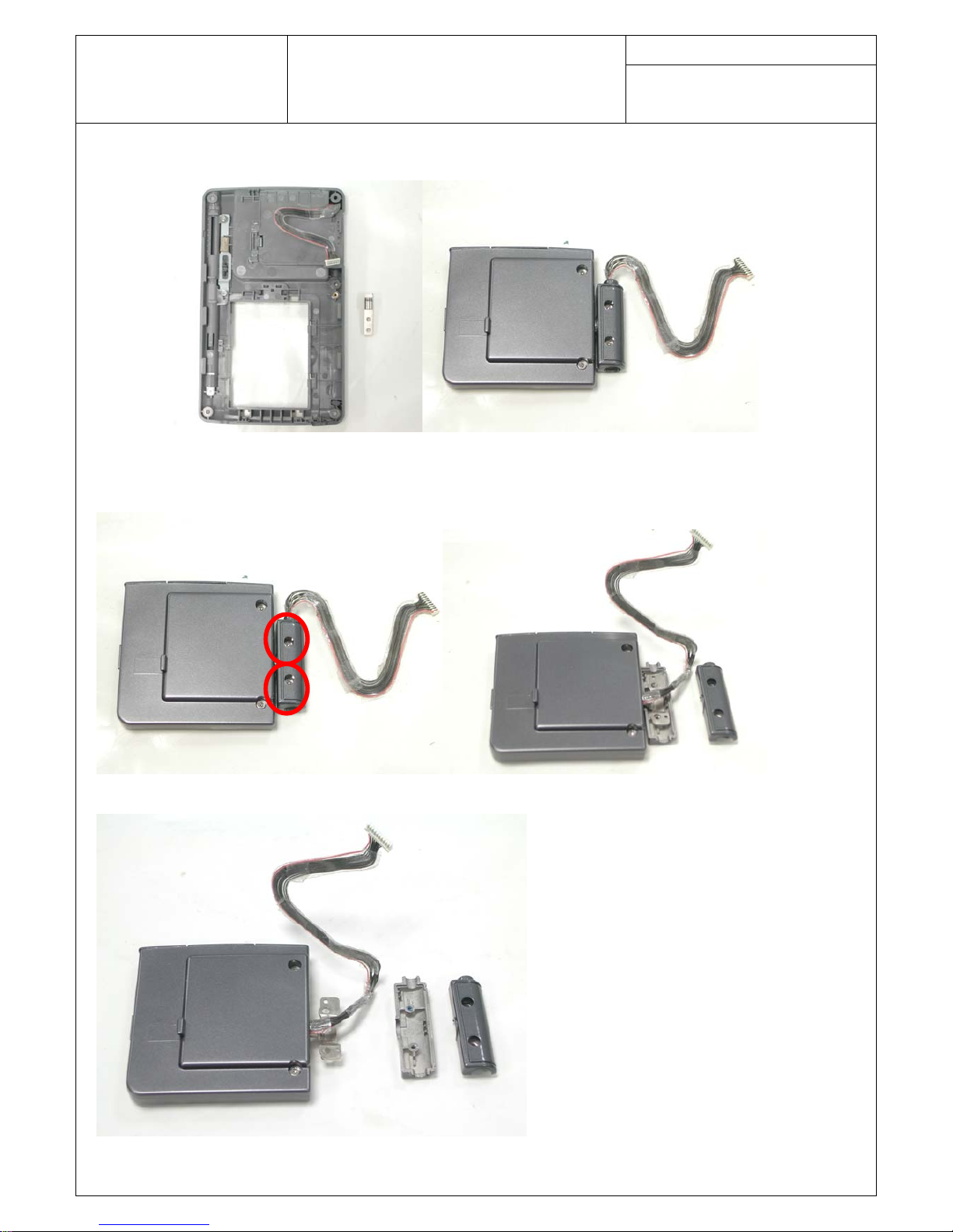
8. Remove 1 screw and hinge (PIC8.1, PIC8.2)
PIC8.1 PIC8.2
Page 5
Doc. No:
ASUSTeK COMPUTER INC.
A63x Assembly & Disassembly
Date:
Rev.: Page:
4
Guide
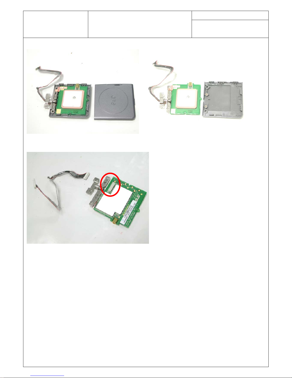
9. Remove GPS module (PIC9.1, PIC9.2)
PIC9.1 PIC9.2
10. Remove 2 screws and both cover (PIC10.1, PIC10.2, PIC10.3)
PIC10.1 PIC10.2
PIC10.3
Page 6
Doc. No:
ASUSTeK COMPUTER INC.
A63x Assembly & Disassembly
Date:
Rev.: Page:
5
Guide
11. Remove top and bottom cover of GPS module. (PIC11.1, PIC11.2)
PIC11.1 PIC11.2
12. Remove cable here. (PIC12.1)
PIC12.1
13. Remove LCD FPC, KEYPAD FPC and Audio connector. (PIC13.1, PIC13.2)
Page 7

Doc. No:
ASUSTeK COMPUTER INC.
A63x Assembly & Disassembly
Date:
Rev.: Page:
6
Guide
PIC13.1
PIC13.2
14. Remove the main board module. (PIC14.1, PIC14.2)
Page 8

Doc. No:
ASUSTeK COMPUTER INC.
A63x Assembly & Disassembly
Date:
Rev.: Page:
7
Guide
PIC14.1 PIC14.2
15. Remove 2 screws and speaker holder (PIC15.1, PIC15.2)
PIC15.1 PIC15.2
16. Remove Speaker (PIC16.1, PIC16.2)
Page 9

Doc. No:
ASUSTeK COMPUTER INC.
A63x Assembly & Disassembly
Date:
Rev.: Page:
8
Guide
PIC16.1 PIC16.2
17. Remove Keypad module. (PIC17.1, PIC17.2)
PIC17.1 PIC17.2
18. Remove Keypad (PIC18.1, PIC18.2)
PIC18.1 PIC18.2
Page 10

Doc. No:
ASUSTeK COMPUTER INC.
A63x Assembly & Disassembly
Date:
Rev.: Page:
9
Guide
19. Remove LCD (PIC19.1, PIC19.2)
PIC19.1
PIC19.2
Page 11

Doc. No:
ASUSTeK COMPUTER INC.
A63x Assembly & Disassembly
Date:
Rev.: Page:
10
Guide
3. Assembly
1. Assemble LCD (PIC1.1, PIC1.2)
PIC1.1
PIC1.2
2. Assemble Keypad (PIC2.1, PIC2.2)
Page 12

Doc. No:
ASUSTeK COMPUTER INC.
A63x Assembly & Disassembly
Date:
Rev.: Page:
11
Guide
PIC2.1 PIC2.2
3. Assemble Keypad module. (PIC3.1, PIC3.2)
PIC3.1 PIC3.2
4. Assemble Speaker (PIC4.1, PIC4.2)
PIC4.1 PIC4.2
5. Assemble speaker holder and 2 screws (PIC5.1, PIC5.2)
Page 13

Doc. No:
ASUSTeK COMPUTER INC.
A63x Assembly & Disassembly
Date:
Rev.: Page:
12
Guide
PIC5.1 PIC5.2
6. Assemble the main board module. (PIC6.1, PIC6.2)
PIC6.1 PIC6.2
7. Assemble LCD FPC, KEYPAD FPC and Audio connector. (PIC7.1, PIC7.2)
Page 14

Doc. No:
ASUSTeK COMPUTER INC.
A63x Assembly & Disassembly
Date:
Rev.: Page:
13
Guide
PIC7.1
PIC7.2
8. Assemble cable here. (PIC8.1)
Page 15

Doc. No:
ASUSTeK COMPUTER INC.
A63x Assembly & Disassembly
Date:
Rev.: Page:
14
Guide
PIC8.1
9. Assemble top and bottom cover of GPS module. (PIC9.1, PIC9.2)
PIC9.1 PIC9.2
10. Remove 2 screws and both cover (PIC10.1, PIC10.2, PIC10.3)
PIC10.1 PIC10.2
Page 16

Doc. No:
ASUSTeK COMPUTER INC.
A63x Assembly & Disassembly
Date:
Rev.: Page:
15
Guide
PIC10.3
11. Assemble GPS module (PIC11.1, PIC11.2)
PIC11.1 PIC11.2
12. Assemble hinge and screw (PIC12.1, PIC12.2)
PIC12.1 PIC12.2
13. Slowly insert connector cable (PIC13.1, PIC13.2)
Page 17

Doc. No:
ASUSTeK COMPUTER INC.
A63x Assembly & Disassembly
Date:
Rev.: Page:
16
Guide
PIC13.1 PIC13.2
14. Assemble the cover and secure 5 screws (PIC14.1, PIC14.2)
PIC14.1 PIC14.2
15. Assemble Stylus (PIC15.1, PIC 15.2)
PIC15.1 PIC15.2
Page 18

Doc. No:
ASUSTeK COMPUTER INC.
A63x Assembly & Disassembly
Date:
Rev.: Page:
17
Guide
16. Insert the battery. (PIC16.1, PIC16.2)
PIC16.1 PIC16.2
17. Assemble battery cover (PIC17.1)
PIC17.1
18. Insert SD card (PIC18.1, PIC18.2)
PIC18.1 PIC18.2
 Loading...