

Page 1
User Guide
ZenWiFi AX Hybrid ZenWiFi AX Hybrid
AX1800+ AV1300 Dual-band Powerline AX1800+ AV1300 Dual-band Powerline
Mesh WiFi6 RouterMesh WiFi6 Router
Model: XP4Model: XP4
Page 2

E18547
First Edition
June 2021
Copyright © 2021 ASUSTeK Computer Inc. All Rights Reserved.
No part of this manual, including the products and software described
in it, may be reproduced, transmitted, transcribed, stored in a retrieval
system, or translated into any language in any form or by any means, except
documentation kept by the purchaser for backup purposes, without the
express written permission of ASUSTeK Computer Inc. (“ASUS”).
Product warranty or service will not be extended if: (1) the product is repaired,
modied or altered, unless such repair, modication of alteration is authorized
in writing by ASUS; or (2) the serial number of the product is defaced or
missing.
ASUS PROVIDES THIS MANUAL “AS IS” WITHOUT WARRANTY OF ANY KIND,
EITHER EXPRESS OR IMPLIED, INCLUDING BUT NOT LIMITED TO THE IMPLIED
WARRANTIES OR CONDITIONS OF MERCHANTABILITY OR FITNESS FOR A
PARTICULAR PURPOSE. IN NO EVENT SHALL ASUS, ITS DIRECTORS, OFFICERS,
EMPLOYEES OR AGENTS BE LIABLE FOR ANY INDIRECT, SPECIAL, INCIDENTAL,
OR CONSEQUENTIAL DAMAGES (INCLUDING DAMAGES FOR LOSS OF PROFITS,
LOSS OF BUSINESS, LOSS OF USE OR DATA, INTERRUPTION OF BUSINESS
AND THE LIKE), EVEN IF ASUS HAS BEEN ADVISED OF THE POSSIBILITY OF
SUCH DAMAGES ARISING FROM ANY DEFECT OR ERROR IN THIS MANUAL OR
PRODUCT.
SPECIFICATIONS AND INFORMATION CONTAINED IN THIS MANUAL ARE
FURNISHED FOR INFORMATIONAL USE ONLY, AND ARE SUBJECT TO CHANGE
AT ANY TIME WITHOUT NOTICE, AND SHOULD NOT BE CONSTRUED AS A
COMMITMENT BY ASUS. ASUS ASSUMES NO RESPONSIBILITY OR LIABILITY
FOR ANY ERRORS OR INACCURACIES THAT MAY APPEAR IN THIS MANUAL,
INCLUDING THE PRODUCTS AND SOFTWARE DESCRIBED IN IT.
Products and corporate names appearing in this manual may or may not be
registered trademarks or copyrights of their respective companies, and are used
only for identication or explanation and to the owners’ benet, without intent
to infringe.
2
Page 3

Table of contents
1 Getting to know your wireless router
1.1 Welcome! ...........................................................................................6
1.2 Package contents ...........................................................................6
1.3 Your wireless router .......................................................................7
1.4 Positioning your router ................................................................9
1.5 Setup Requirements ................................................................... 10
1.6 Router Setup ................................................................................. 11
2 Getting started
2.1 Installing ASUS Router App ..................................................... 14
2.1.1 Quick Internet Setup (QIS) with ASUS Router App ...14
2.2 Logging into the Web GUI ........................................................ 18
2.2.1 Quick Internet Setup (QIS) with Web GUI .....................19
2.3 Connecting to your wireless network .................................. 23
3 Conguring the General settings
3.1 Using the Network Map ........................................................... 24
3.1.1 Setting up the wireless security settings ...................... 25
3.1.2 Managing your network clients ....................................... 26
3.1.3 Monitoring your USB device ............................................. 27
3.1.4 Setting up AiMesh System ................................................. 30
3.2 Creating a Guest Network ........................................................ 33
3.3 AiProtection................................................................................... 35
3.3.1 Network Protection .............................................................. 36
3.3.2 Setting up Parental Controls .............................................40
3.4 Using the Trac Manager ........................................................ 43
3.4.1 Managing QoS (Quality of Service) Bandwidth..........43
3.5 Using the USB Application ....................................................... 45
3.5.1 Using AiDisk ............................................................................ 45
3.5.2 Using Servers Center ............................................................47
3
Page 4

Table of contents
3.5.3 3G/4G ........................................................................................52
3.6 Using AiCloud 2.0 ........................................................................ 54
3.6.1 Cloud Disk ................................................................................ 55
3.6.2 Smart Access ........................................................................... 56
3.6.3 AiCloud Sync ........................................................................... 57
4 Conguring the Advanced Settings
4.1 Wireless ........................................................................................... 58
4.1.1 General ...................................................................................... 58
4.1.2 WPS ............................................................................................61
4.1.3 Bridge ........................................................................................ 64
4.1.4 Wireless MAC Filter ............................................................... 66
4.1.5 RADIUS Setting ...................................................................... 67
4.1.6 Professional .............................................................................69
4.2 LAN ................................................................................................... 72
4.2.1 LAN IP ........................................................................................ 72
4.2.2 DHCP Server ............................................................................73
4.2.3 Route .........................................................................................75
4.2.4 IPTV ............................................................................................ 76
4.3 WAN .................................................................................................. 77
4.3.1 Internet Connection .............................................................77
4.3.2 Dual WAN ................................................................................. 79
4.3.3 Port Trigger .............................................................................. 81
4.3.4 Virtual Server / Port Forwarding ...................................... 83
4.3.5 DMZ............................................................................................86
4.3.6 DDNS .........................................................................................87
4.3.7 NAT Passthrough ................................................................... 88
4
Page 5

Table of contents
4.4 IPv6 ................................................................................................... 89
4.5 Firewall ............................................................................................ 90
4.5.1 General ...................................................................................... 90
4.5.2 URL Filter ..................................................................................90
4.5.3 Keyword lter .........................................................................91
4.5.4 Network Services Filter .......................................................92
4.6 Administration.............................................................................. 94
4.6.1 Operation Mode .................................................................... 94
4.6.2 System .......................................................................................95
4.6.3 Firmware Upgrade ................................................................97
4.6.4 Restore/Save/Upload Setting ...........................................97
4.7 System Log .................................................................................... 98
5 Utilities
5.1 Device Discovery ......................................................................... 99
5.2 Firmware Restoration ................................................................. 99
6 Troubleshooting
6.1 Basic Troubleshooting .............................................................101
6.2 Frequently Asked Questions (FAQs) ..................................104
Appendices
Notices .......................................................................................................113
Service and Support ..............................................................................150
5
Page 6

1 Getting to know your wireless 1 Getting to know your wireless
routerrouter
1.1 Welcome!
Thank you for purchasing an ASUS ZenWiFi AX Hybrid Wireless
Router!
The ultra-thin and stylish ZenWiFi AX Hybrid features a 2.4GHz
and 5GHz dual bands for an unmatched concurrent wireless HD
streaming; SMB server, UPnP AV server, and FTP server for 24/7
le sharing; a capability to handle 300,000 sessions; and the ASUS
Green Network Technology, which provides up to 70% powersaving solution.
1.2 Package contents
ZenWiFi AX Hybrid Wireless Router Network cable (RJ-45)
Power cable Quick Start Guide
NOTES:
• If any of the items are damaged or missing, contact ASUS for
technical inquiries and support. Refer to the ASUS Support Hotline
list at the back of this user manual.
• Keep the original packaging material in case you would need future
warranty services such as repair or replacement.
6
Page 7
1.3 Your wireless router
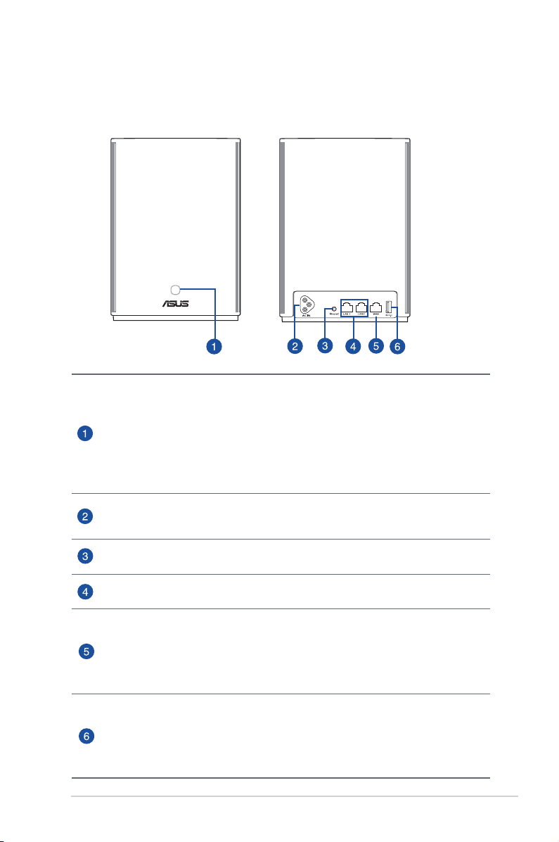
ASUS ZenWiFi AX Hybrid Overview
WPS/PLC combo button
Press this button to start WPS or PLC pairing.
WPS pairing: Press the buttons on XP4 and a new wireless client to establish
WiFi connection.
PLC pairing: Press the buttons on XP4 in the existing Mesh System and a new
XP4 device. After a short time, the new XP4 device will be integrated into your
existing Mesh System.
AC power connector
Connect your router and node to wall sockets using the bundled power cords.
Reset button
This button resets or restores the system to its factory default settings.
LAN ports
Connect network cables into these ports to establish LAN connection.
WAN port
Connect a network cable into this port to establish WAN connection.
If you use XP4 as an AiMesh node, you can connect a network cable from a
LAN port of an AiMesh router to its WAN port for uplink connection of Ethernet
backhaul.
USB 3.1 Gen1 port
Insert a USB 3.1 Gen 1/ USB 2.0 device such as a USB disk or USB 3G/4G modem
into this port.
If you use XP4 as an AiMesh node, the USB port supports function of AiDisk
and macOS backup.
7
Page 8

Specications
DC Power adapter 100-240V AC, 50/60Hz, 1A
Operating Temperature 0~40oC Storage 0~70oC
Operating Humidity 50~90% Storage 20~90%
ZenWiFi AX Hybrid LED indications
Solid blue
Your AiMesh router or node is ready for setup.
Solid white
Your AiMesh router or node is online and works well.
Solid amber
The signal between your AiMesh router and the node is weak.
Solid red
Your AiMesh router has no Internet connection.
Your AiMesh node is disconnected from the router.
Blinking blue
Your AiMesh router is applying new settings.
Blinking amber
Your AiMesh router or node is resetting.
Solid purple
Your AiMesh router or node is in rescue mode.
Solid green
Your AiMesh router or node is switching to another channel caused by system
rebooting or radar signals detected on the current channel.
8
Page 9
1.4 Positioning your router
For the best wireless signal transmission between the wireless
router and the network devices connected to it, ensure that you:
• Place the wireless router in a centralized area for a maximum
wireless coverage for the network devices.
• Keep the device away from metal obstructions and away from
direct sunlight.
• Keep the device away from 802.11g or 20MHz only Wi-Fi
devices, 2.4GHz computer peripherals, Bluetooth devices,
cordless phones, transformers, heavy-duty motors, uorescent
lights, microwave ovens, refrigerators, and other industrial
equipment to prevent signal interference or loss.
• Always update to the latest rmware. Visit the ASUS website at
http://www.asus.com to get the latest rmware updates.
9
Page 10

1.5 Setup Requirements
To set up your wireless network, you need a computer that meets
the following system requirements:
• Ethernet RJ-45 (LAN) port (10Base-T/100Base-TX/
1000BaseTX)
• IEEE 802.11a/b/g/n/ac wireless capability
• An installed TCP/IP service
• Web browser such as Internet Explorer, Firefox, Safari, or
Google Chrome
NOTES:
• If your computer does not have built-in wireless capabilities, you may
install an IEEE 802.11a/b/g/n/ac WLAN adapter to your computer to
connect to the network.
• With its dual band technology, your wireless router supports 2.4GHz
and 5GHz wireless signals simultaneously. This allows you to do
Internet-related activities such as Internet surng or reading/writing
e-mail messages using the 2.4GHz band while simultaneously
streaming high-denition audio/video les such as movies or music
using the 5GHz band.
• Some IEEE 802.11n devices that you want to connect to your network
may or may not support 5GHz band. Refer to the device's manual for
specications.
• The Ethernet RJ-45 cables that will be used to connect the network
devices should not exceed 100 meters.
10
Page 11

1.6 Router Setup
IMPORTANT!
• Use a wired connection when setting up your wireless router to
avoid possible setup problems.
• Before setting up your ASUS wireless router, do the following:
• If you are replacing an existing router, disconnect it from your
network.
• Disconnect the cables/wires from your existing modem setup. If
your modem has a backup battery, remove it as well.
• Reboot your cable modem and computer (recommended).
11
Page 12
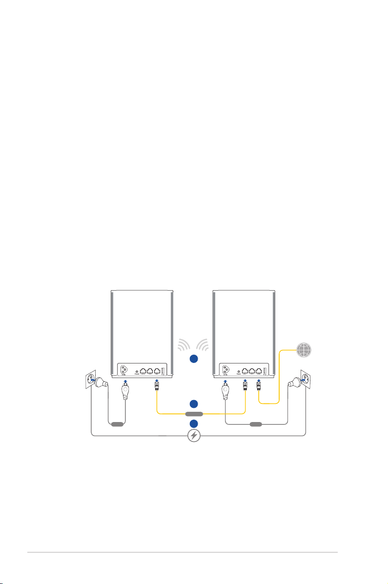
AiMesh Router Setup Steps
XP4 works as an AiMesh router by default. You can also add
01
it to an existing AiMesh system as an AiMesh node.
• As an AiMesh router: Use a network cable to connect
your modem to the WAN port of XP4. (Skip to Step
02)
• As an AiMesh node:
Place the node within 3 meters
of the router during the setup process. Connect
your AiMesh node to the AiMesh router via the
following ways:
A. WiFi Backhaul connection (Skip to Step 02).
B. Ethernet Backhaul connection: Connect an
Ethernet cable from the LAN port of the AiMesh
router to the WAN port of the AiMesh node.
C. Powerline Backhaul connection (Skip to Step 02).
12
AiMesh Node
Use XP4 as a node
A
B
WAN-LAN
Power Power
C
AiMesh Router
Use XP4 as a router
Page 13

02
Connect XP4 to a wall socket using the bundled power cord.
NOTES:
• Do not use a power extension cord to avoid degrading
HomePlug signal and reducing data transfer speeds.
• To minimize powerline interference, connect the power cord
to a wall socket directly.
• Plug the power cord to a 3-prong outlet instead of a 2-prong
one for higher data transfer speeds.
Wait until the LED turns solid blue indicating that the device
03
is ready for the setup.
Enable Bluetooth on your phone and launch ASUS Router
04
APP. Do either of the following and follow the onscreen
instructions to nish the AiMesh setup.
Press Set up a new network if you use XP4 as an AiMesh
router; or
Press Add AiMesh node if you use XP4 as an AiMesh node.
NOTE: To set the AiMesh router to Access Point mode, go to web
GUI (http://router.asus.com), and go to the page Administration >
Operation Mode.
13
Page 14
2 Getting started2 Getting started
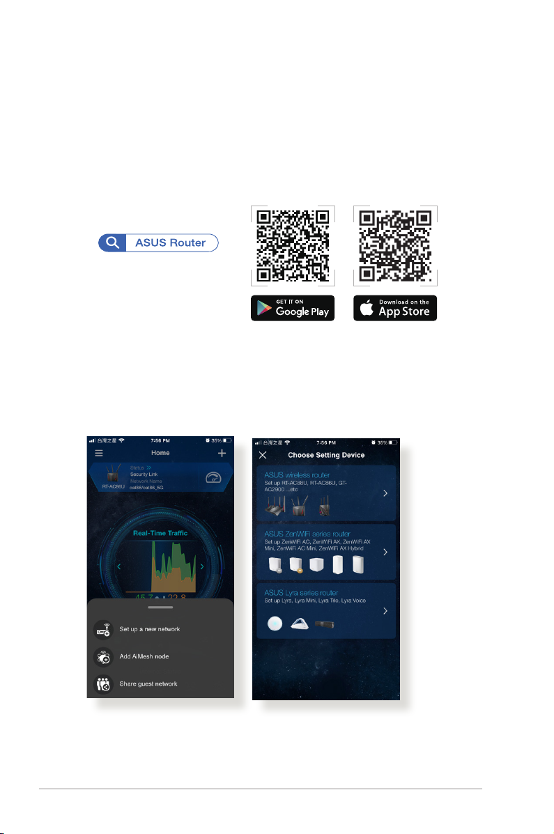
2.1 Installing ASUS Router App
Download free ASUS Router app to set up and manage your
router(s).
2.1.1 Quick Internet Setup (QIS) with ASUS Router App
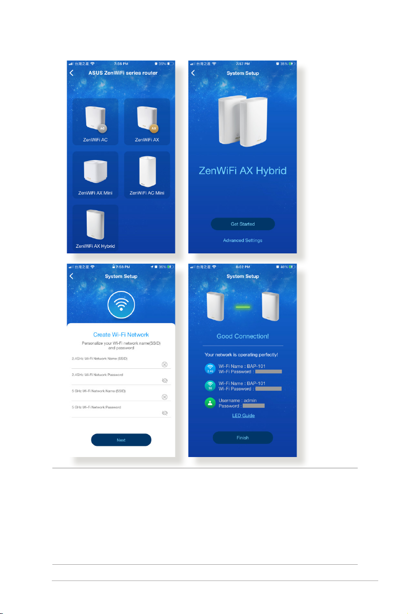
Open the ASUS Router app and follow the on-screen instructions
to set up your network.
14
Page 15
NOTES:
• If you have trouble nding your routers, ensure that the router and
node are far enough away from each other. Interference from routers
can complicate the setup process.
• When setting up the SSID, you can select Separate 2.4GHz and
5GHz to assign dierent SSIDs for your wireless bands.
15
Page 16
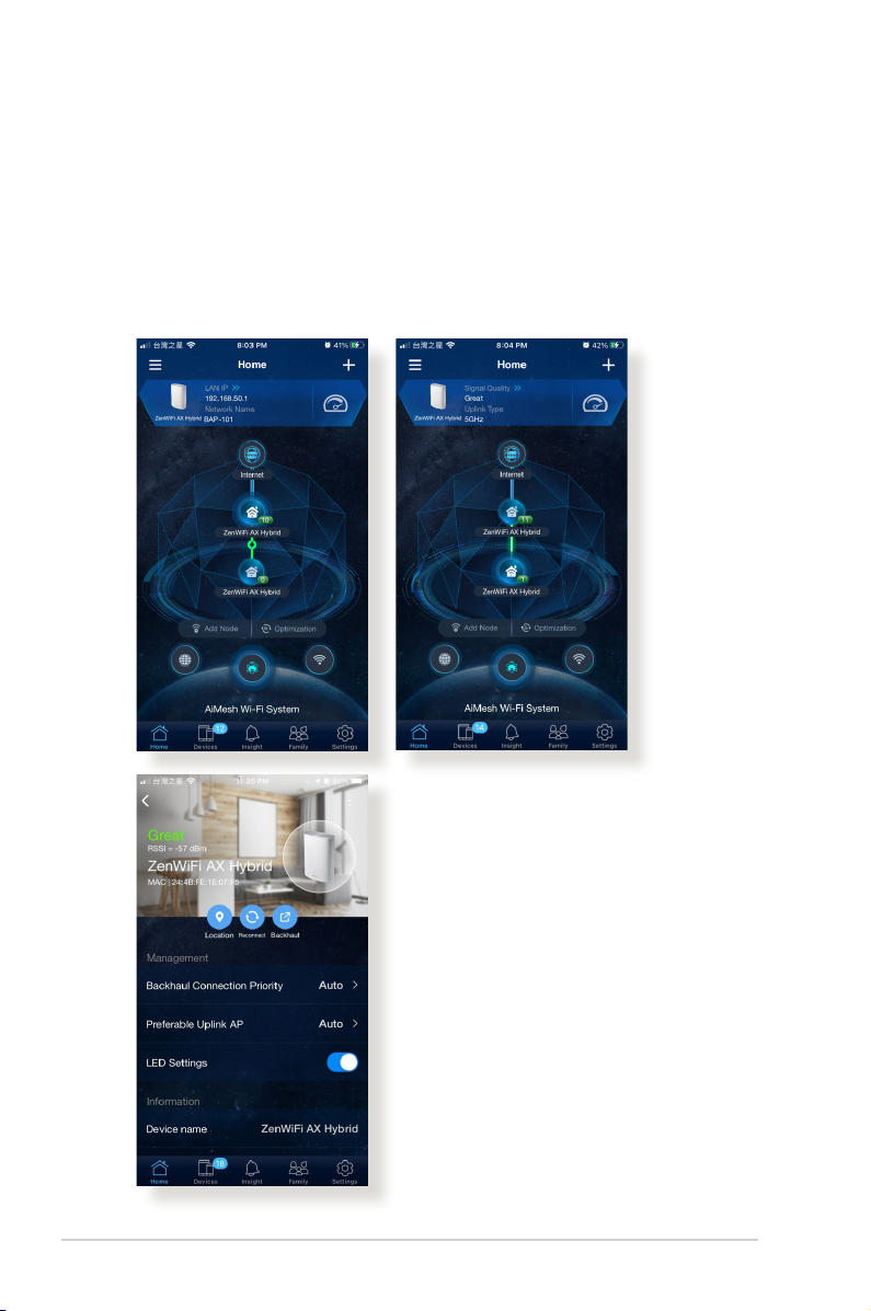
To ensure that your router and node have been set up properly,
in the ASUS Router app, go to Home and check the network
connection between the router and the node.
• A green bar between the two nodes indicates strong signal
strength;
• Tap the node to check the signal strength or connection
quality.
16
Page 17

After the node has connected, the router LED indicator may
turn green, indicating that the router is performing backend
optimizations. At this time, devices can connect to the network,
but performance may be limited. We recommend waiting to
perform tests until the router LED indicator turns white.
You can go to the router’s web GUI for additional congurations if
necessary. Refer to the following pages for details.
17
Page 18
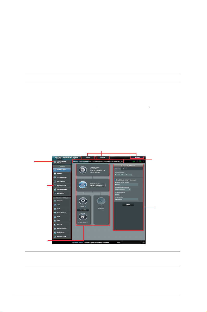
2.2 Logging into the Web GUI
Your ASUS Wireless Router comes with an intuitive web graphical
user interface (GUI) that allows you to easily congure its various
features through a web browser such as Internet Explorer, Firefox,
Safari, or Google Chrome.
NOTE: The features may vary with dierent rmware versions.
To log into the web GUI:
1. On your web browser, enter http://router.asus.com.
2. On the login page, key in the default user name (admin) and
password (admin).
3. You can now use the Web GUI to congure various settings of
your ASUS Wireless Router.
Top command buttons
QIS
Navigation
panel
middle
column
Information
banner
right column
NOTE: If you are logging into the Web GUI for the rst time, you will be
directed to the Quick Internet Setup (QIS) page automatically.
18
Page 19

2.2.1 Quick Internet Setup (QIS) with Web GUI
The Quick Internet Setup (QIS) function guides you in quickly
setting up your Internet connection.
NOTE: When setting the Internet connection for the rst time, press
the Reset button on your wireless router to reset it to its factory default
settings.
To use QIS with auto-detection:
1. Log into the Web GUI. The QIS page launches automatically.
NOTES:
• For details on changing your wireless router's login username and
password, refer to section 4.6.2 System.
• The wireless router's login username and password is dierent from
the 2.4GHz/5GHz network name (SSID) and security key. The wireless
router's login username and password allows you to log into your
wireless router's Web GUI to congure your wireless router's settings.
The 2.4GHz/5GHz network name (SSID) and security key allows Wi-Fi
devices to log in and connect to your 2.4GHz/5GHz network.
19
Page 20
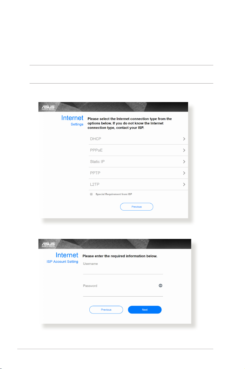
2. The wireless router automatically detects if your ISP connection
type is Dynamic IP, PPPoE, PPTP, L2TP, and Static IP. Key in
the necessary information for your ISP connection type.
IMPORTANT! Obtain the necessary information from your ISP about
the Internet connection type.
for Automatic IP (DHCP)
for PPPoE, PPTP, and L2TP
20
Page 21
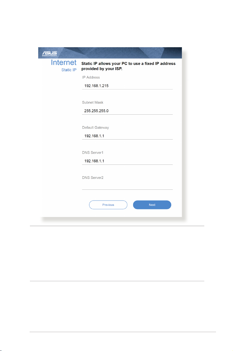
for Static IP
NOTES:
• The auto-detection of your ISP connection type takes place when
you congure the wireless router for the rst time or when your
wireless router is reset to its default settings.
• If QIS failed to detect your Internet connection type, click Skip to
manual setting and manually congure your connection settings.
3. Assign the wireless network name (SSID) and security key for
your 2.4 GHz and 5 GHz wireless connection. Click Apply when
done.
21
Page 22
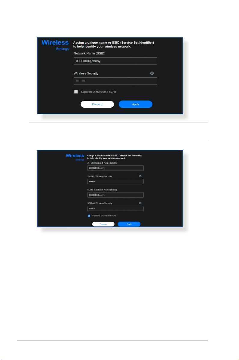
NOTE: If you want to assign dierent SSIDs for your 2.4 GHz and 5 GHz
wireless connection, tick Separate 2.4GHz and 5 GHz.
22
Page 23

2.3 Connecting to your wireless network
After setting up your wireless router via QIS, you can connect your
computer or other smart devices to your wireless network.
To connect to your network:
1. On your computer, click the network icon in the notication
area to display the available wireless networks.
2. Select the wireless network that you want to connect to, then
click Connect.
3. You may need to key in the network security key for a secured
wireless network, then click OK.
4. Wait while your computer establishes connection to the
wireless network successfully. The connection status is
displayed and the network icon displays the connected
status.
NOTES:
• Refer to the next chapters for more details on conguring your
wireless network's settings.
• Refer to your device's user manual for more details on connecting it
to your wireless network.
23
Page 24
3 Conguring the General 3 Conguring the General
settingssettings
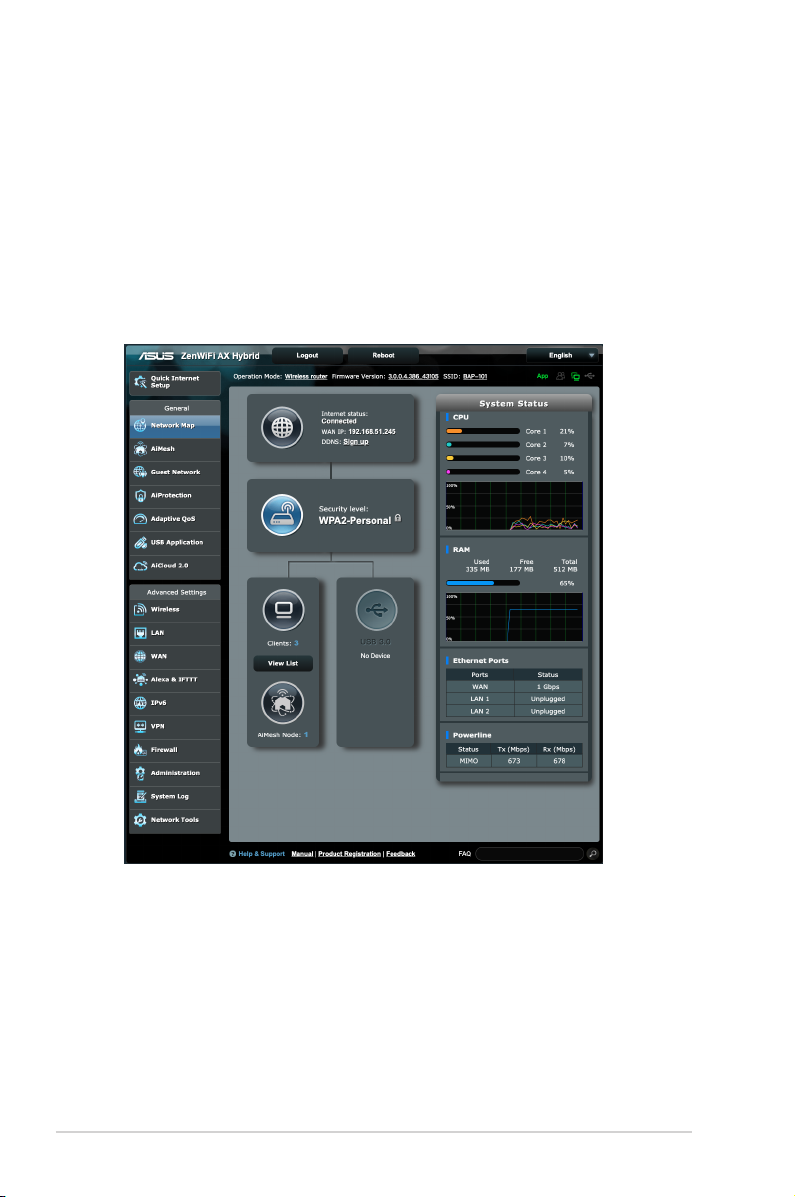
3.1 Using the Network Map
Network Map allows you to congure your network’s security
settings, manage your network clients, and monitor your USB
device.
24
Page 25
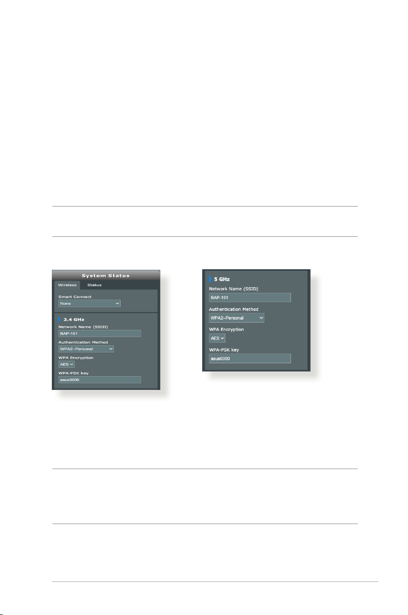
3.1.1 Setting up the wireless security settings
To protect your wireless network from unauthorized access, you
need to congure its security settings.
To set up the wireless security settings:
1. From the navigation panel, go to General > Network Map.
2. On the Network Map screen and under System status, you can
congure the wireless security settings such as SSID, security
level, and encryption settings.
NOTE: You can set up dierent wireless security settings for 2.4GHz and
5GHz bands.
2.4GHz security settings 5GHz security settings
3. On the Wireless name (SSID) eld, key in a unique name for
your wireless network.
4. From the WEP Encryption dropdown list, select the encryption
method for your wireless network.
IMPORTANT! The IEEE 802.11n/ac standard prohibits using High
Throughput with WEP or WPA-TKIP as the unicast cipher. If you use these
encryption methods, your data rate will drop to IEEE 802.11g 54Mbps
connection.
5. Key in your security passkey.
6. Click Apply when done.
25
Page 26
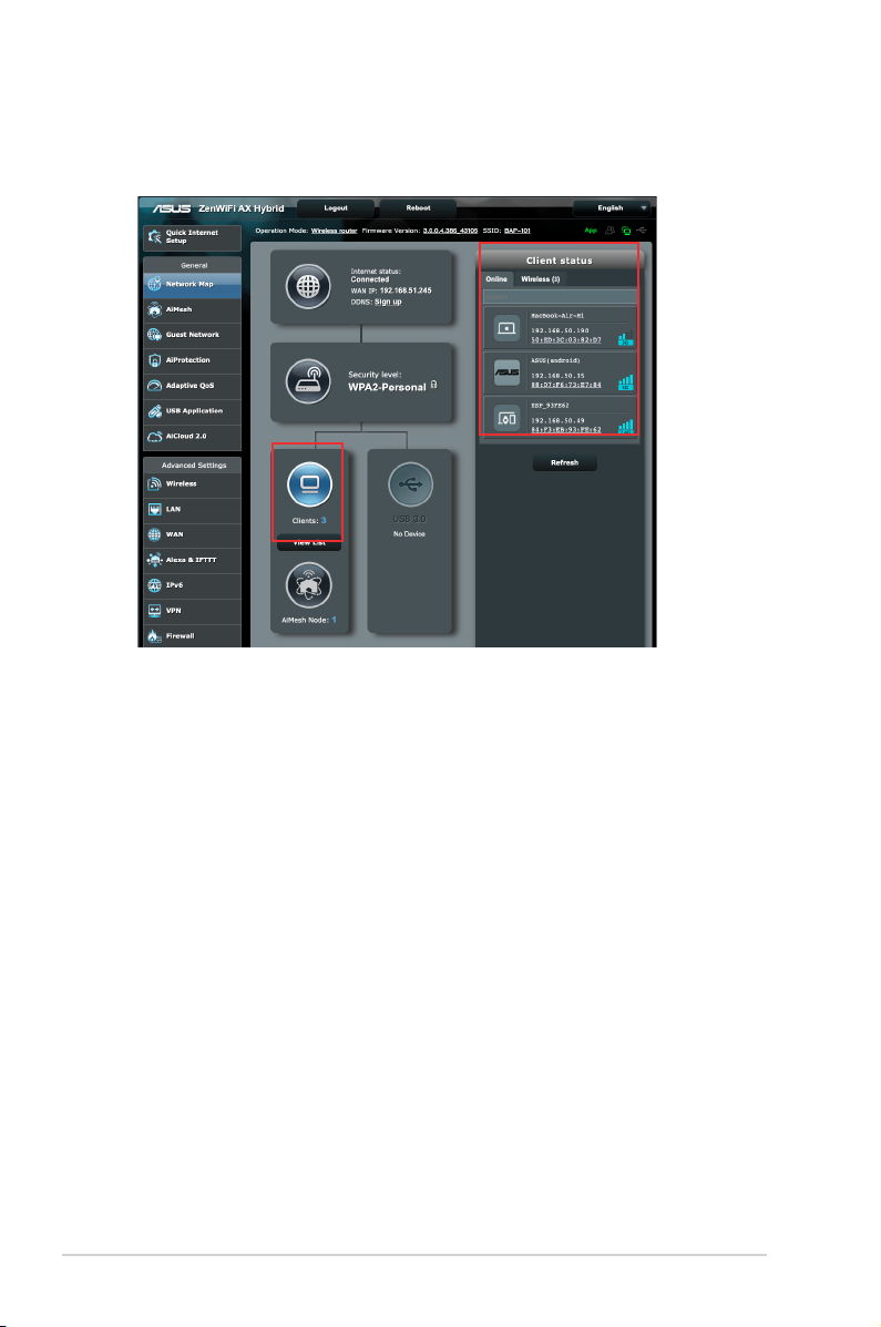
3.1.2 Managing your network clients
To manage your network clients:
1. From the navigation panel, go to General > Network Map tab.
2. On the Network Map screen, select the Client Status icon to
display your network client’s information.
3. To block a client’s access to your network, select the client and
click block.
26
Page 27
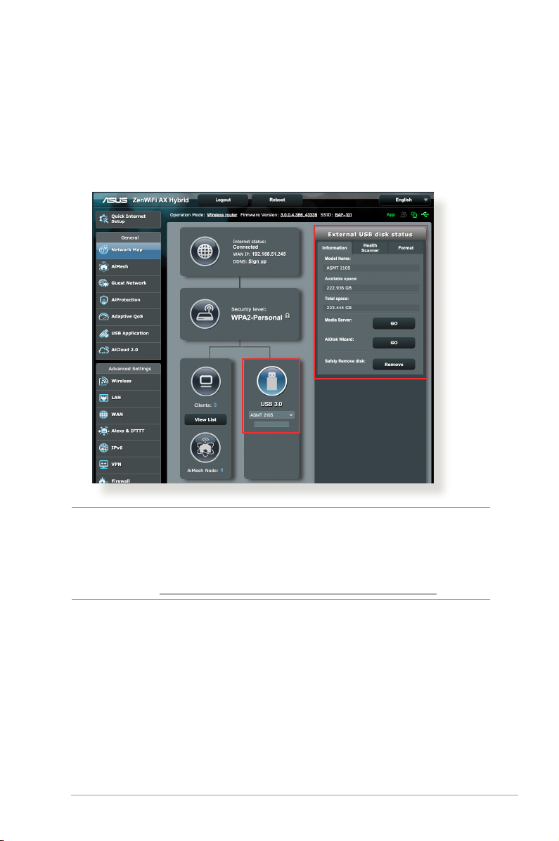
3.1.3 Monitoring your USB device
The ASUS Wireless Router provides a USB port for connecting a
USB device or a USB printer to allow you to share files and printer
with clients in your network.
NOTE: To use this feature, you need to plug a USB storage device,
such as a USB hard disk or a USB ash drive, to the USB 3.0 port on the
rear panel of your wireless router. Ensure that the USB storage device
is formatted and partitioned properly. Refer to the Plug-n-Share Disk
Support List at http://event.asus.com/networks/disksupport.
27
Page 28

IMPORTANT! You rst need to create a share account and its
permission /access rights to allow other network clients to access the
USB device via an FTP site/third-party FTP client utility, Servers Center,
Samba, or AiCloud 2.0. For more details, refer to the section 3.5 Using
the USB Application and 3.6 Using AiCloud 2.0 in this user manual.
To monitor your USB device:
1. From the navigation panel, go to General > Network Map.
2. On the Network Map screen, select the USB Disk Status icon to
display your USB device’s information.
3. On the AiDisk Wizard field, click GO to set up an FTP server for
Internet file sharing.
NOTES:
• For more details, refer to the section 3.5.2 Using Servers Center in
this user manual.
• The wireless router works with most USB HDDs/Flash disks (up to 2TB
size) and supports read-write access for FAT16, FAT32, EXT2, EXT3,
and NTFS.
28
Page 29
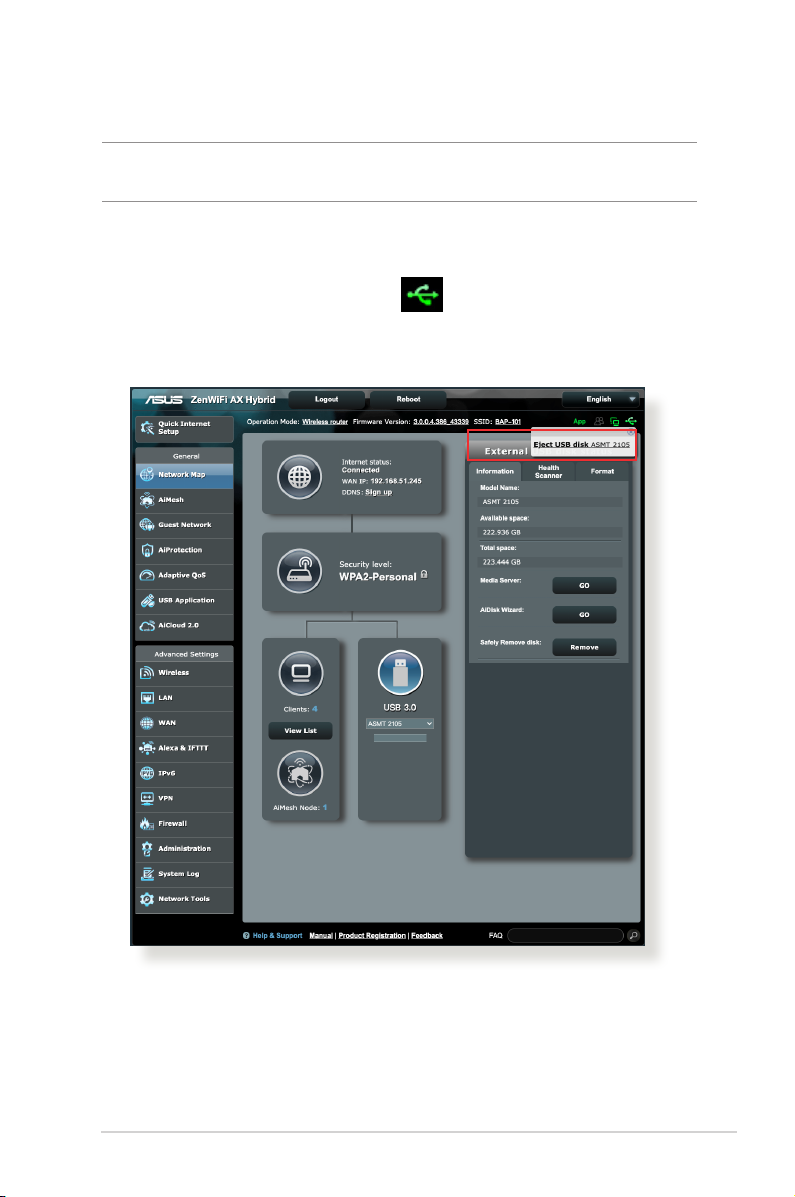
Safely removing the USB disk
IMPORTANT! Incorrect removal of the USB disk may cause data
corruption.
To safely remove the USB disk:
1. From the navigation panel, go to General > Network Map.
2. In the upper right corner, click > Eject USB disk. When
the USB disk is ejected successfully, the USB status shows
Unmounted.
29
Page 30
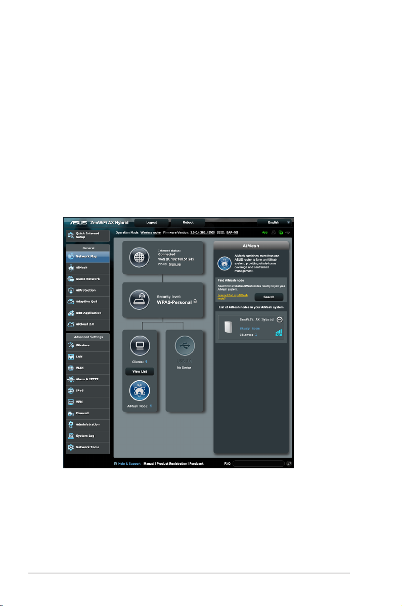
3.1.4 Setting up AiMesh System
To setup ASUS AiMesh, make sure that the AiMesh node stays in
factory defaults. Meanwhile, place the router and node around 3
meters away from each other during setup process.
To set up AiMesh system:
1. Login to your AiMesh router.
2. Go to Network Map page, click the AiMesh Node icon and
then Search for your extending AiMesh node.
3. When the AiMesh node displays on this page, click it to join the
AiMesh system. This will take some time, please wait until the
process of adding the AiMesh node nishes.
30
Page 31
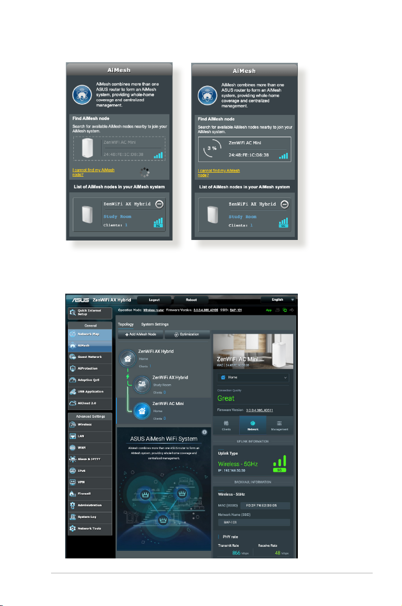
4. When done, go to AiMesh to check the backhaul connection
quality for your AiMesh nodes.
31
Page 32
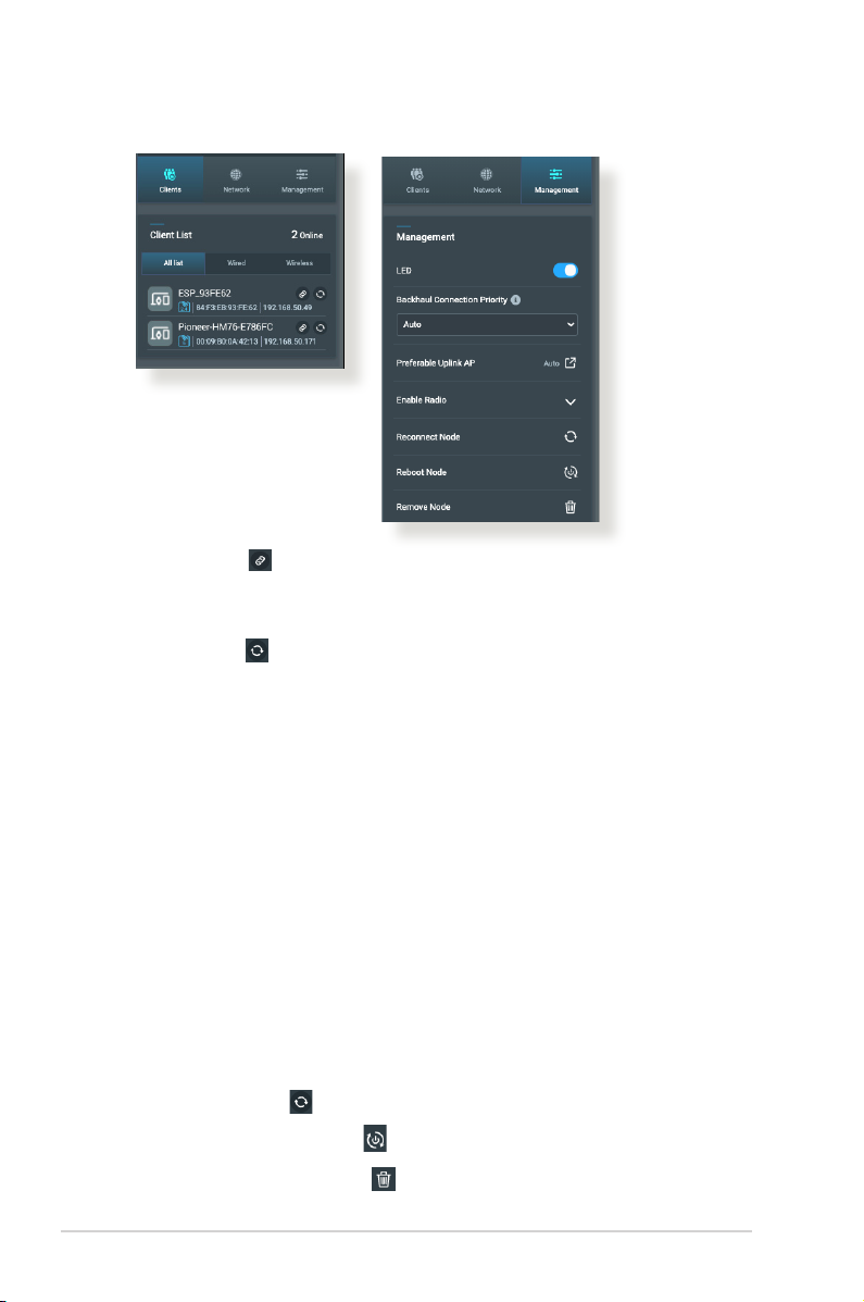
5. You can also nd the information of the connected clients and
tweak backhaul congurations on this page.
Clients
a. Clicking allows you to bind a WiFi client to a specied
AiMesh node.
b. When a client has connected to the nearby AiMesh node,
clicking allows you to reconnect it to the wireless
network again. However, the connection decision rule still
relies on the client driver.
Management
a. Backhaul Connection Priority: If you have preferred
backhaul connection for your AiMesh system, select a rst
specied priority from the dropdown menu on Backhaul
Connection Priority.
b. Preferable Uplink AP: When the node connects to the
parent router or other node via WiFi backhaul, you can
manually select an specied uplink AP from the dropdown
menu.
c. Enable Radio: Enable or disable the node’s radio manually.
d. Reconnect Node: If the backhaul of the node is connected
through WiFi and the operating band is not what you
expect, click to reconnect to an uplink AP.
e. Reboot Node: Click to reboot the node.
f. Remove Node: Click to remove one of the nodes from
your AiMesh system.
32
Page 33
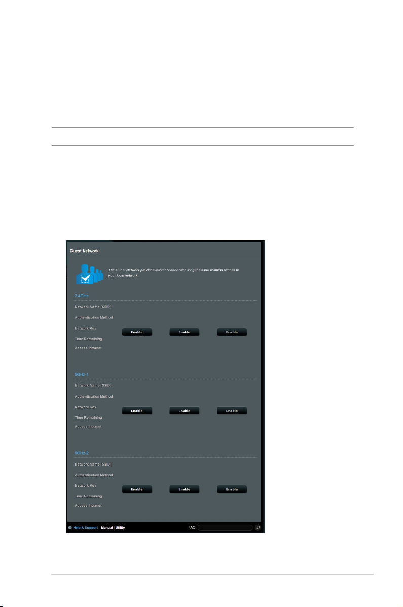
3.2 Creating a Guest Network
The Guest Network provides temporary visitors with Internet
connectivity via access to separate SSIDs or networks without
providing access to your private network.
NOTE: ZenWiFi AX Hybrid supports up to nine SSIDs.
To create a guest network:
1. From the navigation panel, go to General > Guest Network.
2. On the Guest Network screen, select 2.4GHz or 5GHz frequency
band for the guest network that you want to create.
3. Click Enable.
33
Page 34
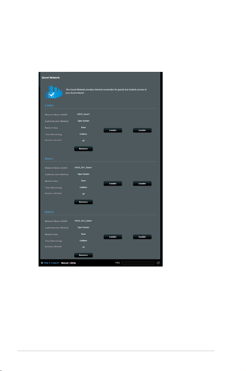
4. To change a guest’s settings, click the guest settings you want
to modify. Click Remove to delete the guest’s settings.
5. Assign a wireless name for your temporary network on the
Network Name (SSID) eld.
6. Select an Authentication Method.
7. If you select a WPA authentication method, select a WPA
Encryption.
8. Specify the Access time or choose Limitless.
9. Select Disable or Enable on the Access Intranet item.
10. When done, click Apply.
34
Page 35
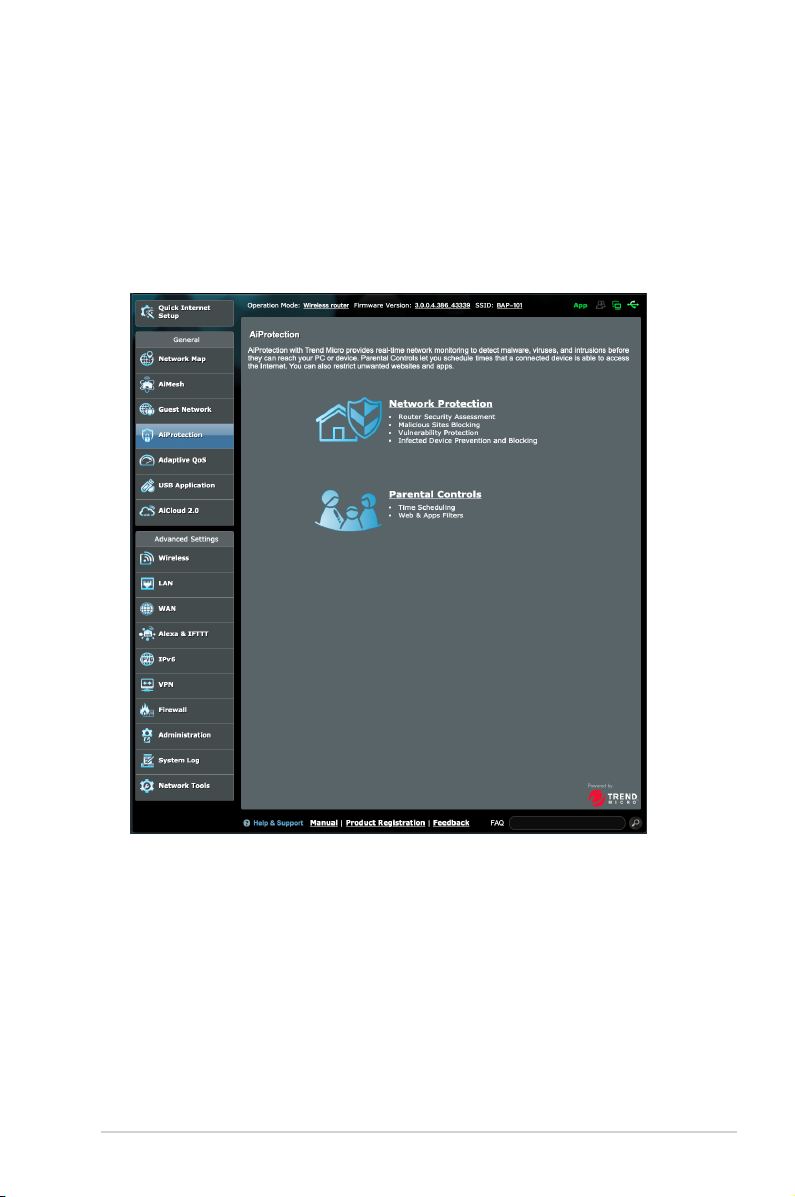
3.3 AiProtection
AiProtection provides real-time monitoring that detects malware,
spyware, and unwanted access. It also lters unwanted websites
and apps and allows you to schedule a time that a connected
device is able to access the Internet.
35
Page 36
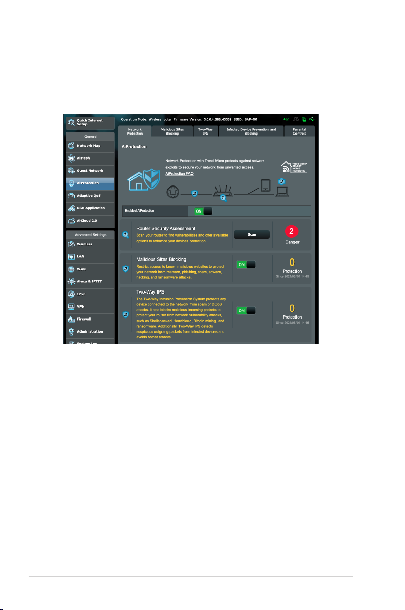
3.3.1 Network Protection
Network Protection prevents network exploits and secures your
network from unwanted access.
Conguring Network Protection
To congure Network Protection:
1. From the navigation panel, go to General > AiProtection.
2. From the AiProtection main page, click on Network
Protection.
3. From the Network Protection tab, click Scan.
When done scanning, the utility displays the results on the
Router Security Assessment page.
36
Page 37
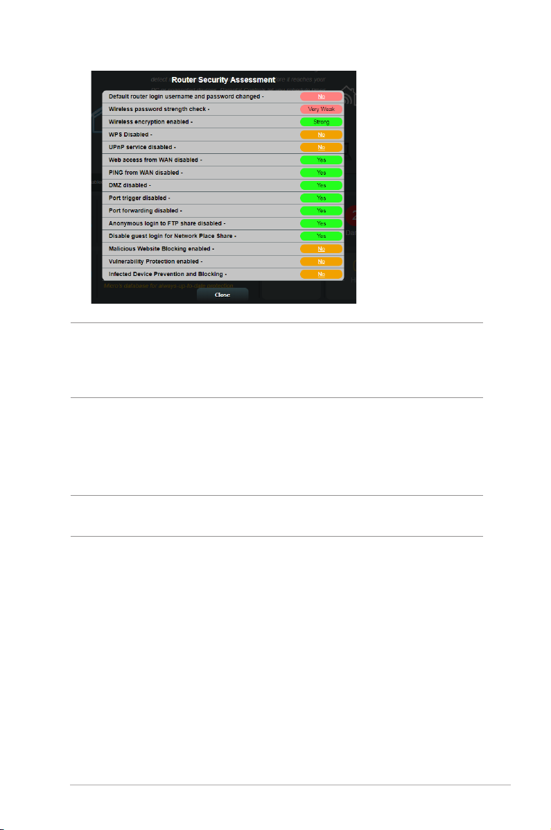
IMPORTANT! Items marked as Yes on the Router Security
Assessment page is considered to be at a safe status. Items marked
as No, Weak, or Very Weak is highly recommended to be congured
accordingly.
4. (Optional) From the Router Security Assessment page,
manually congure the items marked as No, Weak, or Very
Weak. To do this:
a. Click an item.
NOTE: When you click an item, the utility forwards you to the item’s
setting page.
b. From the item’s security settings page, congure and make
the necessary changes and click Apply when done.
c. Go back to the Router Security Assessment page and click
Close to exit the page.
5. To automatically congure the security settings, click Secure
Your Router.
6. When a message prompt appears, click OK.
37
Page 38

Malicious Sites Blocking
This feature restricts access to known malicious websites in the
cloud database for an always-up-to-date protection.
NOTE: This function is automatically enabled if you run the Router
Weakness Scan.
To enable Malicious Sites Blocking:
1. From the navigation panel, go to General > AiProtection.
2. From the AiProtection main page, click on Network
Protection.
3. From the Malicious Sites Blocking pane, click ON.
Two-Way IPS
Two-Way IPS (Intrusion Prevention System) protects your router
from network attacks by both blocking malicious incoming
packets and detecting suspicious outgoing packets.
NOTE: This function is automatically enabled if you run the Router
Weakness Scan.
To enable Two-Way IPS:
1. From the navigation panel, go to General > AiProtection.
2. From the AiProtection main page, click on Network
Protection.
3. From the Two-Way IPS pane, click ON.
38
Page 39

Infected Device Prevention and Blocking
This feature prevents infected devices from communicating
personal information or infected status to external parties.
NOTE: This function is automatically enabled if you run the Router
Weakness Scan.
To enable Infected Device Prevention and Blocking:
1. From the navigation panel, go to General > AiProtection.
2. From the AiProtection main page, click on Network
Protection.
3. From the Infected Device Prevention and Blocking pane,
click ON.
To congure Alert Preference:
1. From the Infected Device Prevention and Blocking pane,
click Alert Preference.
2. Select or key in the e-mail provider, e-mail account, and
password then click Apply.
39
Page 40
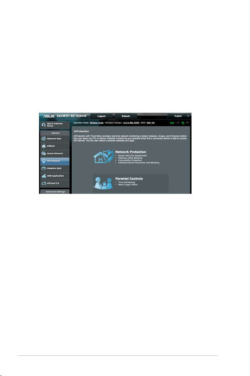
3.3.2 Setting up Parental Controls
Parental Control allows you to control the Internet access time or
set the time limit for a client’s network usage.
To go to the Parental Controls main page:
1. From the navigation panel, go to General > AiProtection.
2. From the AiProtection main page, click on the Parental
Controls tab.
40
Page 41
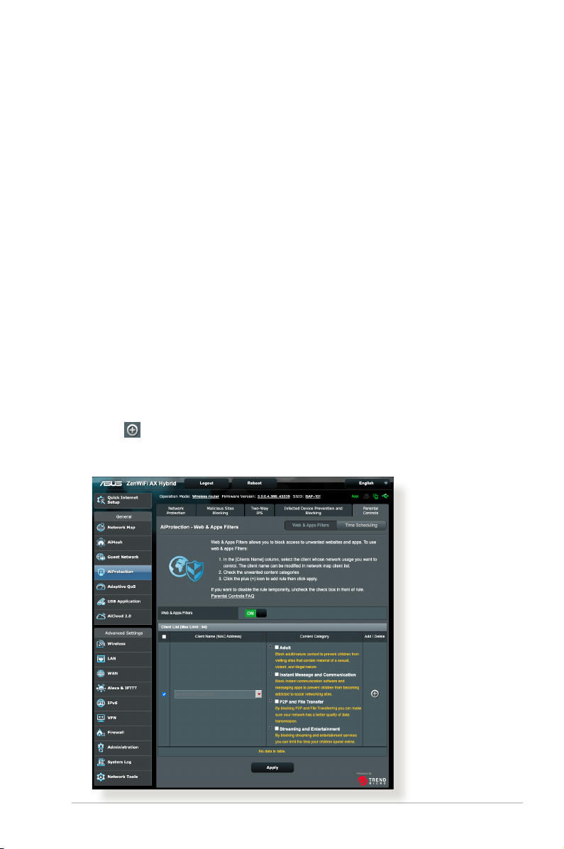
Web & Apps Filters
Web & Apps Filters is a feature of Parental Controls that allows
you to block access to unwanted web sites or applications.
To congure Web & Apps Filters:
1. From the navigation panel, go to General > AiProtection.
2. From the AiProtection main page, click on the Parental
Controls icon to go to the Parental Controls tab.
3. From the Enable Web & Apps Filters pane, click ON.
4. When the End Users License Agreement (EULA) message
prompt appears, click I agree to continue.
5. From the Client List column, select or key in the client’s name
from the drop down list box.
6. From the Content Category column, select the lters from
the four main categories: Adult, Instant Message and
Communication, P2P and File Transfer, and Streaming and
Entertainment.
7. Click to add the client’s prole.
8. Click Apply to save the settings.
41
Page 42
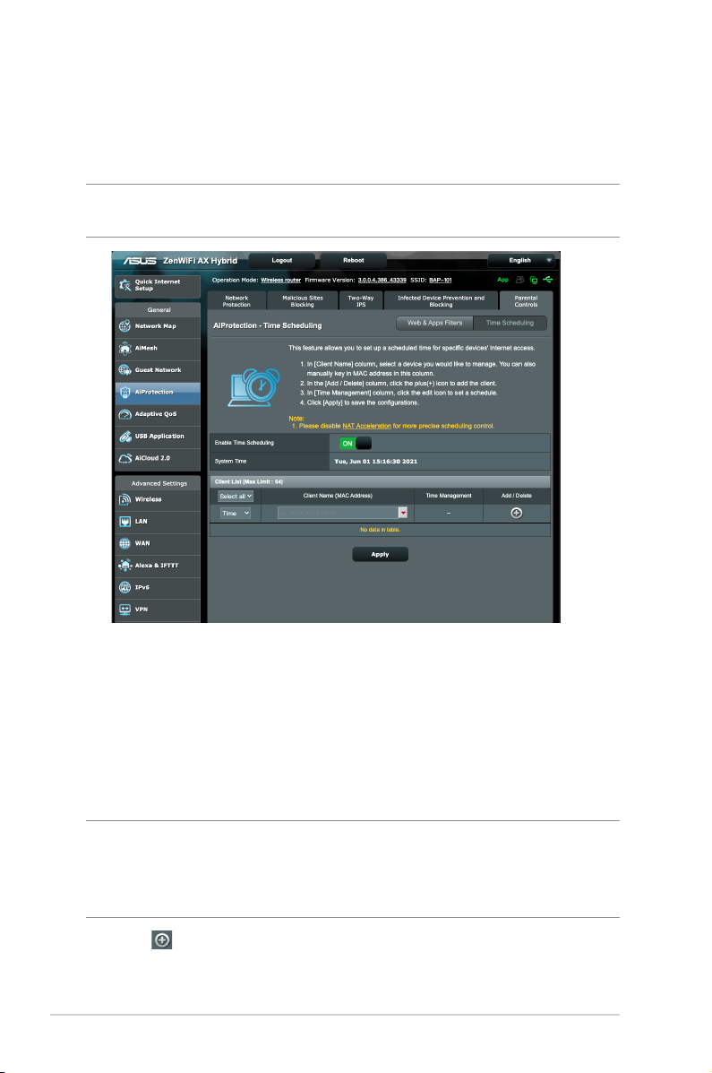
Time Scheduling
Time Scheduling allows you to set the time limit for a client’s
network usage.
NOTE: Ensure that your system time is synchronized with the NTP
server.
To congure Time Scheduling:
1. From the navigation panel, go to General >AiProtection >
Parental Controls > Time Scheduling.
2. From the Enable Time Scheduling pane, click ON.
3. From the Clients Name column, select or key in the client’s
name from the drop down list box.
NOTE: You may also key in the client’s MAC address in the Client
MAC Address column. Ensure that the client name does not contain
special characters or spaces as these may cause the router to function
abnormally.
4. Click to add the client’s prole.
5. Click Apply to save the settings.
42
Page 43
3.4 Using the Trac Manager
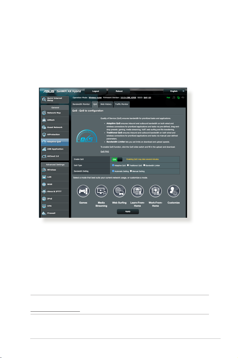
3.4.1 Managing QoS (Quality of Service) Bandwidth
Quality of Service (QoS) allows you to set the bandwidth priority
and manage network trac.
To enable the Adaptive QoS function:
1. From the navigation panel, go to General > Adaptive QoS>
QoS tab.
2. From the Enable QoS pane, click ON.
3. Click Automatic Setting for optimal bandwidth automatically
or Manual Setting to set the upload and download bandwidth
manually.
NOTE: Get the bandwidth information from your ISP. You can also go to
http://speedtest.net to check and get your bandwidth.
43
Page 44

4. Select the QoS Type (Adaptive or Traditional) for your
conguration.
NOTE: The denition of the QoS Type is displayed on the QoS tab for
your reference.
5. Click Apply.
44
Page 45
3.5 Using the USB Application
The USB Applications function provides AiDisk, Servers Center,
Network Printer Server and Download Master submenus.
IMPORTANT! To use the server functions, you need to insert a USB
storage device, such as a USB hard disk or a USB ash drive, in the USB
3.0 port on the rear panel of your wireless router. Ensure that the USB
storage device is formatted and partitioned properly. Refer to the ASUS
website at http://event.asus.com/2009/networks/disksupport/ for the
le system support table.
3.5.1 Using AiDisk
AiDisk allows you to share les stored on a connected USB device
through the Internet. AiDisk also assists you with setting up ASUS
DDNS and an FTP server.
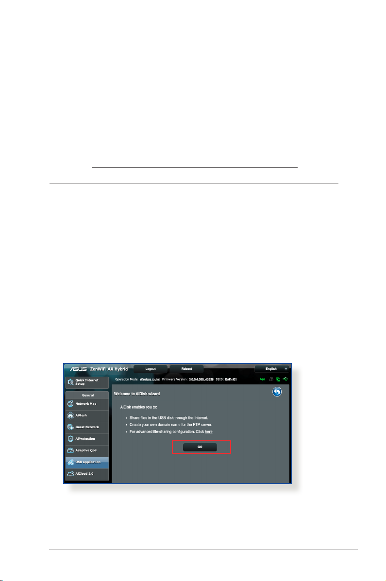
To use AiDisk:
1. From the navigation panel, go to General > USB application,
then click the AiDisk icon.
2. From the Welcome to AiDisk wizard screen, click Go.
45
Page 46
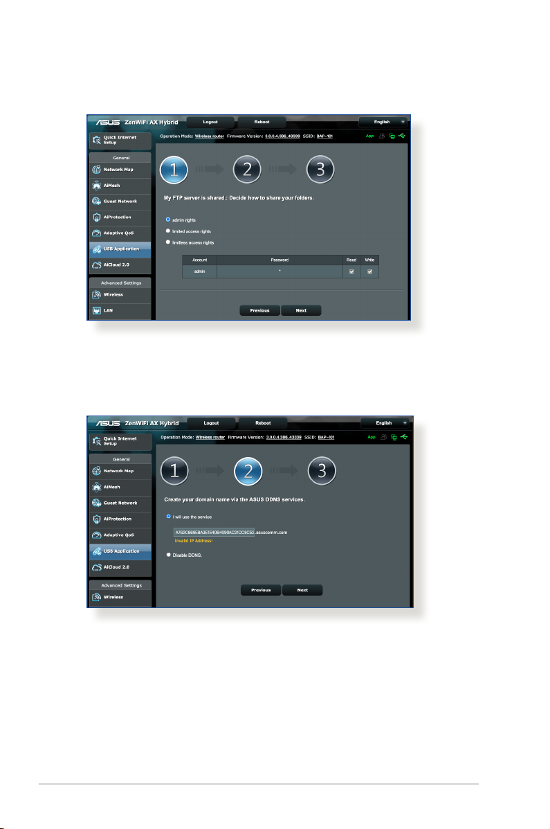
3. Select the access rights that you want to assign to the clients
accessing your shared data.
4. Create your domain name via the ASUS DDNS services, read
the Terms of Service and then select I will use the service and
accept the Terms of service and key in your domain name.
When done, click Next.
You can also select Skip ASUS DDNS settings then click Next
to skip the DDNS setting.
5. Click Finish to complete the setting.
6. To access the FTP site that you created, launch a web browser
or a third-party FTP client utility and key in the ftp link
(ftp://<domain name>.asuscomm.com) you have previously
created.
46
Page 47
3.5.2 Using Servers Center
Servers Center allows you to share the media les from the USB
disk via a Media Server directory, Samba share service, or FTP
share service. You can also congure other settings for the USB
disk in the Servers Center.
Using Media Server
Your wireless router allows DLNA-supported devices to access
multimedia les from the USB disk connected to your wireless
router.
NOTE: Before using the DLNA Media Server function, connect your
device to ZenWiFi AX Hybrid’s network.
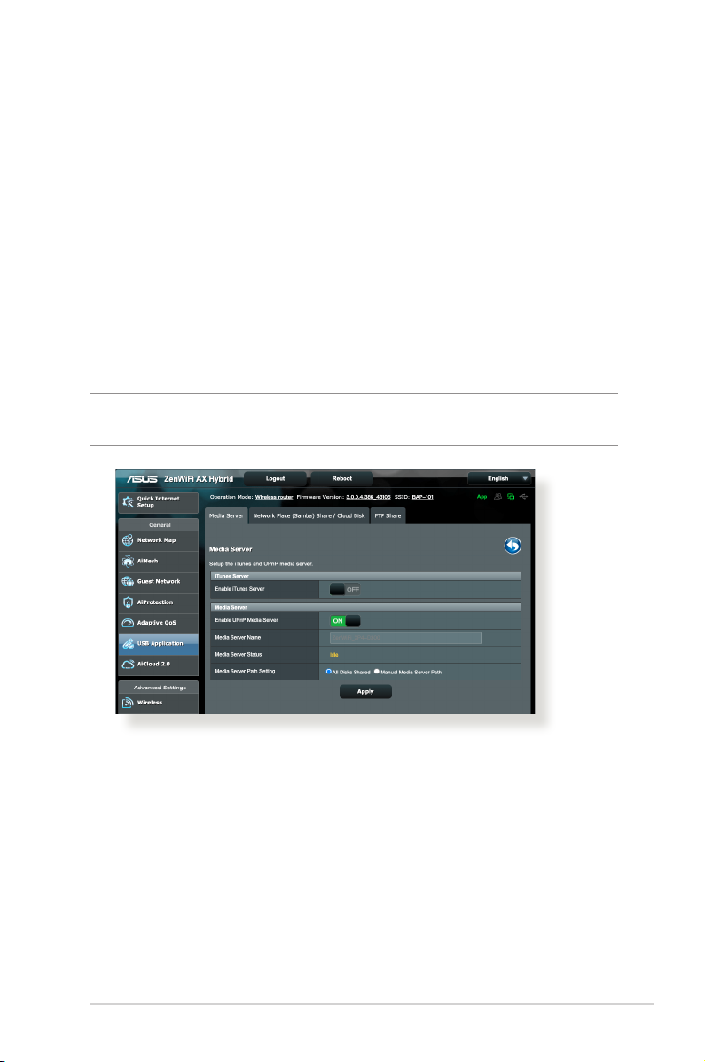
To launch the Media Server setting page, go to General > USB
Application > Media Service tab. Refer to the following for the
descriptions of the elds:
• Enable iTunes Server: Select ON/OFF to enable/disable the
iTunes Server.
• Enable UPnP Server: Select ON/OFF to enable/disable the
UPnP Server.
• Media Server Status: Displays the status of the media server.
• Media Server Path Setting: Select All Disks Shared or
Manual Media Server Path.
47
Page 48
Using Network Place (Samba) Share / Cloud Disk
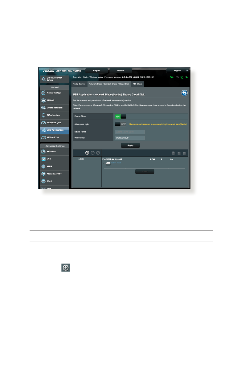
Network Place (Samba) Share / Cloud Disk allows you to set up the
accounts and permissions for the Samba service.
To use Samba share:
1. From the navigation panel, go to General > USB Application >
Network Place (Samba) Share / Cloud Disk tab.
NOTE: Network Place (Samba) Share / Cloud Disk is enabled by default.
2. Follow the steps below to add, delete, or modify an account.
To create a new account:
a) Click to add new account.
b) In the Account and Password elds, key in the name and
password of your network client. Retype the password to
conrm. Click Add to add the account to the list.
48
Page 49
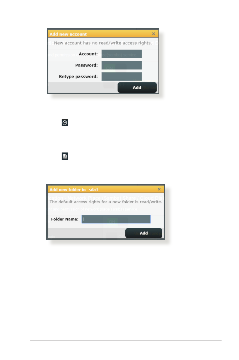
To delete an existing account:
a) Select the account that you want to delete.
b) Click .
c) When prompted, click Delete to conrm the account
deletion.
To add a folder:
a) Click .
b) Enter the folder name, and click Add. The folder that you
created will be added to the folder list.
3. From the list of folders, select the type of access permission
that you want to assign for specic folders:
• R/W: Select this option to assign read/write access.
• R: Select this option to assign read-only access.
• No: Select this option if you do not want to share a specic
le folder.
4. Click Apply to apply the changes.
49
Page 50
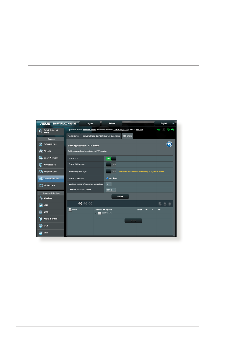
Using the FTP Share service
FTP share enables an FTP server to share les from USB disk to
other devices via your local area network or via the Internet.
IMPORTANT!
• Ensure that you safely remove the USB disk. Incorrect removal of the
USB disk may cause data corruption.
• To safely remove the USB disk, refer to the section Safely removing
the USB disk under 3.1.3 Monitoring your USB device.
50
Page 51

To use FTP Share service:
NOTE: Ensure that you have set up your FTP server through
AiDisk. For more details, refer to the section 3.6.1 Cloud Disk.
1. From the navigation panel, click General > USB Application >
FTP Share tab.
2. From the list of folders, select the type of access rights that you
want to assign for specic folders:
• R/W: Select to assign read/write access for a specic folder.
• W: Select to assign write only access for a specic folder.
• R: Select to assign read only access for a specic folder.
• No: Select this option if you do not want to share a specic
folder.
3. Click Apply to conrm the changes.
4. To access the FTP server, key in the ftp link
ftp://<hostname>.asuscomm.com and your user name and
password on a web browser or a third-party FTP utility.
51
Page 52
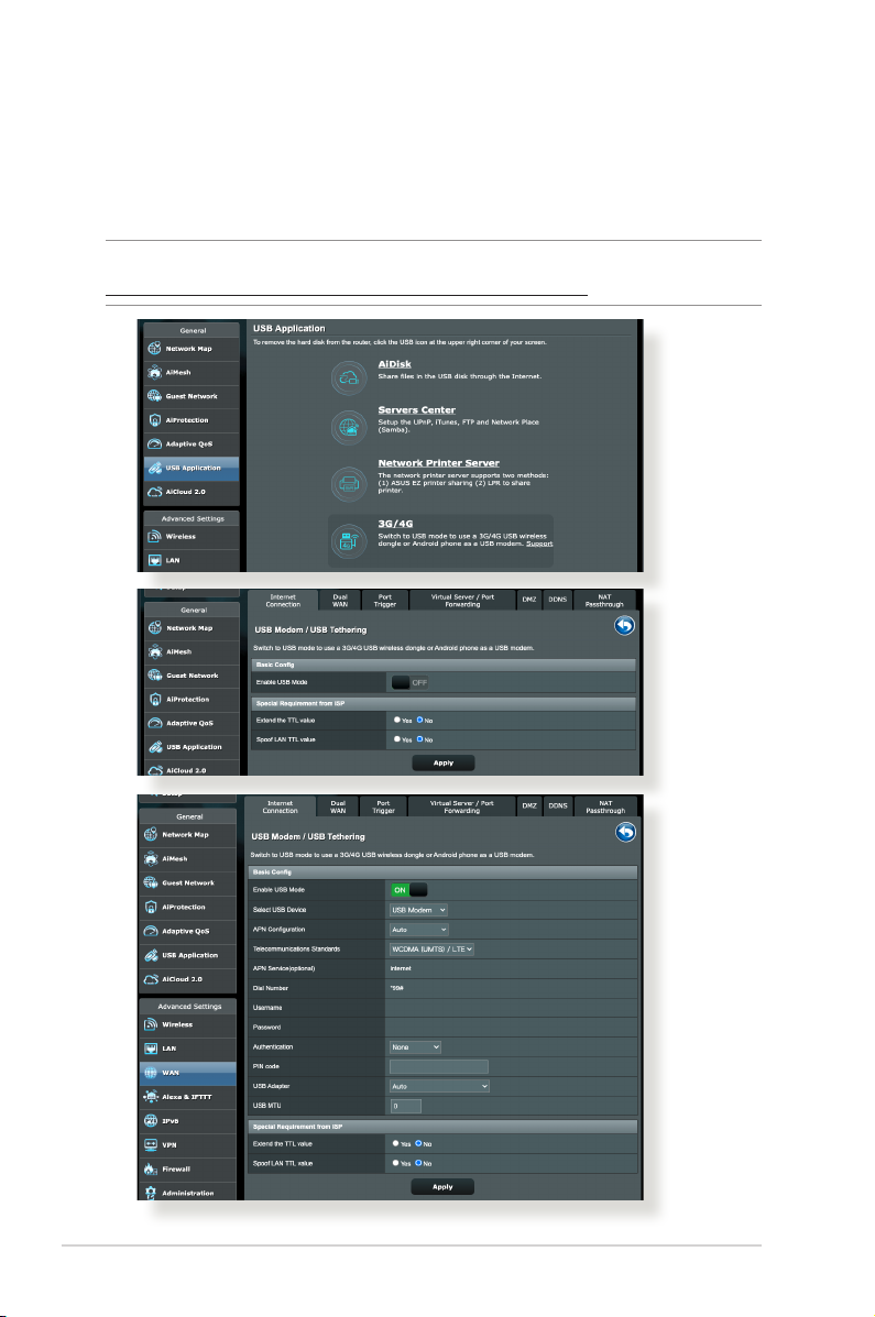
3.5.3 3G/4G
3G/4G USB modems can be connected to ZenWiFi AX Hyrbid to
allow Internet access.
NOTE: For a list of veried USB modems, please visit:
http://event.asus.com/2009/networks/3gsupport/.
52
Page 53
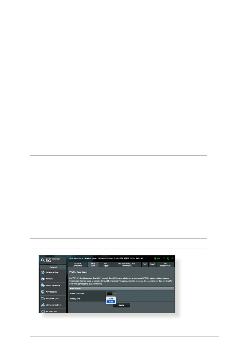
To set up 3G/4G internet access:
1. From the navigation panel, click General > USB Application >
3G/4G.
2. In the Enable USB Mode eld, move the slider to ON.
3. Set up the following:
• Select USB Device: Select your 3G/4G USB device from the
dropdown list.
• APN Conguration: Contact your 3G/4G service provider for
detailed information.
• Telecommunications Standards: Select the
telecommunications standard from the dropdown list.
• Dial Number and PIN code: The 3G/4G provider’s access
number and PIN code for connection.
NOTE: PIN code may vary from dierent providers.
• Username / Password: The username and password will be
provided by the 3G/4G network carrier.
• USB Adapter: Choose your USB 3G / 4G adapter from the
dropdown list. If you are not sure of your USB adapter’s
model or the model is not listed in the options, select Auto.
4. Click Apply.
5. Click Dual WAN tab, select USB as the primary WAN, and click
Apply.
NOTE: The router will reboot for the settings to take eect.
53
Page 54
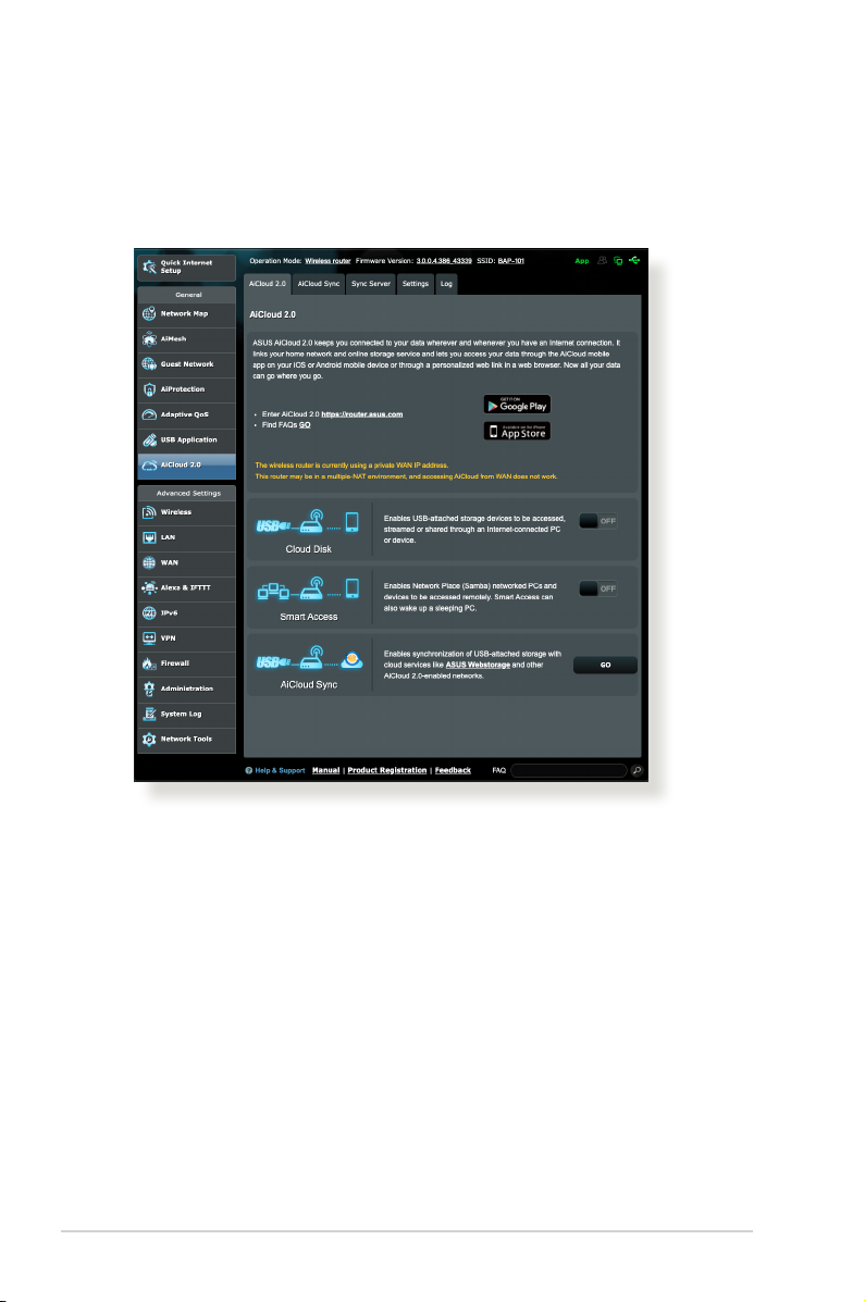
3.6 Using AiCloud 2.0
AiCloud 2.0 is a cloud service application that allows you to save,
sync, share, and access your les.
To use AiCloud 2.0:
1. From Google Play Store or Apple Store, download and install
the ASUS AiCloud 2.0 app to your smart device.
2. Connect your smart device to your network. Follow the
instructions to complete the AiCloud 2.0 setup process.
54
Page 55
3.6.1 Cloud Disk
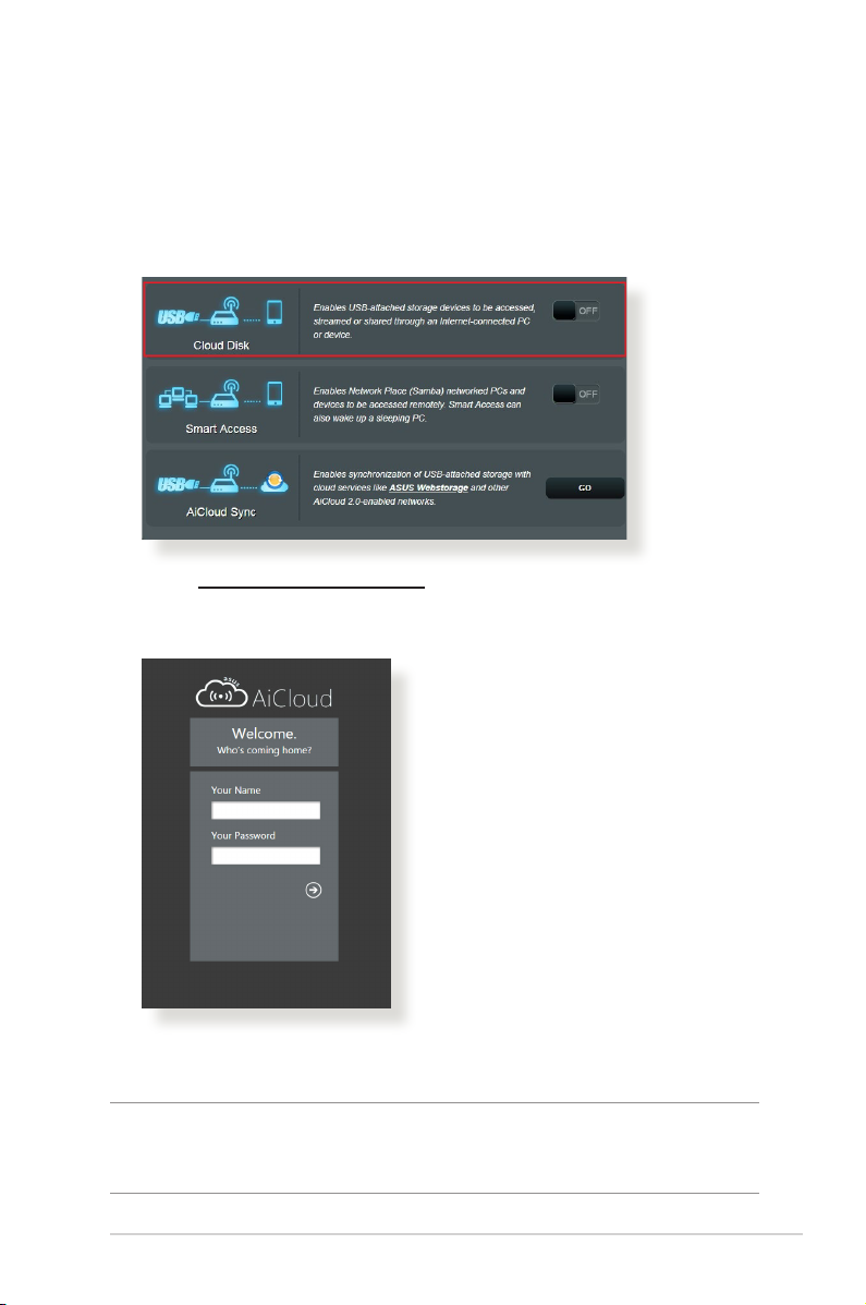
To create a cloud disk:
1. Insert a USB storage device into the wireless router.
2. Turn on Cloud Disk.
3. Go to https://router.asus.com and enter the router login
account and password. For better user experience, we
recommend that you use Google Chrome or Firefox.
4. You can now start accessing Cloud Disk les on devices
connected to the network.
NOTE: When accessing the devices that are connected to the network,
you need to enter the device’s user name and password manually, which
will not be saved by AiCloud 2.0 for security reason.
55
Page 56
3.6.2 Smart Access
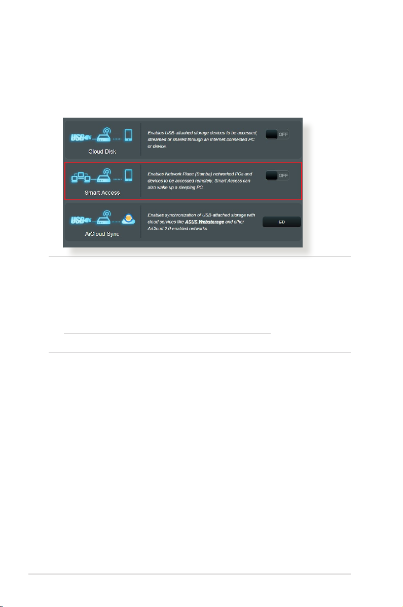
The Smart Access function allows you to easily access your home
network via your router’s domain name.
NOTES:
• You can create a domain name for your router with ASUS DDNS. For
more details, refer to section 4.3.6 DDNS.
• By default, AiCloud 2.0 provides a secure HTTPS connection. Key in
https://[yourASUSDDNSname].asuscomm.com for a very secure
Cloud Disk and Smart Access usage.
56
Page 57
3.6.3 AiCloud Sync
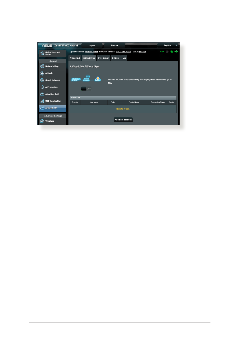
To use AiCloud Sync:
1. Launch AiCloud 2.0, click AiCloud Sync.
2. Select ON to enable AiCloud Sync.
3. Click Add new account.
4. Enter your ASUS WebStorage account password and select the
directory that you want to sync with WebStorage.
5. Click Apply.
57
Page 58
4 Conguring the Advanced 4 Conguring the Advanced
SettingsSettings
4.1 Wireless
4.1.1 General
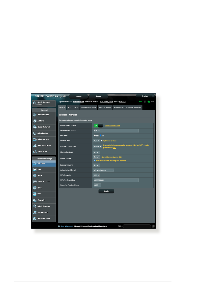
The General tab allows you to congure the basic wireless
settings.
58
Page 59

To congure the basic wireless settings:
1. From the navigation panel, go to Advanced Settings >
Wireless > General tab.
2. At ZenWiFi router, the Smart Connect is enabled by default,
which means 2.4GHz and 5GHz settings will be synchronized.
If you disable Smart Connect, you can select 2.4GHz or 5GHz as
the frequency band for your wireless network.
3. Assign a unique name containing up to 32 characters for your
SSID (Service Set Identier) or network name to identify your
wireless network. Wi-Fi devices can identify and connect to
the wireless network via your assigned SSID. The SSIDs on the
information banner are updated once new SSIDs are saved to
the settings.
NOTE: You can assign unique SSIDs for the 2.4 GHz and 5GHz frequency
bands.
4. In the Hide SSID eld, select Yes to prevent wireless devices
from detecting your SSID. When this function is enabled, you
would need to enter the SSID manually on the wireless device
to access the wireless network.
5. Select any of these wireless mode options to determine the
types of wireless devices that can connect to your wireless
router:
• Auto: Select Auto to allow 802.11AC, 802.11n, 802.11g, and
802.11b devices to connect to the wireless router.
• Legacy: Select Legacy to allow 802.11b/g/n devices to
connect to the wireless router. Hardware that supports
802.11n natively, however, will only run at a maximum speed
of 54Mbps.
• N only: Select N only to maximize wireless N performance.
This setting prevents 802.11g and 802.11b devices from
connecting to the wireless router.
59
Page 60

6. Select any of these channel bandwidth to accommodate higher
transmission speeds:
40MHz/80MHz: Select this bandwidth to maximize the
wireless throughput.
20MHz (default): Select this bandwidth if you encounter some
issues with your wireless connection.
7. Select the operating channel for your wireless router. Select
Auto to allow the wireless router to automatically select the
channel that has the least amount of interference.
8. Select any of these authentication methods:
• Open System: This option provides no security.
• Shared Key: You must use WEP encryption and enter at least
one shared key.
• WPA/WPA2/WPA3 Personal/WPA Auto-Personal: This
option provides strong security. You can use either WPA (with
TKIP) or WPA2 (with AES). If you select this option, you must
use TKIP + AES encryption and enter the WPA passphrase
(network key).
• WPA/WPA2 Enterprise/WPA Auto-Enterprise: This option
provides very strong security. It is with integrated EAP server
or an external RADIUS back-end authentication server.
• Radius with 802.1x
NOTE: Your wireless router supports the maximum transmission rate
of 54Mbps when the Wireless Mode is set to Auto and encryption
method is WEP or TKIP.
9. Select any of these WEP (Wired Equivalent Privacy) Encryption
options for the data transmitted over your wireless network:
• O: Disables WEP encryption
• 64-bit: Enables weak WEP encryption
• 128-bit: Enables improved WEP encryption
10.When done, click Apply.
60
Page 61
4.1.2 WPS
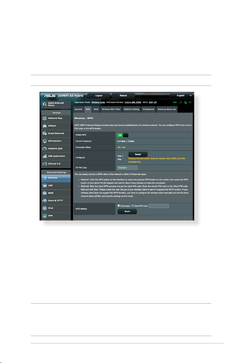
WPS (Wi-Fi Protected Setup) is a wireless security standard that
allows you to easily connect devices to a wireless network. You
can congure the WPS function via the PIN code or WPS button.
NOTE: Ensure that the devices support WPS.
To enable WPS on your wireless network:
1. From the navigation panel, go to Advanced Settings >
Wireless > WPS tab.
2. In the Enable WPS eld, move the slider to ON.
3. WPS uses 2.4GHz and 5GHz concurrently by default. If you want
to change the frequency to 2.4GHz or 5GHz, turn OFF the WPS
function, click Switch Frequency in the Current Frequency
eld, and turn WPS ON again.
NOTE: WPS supports authentication using Open System, WPA-Personal,
WPA2-Personal and WPA3-Personal. WPS does not support a wireless
network that uses a Shared Key, WPA-Enterprise, WPA2-Enterprise, and
RADIUS encryption method.
61
Page 62
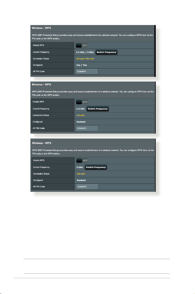
4. In the WPS Method eld, select Push Button or Client PIN
code. If you select Push button, go to step 5. If you select
Client PIN Code, go to step 6.
5. To set up WPS using the router’s WPS button, follow these
steps:
a. Click Start or press the WPS button found at the front of the
wireless router.
b. Press the WPS button on your wireless device. This is
normally identied by the WPS logo.
NOTE: Check your wireless device or its user manual for the location of
the WPS button.
62
Page 63

c. The wireless router will scan for any available WPS devices.
If the wireless router does not nd any WPS devices, it will
switch to standby mode.
6. To set up WPS using the Client’s PIN code, follow these steps:
a. Locate the WPS PIN code on your wireless device’s user
manual or on the device itself.
b. Key in the Client PIN code on the text box.
c. Click Start to put your wireless router into WPS survey mode.
The router’s LED indicators quickly ash three times until the
WPS setup is completed.
63
Page 64
4.1.3 Bridge
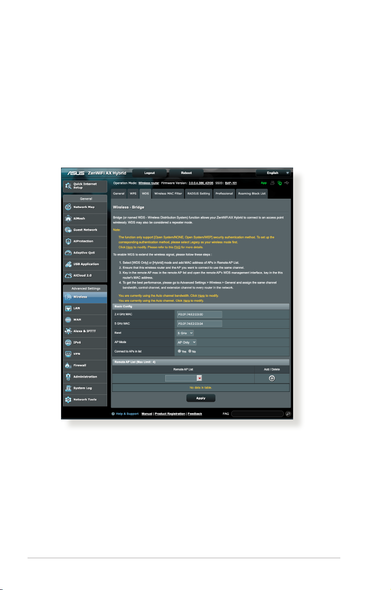
Bridge or WDS (Wireless Distribution System) allows your ASUS
wireless router to connect to another wireless access point
exclusively, preventing other wireless devices or stations to access
your ASUS wireless router. It can also be considered as a wireless
repeater where your ASUS wireless router communicates with
another access point and other wireless devices.
To set up the wireless bridge:
1. From the navigation panel, go to Advanced Settings >
Wireless > WDS tab.
2. Select the frequency band for the wireless bridge.
3. In the AP Mode eld, select any of these options:
• AP Only: Disables the Wireless Bridge function.
64
Page 65
• WDS Only: Enables the Wireless Bridge feature but prevents
other wireless devices/stations from connecting to the
router.
• HYBRID: Enables the Wireless Bridge feature and allows
other wireless devices/stations to connect to the router.
NOTE: In Hybrid mode, wireless devices connected to the ASUS wireless
router will only receive half the connection speed of the Access Point.
4. In the Connect to APs in list eld, click Yes if you want to
connect to an Access Point listed in the Remote AP List.
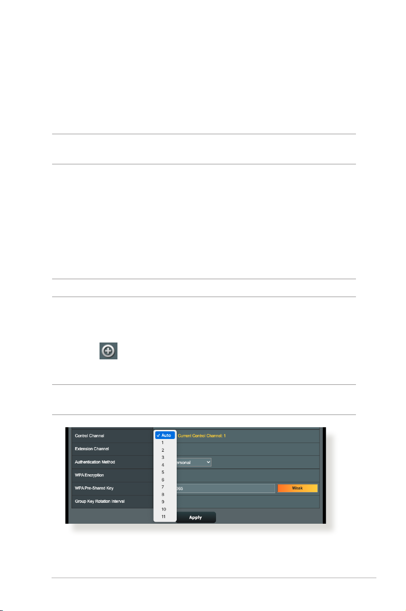
5. In the Control Channel eld, select the operating channel
for the wireless bridge. Select Auto to allow the router to
automatically select the channel with the least amount of
interference.
NOTE: Channel availability varies per country or region.
6. On the Remote AP List, key in a MAC address and click the Add
button to enter the MAC address of other available Access
Points.
NOTE: Any Access Point added to the list should be on the same Control
Channel as the ASUS wireless router.
7. Click Apply.
65
Page 66
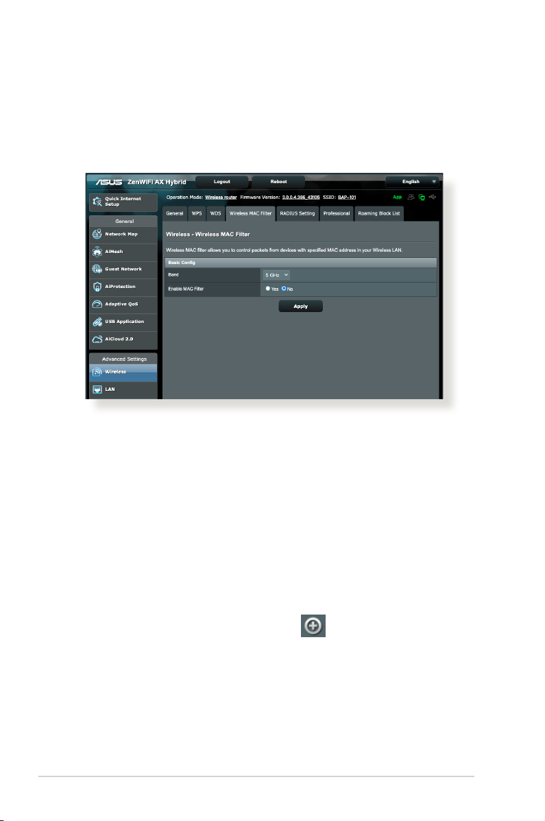
4.1.4 Wireless MAC Filter
Wireless MAC lter provides control over packets transmitted to
a specied MAC (Media Access Control) address on your wireless
network.
To set up the Wireless MAC lter:
1. From the navigation panel, go to Advanced Settings >
Wireless > Wireless MAC Filter tab.
2. Tick Ye s in the Enable Mac Filter eld.
3. In the MAC Filter Mode dropdown list, select either Accept or
Reject.
• Select Accept to allow devices in the MAC lter list to access
to the wireless network.
• Select Reject to prevent devices in the MAC lter list to
access to the wireless network.
4. On the MAC lter list, click the Add button and key in the
MAC address of the wireless device.
5. Click Apply.
66
Page 67
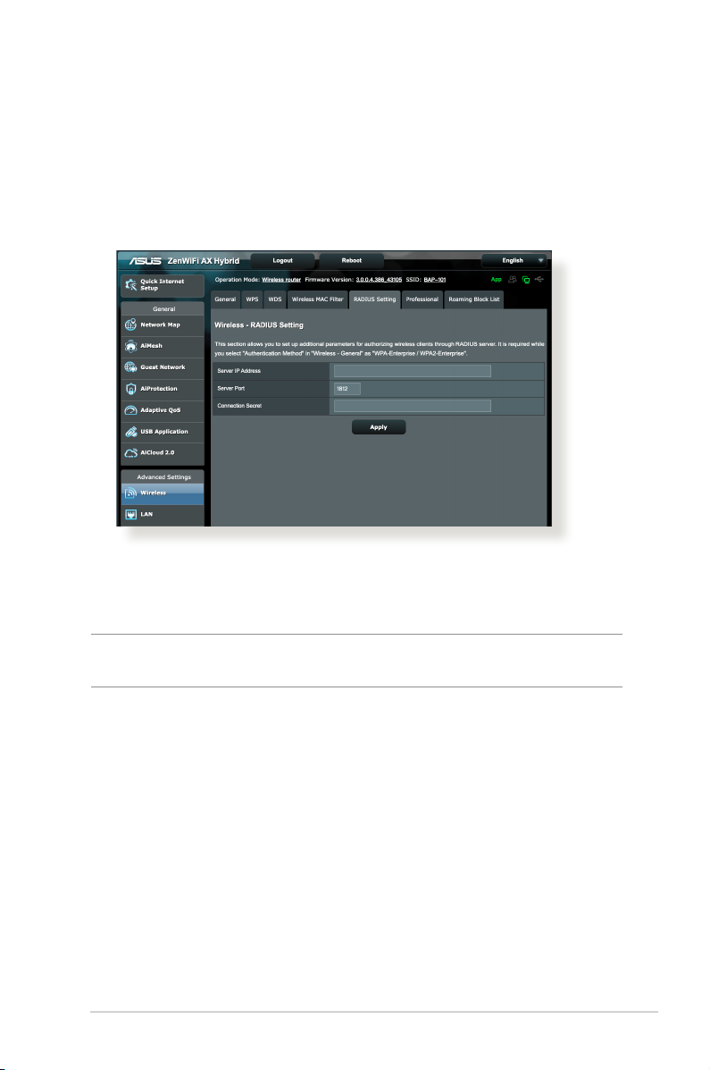
4.1.5 RADIUS Setting
RADIUS (Remote Authentication Dial In User Service) Setting
provides an extra layer of security when you choose WPAEnterprise, WPA2-Enterprise, or Radius with 802.1x as your
Authentication Mode.
To set up wireless RADIUS settings:
1. Ensure that the wireless router’s authentication mode is set to
WPA-Enterprise, WPA2-Enterprise, or Radius with 802.1x.
NOTE: Please refer to section 4.1.1 General section for conguring your
wireless router’s Authentication Mode.
2. From the navigation panel, go to Advanced Settings >
Wireless > RADIUS Setting.
3. Select a frequency band if Smart Connect is disabled.
67
Page 68
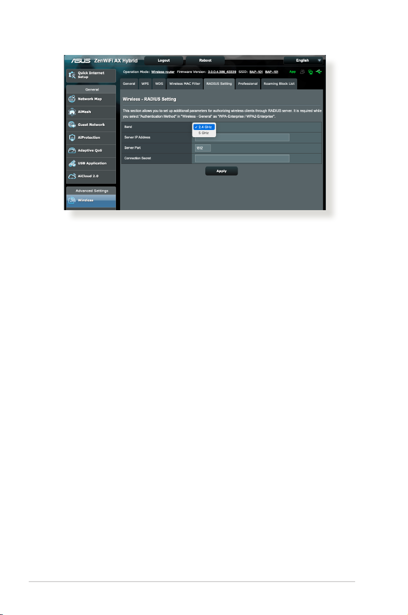
4. In the Server IP Address eld, key in your RADIUS server’s IP
Address.
5. In the Connection Secret eld, assign the password to access
your RADIUS server.
6. Click Apply.
68
Page 69
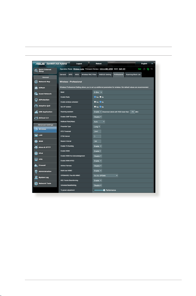
4.1.6 Professional
The Professional screen provides advanced conguration options.
NOTE: We recommend that you use the default values on this page.
In the Professional screen, you can congure the following:
• Band: Select the frequency band that the professional
settings will be applied to.
• Enable Radio: Select Ye s to enable wireless networking.
Select No to disable wireless networking.
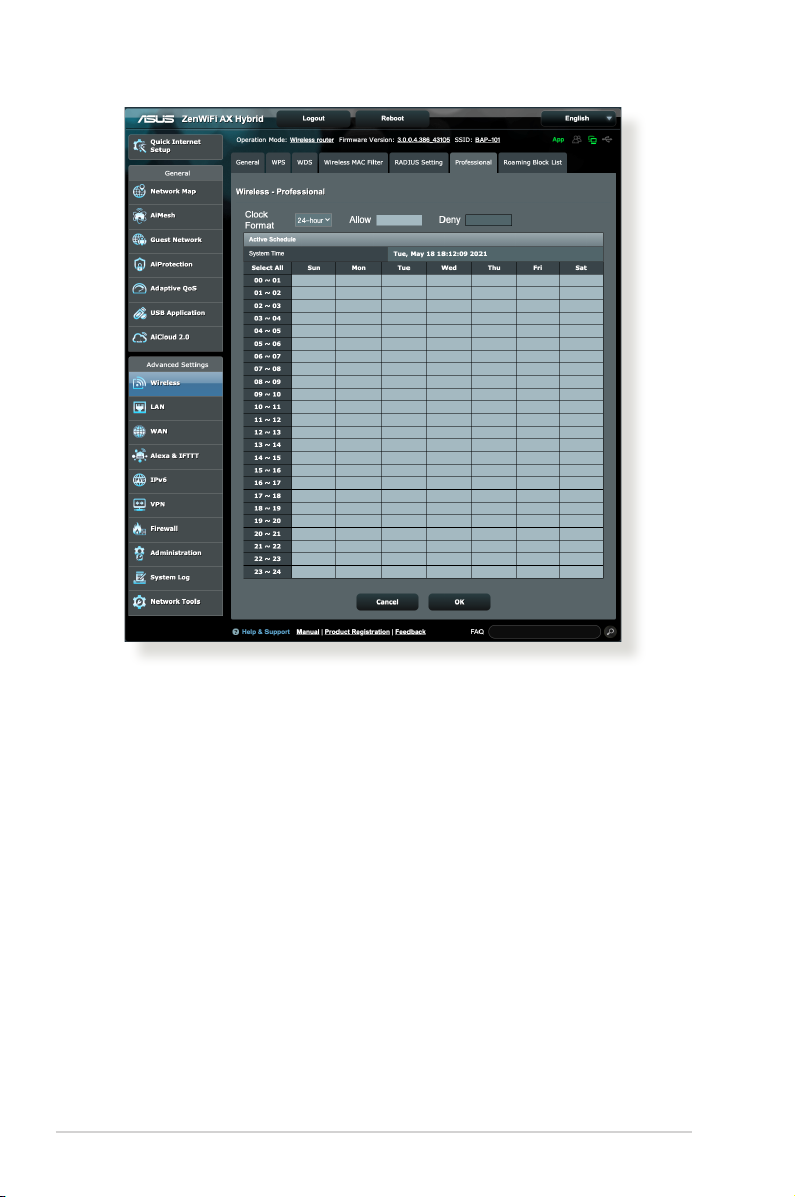
• Enable wireless scheduler: You can choose clock format as
24-hour or 12-hour. The color in the table indicates Allow or
Deny. Click each frame to change the settings of the hour of
the weekdays and click OK when done.
69
Page 70
70
• Set AP isolated: The Set AP isolated item prevents wireless
devices on your network from communicating with each
other. This feature is useful if many guests frequently join or
leave your network. Select Yes to enable this feature or select
No to disable.
• Multicast rate (Mbps): Select the multicast transmission
rate or click Disable to switch o simultaneous single
transmission.
• Preamble Type: Preamble Type denes the length of time
that the router spent for CRC (Cyclic Redundancy Check). CRC
is a method of detecting errors during data transmission.
Select Short for a busy wireless network with high network
trac. Select Long if your wireless network is composed of
older or legacy wireless devices.
• RTS Threshold: Select a lower value for RTS (Request to
Send) Threshold to improve wireless communication in a
busy or noisy wireless network with high network trac and
numerous wireless devices.
Page 71

• DTIM Interval: DTIM (Delivery Trac Indication Message)
Interval or Data Beacon Rate is the time interval before a
signal is sent to a wireless device in sleep mode indicating
that a data packet is awaiting delivery. The default value is
three milliseconds.
• Beacon Interval: Beacon Interval is the time between one
DTIM and the next. The default value is 100 milliseconds.
Lower the Beacon Interval value for an unstable wireless
connection or for roaming devices.
• Enable TX Bursting: Enable TX Bursting improves
transmission speed between the wireless router and 802.11g
devices.
• Enable WMM APSD: Enable WMM APSD (Wi-Fi Multimedia
Automatic Power Save Delivery) to improve power
management between wireless devices. Select Disable to
switch o WMM APSD.
71
Page 72
4.2 LAN
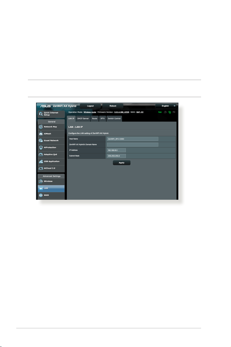
4.2.1 LAN IP
The LAN IP screen allows you to modify the LAN IP settings of your
wireless router.
NOTE: Any changes to the LAN IP address will be reected on your
DHCP settings.
To modify the LAN IP settings:
1. From the navigation panel, go to Advanced Settings > LAN >
LAN IP tab.
2. Modify the IP address and Subnet Mask.
3. When done, click Apply.
72
Page 73
4.2.2 DHCP Server
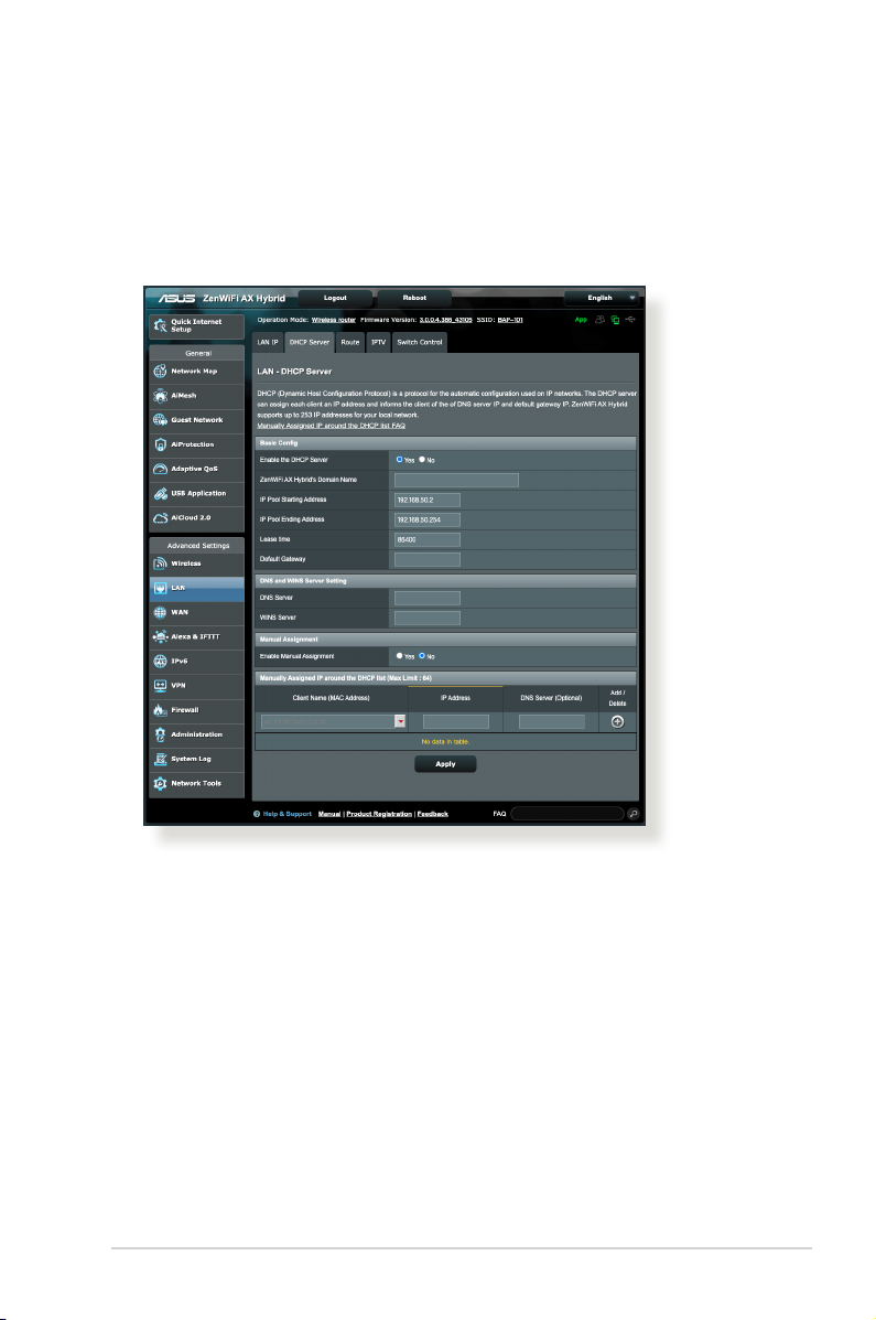
Your wireless router uses DHCP to assign IP addresses
automatically on your network. You can specify the IP address
range and lease time for the clients on your network.
To congure the DHCP server:
1. From the navigation panel, go to Advanced Settings > LAN >
DHCP Server tab.
2. In the Enable the DHCP Server eld, tick Yes .
3. In the ZenWiFi AX Hybrid’s Domain Name text box, enter a
domain name for the wireless router.
4. In the IP Pool Starting Address eld, key in the starting IP
address.
5. In the IP Pool Ending Address eld, key in the ending IP
address.
73
Page 74

6. In the Lease time eld, specify in seconds when an assigned
IP address will expire. Once it reaches this time limit, the DHCP
server will then assign a new IP address.
NOTES:
• We recommend that you use an IP address format of 192.168.1.xxx
(where xxx can be any number between 2 and 254) when specifying
an IP address range.
• An IP Pool Starting Address should not be greater than the IP Pool
Ending Address.
7. In the DNS Server and WINS Server eld, key in your DNS
Server and WINS Server IP address if needed.
8. Your wireless router can also manually assign IP addresses to
devices on the network. On the Enable Manual Assignment
eld, choose Yes to assign an IP address to specic MAC
addresses on the network. Up to 32 MAC Addresses can be
added to the DHCP list for manual assignment.
74
Page 75
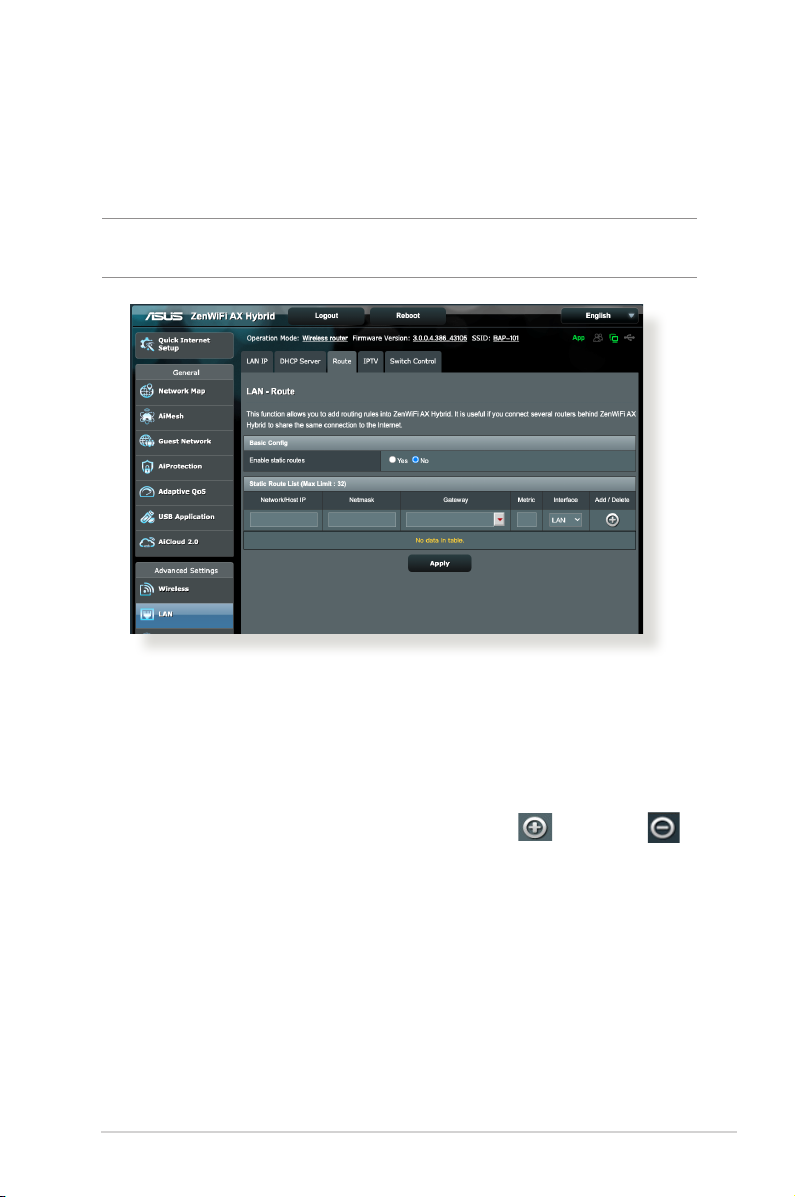
4.2.3 Route
If your network makes use of more than one wireless router, you
can congure a routing table to share the same Internet service.
NOTE: We recommend that you do not change the default route
settings unless you have advanced knowledge of routing tables.
To congure the LAN Routing table:
1. From the navigation panel, go to Advanced Settings > LAN >
Route tab.
2. On the Enable static routes eld, choose Yes.
3. On the Static Route List, enter the network information of
other access points or nodes. Click the Add or Delete
button to add or remove a device on the list.
4. Click Apply.
75
Page 76
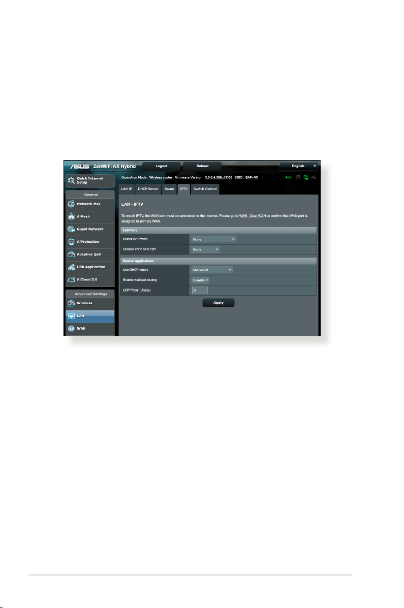
4.2.4 IPTV
The wireless router supports connection to IPTV services through
an ISP or a LAN. The IPTV tab provides the conguration settings
needed to set up IPTV, VoIP, multicasting, and UDP for your
service. Contact your ISP for specic information regarding your
service.
76
Page 77
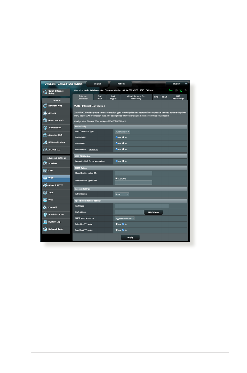
4.3 WAN
4.3.1 Internet Connection
The Internet Connection screen allows you to congure the
settings of various WAN connection types.
To congure the WAN connection settings:
1. From the navigation panel, go to Advanced Settings > WAN >
Internet Connection tab.
2. Congure the following settings below. When done, click
Apply.
• WAN Connection Type: Choose your Internet Service
Provider type. The choices are Automatic IP, PPPoE, PPTP,
L2TP or xed IP. Consult your ISP if the router is unable
to obtain a valid IP address or if you are unsure the WAN
connection type.
77
Page 78

• Enable WAN: Select Ye s to allow the router Internet access.
Select No to disable Internet access.
• Enable NAT: NAT (Network Address Translation) is a system
where one public IP (WAN IP) is used to provide Internet
access to network clients with a private IP address in a LAN.
The private IP address of each network client is saved in a NAT
table and is used to route incoming data packets.
• Enable UPnP: UPnP (Universal Plug and Play) allows several
devices (such as routers, televisions, stereo systems, game
consoles, and cellular phone), to be controlled via an IP-based
network with or without a central control through a gateway.
UPnP connects PCs of all form factors, providing a seamless
network for remote conguration and data transfer. Using
UPnP, a new network device is discovered automatically.
Once connected to the network, devices can be remotely
congured to support P2P applications, interactive gaming,
video conferencing, and web or proxy servers. Unlike Port
forwarding, which involves manually conguring port
settings, UPnP automatically congures the router to accept
incoming connections and direct requests to a specic PC on
the local network.
• Connect to DNS Server automatically: Allows this router to
get the DNS IP address from the ISP automatically. A DNS is a
host on the Internet that translates Internet names to numeric
IP addresses.
• Authentication: This item may be specied by some ISPs.
Check with your ISP and ll them in if required.
• Host Name: This eld allows you to provide a host name for
your router. It is usually a special requirement from your ISP.
If your ISP assigned a host name to your computer, enter the
host name here.
• MAC Address: MAC (Media Access Control) address is a
unique identier for your networking device. Some ISPs
78
Page 79

monitor the MAC address of networking devices that connect
to their service and reject any unrecognized device that
attempt to connect. To avoid connection issues due to an
unregistered MAC address, you can:
• Contact your ISP and update the MAC address associated
with your ISP service.
• Clone or change the MAC address of the ASUS wireless router
to match the MAC address of the previous networking device
recognized by the ISP.
4.3.2 Dual WAN
Your ASUS wireless router provides dual WAN support. You can set
the dual WAN feature to any of these two modes:
• Fail Over: Select this mode to use the secondary WAN as the
backup network access.
• Load Balance: Select this mode to allow concurrent use
of dual WAN connections for improved bandwidth and
reliability.
• Allow failback: Tick the checkbox to allow Internet
connection switch back to primary WAN automatically when
primary WAN becomes available.
79
Page 80
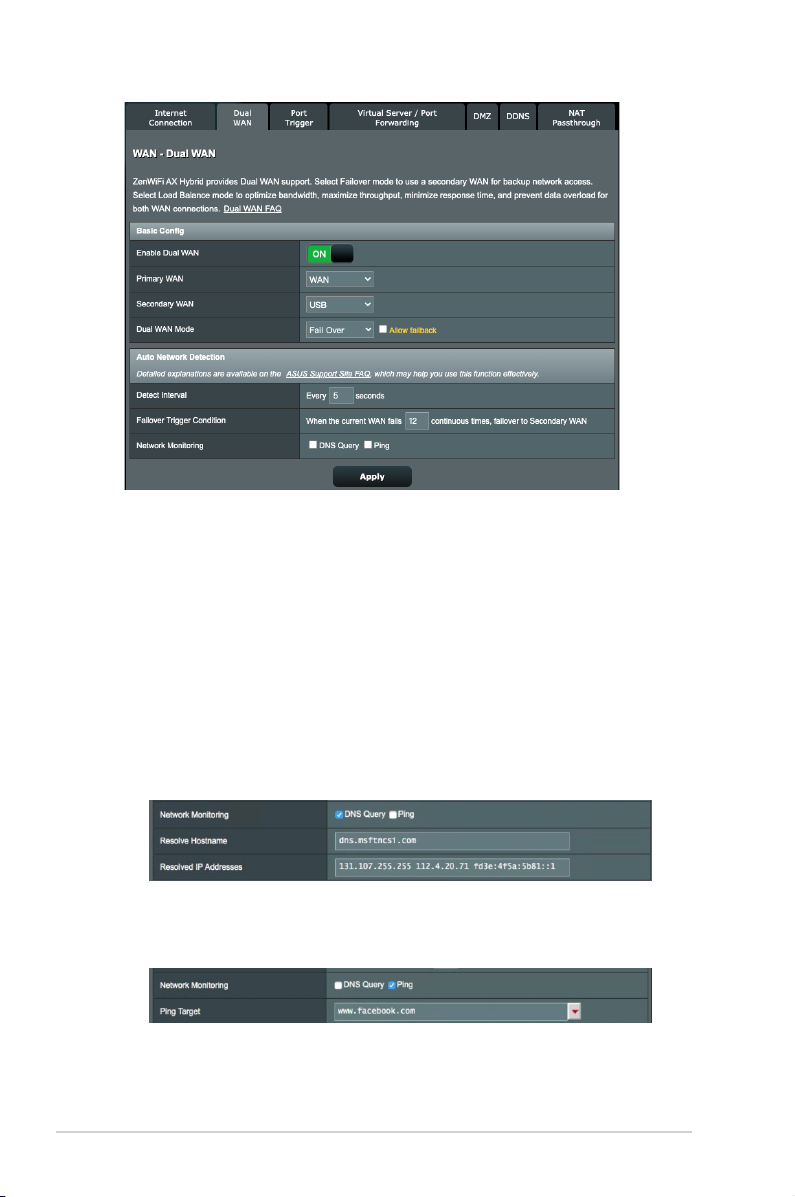
• Detect Interval: Set the time interval (in seconds) between
two ping packets.
• Failover Trigger Condition: Set the continuous times when
the system triggers the failover or failback action after
reaching the ping test counter and getting no response from
the target IP address.
• Network Monitoring
1) DNS Query: Select this option if you want to periodically
resolve target FQDN (Fully Qualied Domain Name).
2) Ping: Select this option if you want to periodically ping test
packet domain or IP address.
If internet connection issue occurs due to DHCP lease problem
such as IP address being expired, you can enable DNS Query or
Ping to alleviate the problem.
80
Page 81
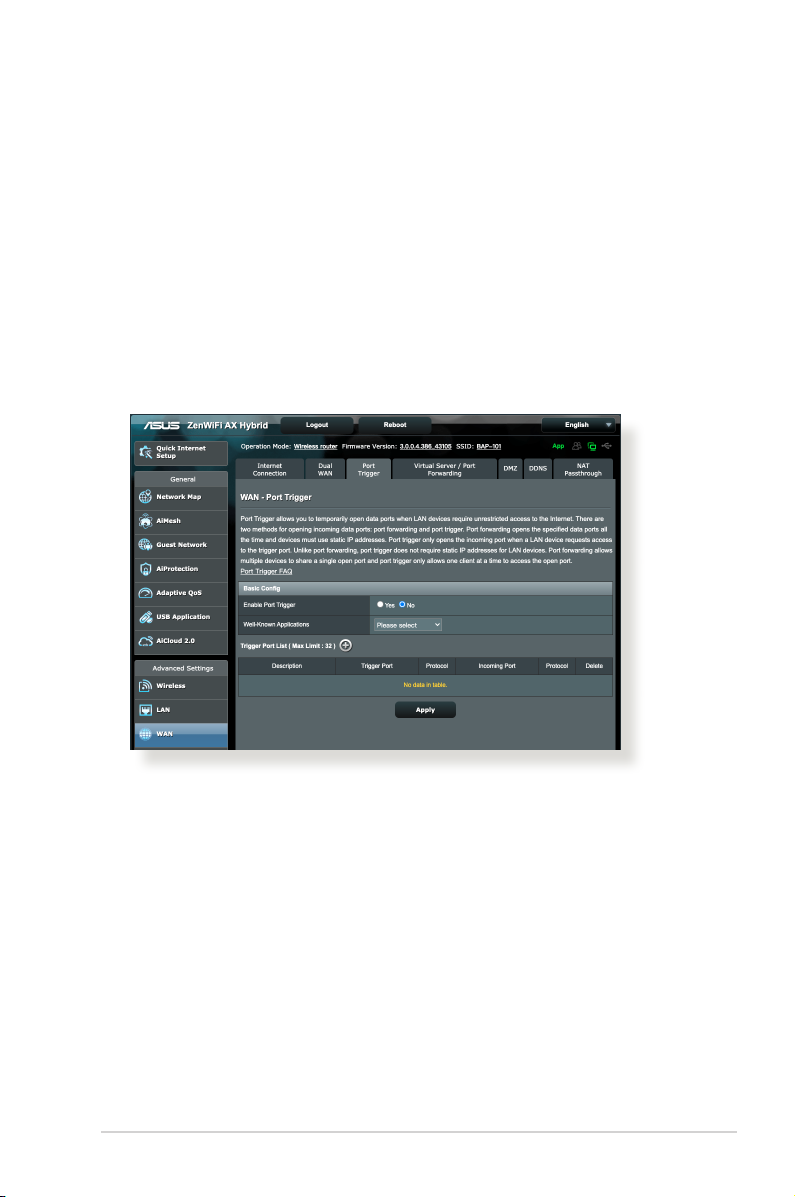
4.3.3 Port Trigger
Port range triggering opens a predetermined incoming port for a
limited period of time whenever a client on the local area network
makes an outgoing connection to a specied port. Port triggering
is used in the following scenarios:
• More than one local client needs port forwarding for the
same application at a dierent time.
• An application requires specic incoming ports that are
dierent from the outgoing ports.
To set up Port Trigger:
1. From the navigation panel, go to Advanced Settings > WAN >
Port Trigger tab.
2. Congure the following settings below. When done, click
Apply.
• Enable Port Trigger: Choose Yes to enable Port Trigger.
• Well-Known Applications: Select popular games and web
services to add to the Port Trigger List.
• Description: Enter a short name or description for the service.
81
Page 82

• Trigger Port: Specify a trigger port to open the incoming
port.
• Protocol: Select the protocol, TCP, or UDP.
• Incoming Port: Specify an incoming port to receive inbound
data from the Internet.
NOTES:
• When connecting to an IRC server, a client PC makes an outgoing
connection using the trigger port range 66660-7000. The IRC server
responds by verifying the username and creating a new connection
to the client PC using an incoming port.
• If Port Trigger is disabled, the router drops the connection because
it is unable to determine which PC is requesting for IRC access.
When Port Trigger is enabled, the router assigns an incoming port to
receive the inbound data. This incoming port closes once a specic
time period has elapsed because the router is unsure when the
application has been terminated.
• Port triggering only allows one client in the network to use a
particular service and a specic incoming port at the same time.
• You cannot use the same application to trigger a port in more than
one PC at the same time. The router will only forward the port back
to the last computer to send the router a request/trigger.
82
Page 83
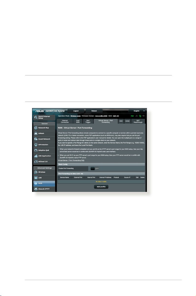
4.3.4 Virtual Server / Port Forwarding
Port forwarding is a method to direct network trac from the
Internet to a specic port or a specic range of ports to a device
or number of devices on your local network. Setting up Port
Forwarding on your router allows PCs outside the network to
access specic services provided by a PC in your network.
NOTE: When port forwarding is enabled, the ASUS router blocks
unsolicited inbound trac from the Internet and only allows replies
from outbound requests from the LAN. The network client does not
have access to the Internet directly, and vice versa.
To set up Port Forwarding:
1. From the navigation panel, go to Advanced Settings > WAN >
Virtual Server / Port Forwarding tab.
2. Slide the bar to ON to enable Port Forwarding, then click Add
Prole. After conguring the following settings, click OK.
83
Page 84
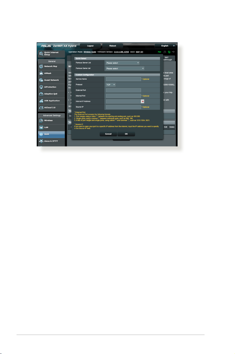
• Famous Server List: Determine which type of service you
want to access.
• Famous Game List: This item lists ports required for popular
online games to work correctly.
• Service Name: Enter a service name.
• Protocol: Select the protocol. If you are unsure, select BOTH.
• External Port: Accept the following formats:
1) A port range using a colon “:” in the middle to specify the
upper and lower limits of the range, such as 300:350;
2) Individual port numbers using a comma “,” to separate
them, such as 566, 789;
3) A Mix of port ranges and individual ports, using colons “:”
and commas “,”, such as 1015:1024, 3021.
• Internal Port: Enter a specic port to receive forwarded
packets. Leave this eld blank if you want the incoming
packets to be redirected to the specied port range.
84
Page 85

• Internal IP Address: Key in the client’s LAN IP address.
• Source IP: If you want to open your port to a specic IP
address from the Internet, input the IP address you want to
give access to in this eld.
NOTE: Use a static IP address for the local client to make port
forwarding work properly. Refer to section 4.2 LAN for information.
To check if Port Forwarding has been congured successfully:
• Ensure that your server or application is set up and running.
• You will need a client outside your LAN but has Internet
access (referred to as “Internet client”). This client should not
be connected to the ASUS router.
• On the Internet client, use the router’s WAN IP to access the
server. If port forwarding has been successful, you should be
able to access the les or applications.
Dierences between port trigger and port forwarding:
• Port triggering will work even without setting up a specic
LAN IP address. Unlike port forwarding, which requires a
static LAN IP address, port triggering allows dynamic port
forwarding using the router. Predetermined port ranges are
congured to accept incoming connections for a limited
period of time. Port triggering allows multiple computers
to run applications that would normally require manually
forwarding the same ports to each PC on the network.
• Port triggering is more secure than port forwarding since the
incoming ports are not open all the time. They are opened
only when an application is making an outgoing connection
through the trigger port.
85
Page 86

4.3.5 DMZ
Virtual DMZ exposes one client to the Internet, allowing this
client to receive all inbound packets directed to your Local Area
Network.
Inbound trac from the Internet is usually discarded and routed
to a specic client only if port forwarding or a port trigger has
been congured on the network. In a DMZ conguration, one
network client receives all inbound packets.
Setting up DMZ on a network is useful when you need incoming
ports open or you want to host a domain, web, or e-mail server.
CAUTION: Opening all the ports on a client to the Internet makes the
network vulnerable to outside attacks. Please be aware of the security
risks involved in using DMZ.
To set up DMZ:
1. From the navigation panel, go to Advanced Settings > WAN >
DMZ tab.
2. Congure the setting below. When done, click Apply.
• IP address of Exposed Station: Key in the client’s LAN IP
address that will provide the DMZ service and be exposed
on the Internet. Ensure that the server client has a static IP
address.
To remove DMZ:
1. Delete the client’s LAN IP address from the IP Address of
Exposed Station text box.
2. When done, click Apply.
86
Page 87
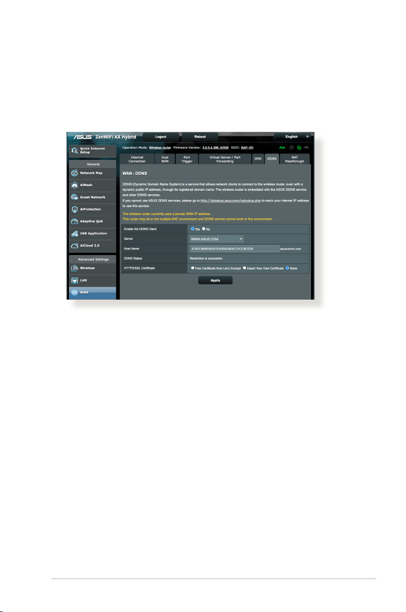
4.3.6 DDNS
Setting up DDNS (Dynamic DNS) allows you to access the router
from outside your network through the provided ASUS DDNS
Service or another DDNS service.
To set up DDNS:
1. From the navigation panel, go to Advanced Settings > WAN >
DDNS tab.
2. Congure the following settings below. When done, click
Apply.
• Enable the DDNS Client: Enable DDNS to access the ASUS
router via the DNS name rather than WAN IP address.
• Server and Host Name: Choose ASUS DDNS or other DDNS.
If you want to use ASUS DDNS, ll in the Host Name in the
format of xxx.asuscomm.com (xxx is your host name).
• If you want to use a dierent DDNS service, click FREE TRIAL
and register online rst. Fill in the User Name or E-mail
Address and Password or DDNS Key elds.
• Enable wildcard: Enable wildcard if your DDNS service
requires one.
87
Page 88
NOTES:
DDNS service will not work under these conditions:
• When the wireless router is using a private WAN IP address (192.168.
x.x, 10.x.x.x, or 172.16.x.x), as indicated by a yellow text.
• The router may be on a network that uses multiple NAT tables.
4.3.7 NAT Passthrough
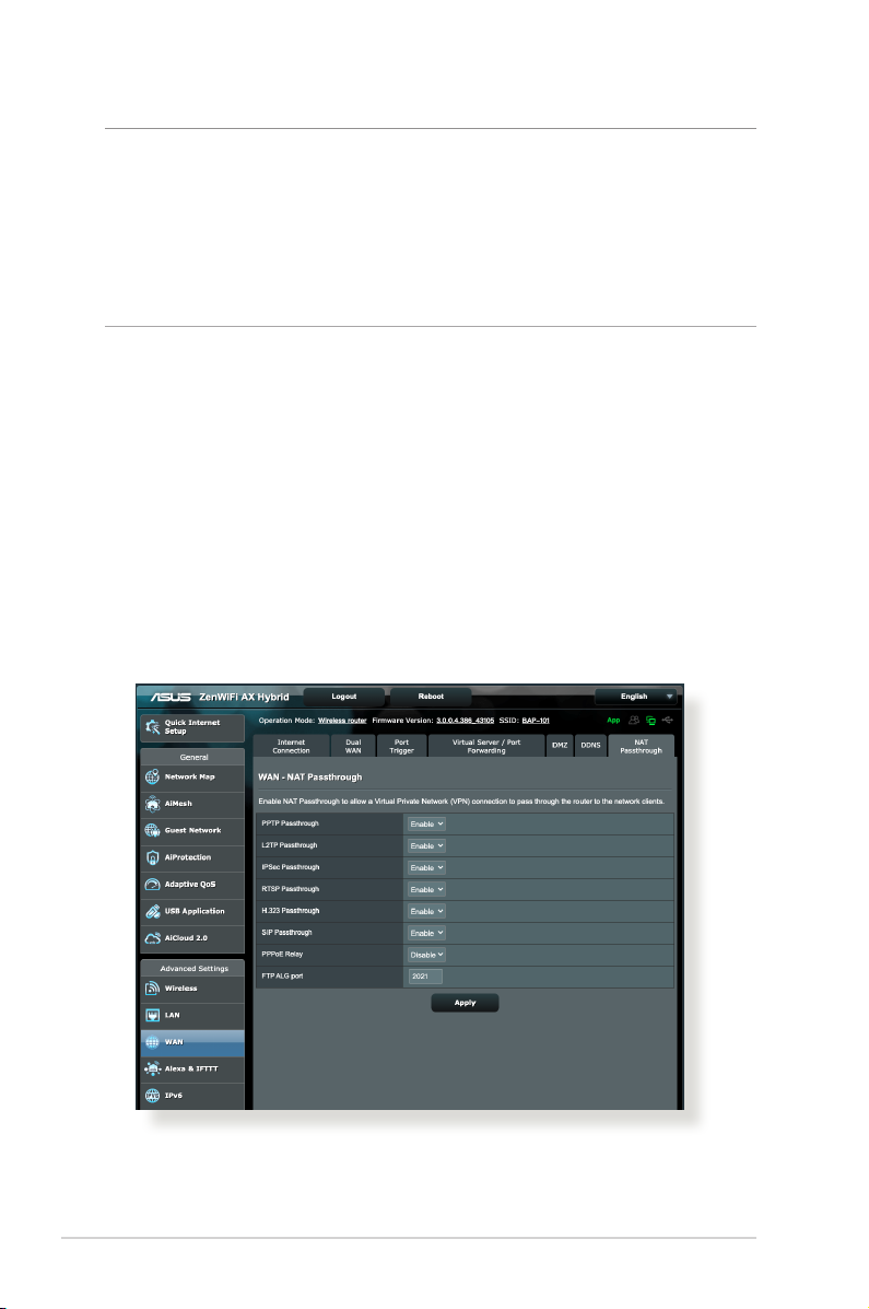
NAT Passthrough allows a Virtual Private Network (VPN)
connection to pass through the router to the network clients.
PPTP Passthrough, L2TP Passthrough, IPsec Passthrough and RTSP
Passthrough are enabled by default.
To enable / disable the NAT Passthrough settings, go to the
Advanced Settings > WAN > NAT Passthrough tab. When done,
click Apply.
88
Page 89
4.4 IPv6
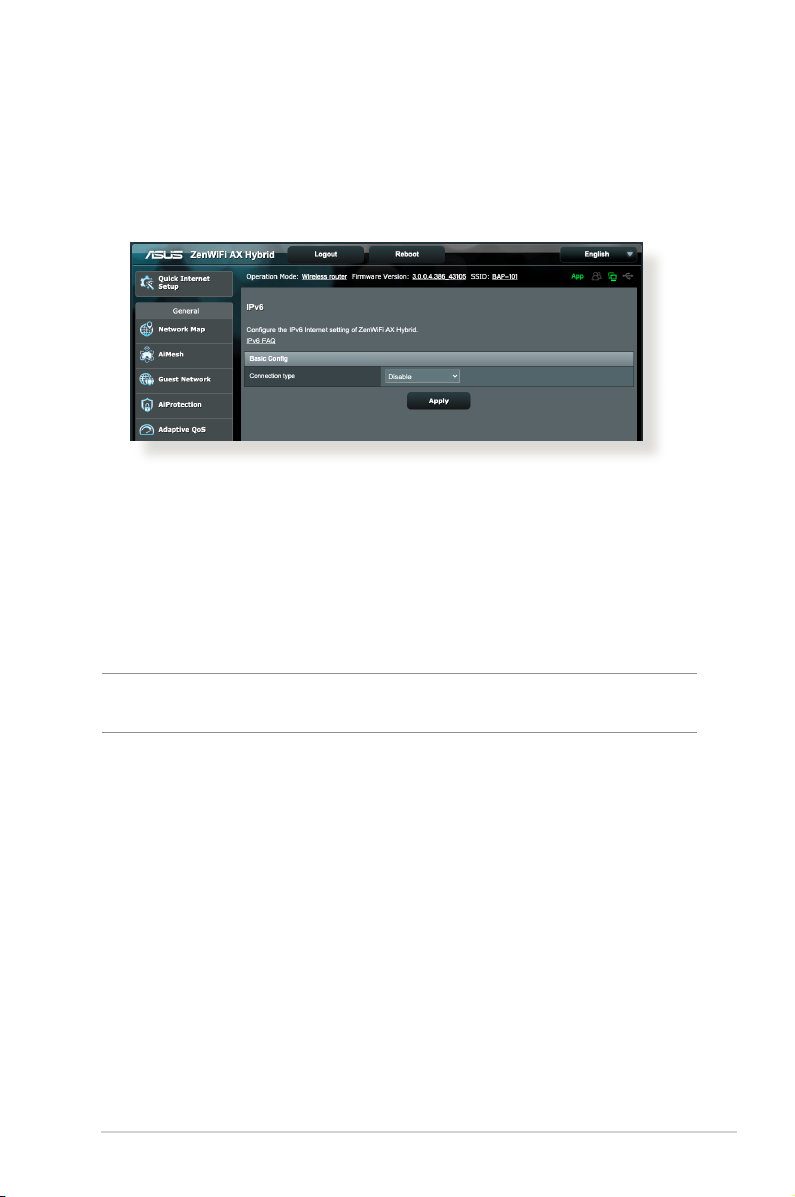
This wireless router supports IPv6 addressing, a system that
supports more IP addresses. This standard is not yet widely
available. Contact your ISP if your Internet service supports IPv6.
To set up IPv6:
1. From the navigation panel, go to Advanced Settings > IPv6.
2. Select your Connection type. The conguration options vary
depending on your selected connection type.
3. Enter your IPv6 LAN and DNS settings.
4. Click Apply.
NOTE: Please refer to your ISP regarding specic IPv6 information for
your Internet service.
89
Page 90

4.5 Firewall
The wireless router can serve as a hardware rewall for your
network.
NOTE: The Firewall feature is enabled by default.
4.5.1 General
To set up basic Firewall settings:
1. From the navigation panel, go to Advanced Settings >
Firewall > General tab.
2. On the Enable Firewall eld, select Yes.
3. On the Enable DoS protection, select Yes to protect your
network from DoS (Denial of Service) attacks though this may
aect your router’s performance.
4. You can also monitor packets exchanged between the LAN
and WAN connection. On the Logged packets type, select
Dropped, Accepted, or Both.
5. Click Apply.
4.5.2 URL Filter
You can specify keywords or web addresses to prevent access to
specic URLs.
NOTE: The URL Filter is based on a DNS query. If a network client has
already accessed a website such as http://www.abcxxx.com, then the
website will not be blocked (a DNS cache in the system stores previously
visited websites). To resolve this issue, clear the DNS cache before
setting up the URL Filter.
90
Page 91
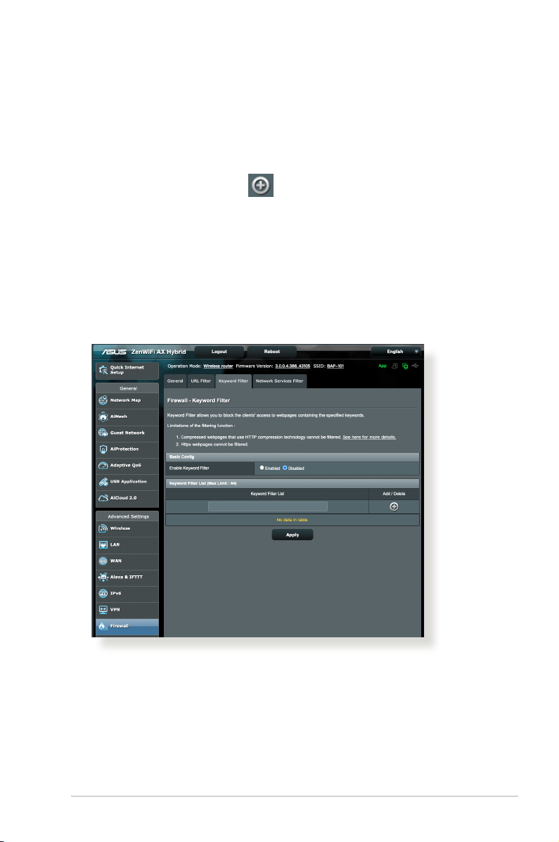
To set up a URL lter:
1. From the navigation panel, go to Advanced Settings >
Firewall > URL Filter tab.
2. On the Enable URL Filter eld, select Enabled.
3. Enter a URL and click the button.
4. Click Apply.
4.5.3 Keyword lter
Keyword lter blocks access to webpages containing specied
keywords.
To set up a keyword lter:
1. From the navigation panel, go to Advanced Settings >
Firewall > Keyword Filter tab.
2. On the Enable Keyword Filter eld, select Enabled.
91
Page 92
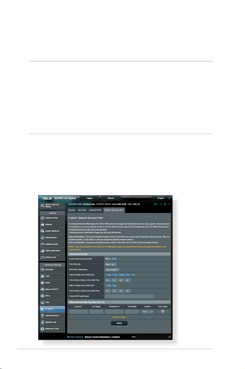
3. Enter a word or phrase and click the Add button.
4. Click Apply.
NOTES:
• The Keyword Filter is based on a DNS query. If a network client has
already accessed a website such as http://www.abcxxx.com, then
the website will not be blocked (a DNS cache in the system stores
previously visited websites). To resolve this issue, clear the DNS cache
before setting up the Keyword Filter.
• Web pages compressed using HTTP compression cannot be ltered.
HTTPS pages also cannot be blocked using a keyword lter.
4.5.4 Network Services Filter
The Network Services Filter blocks LAN to WAN packet exchanges
and restricts network clients from accessing specic web services
such as Telnet or FTP.
92
Page 93

To set up a Network Service lter:
1. From the navigation panel, go to Advanced Settings >
Firewall > Network Services Filter tab.
2. On the Enable Network Services Filter eld, select Yes.
3. Select the Filter table type. Deny List blocks the specied
network services. Allow List limits access to only the specied
network services.
4. Specify the day and time when the lters will be active.
5. To specify a Network Service to lter, enter the Source IP,
Destination IP, Port Range, and Protocol. Click the button.
6. Click Apply.
93
Page 94
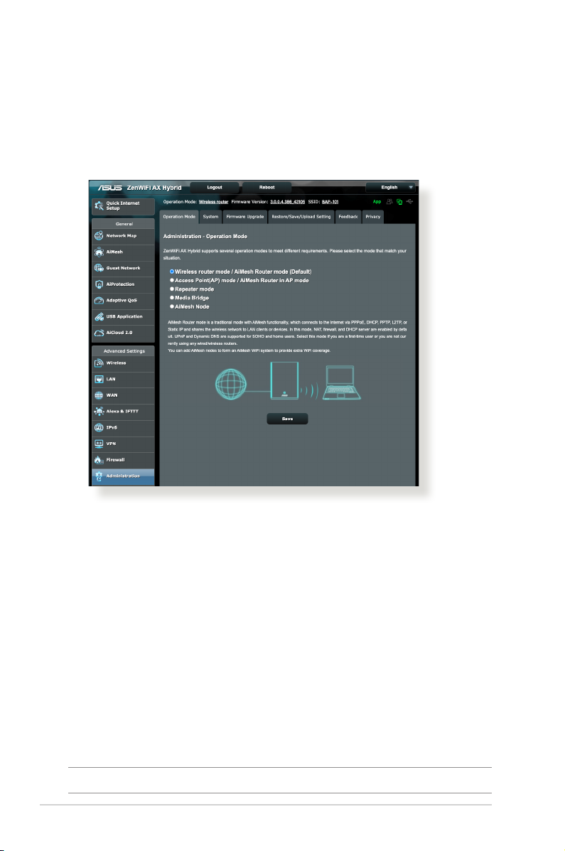
4.6 Administration
4.6.1 Operation Mode
The Operation Mode page allows you to select the appropriate
mode for your network.
To set up the operating mode:
1. From the navigation panel, go to Advanced Settings >
Administration > Operation Mode tab.
2. Select any of these operation modes:
• Wireless router mode / AiMesh Router mode (Default):
In wireless router mode, the wireless router connects to the
Internet and provides Internet access to available devices on
its own local network.
• Repeater mode: This mode turns the router into a wireless
repeater to extend the range of your signal.
• Access Point mode: In this mode, the router creates a new
wireless network on an existing network.
3. Click Save.
NOTE: The router will reboot when you change the modes.
94
Page 95

4.6.2 System
The System page allows you to congure your wireless router
settings.
To set up the System settings:
1. From the navigation panel, go to Advanced Settings >
Administration > System tab.
2. You can congure the following settings:
• Change router login password: You can change the
password and login name for the wireless router by entering
a new name and password.
• USB setting: You can Enable HDD Hibernation and change
USB mode.
• WPS button behavior: The physical WPS button on the
wireless router can be used to activate WPS.
• Time Zone: Select the time zone for your network.
• NTP Server: The wireless router can access a NTP (Network
time Protocol) server in order to synchronize the time.
• Network Monitoring: You can enable DNS Query to check
Resolve Hostname and Resolved IP Addresses, or enable
Ping, then check your Ping Target.
• Auto Logout: You can set the time of auto-logout.
• Enable WAN down browser redirect notice: This feature
allows the browser to display a warning page when the
router is disconnected from Internet. When disabled, the
warning page will not appear.
• Enable Telnet: Click Yes to enable Telnet services on the
network. Click No to disable Telnet.
• Authentication Method: You can select HTTP, HTTPS, or
both protocols to secure router access.
• Enable Reboot Scheduler: When enabled, you can set the
Date to Reboot and Time of Day to Reboot.
• Enable Web Access from WAN: Select Ye s to allow devices
outside the network to access the wireless router GUI
settings. Select No to prevent access.
95
Page 96

• Enable Access Restrictions: Click Yes if you want to specify
the IP addresses of devices that are allowed to access to the
wireless router GUI settings from WAN/LAN.
• Service: This feature allows you to congure Enable Telnet/
Enable SSH/SSH Port/Allow Password Login/Authorized
Keys/Idle Timeout.
3. Click Apply.
96
Page 97

4.6.3 Firmware Upgrade
NOTE: Download the latest rmware from the ASUS website at
http://www.asus.com.
To upgrade the rmware:
1. From the navigation panel, go to Advanced Settings >
Administration > Firmware Upgrade tab.
2. In the New Firmware File eld, click Browse to locate the
downloaded le.
3. Click Upload.
NOTES:
• When the upgrade process is complete, wait for some time for the
system to reboot.
• If the upgrade process fails, the wireless router automatically enters
rescue mode and the power LED indicator on the front panel starts
ashing slowly. To recover or restore the system, refer to section 5.2
Firmware Restoration.
4.6.4 Restore/Save/Upload Setting
To restore/save/upload wireless router settings:
1. From the navigation panel, go to Advanced Settings >
Administration > Restore/Save/Upload Setting tab.
2. Select the tasks that you want to do:
• To restore to the default factory settings, click Restore, and
click OK in the conrmation message.
• To save the current system settings, click Save, navigate to
the folder where you intend to save the le and click Save.
• To restore from a saved system settings le, click Browse to
locate your le, then click Upload.
IMPORTANT! If issues occur, upload the latest rmware version and
congure new settings. Do not restore the router to its default settings.
97
Page 98
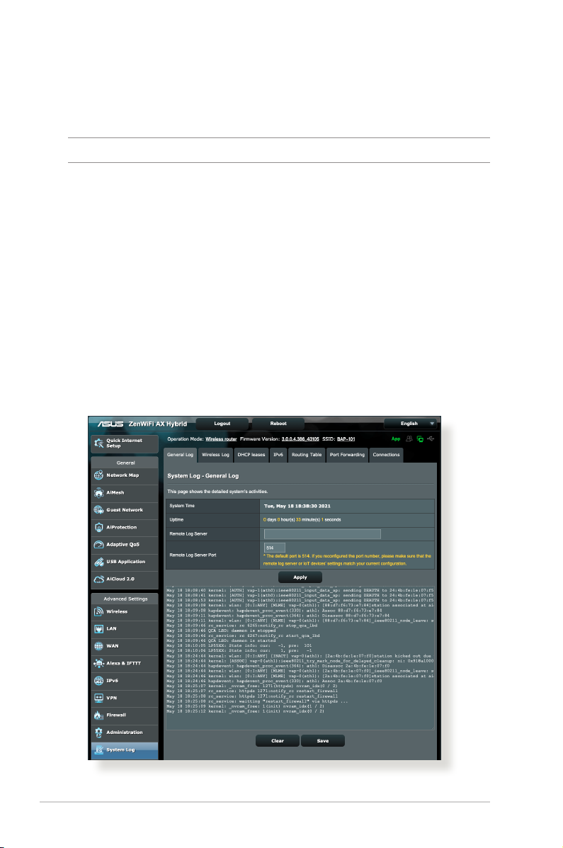
4.7 System Log
System Log contains your recorded network activities.
NOTE: System log resets when the router is rebooted or powered o.
To view your system log:
1. From the navigation panel, go to Advanced Settings > System
Log.
2. You can view your network activities in any of these tabs:
• General Log
• Wireless Log
• DHCP leases
• IPv6
• Routing Table
• Port Forwarding
• Connections
98
Page 99
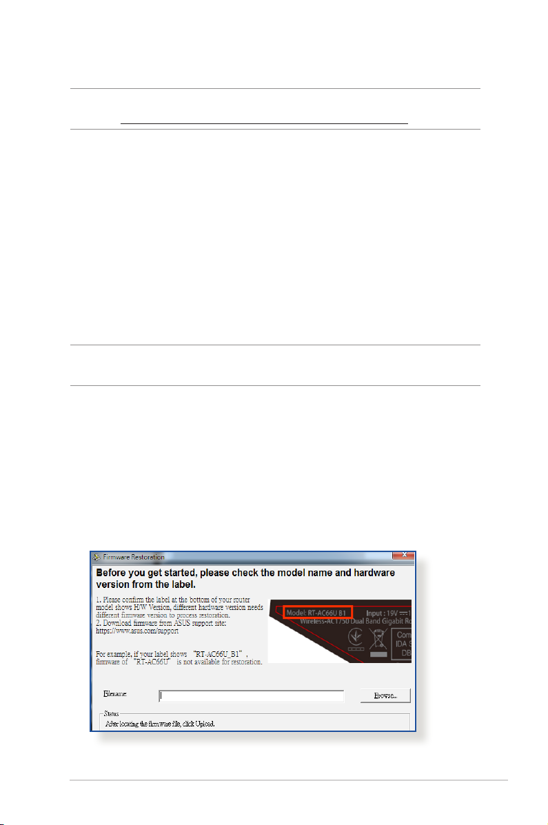
5 Utilities5 Utilities
NOTE: Download and install the wireless router’s utilities from the ASUS
website: https://www.asus.com/support/Download-Center/
5.1 Device Discovery
Device Discovery is an ASUS WLAN utility that detects an ASUS
wireless router device, and allows you to congure the wireless
networking settings.
To launch the Device Discovery utility:
• From your computer’s desktop, click
Start > All Programs > ASUS Utility > Wireless Router >
Device Discovery.
NOTE: When you set the router to Access Point mode, you need to use
Device Discovery to get the router’s IP address.
5.2 Firmware Restoration
Firmware Restoration is used on an ASUS Wireless Router that
failed during its rmware upgrading process. It uploads the
rmware that you specify. The process takes about three to four
minutes.
99
Page 100

IMPORTANT! Launch the rescue mode on the router before using
the Firmware Restoration utility.
To launch the rescue mode and use the Firmware Restoration
utility:
1. Unplug the wireless router from the power source.
2. Hold the Reset button at the rear panel and simultaneously
replug the wireless router into the power source. Release the
Reset button when the Power LED at the front panel ashes
slowly, which indicates that the wireless router is in the rescue
mode.
3. Set a static IP on your computer and use the following to set up
your TCP/IP settings:
IP address: 192.168.1.x
Subnet mask: 255.255.255.0
4. From your computer’s desktop, click
Start > All Programs > ASUS Utility > Wireless Router >
Firmware Restoration.
5. Specify a rmware le, then click Upload.
NOTE: This is not a rmware upgrade utility and cannot be used on
a working ASUS Wireless Router. Normal rmware upgrades must be
done through the web interface. Refer to Chapter 4: Conguring the
Advanced Settings for more details.
100
 Loading...