

ASUS W5F Service Manual

Disassembly Procedure
A
Chapter
Disassembly Procedure
Please follow the information provided in this section to perform the complete
disassembly procedure of the notebook. Be sure to use proper tools
described before.
SUS W5F Series Notebook consists of various modules. This chapter describes the
procedures for the complete notebook disassembly. In addition, in between procedures,
the detailed disassembly procedure of individual modules will be provided for your
service needs.
The disassembly procedure consists of the following steps:
• Battery Module
• HDD Module
• Second Memory Module
• CPU Module
• Optical Drive Module
• Keyboard Module
• First Memory Module
• LCD Module
• Top Case Module
• Motherboard Module
• Mini PCI Module
2 - 1
BATTERY
Disassembly Procedure
Battery Module
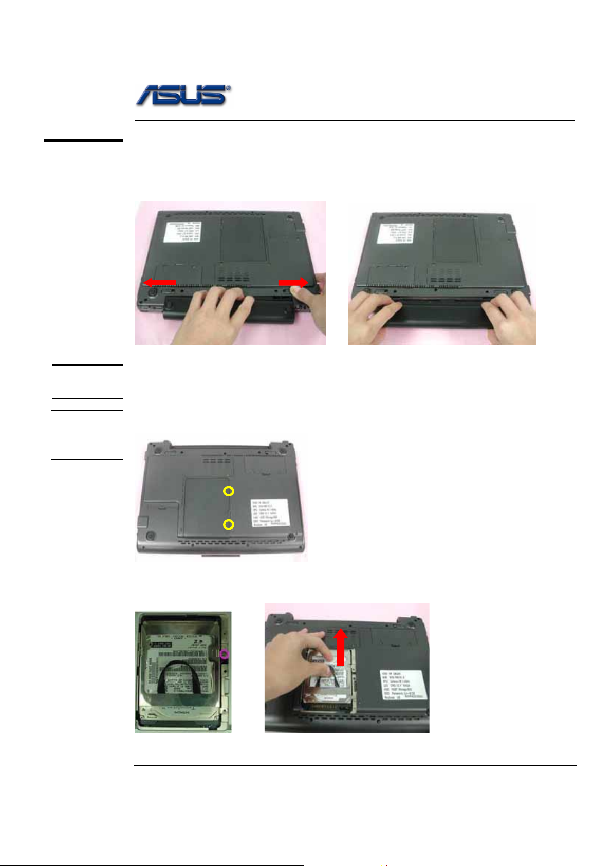
The illustration below shows how to remove the battery module.
1. Press latch to open the battery module, then lift battery module away from the
system.
HDD
MODULE
HDD Module
The illustrations below show how to remove the HDD module from the notebook.
HDD
MODULE
REMOVAL
Removing HDD Module
1. Remove 2 screws (M2*5L(K)), then remove the HDD door.
M2*5L
2. Remove 1 screw (M2*12L(K)), lift the hard disk module and take away the hard
disk module
2 - 2
Disassembly Procedure
SECOND
MEMORY
MODULE
MEMORY
REMOVAL
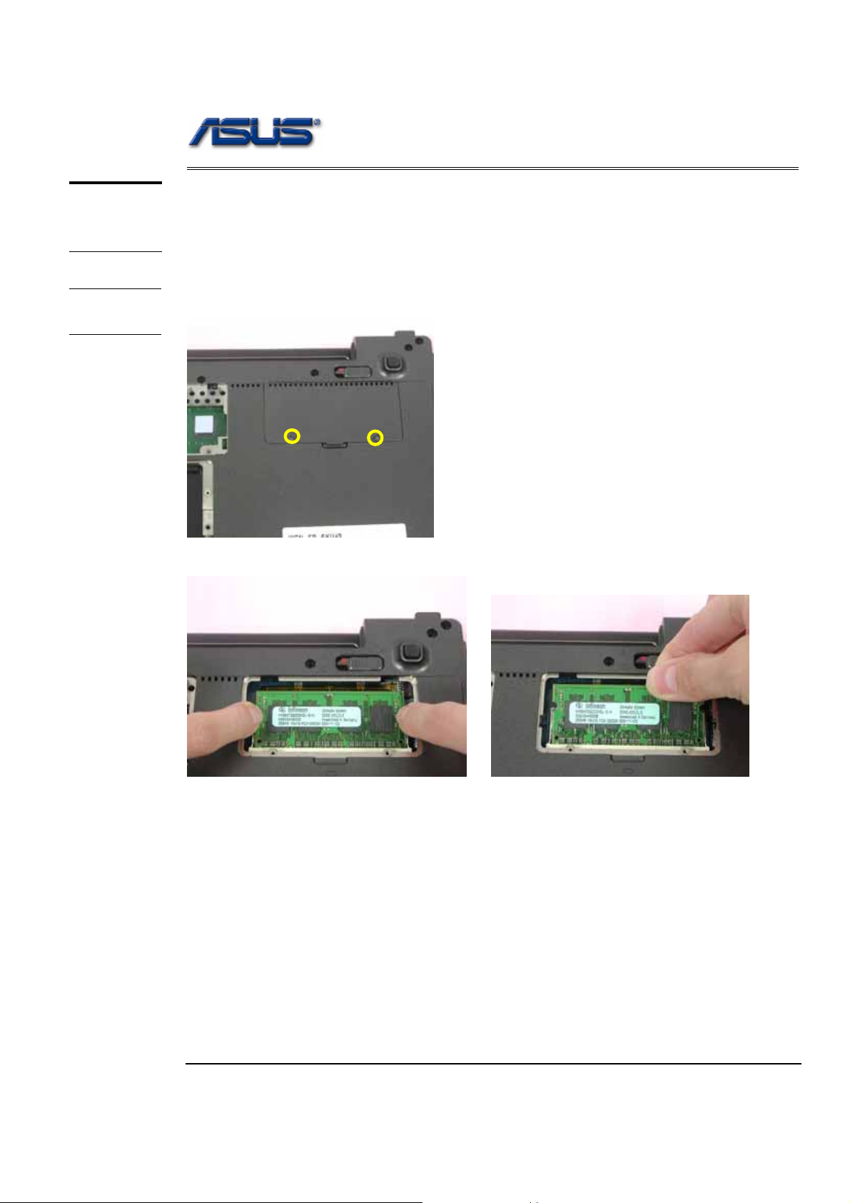
Memory Module
The W5F Series Notebook have onboard RAM. There is one SO-DIMM sockets for
installing SO-DIMM RAM. It can upgrade the total memory size up to 1GB with a
512MB module on each socket.
Removing Memory module
1. Remove 2 screws (M2*4L(K)), then remove the Memory cover.
M2*4L
2. Pop the module up to a 45° angles, and then pulling out the module in that angle.
2 - 3
Disassembly Procedure
CPU MODULE
REMOVAL
CPU
REMOVAL
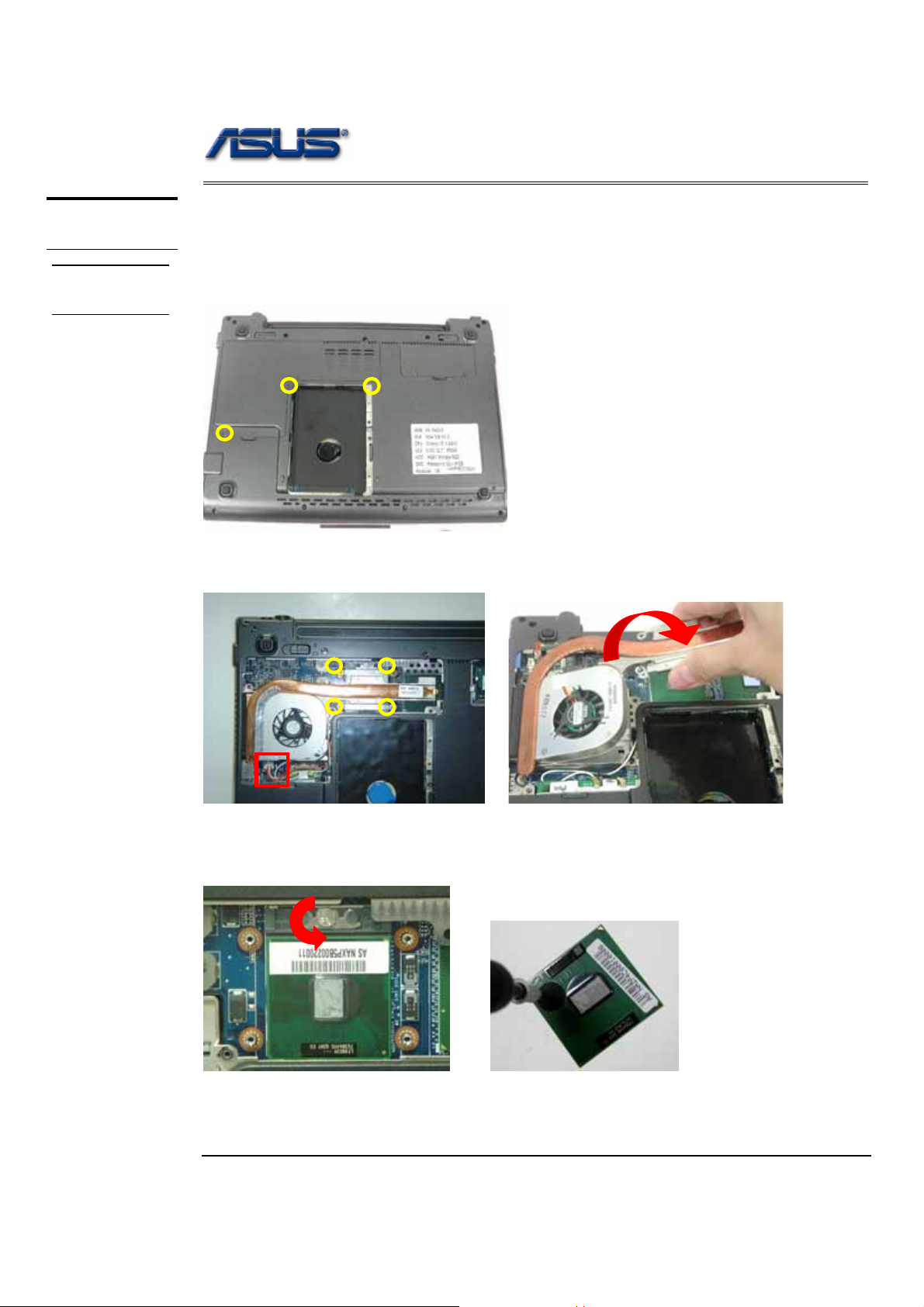
CPU Module
The illustrations below show how to remove the CPU module from the notebook.
Removing CPU Module
1. Remove 3 screws (M2*4L(K)), then remove the back cover.
M2*4L
2. Remove 4 screws (M2* 4L(K)) and disconnect the FA N connector and then take
away the Fan Module.
M2*4L
3. Turn the non-removable screw here 180 degrees counter-clockwise to loosen the
CPU and take the CPU away
Note: If thermal module has no thermal pad on it, please plus a thermal pad
on the CPU die before assembling.
2 - 4
Disassembly Procedure
OPTICAL
DRIVE
REMOVAL
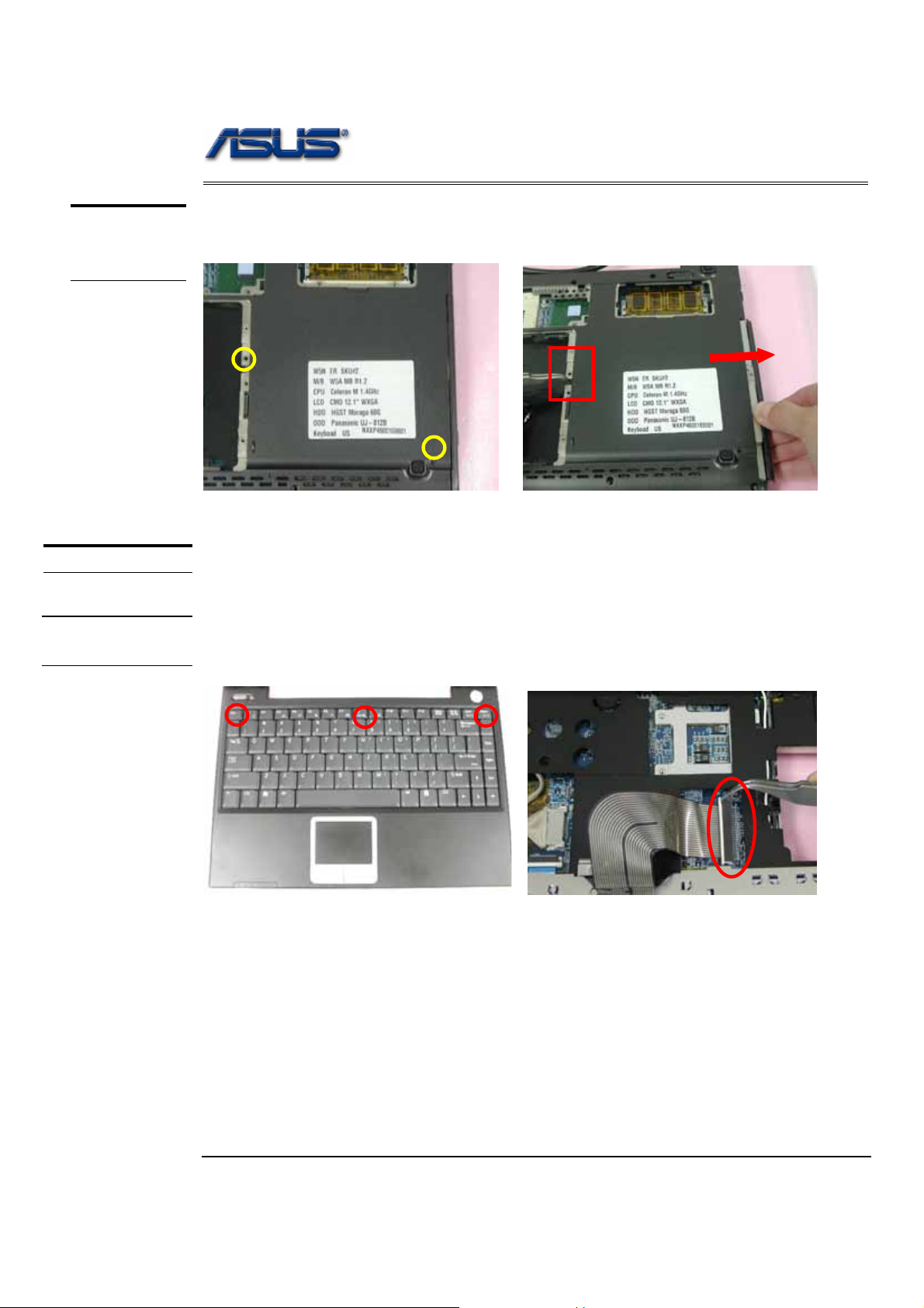
Optical Drive Module
Remove 3 screws and use tweezers to put the Optical Drive Module out.
M2*4L
KEYBOARD
Keyboard Module
The illustration of below shows how to remove the keyboard
K/B COVER
REMOVAL
Removing Keyboard Cover
1. Unlock 3 keyboard latches then pull out the keyboard forward and lay the keyboard
on the front side then disconnect the FPC.
2 - 5
 Loading...