How it Works
Log In / Sign Up
Buy Points
How it Works
FAQ
Contact Us
Questions and Suggestions
Users
Asus
Loading...
V
VK246H
6
VK246U
5
VK248
2
VK248H
13
VK248HL
11
VK248 series
VK266
5
VK266H
29
VK276Q
30
VK278
VK278Q
30
VK278Q Series
16
VL249HE
2
VL278
VL278H
27
VL279HE
28
VL I-486SV2G
2
VL/I-486SV2GX4
VM400CP
29
VM400VP
29
VM40B
34
VM410LD
26
VM410MD
30
VM42
28
VM42-S232Z
VM45
VM480LN
31
VM490LN
26
VM510LD
56
VM510LF
25
VM510LI
34
VM510LJ
25
VM510LP
34
VM510UA
32
VM520UP
32
VM580L
VM590LB
25
VM590LJ
25
VM590LN
54
VM590UA
32
VM590UB
31
VM590ZE
33
VM591D
2
VM591UF
29
VM591UR
30
VM591UV
31
VM592UJ
32
VM60
28
VM62
28
VM62N
28
VM65
42
VM65N
40
VM65N-G071M
VN247
32
VN247H
31
VN247HA
32
VN247H-P
28
VN247N
VN247NA
32
VN248
30
VN248H
31
VN248HA
32
VN248H-P
30
VN248NA
31
VN248QA
31
VN248Q-P
30
VN279
8
VN279H
13
VN279Q
13
VN279QL
12
VN279QLB
13
VN279-reeks
VN279 series
3
VN289
30
VN289H
3
VN289N-W
2
VN289Q
31
VN289QL
2
VN289QR
VN6072
VP228
2
VP228DE
13
VP228H
14
VP228HE
15
VP228N
11
VP228NE
11
VP228QG
16
VP228T
11
VP228TE
11
VP229DA
16
VP229HA
16
VP229HAL
16
VP229HE
25
VP229HEY
23
VP229NA
15
VP229Q
25
VP229TA
16
VP239H
13
VP239H-P
13
VP239T
13
Loading...
Loading...
Nothing found
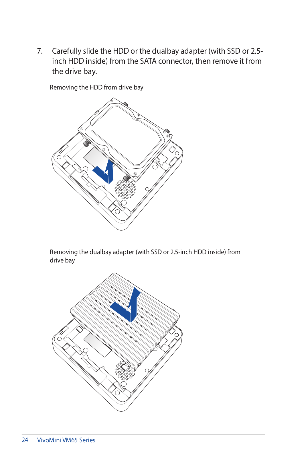
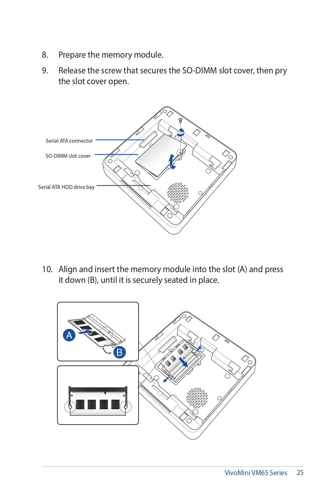
VM65
User’s Manual
12 pgs
1.15 Mb
0
User’s Manual
38 pgs
3.08 Mb
0
User’s Manual
40 pgs
3.36 Mb
0
User’s Manual
44 pgs
3.49 Mb
0
User’s Manual
54 pgs
4.93 Mb
0
User’s Manual
38 pgs
3.84 Mb
0
User’s Manual [ar]
40 pgs
3.29 Mb
0
User’s Manual [cs]
36 pgs
3.09 Mb
0
User’s Manual [da]
40 pgs
3.06 Mb
0
User’s Manual [da]
36 pgs
3.01 Mb
0
User’s Manual [de]
38 pgs
3.76 Mb
0
User’s Manual [el]
36 pgs
3.09 Mb
0
User’s Manual [es]
38 pgs
3.07 Mb
0
User’s Manual [fi]
36 pgs
3.69 Mb
0
User’s Manual [fr]
82 pgs
5.79 Mb
0
User’s Manual [fr]
40 pgs
3.09 Mb
0
User’s Manual [hu]
40 pgs
3.07 Mb
0
User’s Manual [hu]
36 pgs
3.02 Mb
0
User’s Manual [id]
44 pgs
3.25 Mb
0
User’s Manual [id]
40 pgs
3.04 Mb
0
User’s Manual [it]
41 pgs
3.14 Mb
0
User’s Manual [it]
38 pgs
3.77 Mb
0
User’s Manual [ja]
42 pgs
3.27 Mb
0
User’s Manual [ko]
40 pgs
2.94 Mb
0
User’s Manual [nl]
36 pgs
3.08 Mb
0
User’s Manual [no ]
36 pgs
3.69 Mb
0
User’s Manual [pt]
36 pgs
3.7 Mb
0
User’s Manual [ro]
36 pgs
3.08 Mb
0
User’s Manual [ru]
40 pgs
3.19 Mb
0
User’s Manual [ru]
38 pgs
3.97 Mb
0
User’s Manual [sk]
40 pgs
3.07 Mb
0
User’s Manual [sv]
36 pgs
3.69 Mb
0
User’s Manual [tr]
60 pgs
4.72 Mb
0
User’s Manual [tr]
12 pgs
632.93 Kb
0
User’s Manual [tr]
44 pgs
3.09 Mb
0
User’s Manual [uk]
37 pgs
3.7 Mb
0
User’s Manual [zh]
12 pgs
1.3 Mb
0
User’s Manual [zh]
46 pgs
3.57 Mb
0
User’s Manual [zh]
14 pgs
1.31 Mb
0
User’s Manual [zh]
44 pgs
3.7 Mb
0
User’s Manual [zh]
56 pgs
5.04 Mb
0
User’s Manual [zh]
54 pgs
5.08 Mb
0
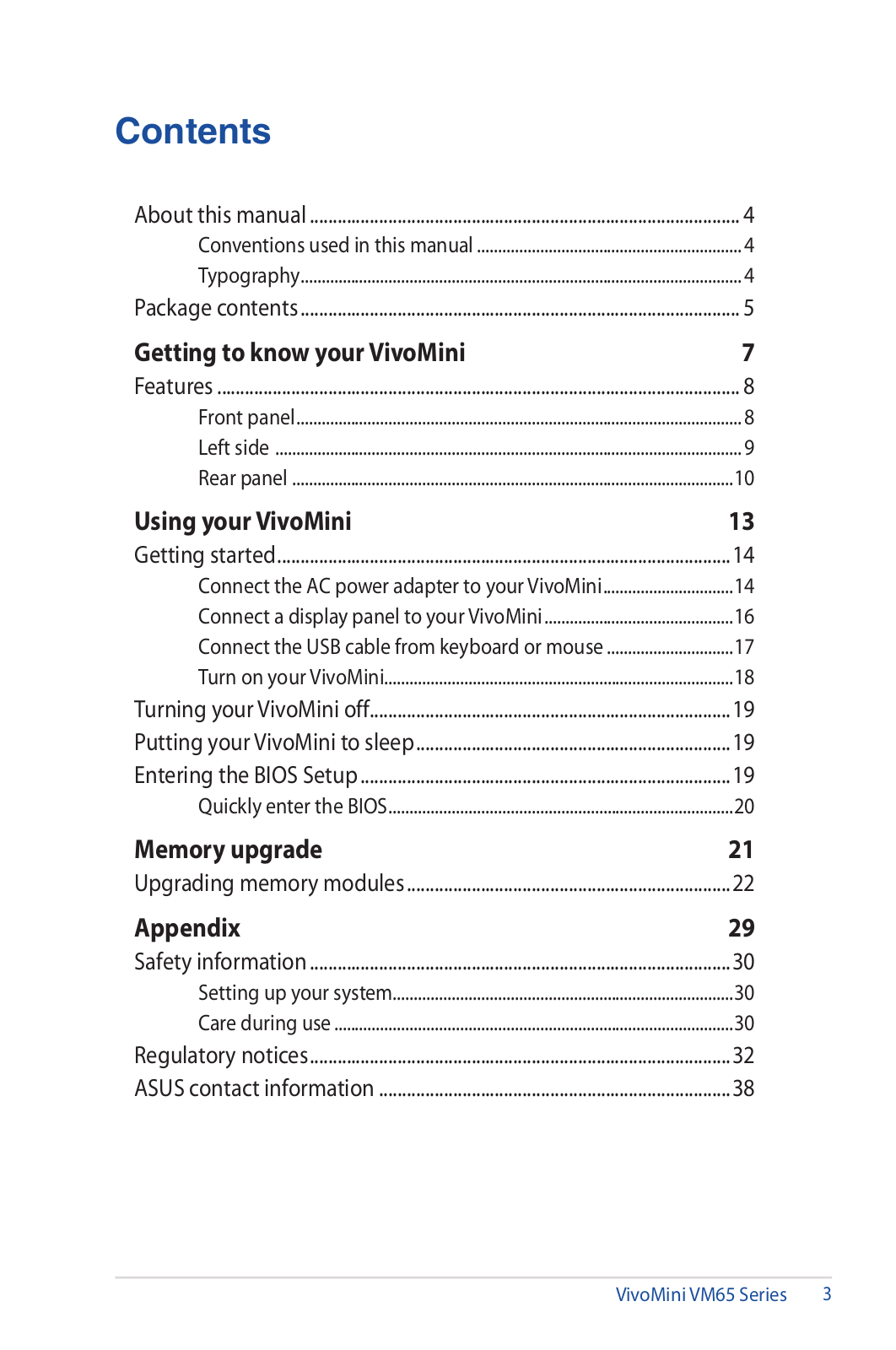
Table of contents
Loading...
Asus VM65 User’s Manual [fr]
...
Asus User’s Manual [fr]
Download
Specifications and Main Features
Frequently Asked Questions
User Manual
Download
Loading...
+
57
hidden pages
Unhide
You need points to download manuals.
1 point = 1 manual.
You can buy points or you can get point for every manual you upload.
Buy points
Upload your manuals
 Loading...