

Page 1
Vintage2-AE1
Page 2
1
2
©2006
: VINTAGE2-AE1
: V1 T2207
: 2006 1
2
Page 3
ASUSTeK COMPUTER INC.
15
886-2-2894-3447
0800-093-456
886-2-2890-7698
tw.asus.com
ASUS COMPUTER INTERNATIONAL
44370 Nobel Drive, Fremont, CA 94538, USA
+1-502-995-0883
+1-502-933-8713
tmdl@asus.com
+1-502-995-0883
+1-502-933-8713
http://vip.asus.com/eservice/techserv.aspx
www.asus.com
ASUS COMPUTER GmbH /
Harkortstr. 25, 40880 Ratingen, BRD, Germany
49-2102-9599-31
sales@asuscom.de
49-2102-9599-0 ...
49-2102-9599-10 ..
49-2102-9599-11
www.asuscom.de/support
www.asuscom.de
3
Page 4
........................................................................................
........................................................................................
........................................................................................
............................................................................................
2
3
7
8
1.1
1.2
1.3
1.4
1.5
2.1
2.2
2.3 CPU
2.4
2.5
2.6
...............................................................................................
...............................................................................
...................................................................................
...................................................................................
...............................................................................
...................................................................................
2.3.1
2.3.2
2.3.3 CPU
2.4.1
2.4.2
2.4.3
2.4.4
2.5.1
2.5.2
2.5.3
2.5.4 PCI
2.5.5 PCI Express x1
2.5.6 AGP 8X
2.5.7 ( )
2.6.1
......................................................................................
...................................................................................
.....................................................................................
.....................................................................................
1-3
1-3
1-4
1-5
1-6
2-3
...............................................................
...................................................................
..................................................................
.....................................................................
..................................................................
..........................................................................
................................................................
................................................................
........................................................................
................................................
.....................................
.........................................................
.......................................
..................................................
.........................................................
........................................................................
2-4
2-5
2-5
2-5
2-6
2-8
2-8
2-8
2-11
2-11
2-12
2-12
2-12
2-13
2-14
2-14
2-14
2-15
2-16
2-16
4
Page 5
2.7
2.8
2.9
2.6.2
2.6.3
........................................................................
........................................................................
.....................................................................
.............................................................................
.............................................................
2-17
2-17
2-18
2-19
2-19
3.1
3.2
3.3
3.3.1
3.3.2 Drivers Menu
3.3.3 Utilities Menu
3.3.4 Make Disk Menu
3.3.5
3.3.6
3.4 ASUS PC Probe II
3.4.1
3.5 Cool n QuietTM
4.1
4.2
4.3
4.4
...............................................................................................
4.4.1
4.4.2
...............................................................................
.......................................................................................
...................................................
......................................................................
.................................................................
..........................................................
.....................................................
...............................................................................
...................................................................................
...............................................................
.................................................................
.............................................................
3-3
3-3
3-4
..........................................
................................
...............................
...................................
......................................
3-4
3-4
3-5
3-7
3-7
3-8
3-9
3-9
3-16
4-3
4-3
4-4
4-6
4-6
4-7
BIOS
5.1 BIOS
5.1.1
5.1.2 AFUDOS BIOS
5.1.3 AFUDOS BIOS
..................................................................
........................................................
..........................................
..................................
5-3
5-3
5-4
5-5
5
Page 6
5.1.4 EZ Flash BIOS
5.1.5 CrashFree BIOS 2 BIOS
5.1.6
5.2 BIOS
5.2.1 BIOS
5.3 Main Menu
5.3.1 System Time [XX:XX:XX]
5.3.2 System Date [XX/XX/XXXX]
5.3.3 Legacy Diskette A [1.44M, 3.5 in.]
5.3.4 IDE
5.3.5 Onboard PCI S-ATA Controller [RAID by Rom]
5.3.6 System Information
5.4 Advanced menu
5.4.1 JumperFree JumperFree Configuration
5.4.2 USB USB Configuration
5.4.3 CPU Configuration
5.4.4 Chipset
5.4.5 OnBoard Devices Configuration
5.4.6 PCI PCI PnP
5.5 Power menu
5.5.1 Suspend Mode [Auto]
5.5.2 Repost Video on S3 Resume [No]
5.5.3 ACPI 2.0 Support [No]
5.5.4 ACPI APIC Support [Enabled]
5.5.5 APM Configuration
5.5.6 Hardware Monitor
5.6 Boot menu
5.6.1 Boot Device Priority
5.6.2 Boot Settings Configuration
5.6.3 Security
5.7 BIOS Exit menu
......................................................................
...........................................................................
..........................................................
...............................................................
.................................................
.....................................................................
....................................................
........................................................
.........................................................
.........................................................
........................................................
............................................................
...................................................
..................................................
....................................
............................................
.....................................
.....................................
..................................
........................................
.......................................
............................................
...............................
.....................
...............
................
.............................
..........
.....................
............................
.................
5-6
5-7
5-9
5-12
5-13
5-15
5-15
5-15
5-15
5-16
5-17
5-17
5-18
5-18
5-19
5-20
5-20
5-26
5-27
5-28
5-28
5-28
5-28
5-28
5-29
5-30
5-32
5-32
5-32
5-34
5-37
6
Page 7
1.
2.
step-by-step
3.
4.
Jumper
5. BIOS
BIOS BIOS
7
Page 8
IC
8
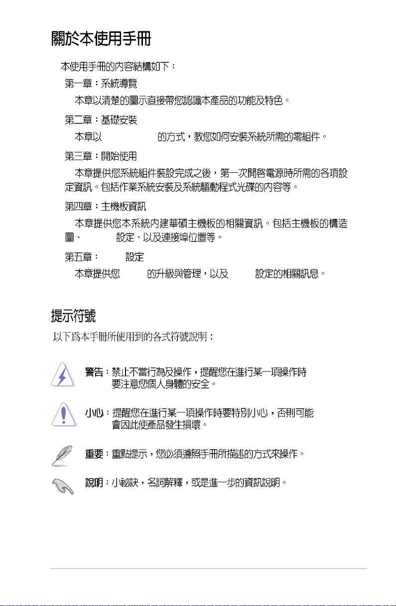
Page 9

Page 10

1.1
1.2
1.3
1.4
1.5
...............................................................................................
...............................................................................
...................................................................................
...................................................................................
...............................................................................
1-3
1-3
1-4
1-5
1-6
Page 11
1.1
Vintage2-AE1
Vintage2
CPU
1.2
1.
•
300 W PFC
•
•
•
2.
•
3. Support CD
4.
I/O
1.
2.
Vintage2-AE1
1-3
Page 12
1.3
USB 2.0
3.5
1. Introduction
I/O
5.25
1-4
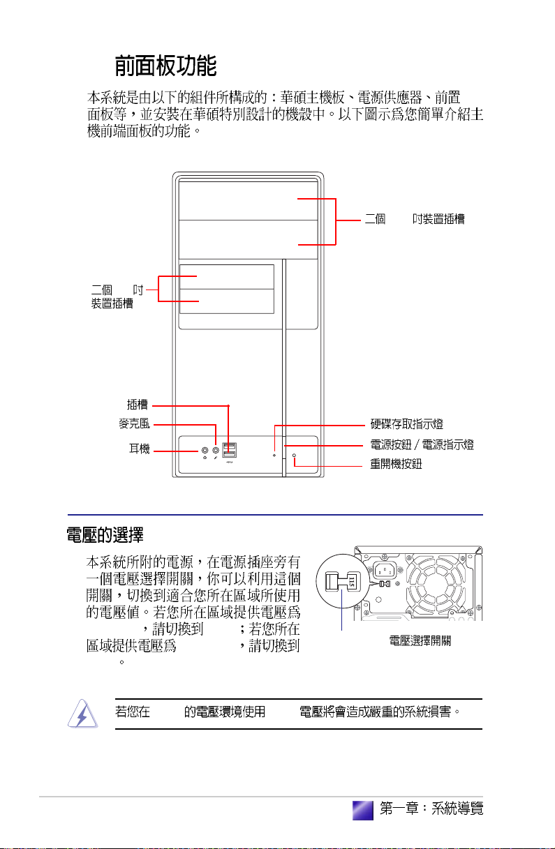
100-127V 115V
200-240V
230V
230V 115V
115V/ 230V
Page 13
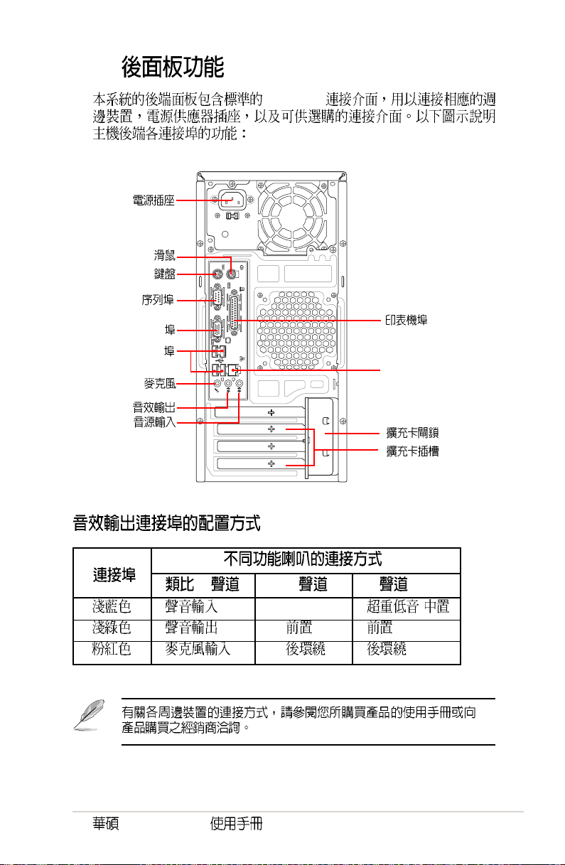
1.4
PC99 I/O
PS/2
PS/2
VGA
USB
RJ-45 LAN
2 4 6
- /
Vintage2-AE1
1-5
Page 14
1.5
1. Introduction
PS/2 USB PS/2
PS/2 USB
USB
9
1.
2. 5.25
3.
4.
5.
6. CPU
7.
PS/2KBMS
T: Mouse
B: Keyboard
COM1
VGA
USB12
LAN_USB34
Top:Line In
Center:Line Out
Below:Mic In
5
KBPWR
PARALLEL PORT
8
USBPW12
ATX12V
USBPW34
10
RTL8201CL
PCIEX1
11
CR2032 3V
Lithium Cell
A8V-MQ
CMOS Power
PCI1
SB_PWR
CLRTC
ALC653
AUX CD
PCI2
SPDIF
FP_AUDIO
K8M800
AGP
USBPW56
USBPW78
CPU_FAN
6
Socket 939
VIA
12
USB56
7
DDR DIMM_B1 (64 bit,184-pin module)
DDR DIMM_A1 (64 bit,184-pin module)
PRI_IDE
CHA_FAN
BUZZER
SATA2
SATA1
VIA
SATA4
VT8251
SATA3
CHASSIS
PANEL
USB78
EATXPWR
BIOS
Flash
ROM
I/O
Super
FLOPPY
SEC_IDE
13
2
3
4
1
8.
9.
10. AGP
11. PCI Express x1
12. PCI
13. SATA
1-6
Page 15

step-by-step
Page 16
2.1
2.2
2.3 CPU
2.3.1
2.3.2
2.3.3 CPU
2.4
2.4.1
2.4.2
2.4.3
2.4.4
2.5
2.5.1
2.5.2
2.5.3
2.5.4 PCI
2.5.5 PCI Express x1
2.5.6 AGP 8X
2.5.7 ( )
2.6
2.6.1
2.6.2
2.6.3
2.7
2.8
2.9
...................................................................................
......................................................................................
...................................................................................
.....................................................................................
.....................................................................................
.............................................................................
2-3
...............................................................
...................................................................
..................................................................
....................................................................
..................................................................
..........................................................................
................................................................
................................................................
........................................................................
................................................
....................................
........................................................
......................................
.................................................
........................................................
........................................................................
........................................................................
........................................................................
.....................................................................
.............................................................
2-4
2-5
2-5
2-5
2-6
2-8
2-8
2-8
2-11
2-11
2-12
2-12
2-12
2-13
2-14
2-14
2-14
2-15
2-16
2-16
2-17
2-17
2-18
2-19
2-19
Page 17
2.1
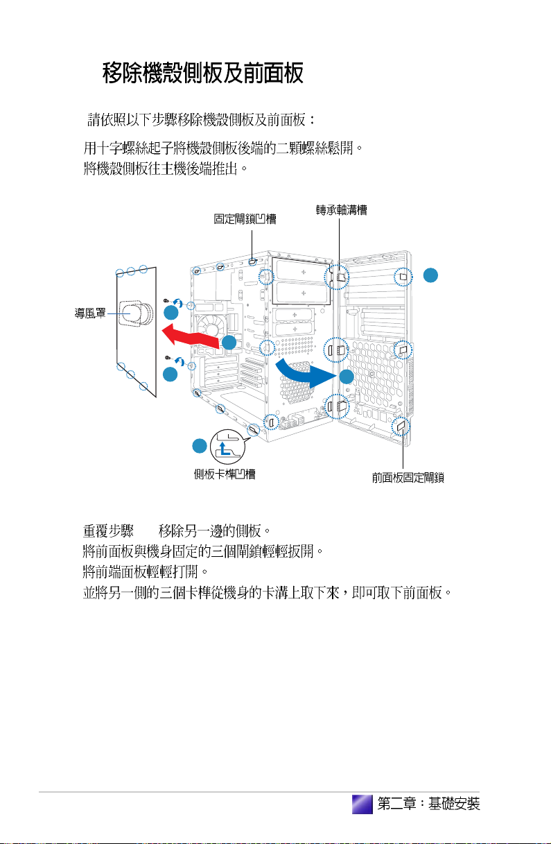
1.
2.
3.
4.
5.
/
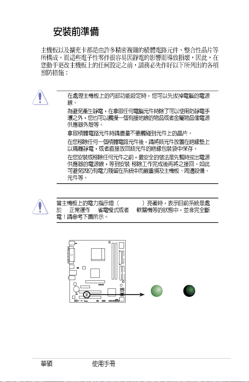
SB_PWR
(1) (2) (3)
Onboard LED
Vintage2-AE1
ON
Standby
Power
SB_PWR
OFF
Powered
Off
®
2-3
Page 18
2.2
1.
2.
3
1
2
3. 1-2
4.
5.
6.
1
2
4
2-4
Page 19
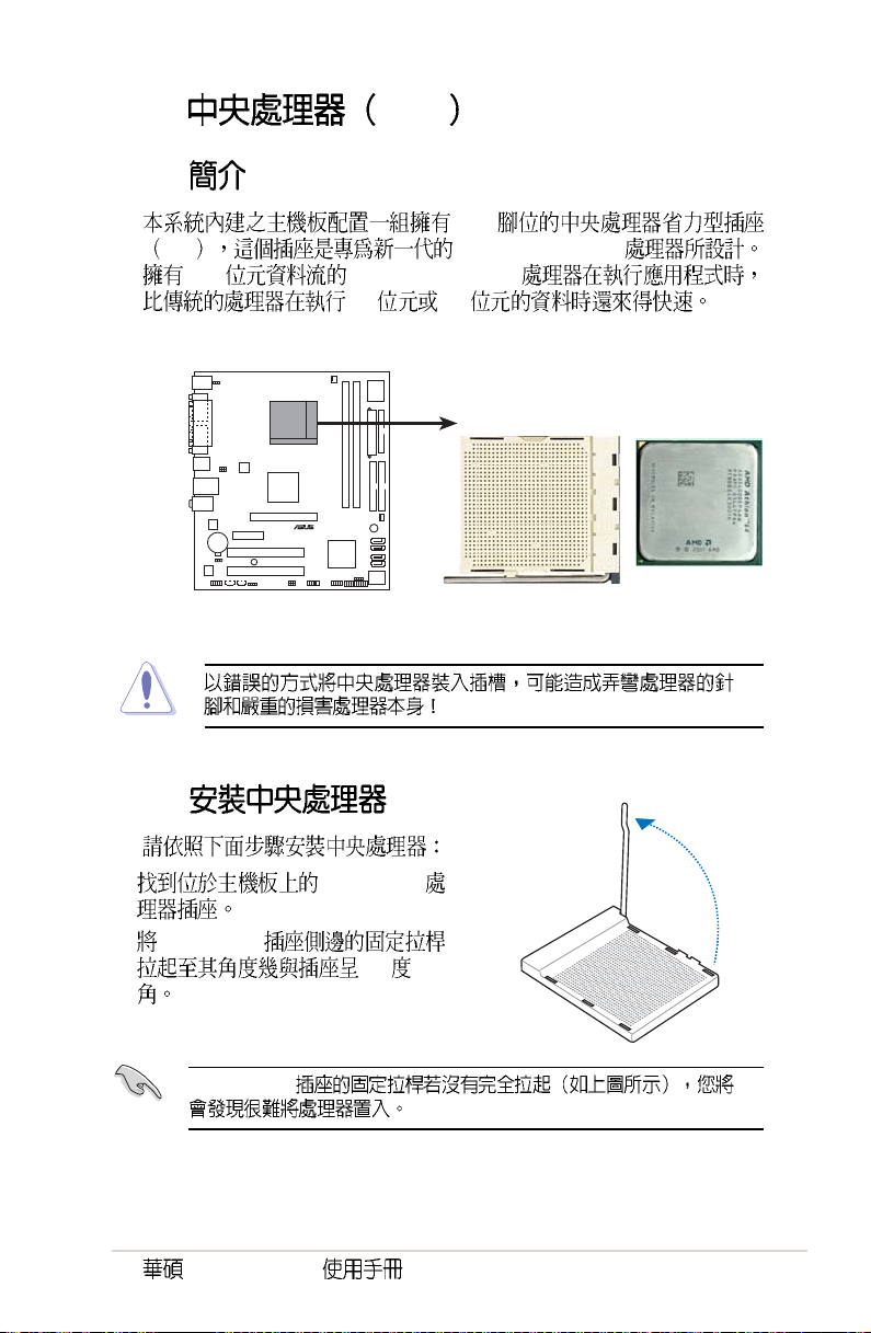
2.3 CPU
2.3.1
939
ZIF AMD® AthlonTM 64
128 AMD® AthlonTM 64
32 64
®
CPU Socket 939
2.3.2
1. Socket-939
2. Socket-939
90
Socket-939
Vintage2-AE1
2-5
Page 20
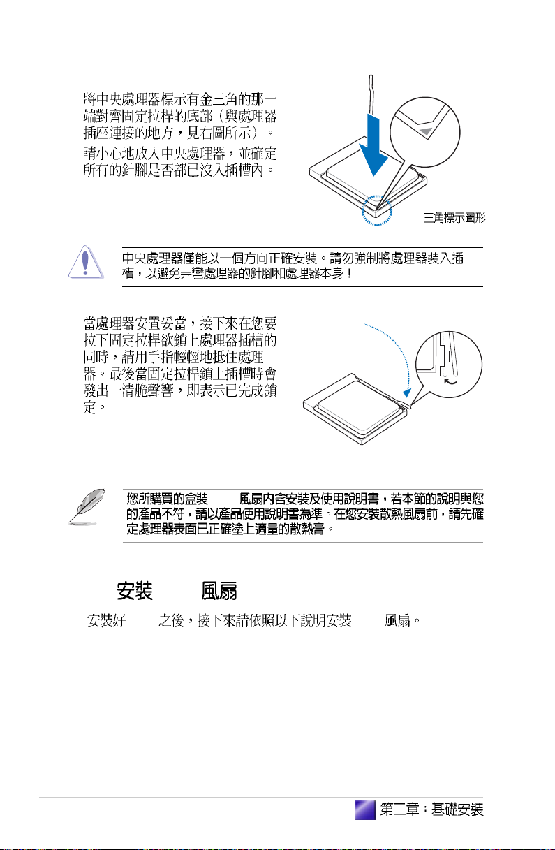
3.
4.
5.
CPU
2.3.3 CPU
CPU CPU
2-6
Page 21
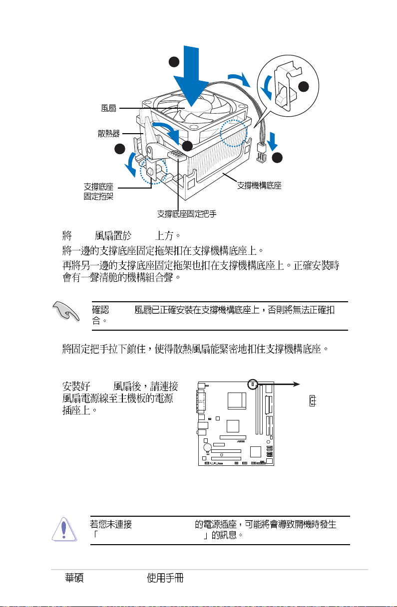
CPU
CPU
3
1. CPU CPU
2.
3.
CPU
4.
1
2
4
5
5. CPU
Hardware monitoring errors
Vintage2-AE1
CPU_FAN
®
CPU fan connector
CPU_FAN
GND
+12V
Rotation
2-7
Page 22
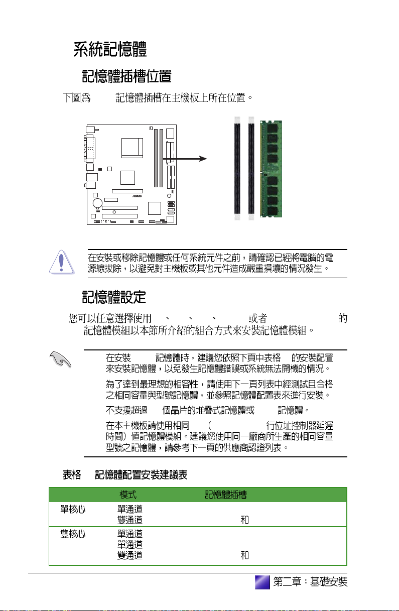
2.4
2.4.1
DDR
®
2.4.2
CPU
184-pin DDR DIMM sockets
DIMM_A1
DIMM_B1
64 128 256 512MB 1GB DDR DIMM
1. DDR 1
2.
3. 18 DDR
4. CL CAS-Latency
1
DIMM_B1
DIMM_A1 DIMM_B1
DIMM_A1
DIMM_B1
DIMM_A1 DIMM_B1
2-8
Page 23
2 DDR400 QVL
SizeSize
VendorVendor
Vendor
VendorVendor
Model Model
Model
Model Model
Size
SizeSize
256 MB KINGSTON KVR400X72C3A/256 Mosel SS V58C2256804SAT5(ECC) – •
512 MB KINGSTON KVR400X72C3A/512 Mosel DS V58C2256804SAT5(ECC) –
512 MB KINGSTON KHX3200A/512 – DS N/A – • •
1024 MB KINGSTON KHX3200ULK2/1G – DS N/A 2
256 MB KINGSTON KVR400X64C3A/256 – SS D3208DL3T-5A – • •
256 MB KINGSTON KVR400X64C3A/256 – SS A2S56D30BTP511ALM09 – •
512 MB KINGSTON KVR400X64C3A/512 – DS V58C2256804SAT5 – •
512 MB KINGSTON KVR400X64C3A/512 – SS HY5DU12822BT-D43 – • •
1024 MB KINGSTON KVR400X64C3A/1G – DS HYB25D512800BE-5B – • •
256 MB SAMSUNG M381L3223ETM-CCC SAMSUNG SS K4H560838E-TCCC(ECC) 3ECC
512 MB SAMSUNG M381L6423ETM-CCC SAMSUNG DS K4H560838E-TCCC(ECC) – • •
256 MB SAMSUNG M368L3223ETM-CCC SAMSUNG SS K4H560838E-TCCC – • •
256 MB SAMSUNG M368L3223FTN-CCC SAMSUNG SS K4H560838F-TCCC 3 • •
512 MB SAMSUNG M368L6423FTN-CCC SAMSUNG DS K4H560838F-TCCC 3 • •
512 MB SAMSUNG M368L6523BTM-CCC SAMSUNG SS K4H510838B-TCCC 3 • •
256 MB MICRON MT8VDDT3264AG-40BCB MICRON SS MT46V32M8TG-5BC – • •
512 MB MICRON MT16VDDT6464AG-40BCB MICRON DS MT46V32M8TG-5BC – • •
256 MB Infineon HYS64D32300HU-5-C Infineon SS HYB25D256800CE-5C 3 • •
512 MB Infineon HYS64D64320HU-5-C Infineon DS HYB25D256800CE-5C – • •
256 MB Infineon HYS64D32301HU-5-C Infineon SS HYB25D512160CE-5C 3 • •
512 MB Infineon HYS64D64300HU-5-C Infineon SS HYB25D512800CE-5C 3 • •
1024 MB Infineon HYS64D128320HU-5-C Infineon DS HYB25D512800CE-5B 3 • •
256 MB CORSAIR CMX256A-3200C2PT Winbond SS W942508BH-5 2 • •
512 MB CORSAIR CMX512-3200C2 Winbond DS – 2 • •
512 MB CORSAIR VS512MB400 VALUE seLecTDS VS32M8-5 2.5 • •
1024 MB CORSAIR TWINX2048-3200C2 – DS – 3 • •
256 MB Hynix HYMD232646D8J-D43 Hynix SS HY5DU56822DT-D43 3 • •
512 MB Hynix HYMD264646D8J-D43 Hynix DS HY5DU56822DT-D43 3 • •
256 MB TwinMOS M2G9I08AIATT9F081AADT TwinMOS SS TMD7608F8E50D 2.5
512 MB TwinMOS M2G9J16AJATT9F081AADT TwinMOS DS TMD7608F8E50D 2.5
256 MB TwinMOS M2G9I08A8ATT9F081AADT TwinMOS SS TMD7608F8E50D 2.5
512 MB TwinMOS M2G9J16A8ATT9F081AADT TwinMOS DS TMD7608F8E50D 2.5
256 MB Transcend TS32MLD64V4F3 SAMSUNG SS K4H560838F-TCCC 3
512 MB Transcend TS64MLD64V4F3 SAMSUNG DS K4H560838F-TCCC 3
1024 MB Transcend TS128MLD64V4J SAMSUNG DS K4H510838B-TCCC 3
256 MB Apacer 77.10636.33G Infineon SS HYB25D256800CE-5C 3
512 MB Apacer 77.10736.33G Infineon DS HYB25D256800CE-5C 3
256 MB Apacer 77.10639.60G ProMOS SS V58C2256804SCT5B 2.5
512 MB Apacer 77.10739.60G ProMOS DS V58C2256804SCT5B 2.5
256 MB A DATA MDOSS6F3G31Y0K1E0Z SAMSUNG SS K4H560838E-TCCC 3
512 MB A DATA MDOSS6F3H41Y0N1E0Z SAMSUNG DS K4H560838F-TCCC 3
256 MB A DATA MDOHY6F3G31Y0N1E0Z Hynix SS HY5DU56822CT-D43 3
512 MB A DATA MDOHY6F3H41Y0N1E0Z Hynix DS HY5DU56822CT-D43 3
256 MB A DATA MDOAD5F3G31Y0D1E02 – SS ADD8608A8A-5B 2.5
512 MB A DATA MDOAD5F3H41Y0D1E02 – DS ADD8608A8A-5B 2.5
256 MB Winbond W9425GCDB-5 Winbond SS W942508CH-5 3
512 MB Winbond W9451GCDB-5 Winbond DS W942508CH-5 –
256 MB PSC AL5D8B53T-5B1K PSC SS A2S56D30BTP 2.5
512 MB PSC AL6D8B53T-5B1K PSC DS A2S56D30BTP 2.5
256 MB KINGMAX MPXB62D-38KT3R – SS KDL388P4LA-50 –
512 MB KINGMAX MPXC22D-38KT3R – DS KDL388P4LA-50 –
BrandBrand
Brand
BrandBrand
Side(s)Side(s)
Side(s)
Side(s)Side(s)
ComponentComponent
Component
ComponentComponent
CL CL
DIMM supportDIMM support
CL
DIMM support
CL CL
DIMM supportDIMM support
AA
A
AA
BB
B
BB
Vintage2-AE1
2-9
Page 24
SizeSize
VendorVendor
Size
Vendor
SizeSize
VendorVendor
256 MB NANYA NT256D64S88C0G-5T – SS NT5DS32M8CT-5T 3
512 MB NANYA NT512D64S8HC0G-5T – DS NT5DS32M8CT-5T 3
256 MB NANYA NT256D64SH4B0G-5T – SS NT5DS32M16BT-5T 3
512 MB NANYA NT512D64S88B0G-5T – DS NT5DS64M8BT-5T 3
1024 MB NANYA NT1GD64S8HB0G-5T – DS NT5DS64M8BT-5T –
256 MB CENTURY DXV6S8SSCCE3K27E SAMSUNG SS K4H560838E-TCCC –
512 MB CENTURY DXV2S8SSCCE3K27E SAMSUNG DS K4H560838E-TCCC –
256 MB CENTURY DXV6S8EL5BM3T27C – SS DD2508AMTA –
512 MB CENTURY DXV2S8EL5BM3T27C – DS DD2508AMTA –
256 MB CENTURY DXV6S8EL5B – SS DD2508AMTA –
256 MB CENTURY DXV6S8HXD43B – SS HY5DU56822BT-D43 –
256 MB CENTURY DXV6S8HXD43D – SS HY5DU56822DT-D43 –
512 MB CENTURY DXV2S8EL5B – D S DD2508AMTA –
512 MB CENTURY DXV2S8HXD43B – DS HY5DU56822BT-D43 –
512 MB CENTURY DXV2S8HXD43D – DS HY5DU56822DT-D43 –
256 MB CENTURY DXV6S8EL5B/HP – SS DD2508AKTA-5B-E –
512 MB CENTURY DXV2S8EL5B/HP – DS DD2508AKTA-5B-E –
256 MB KINGSTON KVR400X72C3A/256 Mosel SS V58C2256804SAT5(ECC) – •
256 MB CENTURY DXV6S8MC5B – SS MT46V32M8TG-5BG –
512 MB CENTURY DXV2S8MC5B – DS MT46V32M8TG-5BG –
256 MB elixir M2U25664DS88C3G-5T elixir SS N2DS25680CT-5T 3
512 MB elixir M2U51264DS8HC1G-5T elixir DS N2DS25680CT-5T 3
256 MB Kreton – VT SS VT3225804T-5 –
512 MB Kreton – VT DS VT3225804T-5 –
256 MB Veritech VU256FLTM25C VT SS VT56DD32M8PC-5 3
512 MB Veritech VU512FLTM25C VT DS VT56DD32M8PC-5 3
256 MB Pmi MD44256VIT3208GMHA01 MOSEL SS V58C2256804SAT5B 2.5
512 MB Pmi MD44512VIT3208GATA03 MOSEL DS V58C2256804SAT5B 2.5
256 MB ProMOS V826632K24SCTG-D0 – SS V58C2256804SCT5B 2.5
512 MB ProMOS V826664K24SCTG-D0 – DS V58C2256804SCT5B 2.5
256 MB Deutron AL5D8C53T-5B1T PSC SS A2S56D30CTP 2.5
512 MB Deutron AL6D8C53T-5B1T PSC DS A2S56D30CTP 2.5
256 MB GEIL GL5123200DC – SS GL3LC32G88TG-35 –
512 MB GEIL GL1GB3200DC – DS GL3LC32G88TG-35 –
256 MB GEIL GLX2563200UP – SS GL3LC32G88TG-5A –
256 MB GEIL GD3200-512DC – SS WLCSP Package –
256 MB crucial BL3264Z402.8TG Ballistix SS – 2
512 MB crucial BL6464Z402.16TG Ballistix DS – 2
256 MB Novax 96M425653CE-40TB6 CEON SS C2S56D30TP-5 2.5
512 MB Novax 96M451253CE-40TB6 CEON DS C2S56D30TP-5 2.5
256 MB Aeneon AED560UD00-500C88X Aeneon SS AED83T500 3
256 MB V-DATA MDYVD6F4G2880B1E0H – SS VDD9616A8A-5C –
Model Model
Model
Model Model
BrandBrand
Brand
BrandBrand
Side(s)Side(s)
Side(s)
Side(s)Side(s)
ComponentComponent
Component
ComponentComponent
CL CL
DIMM supportDIMM support
CL
DIMM support
CL CL
DIMM supportDIMM support
AA
BB
A
B
AA
BB
2-10
A -
B -
SS -
DS - CL - CAS Latency
http://
tw.asus.com
Page 25
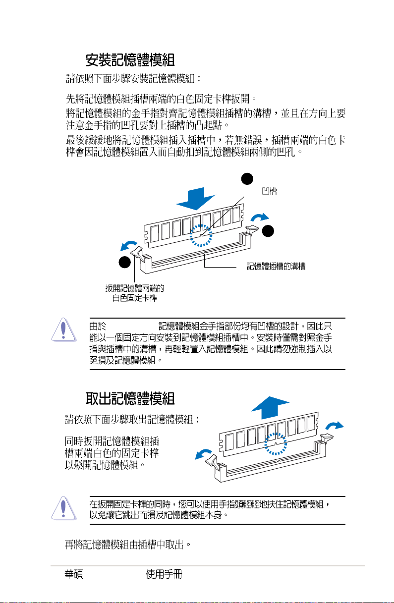
2.4.3
1.
2.
3.
2
DIMM
1
1
DDR DIMM
2.4.4
1.
2.
Vintage2-AE1
2-11
Page 26
2.5
2.5.1
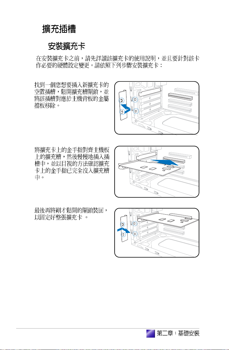
1.
2.
2-12
3.
Page 27
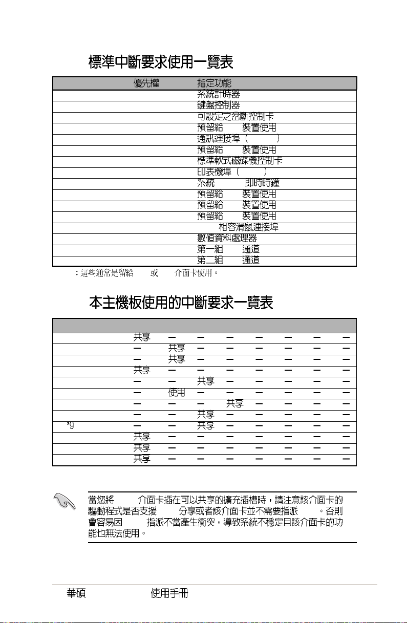
2.5.2
IRQ
01
12
2 N/A
3* 11 PCI
4* 12 COM 1
5* 13 PCI
614
7* 15 LPT 1
83 CMOS/
9* 4 PCI
10* 5 PCI
11* 6 PCI
12* 7 PS/2
13 8
14* 9 IDE
15* 10 IDE
* ISA PCI
2.5.3
ABCDEFGH
PCI slot 1
PCI slot 2
IDE (0, 0f, 0)
USB controller 1
USB controller 2
USB controller 3
USB controller 4
USB 2.0 controller
AC 7
Ethernet
AGP
PCIE x1
PCI
IRQ
Vintage2-AE1
IRQ IRQ
2-13
Page 28
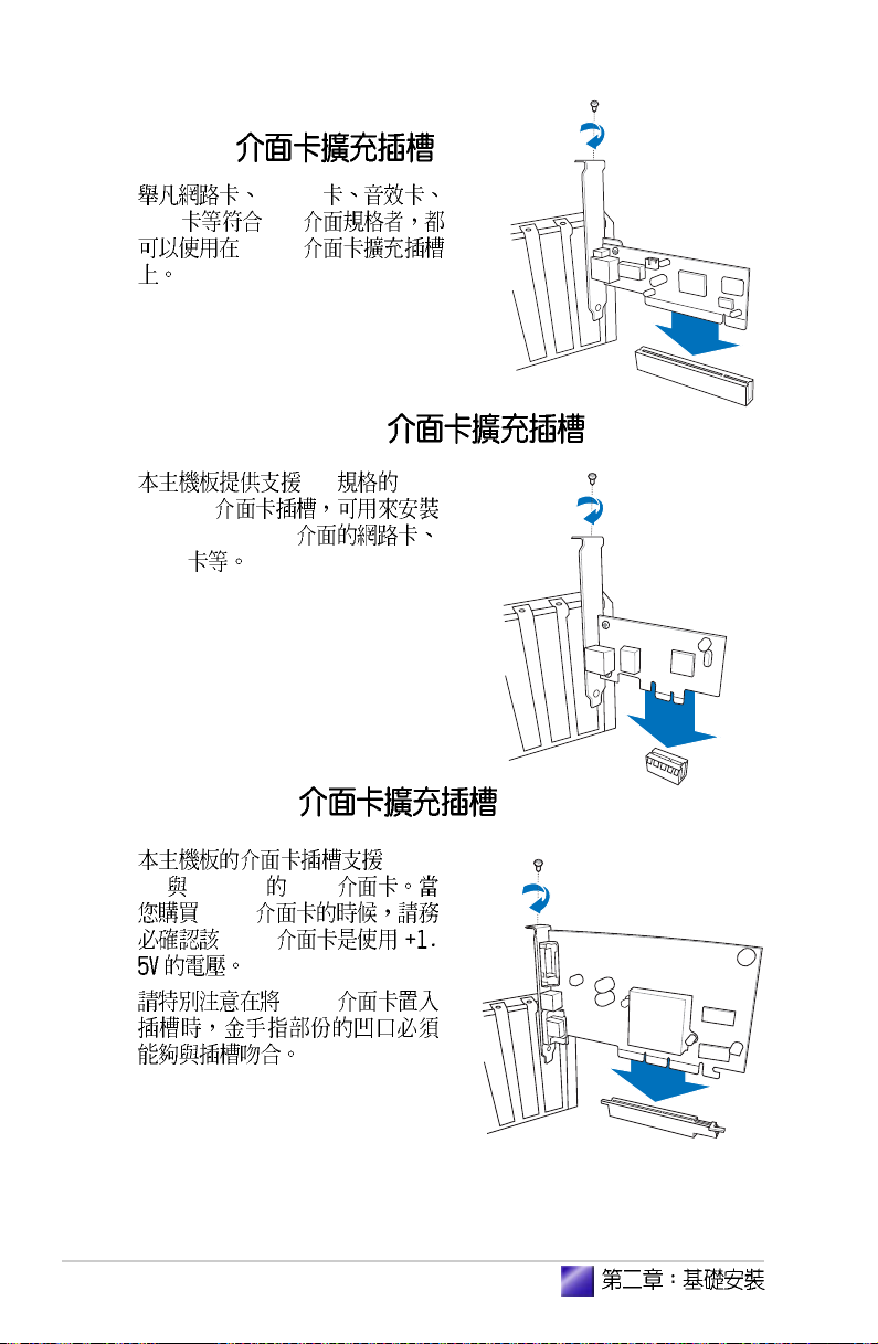
2.5.4 PCI
SCSI
USB PCI
PCI
2.5.5 PCI Express x1
x1 PCI
Express
PCI Express x1
SCSI
2.5.6 AGP 8X
8X AGP 4X AGP
AGP
2-14
AGP
AGP
AGP
Page 29
2.5.7
4-pin
USB
1. 2.5.1 1 ~ 3
2. CON1 4-pin
USB 4-9 USB
3.
( )
3.4.5
Vintage2-AE1
2-15
Page 30
2.6
2.6.1
3
1.
2.
3.
4. IDE (A)
- -
Serial ATA (B)
IDE
3
2
2-16
A B
SATA
IDE
Serial ATA
SATA Windows XP Windows 2000
Windows XP Windows 2000 F6
Page 31

2.6.2
3
3
2
CD-ROM/CD-RW/DVD-ROM/DVD-RW
2
3
1.
2. 5.25
3.
4. IDE
2.6.3
3
IDE
1.
2.
3.
4.
Vintage2-AE1
2-17
Page 32

2.7
Reset
PANEL 4-12
Reset
PLED
PLED+
®
System panel connector
PANEL
IDE_LED-
IDE_LED+
IDE_LED
* Requires an ATX power supply.
PLED 2-pin Vintage2
PLED-
SPEAKER
Ground
Speaker
Ground
+5V
PWR
Reset
Ground
Ground
RESET
PWRSW
*
2-18
Page 33

2.8
1.
2.
3.
4. 3.5
2.9
1.
2.
3.
4.
5.
6.
7. 4 ~ 6
Vintage2-AE1
5
4
5
3
1
2
2-19
Page 34

2-20
Page 35

Page 36

3.1
3.2
3.3
3.3.1
3.3.2 Drivers Menu
3.3.3 Utilities Menu
3.3.4 Make Disk Menu
3.3.5
3.3.6
3.4 ASUS PC Probe II
3.4.1
3.5 Cool n QuietTM
...............................................................................
.......................................................................................
...................................................
......................................................................
.................................................................
..........................................................
....................................................
3-3
3-3
3-4
.........................................
..............................
.............................
..................................
.....................................
3-4
3-4
3-5
3-7
3-7
3-8
3-9
3-9
3-16
Page 37

3.1
3.2
Windows 2000/XP
Vintage2-AE1
3-3
Page 38

3.3
3.3.1
http://tw.asus.com
3.3.2 Drivers Menu
3-4
Page 39

AMD Cool n Quiet
AMD Cool n Quiet
VIA
VIA
VIA S3G
VIA S3G
Realtek
Realtek
VIA Rhine
VIA Rhine
Realtek RTL8187
Realtek RTL8187
USB 2.0
USB 2.0 USB 1.1 USB 2.0
Windows XP Windows
XP Service Pack 1 USB 2.0
3.3.3 Utilities Menu
Vintage2-AE1
3-5
Page 40

II ASUS PC Probe II
ASUS Live Update
BIOS
MyLogoTM
ASUS Cool n Quiet
ASUS Cool n Quiet
Adobe Acrobat Reader
Adobe Acrobat Reader PDF Portable
Document Format
Microsoft DirectX 9.0
DirectX 9.0
3-6
Page 41

3.3.4 Make Disk Menu
Make Disk RAID
VIA RAID
VIA RAID
3.3.5
PDF
Adobe Acrobat Reader
RTL8187 Wireless LAN
RTL8187 Wireless LAN
Vintage2-AE1
3-7
Page 42

3.3.6
3-8
Page 43

3.4 ASUS PC Probe II
CPU
3.4.1
ASUS PC Probe II
Peripheral Component Interconnect
Windows Management Instrumentation
Vintage2-AE1
CPU
3-9
Page 44

PC PROBE II
Preferences
( ) ( )
3-10
Page 45

Scheme
CPU
Enable Monitoring Panel
OK
Config
Vintage2-AE1
3-11
Page 46

WMI
WMI (Windows Management Instrumentation)
Windows
WMI Information (+)
3-12
Page 47

DMI
PCI
DMI (Desktop Management Interface)
DMI Information (+)
PCI (Peripheral Component Interconnect)
PCI PCI Information (+)
Vintage2-AE1
3-13
Page 48

Usage
Usage CPU
Usage
CPU usage
CPU CPU CPU
Hyper-Threading*
3-14
* Intel CPU
Page 49

Hard Disk
Memory
Vintage2-AE1
3-15
Page 50

3.5 Cool n QuietTM
Cool n Quiet!
AMD Cool n Quiet! AMD Athlon XP
AMD Cool n QuietTM support CD
Cool n QuietTM CPU
CPU
Cool n Quiet!
Cool n Quiet!
1. <Del> BIOS
2. Advanced Cool n Quiet Enabled
5.4
3. Power ACPI 2.0 Support Yes
5.5
4. BIOS
5.
Windows 2000/XP
1. Windows 2000/XP
2.
3. ...
4.
5.
3-16
Page 51

3.3.3 Cool n QuietTM
Cool n QuietTM
Windows 98SE/ME/2000 OS
1.
2. > ASUS > Cool & Quiet > Cool & Quiet.
Windows XP OS
1.
2. > ASUS > Cool & Quiet > Cool & Quiet.
Cool n Quiet! CPU
(X) (
Vintage2-AE1
3-17
Page 52

3-18
Page 53

Jumper
BIOS
<Del> BIOS
( )
Page 54

4.1
4.2
4.3
4.4
...............................................................................................
...............................................................................
...................................................................................
...............................................................
4.4.1
4.4.2
.................................................................
.............................................................
4-3
4-3
4-4
4-6
4-6
4-7
Page 55

4.1
4.2
21.8cm (8.6in)
PS/2KBMS
T: Mouse
B: Keyboard
COM1
VGA
USB12
LAN_USB34
Top:Line In
Center:Line Out
Below:Mic In
ALC653
FP_AUDIO
KBPWR
PARALLEL PORT
USBPW12
USBPW34
RTL8201CL
CR2032 3V
Lithium Cell
CMOS Power
CLRTC
ATX12V
PCIEX1
AUX CD
PCI1
SB_PWR
PCI2
SPDIF
VIA
K8M800
AGP
USBPW56
USBPW78
CPU_FAN
Socket 939
®
USB56
I/O
Super
EATXPWR
DDR DIMM_B1 (64 bit,184-pin module)
DDR DIMM_A1 (64 bit,184-pin module)
PRI_IDE
CHA_FAN
BUZZER
SATA2
PANEL
CHASSIS
SATA1
SATA4
SATA3
BIOS
Flash
ROM
VIA
VT8251
USB78
FLOPPY
24.5cm (9.6in)
SEC_IDE
Vintage2-AE1
4-3
Page 56

4.3
1. CMOS CLRTC
CMOS
CMOS
1
2 CLRTC [1-2] [2-3]
CMOS [1-2]
3
4 Del BIOS
BIOS
CMOS
4-4
®
Clear RTC RAM
CLRTC
12 23
Normal Clear CMOS
(Default)
CMOS C.P.R. CPU
BIOS
Page 57

2. USB 3-pin USBPWR12, USBPWR34,
USBPWR56, USBPWR78
+5V USB S1
+5VSB S3 S4
+5V USBPWR12 USBPWR34
USB USBPWR56
USB
USBPW12
USBPW34
21
2
3
®
USB device wake-up
1. USB +5VSB
500mA/+5VSB
2.
+5VSB
3. 3-pin KBPWR1
KBPWR1 [2-3]
+5VSB
1A/+5VSB BIOS
[1-2] +5V
+5V
(Default)
USBPW56
USBPW78
21
+5V
(Default)
KBPWR
2312
+5V +5VSB
(Default)
+5VSB
2
+5VSB
3
Keyboard power setting
Vintage2-AE1
®
4-5
Page 58

4.4
4.4.1
1
11 1 0
2
9 8
3
4
5
6
7
1. PS/2 PS/2
2.
3. RJ-45 LAN
Local Area Network
4.
5.
6.
4-6
Page 59

7. USB 2.0 3 4 USB
USB 2.0
8. USB 2.0 1 2 USB
USB 2.0
9. VGA VGA VGA
10. 9-pin COM1
11.PS/2 PS/2
4.4.2
1. IDE 40-1 pin PRI_IDE, SEC_IDE
IDE
IDE CD-ROM ZIP MO
Primary
Secondary Slave
UltraATA133 IDE
Master UltraATA133 IDE
1. IDE
Master
Slave
2. IDE
UltraDMA
3. UltraATA
®
IDE connectors
Vintage2-AE1
PIN 1
NOTE: Orient the red markings
(usually zigzag) on the IDE
ribbon cable to PIN 1.
SEC_IDE
PRI_IDE
PIN 1
Pin 1
4-7
Page 60

2. 24-pin ATXPWR, 4-pin ATX12V
ATX 12V
24 ATXPWR
+12V
ATX 12V +12V 8
+5VSB 1
230
300
ATX12V
GND
+12V DC
®
GND
+12V DC
ATX power connectors
3. 34-1 pin FLOPPY
FLOPPY
NOTE: Orient the red markings on
the floppy ribbon cable to PIN 1.
®
PIN 1
+3 Volts
-12 Volts
Ground
PSON#
Ground
Ground
Ground
-5 Volts
+5 Volts
+5 Volts
+5 Volts
Ground
Pin 1
EATXPWR
+3 Volts
+3 Volts
Ground
+5 Volts
Ground
+5 Volts
Ground
Power OK
+5V Standby
+12 Volts
+12 Volts
+3 Volts
4-8
Floppy disk drive connector
Page 61

4. 4-pin CD, AUX
MPEG
®
Internal audio connectors
AUX
(White)
Ground
Ground
Left Audio Channel
Right Audio Channel
(Black)
Left Audio Channel
5. / 3-pin CPU_FAN,
CHA_FAN
350 740 8.88 1 2.22
26.64 /+12
+12V
GND
CD
Ground
Ground
Right Audio Channel
Fan connectors
Vintage2-AE1
CPU_FAN
GND
+12V
Rotation
®
CHA_FAN
GND
+12V
Rotation
4-9
Page 62

6. USB 10-1 pin USB56, USB78
USB
USB USB
USB USB 2.0
USB 2.0 USB
®
USB+5V
USB_P8-
USB78
1
USB 2.0 connectors
USB+5V
USB_P7-
1.
2. USB 2.0 USB 2.0
USB_P8+
GND
NC
GND
USB_P7+
USB56
USB+5V
1
USB+5V
USB_P6-
USB_P6+
GND
GND
USB_P5-
USB_P5+
NC
7. Serial ATA RAID 7-pin SATA1, SATA2
Serial ATA Serial ATA
150MB 133MB
Parallel ATA UltraATA 133
SATA 2
GND
GND
GND
RSATA_TXP2
RSATA_TXN2
RSATA_RXP2
RSATA_RXN2
SATA 1
GND
GND
GND
RSATA_TXP1
RSATA_TXN1
RSATA_RXP1
RSATA_RXN1
®
SATA connectors
4-10
SATA 4
GND
RSATA_TXP4
RSATA_TXN4
SATA 3
GND
RSATA_TXP3
RSATA_TXN3
GND
GND
RSATA_RXP4
RSATA_RXN4
GND
GND
RSATA_RXP3
RSATA_RXN3
Page 63

8. 10-1 FP_AUDIO
Intel
/
LINE OUT_R/BLINE_OUT_R
LINE OUT_L/BLINE_OUT_L
®
FP_AUDIO
Front audio connector
9. 4-1 pin CHASSIS
CHASIS Chassis
Signal GND
Chassis Signal GND
®
CHASSIS
+5VSB_MB
Chassis Signal
AGND
MIC2
GND
+5VA
MICPWR
BLINE_OUT_L
BLINE_OUT_R
NC
Line out_L
Line out_R
Chassis intrusion connector
Vintage2-AE1
(Default)
4-11
Page 64

10. 10-1 pin PANEL
PLED
PLED+
®
System panel connector
•
•
4-pin SPEAKER
•
PANEL
IDE_LED+
IDE_LED
*
Requires an ATX power supply.
3-1 pin PLED
2-pin RESET
PLED-
IDE_LED-
SPEAKER
+5V
PWR
Ground
PWRSW
Reset
ATX / 2-pin PWRSW
•
BIOS
Ground
Speaker
Ground
Reset
Ground
RESET
4-12
IDE 2-pin IDE_LED
•
IDE_LED IDE
IDE
Page 65

BIOS
( )
BIOS
BIOS
BIOS
<Del> BIOS
Page 66

5.1 BIOS
5.1.1
5.1.2 AFUDOS BIOS
5.1.3 AFUDOS BIOS
5.1.4 EZ Flash BIOS
5.1.5 CrashFree BIOS 2 BIOS
5.1.6
5.2 BIOS
5.2.1 BIOS
5.3 Main Menu
5.3.1 System Time [XX:XX:XX]
5.3.2 System Date [XX/XX/XXXX]
5.3.3 Legacy Diskette A [1.44M, 3.5 in.]
5.3.4 IDE
5.3.5 Onboard PCI S-ATA Controller [RAID by Rom]
5.3.6 System Information
5.4 Advanced menu
5.4.1 JumperFree JumperFree Configuration
5.4.2 USB USB Configuration
5.4.3 CPU Configuration
5.4.4 Chipset
5.4.5 OnBoard Devices Configuration
5.4.6 PCI PCI PnP
5.5 Power menu
5.5.1 Suspend Mode [Auto]
5.5.2 Repost Video on S3 Resume [No]
5.5.3 ACPI 2.0 Support [No]
5.5.4 ACPI APIC Support [Enabled]
5.5.5 APM Configuration
5.5.6 Hardware Monitor
5.6 Boot menu
5.6.1 Boot Device Priority
5.6.2 Boot Settings Configuration
5.6.3 Security
5.7 BIOS Exit menu
......................................................................
...........................................................................
....................................................................
........................................................
..................................................................
.........................................
.................................
..................................
..........................................................
...............................................................
...............................................
..........................................
...................................
....................................
...................................................
................................
.......................................................
.......................................
.........................................................
........................................................
.....................................
......................................................
..........................................
..............................
............................................................
..................................................
..................................................
...................
.............
.............
............................
........
....................
..........................
...............
5-3
5-3
5-4
5-5
5-6
5-7
5-9
5-12
5-13
5-15
5-15
5-15
5-15
5-16
5-17
5-17
5-18
5-18
5-19
5-20
5-20
5-26
5-27
5-28
5-28
5-28
5-28
5-28
5-29
5-30
5-32
5-32
5-32
5-34
5-37
5-2
BIOS
Page 67

5.1 BIOS
BIOS
1. AFUDOS DOS BIOS
2. ASUS EZ Flash Power-On Self
Test POST BIOS
3. ASUS CrashFree BIOS 2 BIOS
BIOS
4. ASUS Update Windows BIOS
1. BIOS
BIOS AFUDOS
BIOS
2. BIOS
BIOS
3. http://tw.asus.com
BIOS
5.1.1
1.
DOS
1.44MB DOS
format A:/S Enter
Windows XP
a. 1.44MB
b. Windows
c. 3 1/2
d. File Format Format 3 1/
2 Floppy Disk
c. Create a MS-DOS startup disk
Vintage2-AE1
5-3
Page 68

Windows 2000
a. 1.44MB
b. Windows 2000
c. Run
d. D:\bootdisk\makeboot a:
D
e. Enter
2. BIOS
5.1.2 AFUDOS BIOS
DOS AFUDOS.EXE BIOS
1. tw.asus.com BIOS
BIOS
BIOS
2. AFUDOS.EXE
BIOS
3.
4. DOS
afudos /i[filename]
filename
BIOS
5. Enter
5-4
BIOS
A:\>afudos /iA8VMQ.rom
AMI Firmware Update Utility - Version 1.10
Copyright (C) 2002 American Megatrends, Inc. All rights reserved.
Reading file ..... done
Erasing flash .... done
Writing flash .... 0x0008CC00 (9%)
BIOS
BIOS
Page 69

DOS
A:\>afudos /iA8VMQ.rom
AMI Firmware Update Utility - Version 1.10
Copyright (C) 2002 American Megatrends, Inc. All rights reserved.
Reading file ..... done
Erasing flash .... done
Writing flash .... 0x0008CC00 (9%)
Verifying flash .. done
A:\>
6.
5.1.3 AFUDOS BIOS
AFUDOS.EXE BIOS
BIOS
1. DOS
afudos /o[filename]
filename
2. Enter
BIOS
A:\>afudos /oMYBIOS03.rom
AMI Firmware Update Utility - Version 1.10
Copyright (C) 2002 American Megatrends, Inc. All rights reserved.
Reading flash ..... 0x0008CC00 (9%)
Vintage2-AE1
5-5
Page 70

3. BIOS
600KB
A:\>afudos /oMYBIOS03.rom
AMI Firmware Update Utility - Version 1.10
Copyright (C) 2002 American Megatrends, Inc. All rights reserved.
Reading flash ..... done
A:\>
BIOS DOS
5.1.4 EZ Flash BIOS
EZ Flash BIOS
DOS EZ Flash BIOS
Power-On Self
Test POST Alt + F2 EZ Flash
EZ Flash BIOS
1. tw.asus.com BIOS
2.
3. POST Alt + F2
EZ Flash
User recovery requested. Starting BIOS recovery...
Checking for floppy...
•
Floppy not found
•
A8VMQ.ROM not found
BIOS A8VMQ.ROM
BIOS
5-6
BIOS
Page 71

4. BIOS
EZ Flash BIOS
BIOS
User recovery requested. Starting BIOS recovery...
Checking for floppy...
Floppy found!
Reading file “K8S-MV.rom”. Completed.
Start flashing...
Flashed successfully. Rebooting.
5.1.5 CrashFree BIOS 2 BIOS
CrashFree BIOS 2 BIOS
BIOS BIOS
1. BIOS
BIOS
2. BIOS
BIOS 5.1.1
BIOS
1.
2. BIOS
Bad BIOS checksum. Starting BIOS recovery...
Checking for floppy...
3. BIOS
BIOS A8VMQ.ROM
Vintage2-AE1
BIOS
5-7
Page 72

Bad BIOS checksum. Starting BIOS recovery...
Checking for floppy...
Floppy found!
Reading file “K8S-MV.rom”. Completed.
Start flashing...
BIOS
4.
BIOS
1.
2. BIOS
Bad BIOS checksum. Starting BIOS recovery...
Checking for floppy...
3.
BIOS
4. BIOS
5-8
Bad BIOS checksum. Starting BIOS recovery...
Checking for floppy...
Floppy not found!
Checking for CD-ROM...
CD-ROM found.
Reading file “K8S-MV.rom”. Completed.
Start flashing...
BIOS
BIOS BIOS
http://tw.asus.com BIOS
BIOS
Page 73

5.1.6
Windows
BIOS
1. BIOS
2. BIOS
3. BIOS BIOS
4. BIOS
5. BIOS
ISP
1.
2. VX.XX.
XX
3.
Vintage2-AE1
BIOS
5-9
Page 74

BIOS
BIOS
1. ASUS ASUSUpdate ASUSUpdate
2. Update
BIOS from the Internet
Next
3. FTP
Auto Select
5-10
Next
BIOS
Page 75

4. BIOS
Next
5.
BIOS
BIOS
BIOS BIOS
BIOS BIOS
1. ASUS
ASUSUpdate ASUSUpdate
2. Update BIOS
from a file Next
3. BIOS
4.
BIOS
Vintage2-AE1
5-11
Page 76

5.2 BIOS
BIOS Basic Input and Output System
BIOS
BIOS
RUN SETUP BIOS
BIOS
Flash ROM BIOS Flash
ROM
BIOS BIOS
BIOS
CMOS RAM
POST Power-On Self Test
Del Del
BIOS
BIOS
5-12
Ctrl + Alt + Del
BIOS
BIOS
BIOS
5.7 BIOS Load Setup Defaults
BIOS
http://tw.asus.com BIOS
BIOS
BIOS
Page 77

5.2.1 BIOS
System Time [10:55:25]
System Date [Thu 07/21/2005]
Legacy Diskette A [1.44M, 3.5 in]
Primary IDE Master [ST320410A]
Primary IDE Slave [ASUS CD-S520/A]
Secondary IDE Master [Not Detected]
Secondary IDE Slave [Not Detected]
Third IDE Master [Not Detected]
Third IDE Slave [Not Detected]
Fourth IDE Master [Not Detected]
Fourth IDE Slave [Not Detected]
System Information
BIOS
Main
Advanced
Power
Boot
Exit BIOS
Use [ENTER], [TAB]
or [SHIFT-TAB] to
select a field.
Use [+] or [-] to
configure system time.
Vintage2-AE1
5-13
Page 78

Advanced Power Boot
Exit
Enter
Main Advanced Power Boot Exit
System Time [10:55 :25]
System Date [Thu 07/21/2005]
Legacy Diskette A [1.44M, 3.5 in.]
Primary IDE Master [ST320410A]
Primary IDE Slave [ASUS CD-S520/A]
Secondary IDE Master[Not Detected]
Secondary IDE Slave [Not Detected]
Third IDE Master [Not Detected]
Third IDE Slave [Not Detected]
Fourth IDE Master [Not Detected]
Fourth IDE Slave [Not Detected]
System Information
v02.58 (C)Copyright 1985-2004, American Megatrends, Inc.
BIOS SETUP UTILITY
Use [ENTER], [TAB],
or [SHIFT-TAB] to
select a field.
Use [+] or [-] to
configure system
time.
Select Screen
Select Item
+- Change Field
Tab Select Field
F1 General Help
F10 Save and Exit
ESC Exit
[Enter]
Primary Graphics Adapter [AGP]
Search for MDA Resources [Yes]
AGP Mode [AGP 8X]
AGP Fast Write [Enabled]
Graphics Aperture Size [64MB]
Select Screen
Select Item
+- Change Option
F1 General Help
F10 Save and Exit
ESC Exit
5-14
PageUp/PageDown
BIOS
Page 79

5.3 Main Menu
BIOS
5.2.1 BIOS
System Time [10:55:25]
System Date [Thu 07/21/2005]
Legacy Diskette A [1.44M, 3.5 in]
Primary IDE Master [ST320410A]
Primary IDE Slave [ASUS CD-S520/A]
Secondary IDE Master [Not Detected]
Secondary IDE Slave [Not Detected]
Third IDE Master [Not Detected]
Third IDE Slave [Not Detected]
Fourth IDE Master [Not Detected]
Fourth IDE Slave [Not Detected]
System Information
Use [ENTER], [TAB]
or [SHIFT-TAB] to
select a field.
Use [+] or [-] to
configure system time.
5.3.1 System Time [XX:XX:XX]
5.3.2 System Date [XX/XX/XXXX]
5.3.3 Legacy Diskette A [1.44M, 3.5 in.]
[Disabled] [360K
5.25 in.] [1.2M 5.25 in.] [720K 3.5 in.] [1.44M 3.5 in,] [2.88M 3.5
in.]
Vintage2-AE1
5-15
Page 80

5.3.4 IDE Primary, Secondary, Third,
and Fourth IDE Master/Slave
BIOS IDE
IDE
Enter
Primary IDE Master
Device : Hard Disk
Vendor : ST320410A
Size : 20.0GB
LBA Mode : Supported
Block Mode : 16 Sectors
PIO Mode : 4
Async DMA : MultiWord DMA-2
Ultra DMA : Ultra DMA-5
SMART Monitoring: Supported
Type [Auto]
LBA/Large Mode [Auto]
Block(Multi-sector Transfer) M [Auto]
PIO Mode [Auto]
DMA Mode [Auto]
Smart Monitoring [Auto]
32Bit Data Transfer [Enabled]
Select the type
of device connected
to the system
Device Vendor Size LBA Mode Block
Mode PIO Mode Async DMA Ultra DMA SMART monitoring
BIOS
Not Detected
Type [Auto]
IDE Auto
IDE CDROM IDE
ARMD ATAPI
IDE ZIP LS-120 MO
[Not Installed] [Auto] [CDROM] [ARMD]
LBA/Large Mode [Auto]
LBA [Auto]
LBA LBA
[Disabled] [Auto]
Block (Multi-sector Transfer) [Auto]
[Auto]
[Disabled]
[Disabled] [Auto]
5-16
BIOS
Page 81

PIO Mode [Auto]
PIO [Auto] [0] [1] [2] [3] [4]
DMA Mode [Auto]
DMA [Auto] [SWDMA0] [SWDMA1] [SWDMA2]
[MWDMA0] [MWDMA1] [MWDMA2] [UDMA0] [UDMA1] [UDMA2]
[UDMA3] [UDMA4] [UDMA5]
SMART Monitoring [Auto]
Smart Monitoring, Analysis,
and Reporting Technology [Auto] [Disabled] [Enabled]
32Bit Data Transfer [Disabled]
32 [Disabled] [Enabled]
5.3.5 Onboard PCI S-ATA Controller [RAID by Rom]
PCI Serial ATA
[Disabled] [Native] [RAID by Rom]
5.3.6 System Information
BIOS
AMIBIOS
Version : 0108
Build Date : 09/14/05
Processor
Type : AMD Sempron(tm) Processor 3000+
Speed : 1800 MHz
Count : 1
System Memory
Size : 448 MB
AMIBIOS
BIOS
Processor
System Memory
Vintage2-AE1
5-17
Page 82

5.4 Advanced menu
Jumperfree Configuration
USB Configuration
CPU Configuration
Chipset
Onboard Devices Configuration
PCI PnP
5.4.1 JumperFree JumperFree
Configuration
Config System Frequency/Voltage
CPU FSB Frequency [200 MHz]
AGP/PCI Frequency (MHz) [Auto]
PCIE Frequency (MHz) [Auto]
CPU FSB Frequency [200 MHz]
CPU [200 MHz] [201
MHz] [202 MHz]... [300 MHz]
AGP/PCI Frequency (MHz) [Auto]
AGP/PCI [Auto] [66.66/33.33] [75.4/
37.7] [80/40]
PCIE Frequency (MHz) [Auto]
PCI Express [Auto] [Fixed Clock]
5-18
BIOS
Page 83

5.4.2 USB USB Configuration
USB
USB Configuration
Module Version - 2.24.0-10.4
USB Devices Enabled:
None
USB 1.1 Ports Configuration [USB 8 Ports]
USB 2.0 Ports Enable [Enable]
Legacy USB Support [Auto]
Port 64/60 Emulation [Disabled]
USB 2.0 Controller Mode [HiSpeed]
BIOS EHCI Hand-Off [Enabled]
USB Devices Enabled
None
USB 1.1 Ports Configuration [USB 8 Ports]
USB [Disabled] [USB
2 Ports][USB 4 Ports][USB 6 Ports][USB 8 Ports]
USB 2.0 Ports Enable [Enabled]
USB 2.0 [Diabled]
[Enabled]
Legacy USB Support [Auto]
USB [Auto]
USB
USB [Disabled]
USB USB
[Disabled] [Enabled] [Auto]
Port 64/60 Emulation [Disabled]
I/O 60h/64h
USB [Enabled] USB
[Disabled] [Enabled]
USB 2.0 Controller Mode [HiSpeed]
USB 2.0 HiSpeed(480 Mbps) Full
Speed(12 Mbps) [HiSpeed] [Full Speed]
BIOS EHCI Hand-off [Disabled]
EHCI hand-off
[Enabled] [Disabled]
Vintage2-AE1
5-19
Page 84

5.4.3 CPU Configuration
CPU Configuration
Module Version: 14.06
Physical Count: 1
Logical Count: 1
AMD Sempron(tm) Processor 3000+
Revision: E6
Cache L1 : 64KB
Cache L2 : 512KB
Speed : 1800MHz
Current FSB Multiplier: 9x
Maximum FSB Multiplier: 9x
Able to Change Freq. : Yes
uCode Patch Level : None Required
Cool N’Quiet [Disabled]
Cool N Quiet [Disabled]
AMD Cool N Quiet
[Enabled] [Disabled]
AMD Cool N Quiet
[Enabled]
5.4.4 Chipset
Enter
This option should
remain disabled for
the normal operation.
The driver developer
may enable it for
testing purpose.
Advanced Chipset Settings
WARNING: Setting wrong values in below sections may
Northbridge Configuration
AGP Bridge VIA K8M800 Configuration
Southbridge VIA VT8251 Configuration
Hypertransport Configuration
5-20
cause system to malfunction.
BIOS
Page 85

Northbridge Configuration
Northbridge Chipset Configuration
Memory Configuration
ECC Configuration
Memory CLK : 166 MHz
CAS Latency (Tcl) : 2.5
RAS/CAS Delay (Trcd) :
3 CLK
Min Active RAS (Tras) : 7 CLK
Row Precharge Time (Trp) : 3 CLK
RAS/RAS Delay (Trrd) : 2 CLK
Row Cycle (Trc) : 10 CLK
Row Refresh Cycle (Trfc) :
12 CLK
Read Write Delay (Trwt) : 3 CLK
Read Preamble : 6.0 ns
Asynchronous Latency : 7 ns
Memory Configuration
Memory Configuration
Memclock Mode [Auto]
MCT Timing Mode [Auto]
User Config Mode [Auto]
Burst Length [4 Beats]
Memclock Mode [ Auto]
[Auto] [Limit] [Auto] [Limit]
Memclock Value [100MHz]
Memclock Mode [Limit]
[100MHz] [133MHz] [166MHz] [200
MHz]
MCT Timing Mode [Auto]
[Auto] BIOS MCT [Manual]
[Manual]
[Auto] [Manual]
CAS Latency (CL) [2.5]
SDRAM
[2.0][2.5][3.0]
TRAS [8 CLK]
[5 CLK][6 CLK]...[15 CLK]
Vintage2-AE1
5-21
Page 86

TRP [4 CLK]
[2 CLK][3 CLK]...[6 CLK]
TRCD [4 CLK]
[2 CLK][3 CLK]...[6 CLK]
TRRD [2T]
[2T][3T][4T]
TRC [12T]
[7T][8T][9T]...[22T]
TRFC [24T]
[9T][10T][11T]...[24T]
TRWT [4 CLK]
[1 CLK][2 CLK]...[6CLK]
User Config Mode [Auto]
[Auto] [Manual]
Burst Length [4 Beats]
[8 Beats] [4 Beats] [2 Beats]
ECC ECC Configuration
5-22
ECC Configuration
DRAM ECC Enable [Enabled]
MCA DRAM ECC Logging [Disabled]
ECC Chip Kill [Disabled]
DRAM SCRUB REDIRECT [Disabled]
DRAM BG Scrub [Disabled]
L2 Cache BG Scrub [Disabled]
Data Cache BG Scrub [Disabled]]
DRAM ECC Enable [Enabled]
DRAM ECC
[Disabled] [Enabled]
MCA DRAM ECC Logging [Disabled]
MCA DRAM ECC logging/reporting
[Disabled] [Enabled]
ECC Chip Kill [Disabled]
ECC chip kill [Disabled]
[Enabled]
BIOS
Page 87

DRAM SCRUB REDIRECT [Disabled]
DRAM
DRAM ECC [Disabled] [Enabled]
DRAM BG Scrub [Disabled]
DRAM
[Disabled] [40ns] [80ns]
[160ns] [320ns] [640ns] [1.28us] [2.56us] [5.12us] [10.2us] [20.5 us]
[41.0us] [81.9us] [163.8us] [327.7us] [655.4us] [1.31ms] [2.62ms] [5.
24ms] [10.49ms] [20.97ms] [42.00ms] [84.00ms]
AMD BIOS DRAM
L2 Cache BG Scrub [Disabled]
L2 Data Cache RAM
[Disabled] [40ns] [80ns] [160ns] [320ns] [640ns] [1.28us] [2.56us] [5.
12us] [10.2us] [20.5 us] [41.0us] [81.9us] [163.8us] [327.7us] [655.
4us] [1.31ms] [2.62ms] [5.24ms] [10.49ms] [20.97ms] [42.00ms] [84.
00ms]
Data Cache BG Scrub [Disabled]
L1 Data Cache RAM [Disabled]
[40ns] [80ns] [160ns] [320ns] [640ns] [1.28us] [2.56us] [5.12us] [10.
2us] [20.5 us] [41.0us] [81.9us] [163.8us] [327.7us] [655.4us] [1.31ms]
[2.62ms] [5.24ms] [10.49ms] [20.97ms] [42.00ms] [84.00ms]
AGP AGP Bridge VIA K8M800 Configuration
OnChip VGA Frame Buffer Size [64MB]
Primary Graphics Adapter [AGP]
VLink 8X Supported [Enabled]
AGP Mode [AGP 8X]
AGP Fast Write [Disabled]
Graphics Aperture Size [64MB]
AGP 3.0 Calibration Cycle [Disabled]
DBI Output for AGP Trans [Disabled]
OnChip VGA Frame Buffer Size [64MB]
[None][8MB]
[16MB][32MB] [64MB]
Vintage2-AE1
5-23
Page 88

Primary Graphics Adapter [AGP]
[PCI] [AGP]
VLink 8X Supported [Enabled]
VLink 8X [Disabled]
[Enabled]
AGP Mode [AGP 8X]
AGP [AGP 4X] [AGP 8X]
AGP Fast Write [Disabled]
AGP [Disabled]
[Enabled]
Graphics Aperture Size [64MB]
AGP
[256MB][128MB][32MB] [64MB]
AGP 3.0 Calibration Cycle [Disabled]
[Disabled] [Enabled]
DBI Output for AGP Trans [Disabled]
[Disabled] [Enabled]
PCI AGP
VGA
5-24
SouthBridge VIA VT8251 Configuration
* Serial ATA IDE Controller [SATA]
* LAN Controller [Enabled]
LAN BIOS Execute [Disabled]
OnChip AC`97 Audio [Auto]
AC`97 Variable Sample Rate [Enabled]
Serial ATA IDE Controller [SATA]
Serial ATA [Disabled] [SATA]
[RAID] [AHCI]
Serial-ATA BOOTROM [Disabled]
Serial ATA BootROM Serial ATA IDE
Controller [RAID] [AHCI]
[Disabled] [Enabled]
BIOS
Page 89

LAN Controller [Enabled]
LAN [Disabled]
[Enabled]
LAN BIOS Execute [Disabled]
LAN BIOS
[Disabled] [Enabled]
OnChip AC`97 Audio [Auto]
AC 7 CODEC [Disabled] [Auto]
AC`97 Variable Sample Rate [Enabled]
[Disabled] [Enabled]
HyperTransport Configuration
Enter
LDT to AGP Lokar Frequency [800 MHz]
LDT to AGP Lokar (Upstream) [16 BIT]
LDT to AGP Width (Downstream) [16 BIT]
LDT to AGP Lokar Frequency [800 MHz]
HyperTransport LDT AGP
[200 MHz] [400 Mhz] [600 Mhz] [800 Mhz]
LDT to AGP Lokar (Upstream) [16 BIT]
HyperTransport [8
BIT] [16 BIT]
LDT to AGP Width (Downstream) [16 BIT]
HyperTransport [8
BIT] [16 BIT]
Vintage2-AE1
5-25
Page 90

5.4.5 OnBoard Devices
Configuration
Configure Win627EHF Super IO Chipset
Serial Port1 Address [3F8/IRQ4]
Parallel Port Address [378]
Parallel Port Mode [ECP]
ECP Mode DMA Channel [DMA3]
Parallel Port IRQ [IRQ7]
Serial Port1 Address [3F8/IRQ4]
COM1 [Disabled][2F8/
IRQ3] [3F8/IRQ4] [3E8/IRQ4] [2E8/IRQ3]
Parallel Port Address [378]
[Disabled] [378]
[278] [3BC]
Parallel Port Mode [ECP]
Parallel Port [Normal] [Bi-Directional]
[EPP] [ECP]
5-26
ECP Mode DMA Channel [DMA3]
Parallel Port Mode [ECP]
Parallel Port ECP DMA [DMA0] [DMA1]
[DMA3]
EPP Version [1.9]
Parallel Port Mode [EPP]
Parallel Port EPP [1.9] [1.7]
Parallel Port IRQ [IRQ7]
[IRQ5] [IRQ7]
BIOS
Page 91

5.4.6 PCI PCI PnP
PCI/PnP PCI/PnP
IRQ DMA
Advanced PCI/PnP Settings
WARNING: Setting wrong values in below sections
may cause system to malfunction.
Plug And Play O/S [No]
PCI Latency Timer [64]
Allocate IRQ to PCI VGA [Yes]
Palette Snooping [Disabled]
IRQ-3 assigned to [PCI Device]
IRQ-4 assigned to [PCI Device]
IRQ-5 assigned to [PCI Device]
IRQ-7 assigned to [PCI Device]
IRQ-9 assigned to [PCI Device]
IRQ-10 assigned to [PCI Device]
IRQ-11 assigned to [PCI Device]
IRQ-14 assigned to [PCI Device]
IRQ-15 assigned to [PCI Device]
NO: Lets the BIOS
configure all the
devices in the system.
YES: Lets the
operating system
configure Plug and
Play (PnP) devices not
required for boot if
your system has a Plug
and Play operating
system.
Plug and Play O/S [No]
[No] BIOS
[Yes] [No] [Yes]
PCI Latency Timer [64]
PCI [32] [64]
[96] [128] [160] [192] [224] [248]
Allocate IRQ to PCI VGA [Yes]
PCI IRQ
[Yes] [No]
Palette Snooping [Disabled]
MPEG
[Enabled]
VGA [Disabled]
[Disabled] [Enabled]
IRQ xx assigned to [PCI Device]
IRQ PCI/PnP [PCI
Device] ISA [Reserved] [PCI
Device] [Reserved]
Vintage2-AE1
5-27
Page 92

5.5 Power menu
APM
Suspend Mode [Auto]
Repost Video on S3 Resume [No]
ACPI 2.0 Support [No]
ACPI APIC Support [Enabled]
APM Configuration
Hardware Monitor
Enable/Disable
ACPI support for
Operating System.
ENABLE: If OS
supports ACPI.
DISABLE: If OS
does not support
ACPI.
5.5.1 Suspend Mode [Auto]
[S1 (POS) Only] [S3 Only]
[Auto]
5.5.2 Repost Video on S3 Resume [No]
Detemines whether to invoke VGA BIOS POST on S3/STR resume.
[No] [Yes]
5.5.3 ACPI 2.0 Support [No]
ACPI 2.0 [No] [Yes]
5.5.4 ACPI APIC Support [Enabled]
5-28
ACPI APIC RSDT
[Disabled] [Enabled]
BIOS
Page 93

5.5.5 APM Configuration
Power Management/APM [Enabled]
Restore on AC Power Loss [Power Off]
Resume On Ring [Disabled]
Resume On LAN [Disabled]
Resume On PME# [Disabled]
Resume On KBC [Disabled]
Wake-Up Key [Any Key]
Resume On PS/2 Mouse [Disabled]
Resume On RTC Alarm [Disabled]
Power Management APM [Enabled]
APM Configuration
[Disabled] [Enabled]
Restore on AC Power Loss [Power Off]
[Power Off]
[Power On]
[Last State]
[Power Off] [Power On] [Last State]
Resume On Ring [Disabled]
[Enabled]
[Disabled]
[Disabled] [Enabled]
Resume On LAN [Disabled]
[Enabled]
[Disabled]
ATX 5VSB 1
[Disabled] [Enabled]
Resume On PME# [Disabled]
[Enabled]
PME [Disabled]
[Disabled] [Enabled]
Vintage2-AE1
5-29
Page 94

Resume On KBC [Disabled]
[Disabled] [Enabled]
Wake-Up Key [Any Key]
5VSB 1
[Any Key] [Specific Key]
Resume On By PS2 Mouse [Disabled]
[Enabled] PS/2
ATX 5VSB 1
[Disabled] [Enabled]
Resume On RTC Alarm [Disabled]
(RTC) [Enabled]
RTC Alarm Date RTC Alarm Hour RTC Alarm Minute
RTC Alarm Second
[Disabled] [Enabled]
5.5.6 Hardware Monitor
Hardware Monitor
CPU Temperature [51ºC/122.5ºF]
MB Temperature [41ºC/105.5ºF]
CPU Fan Speed [3813 RPM]
CPU Q-Fan Control [Enabled]
Chassis Fan Speed [N/A]
Chassis Q-Fan Control [Enabled]
VCORE Voltage [ 1.320V]
3.3V Voltage [ 3.345V]
5V Voltage [ 5.094V]
12V Voltage [11.880V]
Chassis Intrude [Disabled]
ATX
5-30
BIOS
Page 95

CPU Temperature [xxx /xxx ]
MB Temperature [xxx
/xxx ]
CPU Fan Speed [xxxxRPM] or [Ignored]
RPM Rotations Per Minute
[N/A]
CPU Q-Fan Control [Enabled]
CPU
[Disabled] [Enabled]
Chassis Fan Speed [xxxxRPM] or [Ignored]
RPM Rotations Per Minute
[N/A]
Chassis Q-Fan Control [Enabled]
[Disabled] [Enabled]
VCORE Voltage, +3.3V Voltage, +5V Voltage, +12V
Voltage
CPU
: Hardware Monitor
found an error. Enter Power setup menu for details
Press F1 to continue or DEL to enter SETUP
F1 DEL
Vintage2-AE1
5-31
Page 96

5.6 Boot menu
Boot Settings
Boot Device Priority
Boot Settings Configuration
Security
Specifies the Boot
Device Priority
sequence.
5.6.1 Boot Device Priority
Boot Device Priority
1st Boot Device [1st FLOPPY DRIVE]
2nd Boot Device [PM-ST320413A]
3rd Boot Device [SM-ASUS CD-S360]
1st~xxth Boot Device [1st Floopy Drive]
1st 2nd
3rd
[1st Floppy Drive] [xxxxx Drive]
[Disabled]
5.6.2 Boot Settings
Configuration
Boot Settings Configuration
Quick Boot [Enabled]
Full Screen Logo [Enabled]
AddOn ROM Display Mode [Force BIOS]
Bootup Num-Lock [On]
PS/2 Mouse Support [Auto]
Wait For ‘F1’if Error [Enabled]
Hit ‘DEL’Message Display [Enabled]
Interrupt 19 Capture [Disabled]
5-32
Allows BIOS to skip
certain tests while
booting. This will
decrease the time
needed to boot the
system.
BIOS
Page 97

Quick Boot [Enabled]
[Disabled] BIOS
[Disabled] [Enabled]
Full Screen Logo [Enabled]
[Enable]
[Disabled] [Enabled]
MyLogoTM Full Screen Logo
[Enabled]
Add On ROM Display Mode [Force BIOS]
BIOS] [Keep Current]
Bootup Num-Lock [On]
NumLock [Off]
[On]
PS/2 Mouse Support [Auto]
PS/2 [Disabled]
[Enabled][Auto]
Wait for F1 If Error [Enabled]
[Enabled]
[F1]
[Disabled] [Enabled]
Hit DEL Message Display [Enabled]
[Enabled] Press DEL
to run Setup [Disabled] [Enabled]
Interrupt 19 Capture [Disabled]
PCI SCSI
Interrupt 19 [Enabled]
[Disabled] [Enabled]
POST
[Force
Vintage2-AE1
5-33
Page 98

5.6.3 Security
Security Settings
Supervisor Password : Not Installed
User Password : Not Installed
Change Supervisor Password
Change User Password
<Enter> to change
password.
<Enter> again to
disable password.
Change Supervisor Password
Not Installed
Installed
Supervisor Password
1. Change Supervisor Password Enter
2. Enter Password
Enter
3. Enter Confirm Password
Password Installed.
Password do not match!
Supervisor Password
Installed
Change Supervisor Password Enter
Password Enter Password
uninstalled.
5-34
BIOS CMOS RTC
4.3
BIOS
Page 99

Security Settings
Supervisor Password : Installed
User Password : Not Installed
Change Supervisor Password
User Access Level [Full Access]
Change User Password
Clear User Password
Password Check [Setup]
User Access Level [Full Access]
BIOS
BIOS [No Access] [View Only]
[Limited] [Full Access]
No Access BIOS
View Only BIOS
Limited BIOS
Full Access BIOS
Change User Password
Not Installed
Installed
<Enter> to change
password.
<Enter> again to
disabled password.
User Password
1. Change User Password Enter
2. Enter Password
Enter
3. Confirm Password
Password Installed.
Password do not match!
User Password
Installed
Vintage2-AE1
5-35
Page 100

Change User Word Enter Password
Enter Password uninstalled.
Clear User Password
Password Check [Setup]
[Setup] BIOS BIOS
[Always] BIOS
[Setup] [Always]
5-36
BIOS
 Loading...