

ASUS TR-DLS User Manual

®
TR-DLS
Dual Socket 370 Motherboard
USER’S MANUAL

USER'S NOTICE
No part of this manual, including the products and software described in it, may be reproduced, transmitted, transcribed, stored in a retrieval system, or translated into any language in
any form or by any means, except documentation kept by the purchaser for backup purposes,
without the express written permission of ASUSTeK COMPUTER INC. (“ASUS”).
ASUS PROVIDES THIS MANUAL “AS IS” WITHOUT WARRANTY OF ANY KIND,
EITHER EXPRESS OR IMPLIED, INCLUDING BUT NOT LIMITED T O THE IMPLIED
WARRANTIES OR CONDITIONS OF MERCHANT ABILITY OR FITNESS FOR A PARTICULAR PURPOSE. IN NO EVENT SHALL ASUS, ITS DIRECTORS, OFFICERS,
EMPLOYEES OR AGENTS BE LIABLE FOR ANY INDIRECT, SPECIAL, INCIDENTAL, OR CONSEQUENTIAL DAMAGES (INCLUDING DAMAGES FOR LOSS OF
PROFITS, LOSS OF BUSINESS, LOSS OF USE OR DATA, INTERRUPTION OF BUSINESS AND THE LIKE), EVEN IF ASUS HAS BEEN ADVISED OF THE POSSIBILITY
OF SUCH DAMAGES ARISING FROM ANY DEFECT OR ERROR IN THIS MANUAL
OR PRODUCT.
Product warranty or service will not be extended if: (1) the product is repaired, modified or
altered, unless such repair, modification of alteration is authorized in writing by ASUS; or (2)
the serial number of the product is defaced or missing.
Products and corporate names appearing in this manual may or may not be registered trademarks or copyrights of their respective companies, and are used only for identification or
explanation and to the owners’ benefit, without intent to infringe.
• Adobe and Acrobat are registered trademarks of Adobe Systems Incorporated.
• Intel, LANDesk, and Pentium are registered trademarks of Intel Corporation.
• Trend and ChipAwayVirus are trademarks of Trend Micro, Inc.
• Windows and MS-DOS are registered trademarks of Microsoft Corporation.
• ADI and SoundMAX are trademarks of Analog Devices, Inc..
The product name and revision number are both printed on the product itself. Manual revi-
sions are released for each product design represented by the digit before and after the period
of the manual revision number. Manual updates are represented by the third digit in the manual
revision number.
For previous or updated manuals, BIOS, drivers, or product release information, contact ASUS
at http://www.asus.com.tw or through any of the means indicated on the following page.
SPECIFICATIONS AND INFORMATION CONTAINED IN THIS MANUAL ARE FURNISHED FOR INFORMATIONAL USE ONLY, AND ARE SUBJECT TO CHANGE AT
ANY TIME WITHOUT NOTICE, AND SHOULD NOT BE CONSTRUED AS A COMMITMENT BY ASUS. ASUS ASSUMES NO RESPONSIBILITY OR LIABILITY FOR
ANY ERRORS OR INACCURACIES THAT MA Y APPEAR IN THIS MANUAL, INCLUDING THE PRODUCTS AND SOFTWARE DESCRIBED IN IT.
Copyright © 2000 ASUSTeK COMPUTER INC. All Rights Reserved.
Product Name: ASUS TR-DLS
Manual Revision: 3.00 E887
Release Date: November 2001
2 ASUS TR-DLS User’s Manual

ASUS CONTACT INFORMATION
ASUSTeK COMPUTER INC. (Asia-Pacific)
Address: 150 Li-Te Road, Peitou, Taipei, Taiwan 112
General Tel: +886-2-2894-3447
General Fax: +886-2-2894-3449
General Email: info@asus.com.tw
Technical Support
MB/Others (Tel): +886-2-2890-7121 (English)
Notebook (Tel): +886-2-2890-7122 (English)
Desktop/Server (Tel): +886-2-2890-7123 (English)
Support Fax: +886-2-2890-7698
Support Email: tsd@asus.com.tw
Web Site: www.asus.com.tw
Newsgroup: cscnews.asus.com.tw
ASUS COMPUTER INTERNATIONAL (America)
Address: 6737 Mowry Avenue, Mowry Business Center,
Building 2, Newark, CA 94560, USA
General Fax: +1-510-608-4555
General Email: tmd1@asus.com
Technical Support
Support Fax: +1-510-608-4555
Notebook (Tel): 1-877-918-ASUS (2787)
Web Site: www.asus.com
Support Email: tsd@asus.com
ASUS COMPUTER GmbH (Europe)
Address: Harkortstr. 25, 40880 Ratingen, BRD, Germany
General Fax: +49-2102-442066
General Email: sales@asuscom.de (for marketing requests only)
Technical Support
Support Hotline: MB/Others: +49-2102-9599-0
Notebook (Tel): +49-2102-9599-10
Support Fax: +49-2102-9599-11
Support (Email): www.asuscom.de/de/support (for online support)
Web Site: www.asuscom.de
ASUS TR-DLS User’s Manual 3

CONTENTS
1. INTRODUCTION ............................................................................. 7
1.1 How This Manual Is Organized .................................................. 7
1.2 Item Checklist ............................................................................. 7
2. FEATURES ........................................................................................ 8
2.1 ASUS TR-DLS Motherboard ..................................................... 8
2.1.1 Specifications .................................................................. 8
2.1.2 Performance................................................................... 10
2.1.3 Intelligence .................................................................... 11
2.2 TR-DLS Motherboard Components ......................................... 12
2.2.1 Component Locations ..................................................... 13
3. HARDWARE SETUP ...................................................................... 14
3.1 TR-DLS Motherboard Layout .................................................. 14
3.2 Layout Contents ........................................................................ 15
3.3 Hardware Setup Procedure ....................................................... 17
3.4 Motherboard Settings................................................................ 18
3.4.1 Switches......................................................................... 18
3.4.2 Jumpers.......................................................................... 21
3.5 System Memory ........................................................................ 23
3.5.1 Memory Configurations ................................................ 23
3.5.2 Memory Installation ...................................................... 24
3.6 Central Processing Unit (CPU) ................................................. 25
3.6.1 Installing the CPU and Terminator ................................ 26
3.7 Expansion Cards ....................................................................... 27
3.7.1 Expansion Card Installation Procedure ......................... 27
3.7.2 Assigning IRQs for Expansion Cards............................ 28
3.8 Connectors ................................................................................ 29
3.8.1 External Connectors ...................................................... 29
3.8.2 Internal Connectors ....................................................... 31
3.9 Starting Up the First Time ........................................................ 40
4. BIOS SETUP..................................................................................... 41
4.1 Managing and Updating Your BIOS......................................... 41
4.1.1 Upon First Use of the Computer System....................... 41
4.1.2 Updating BIOS Procedures ........................................... 43
4.2 BIOS Setup Program ................................................................ 45
4.2.1 BIOS Menu Bar ............................................................. 46
4.2.2 Legend Bar .................................................................... 46
4 ASUS TR-DLS User’s Manual

CONTENTS
4.3 Main Menu................................................................................ 48
4.3.1 Primary & Secondary Master/Slave .............................. 49
4.3.2 Keyboard Features......................................................... 52
4.4 Advanced Menu ........................................................................ 54
4.4.1 Chip Configuration ........................................................ 56
4.4.2 I/O Device Configuration .............................................. 57
4.4.3 PCI Configuration ......................................................... 58
4.5 Power Menu .............................................................................. 60
4.5.1 Power Up Control.......................................................... 62
4.5.2 Hardware Monitor ......................................................... 64
4.6 Boot Menu ................................................................................ 65
4.7 Server Menu.............................................................................. 67
4.8 Exit Menu ................................................................................. 68
5. OS Driver Installation ...................................................................... 71
(Turn to page 72 for detailed contents on OS Drivers)
ASUS TR-DLS User’s Manual 5

FCC & DOC COMPLIANCE
Federal Communications Commission Statement
This device complies with FCC Rules Part 15. Operation is subject to the following
two conditions:
• This device may not cause harmful interference, and
• This device must accept any interference received, including interference that
may cause undesired operation.
This equipment has been tested and found to comply with the limits for a Class B
digital device, pursuant to Part 15 of the FCC Rules. These limits are designed to
provide reasonable protection against harmful interference in a residential installation. This equipment generates, uses and can radiate radio frequency energy and, if
not installed and used in accordance with manufacturer's instructions, may cause
harmful interference to radio communications. However, there is no guarantee that
interference will not occur in a particular installation. If this equipment does cause
harmful interference to radio or television reception, which can be determined by
turning the equipment off and on, the user is encouraged to try to correct the interference by one or more of the following measures:
• Re-orient or relocate the receiving antenna.
• Increase the separation between the equipment and receiver.
• Connect the equipment to an outlet on a circuit different from that to which the
receiver is connected.
• Consult the dealer or an experienced radio/TV technician for help.
WARNING! Any changes or modifications to this product not expressly ap-
proved by the manufacturer could void any assurances of safety or performance
and could result in violation of Part 15 of the FCC Rules.
Reprinted from the Code of Federal Regulations #47, part 15.193, 1993. W ashington DC: Of fice of the
Federal Register, National Archives and Records Administration, U.S. Government Printing Office.
Canadian Department of Communications Statement
This digital apparatus does not exceed the Class B limits for radio noise emissions
from digital apparatus set out in the Radio Interference Regulations of the Canadian
Department of Communications.
This Class B digital apparatus complies with Canadian ICES-003.
Cet appareil numérique de la classe B est conforme à la norme NMB-003 du Canada.
6 ASUS TR-DLS User’s Manual
1. INTRODUCTION
1.1 How This Manual Is Organized
This manual is divided into the following sections:
1. INTRODUCTION Manual information and checklist
2. FEATURES Production information and specifications
3. HARDWARE SETUP Instructions on setting up the motherboard.
4. BIOS SETUP Instructions on setting up the BIOS
5. SOFTWARE SETUP Instructions on setting up the included software
6. SOFTWARE REFERENCE Reference material for the included software
7. APPENDIX Optional items and general reference
1.2 Item Checklist
Manual / Checklist
1. INTRODUCTION
Check that your package is complete. If you discover damaged or missing items,
contact your retailer.
(1) ASUS Motherboard
(1) I/O Shield
(1) Ribbon cable for master and slave IDE drives
(1) 68-pin LVD SCSI ribbon cable for Ultra160/320 devices with Terminator
(1) Ribbon cable for a 3.5” floppy disk drive
(1) Support drivers and utilities
(1) Socket 370 CPU Terminator (UMB type)
(1) This Motherboard User’s Manual
ASUS TR-DLS User’s Manual 7

2. FEATURES
2.1 ASUS TR-DLS Motherboard
The ASUS TR-DLS motherboard is designed for server systems that require flexible
configurations. Powered by dual Intel® Pentium® III Coppermine and Tualatin™
processors, the TR-DLS efficiently complies with today’s demand for a high-
integration server.
2.1.1 Specifications
2. FEA TURES
Specifications
• Processor Support: Supports dual Socket 370-based Intel Pentium III
• Multi-Processor OS: Supports multi-processor operating systems such as
• ServerWorks LE-T 3.0 Chipset: Features the ServerWorks
• Onboard Graphics: Features A TI RAGE-XL PCI VGA controller that supports
• LAN Support: Features Intel 82550 Fast Ethernet LAN controller that fully
Coppermine (256KB L2) and Tualatin (512KB L2) processors running up to
1.53+GHz with 100/133MHz Front Side Bus (FSB) frequency.
Windows NT/2000/XP, Unix, Linux, and Netware when dual processors of the
same type and speed are installed.
®
RCC Champion
LE-T North Bridge and RCC Champion South Bridge (CSB5). Supports PC133
SDRAM with ECC, dual peer to peer PCI buses, and 64-bit 66MHz PCI bus
speed.
up to 8MB display SDRAM for 1280x1024 and true color resolutions.
supports 10BASE-T/100BASE-TX networking protocols, and an RJ-45 port with
status LEDs.
• PC133 Memory Support: Equipped with four Dual Inline Memory Module
(DIMM) sockets that support up to 4GB of registered ECC SDRAMs (available
in 128/256/512MB or 1GB densities).
• Ultra160/320 SCSI Support: Equipped with the LSI 53C1010R/1030 64-bit/
66MHz SCSI controller to support up to 30 SCSI devices through the onboard
dual-channel Ultra160/320 SCSI connectors.
• A T A-100 IDE Support: Comes with an onboard PCI Bus Master IDE controller
with two connectors that support four IDE devices on two channels. Supports
ATA-100, Multi-Word DMA Mode 2, PIO Modes 3 & 4 IDE devices, such as
ATAPI IDE CD-ROM, CD-R/RW, ZIP, and LS-120 drives.
• PCI Expansion Slots: Comes with two 64-bit/66MHz 3V PCI slots and four
32-bit/33MHz 5V PCI slots.
• USB Ports: Two stacked USB connectors to provide for additional peripherals
8
ASUS TR-DLS User’s Manual

2. FEATURES
• SMBus: Features the System Management Bus interface, which is used to
physically transport commands and information between SMBus devices.
• Wake-Up Support: Supports Wake-On-LAN and Wake-On-Ring, and BIOS
Wake-Up.
• LPC Server I/O: Provides two high-speed UART compatible serial ports and
one parallel port with EPP and ECP capabilities.
• Chassis Intrusion Detection: Chassis intrusion circuitry can log chassis open
events into the system BIOS. The onboard battery supports detection even when
normal power is removed and through a new design, battery drain is even lower
than the RTC used for keeping time!
• Server Health Monitoring: Provides an easy way to examine and manage system
status information, such as CPU and systerm voltages, temperatures, and fan
status through the onboard hardware ASUS ASIC.
• Enhanced ACPI: Programmable BIOS (Flash EEPROM), offering enhanced
ACPI for W indows NT/2000/XP compatibility , and autodetection of most devices
for virtually automatic setup.
• Smart BIOS: 4Mbit firmware gives a new easy-to-use interface which provides
more control and protection over the motherboard. Provides boot block write
protection, and HD/SCSI/MO/ZIP/CD/Floppy boot selection. Year 2000 certified.
• CPU Throttling: CPU throttling protects CPU from overheating.
• Integrated IOAPIC: Supports full 32-APIC entries and removes the need for a
separate IOAPIC chip.
• ASUS Server Management Card: The optional ASMC-LE and ASMC-ME
cards support Intelligent Platform Management Interface (IPMI), system health
monitor, and LAN security mode solutions to achieve server reliability,
availability, and serviceability requirements.
2. FEA TURES
Optional Components
ASUS TR-DLS User’s Manual 9

2. FEATURES
2.1.2 Performance
• UltraPerformance: Onboard Ultra160/320 (depending on model) dual channel
SCSI controller with two connectors that support 30 Ultra160/320 SCSI devices
in two channels.
• Dual Speeds: CPU frequency can operate at either 133MHz or 100MHz
depending on the CPU installed.
2. FEA TURES
Performance
• High-Speed Data Transfer Interface: SCSI transfers using Ultra160/320
(depending on model) dual channel SCSI controller can handle rates up to
160MB/s or 320MB/s. Ultra160/320 is backward compatible with slower SCSI
devices so that older SCSI devices are not wasted. (Ultra160/320 SCSI cables
have twisted pairs compared to flat ribbon cables used in older SCSI standards.)
• Advanced 64-bit PCI: Maximizes IO bandwidth for the next generation of 64-
bit PCI cards, supports up to (2) full 64-bit 66/33MHz PCI busses, and supports
up to (4) 32-bit 33MHz PCI busses.
• Full Peer-to-Peer Support: Allows full peer-to-peer transactions between PCI
busses and increases options for intelligent IO and Server Management cards.
• SDRAM Optimized Performance: This motherboard supports PC133
“registered” Synchronous Dynamic Random Access Memory (SDRAM) that
increases the data transfer rate up to 1064MB/s.
• ACPI Ready: Advanced Configuration and Power Interface (ACPI) is also
implemented on all ASUS smart series motherboards. ACPI provides more Ener gy
Saving Features for future operating systems (OS) supporting OS Direct Power
Management (OSPM) functionality . W ith these features implemented in the OS,
PCs can be ready around the clock, yet satisfy all the energy saving standards.
To fully utilize the benefits of ACPI, an ACPI-supported OS, such as Windows
98, must be used.
• New Compliancy: Both the BIOS and hardware levels of the motherboard meet
the stringent requirements for SDG2.0 certification. The new SDG2.0
requirements for systems and components are based on the following high-level
goals: support for Plug and Play compatibility and power management for
configuring and managing all system components, and 32-bit device drivers and
installation procedures for W indows NT/2000/XP. Color-coded connectors and
descriptive icons make identification easy as required by PC ‘99.
10
ASUS TR-DLS User’s Manual

2. FEATURES
2.1.3 Intelligence
• Fan Status Monitoring and Alarm: To prevent system overheat and system
damage, the CPU, power supply, and system fans can be monitored for RPM
and failure. All the fans are set for its normal RPM range and alarm thresholds.
• Temperature Monitoring and Alert: To prevent system overheat and system
damage, this motherboard supports processor thermal sensing and auto-protection.
• Voltage Monitoring and Alert: System voltage levels are monitored to ensure
stable current to critical motherboard components. Voltage specifications are
more critical for future processors, so monitoring is necessary to ensure proper
system configuration and management.
• System Resources Alert: Today’s server operating systems, such as Windows
NT/2000/XP, require much more memory and hard drive space to present
enormous user interfaces and run large applications. The onboard hardware ASUS
ASIC, in conjunction with ASUS PC Probe, warns the user before the system
resources are used up to prevent possible application crashes. Suggestions will
give the user information on managing their limited resources more efficiently.
• Dual Function Power Button: Through BIOS, the power button can be defined
as the “Stand by” (a.k.a. Suspend or Sleep) button or as the Soft-Off (see ATX
Power / Soft-Off Switch Lead in 3.8 Connectors for more information) button.
Regardless of the setting, pushing the power button for more than 4 seconds will
enter the Soft-Off mode.
• Remote Ring In (requires modem): This allows a computer to wake up remotely
through an internal or external modem. With this benefit on-hand, users can access
any information from their computers from anywhere in the world.
• Server Management: The motherboard comes with an ASMC card connector
(supports the optional ASMC-LE and ASMC-ME cards) that complies with server
reliability, availability, and serviceability requirements. Remote management
response via remote diagnostics and troubleshooting still works even when the
operating system has frozen.
Intelligence
2. FEA TURES
ASUS TR-DLS User’s Manual 11

2. FEATURES
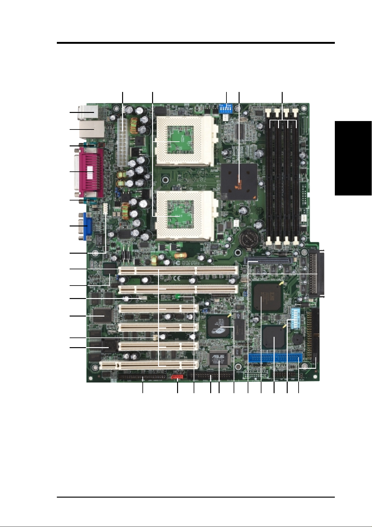
2.2 TR-DLS Motherboard Components
See opposite page for locations.
Location
®
Processor Support (2) Socket 370 for Pentium
Processors ................................................................................. 2
III Coppermine and Tualatin™
MB Components
2. FEA TURES
Chipsets ServerWorks
ServerWorks
Low Pin Count (LPC) Super-I/O Chipset .............................. 19
4Mbit Flash ROM .................................................................. 17
Main Memory Maximum 4GB support
(4) DIMM Sockets.................................................................... 5
PC133 “registered” SDRAM support
Expansion Slots (2) 64-bit / 66MHz 3V (PCI1, PCI2)...................................... 22
(4) 32-bit / 33MHz 5V (PCI3, PCI4, PCI5, PCI6) ................. 22
System I/O (1) Floppy Disk Drive Connector........................................... 13
(2) IDE Connectors (UltraDMA100 support) .......................... 6
(1) Parallel Port ............................................................ (Top) 26
(1) Serial Port 1 (COM1).........................................(Bottom) 27
(1) Serial Port 2 (COM2).........................................(Bottom) 25
(2) USB Ports .......................................................... (Bottom) 28
(1) USB Header ...................................................................... 23
(1) PS/2 Mouse Ports.................................................... (Top) 29
(1) PS/2 Keyboard Ports ..........................................(Bottom) 29
®
RCC Champion LE-T North Bridge................. 4
®
RCC Champion CSB5 South Bridge ................ 8
®
Network Features Intel
Video Features ATI Rage-XL PCI VGA Controller ........................................ 11
SCSI Features LSI 64-bit 66MHz Ultra160/320 SCSI controller ..................... 9
Frequency Setting DIP Switches ........................................................................ 3, 7
Hardware Monitoring System Voltage Monitoring (integrated in ASUS ASIC) ....... 12
Power ATX 24-pin Power Supply Connector...................................... 1
Special Features Intelligent Platform Management Interface (IPMI) ............... 15
Form Factor EATX (12 in. x 10 in.)
82550 Fast Ethernet Controller .................................... 21
(1) RJ-45 Fast-Ethernet Port......................................... (Top) 28
Wake-On-LAN Connector...................................................... 20
Wake-On-Ring Connector ...................................................... 18
(1) VGA Monitor Port ........................................................... 24
Onboard SCSI Connectors ..................................................... 10
(4) Fan Power & Speed Monitoring Connectors (see layout on p. 14)
eRMC Connector.................................................................... 16
Onboard LED ......................................................................... 14
12
ASUS TR-DLS User’s Manual
2. FEATURES
2.2.1 Component Locations
29
28
27
26
25
24
23
1 354
2
2. FEA TURES
Component Location
22
21
20
19
18
17
10 89 71112131516 14
6
ASUS TR-DLS User’s Manual 13
3. HARDWARE SETUP
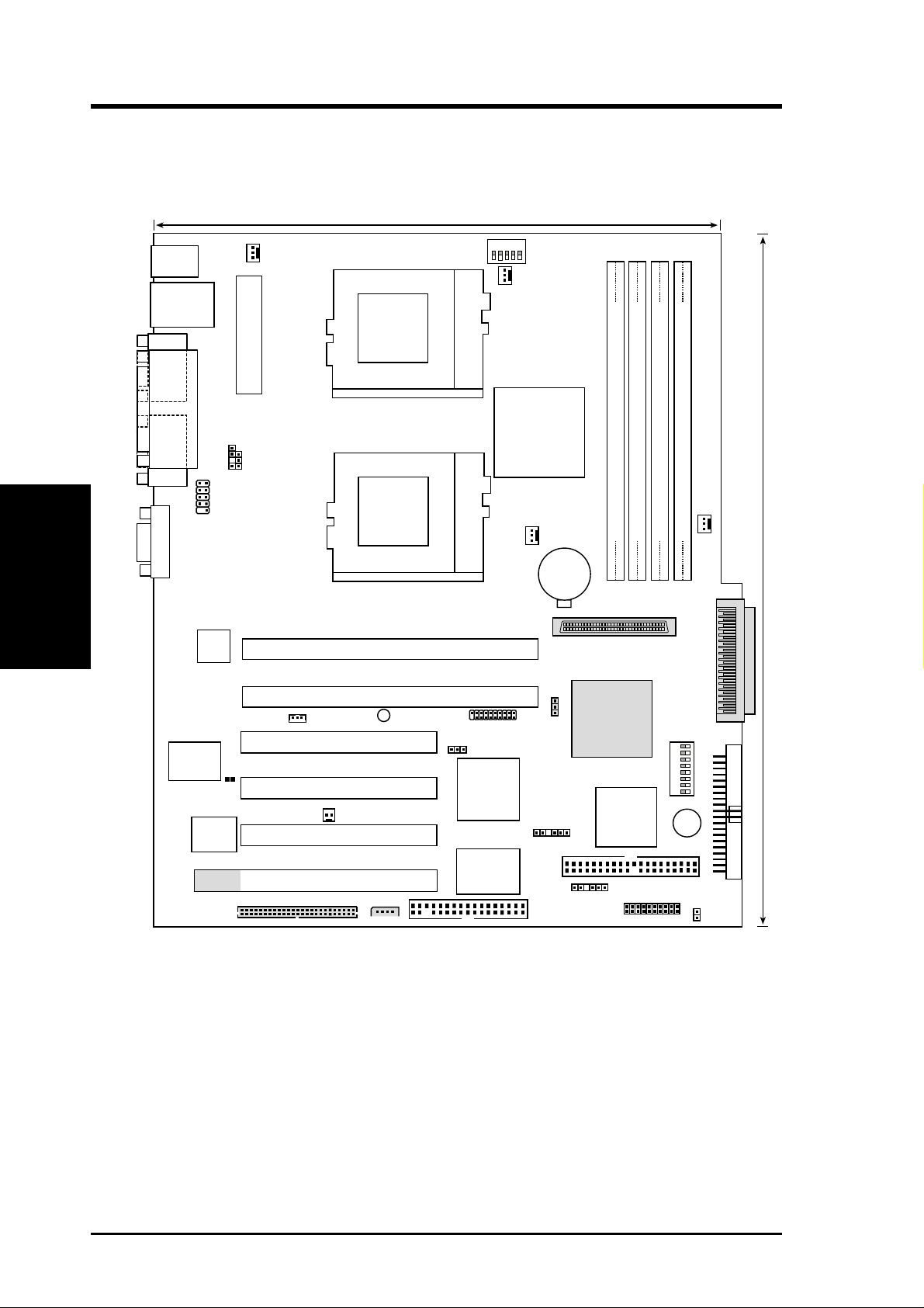
3.1 TR-DLS Motherboard Layout
24.4cm (9.6in)
5
PS/2
T: Mouse
B: Keyboard
Bottom:
USB1
USB2
COM1
Top:
RJ-45
CHA_FAN1
ATX_POWER
1234
CLKSW
CPU_FAN1
PGA 370
Motherboard Layout
COM2
3. H/W SETUP
VGA
Super
PARALLEL PORT
CHASSIS
USBPORT
Intel
Fast
Ethernet
I/O
CLRCMOS
4Mbit
Flash
BIOS
TR-DLS
KBPWR
PCI1 (64-bit, 66MHz 3V)
PCI2 (64-bit, 66MHz 3V)
WOL_CON
PCI3 (32-bit, 33MHz 5V)
PCI4 (32-bit, 33MHz 5V)
WOR
PCI5 (32-bit, 33MHz 5V)
PCI6 (32-bit, 33MHz 5V)
eRMC CONNECTOR
IPMI
LED1
ServerWorks
North Bridge
CPU_FAN2
PGA 370
Digital Flat Panel
(DFP) Connector
VGAEN
ATI
RAGE XL
VGA
Controller
BPSMB
ASUS
ASIC
with Hardware
Monitor
®
RCC
LE-T
CR2032 3V
Lithium Cell
CMOS Power
35 68
68-Pin Ultra160/Ultra2-Wide
SCSI Connector
SCSIEN
FLOPPY
LSI
Controller
BPSMB
CHA_FAN2
DIMM Socket 0 (72-bit, 168-pin module)
DIMM Socket 1 (72-bit, 168-pin module)
DIMM Socket 2 (72-bit, 168-pin module)
DIMM Socket 3 (72-bit, 168-pin module)
01
23
45
67
30.5cm (12in)
PANEL
341
5678
1234
CONFIG
®
BUZZER
Primary IDE1
Secondary IDE2
SCSI-B
SCSI Connector
68-Pin Ultra160/Ultra2-Wide
HD_LED
SCSI-A
SCSI
ServerWorks
RCC
CSB5
South Bridge
14
NOTE: The SCSI and ASMC features, eRMC connector, and IPMI
connectors are optional components. These are grayed out in the above
motherboard layout.
ASUS TR-DLS User’s Manual

3. HARDWARE SETUP
3.2 Layout Contents
Motherboard Settings
1) CLKSW p. 18 CPU Bus Frequency Setting
2) CONFIG p. 19 CPU Core Bus Frequency Multiplier
3) SCSIEN p. 21 SCSI Setting
4) VGAEN p. 21 VGA Setting
5) KBPWR p.22 Keyboard Power Setting
6) CLRCMOS p.22 Clear CMOS
Expansion Slots
1) DIMM 0/1/2/3 p. 23 168-Pin System Memory Support
2) CPU p. 25 Central Processing Unit (CPU)
3) PCI1/2/3/4/5/6 p.27 64-bit/32-bit PCI Bus Expansion Slot
External Connectors
1) PS2KBMS p. 29 PS/2 Mouse Port (6-pin female)
2) PS2KBMS p. 29 PS/2 Keyboard Port (6-pin female)
3) USB p. 29 Universal Serial Bus Ports 0 & 1 (two 4-pin female)
4) RJ-45 p. 30 Fast-Ethernet Connector (RJ-45)
5) PRINTER p. 30 Parallel Port (25-pin female)
5) COM1/COM2 p. 30 Serial Port COM1/COM2 Ports (two 9-pin male)
6) VGA p. 30 Monitor (VGA) Port (15-pin female)
Internal Connectors
1) IDE1/IDE2 p. 31 Primary/Secondary IDE Connectors (two 40-1 pin)
2) HDLED p. 32 IDE/SCSI Activity LED (2-pin)
3) FLOPPY p. 32 Floppy Disk Drive Connector (34-1 pin)
4) WOL_CON p. 33 Wake-On-LAN Connector (3-pin)
5) WOR p. 33 Wake-On-Ring Connector (2-pin)
6) SCSI-A/SCSI-B p.34 68-pin Ultra160 SCSI Connectors (two 68-pin)
7) CPU_FAN1/2 p.35 CPU and Chassis Fan Connectors (four 3-pin)
3. H/W SETUP
Layout Contents
CHA_FAN1/2
8) CHASSIS p. 33 Chassis Open Alarm Lead (4-1 pin)
9) SMB, BPSMB p.36 SMBus Connectors (two 6-1 pins)
10 USBPORT p. 36 Universal Serial Port Header (10-1pin male)
11) ATXPWR p. 37 ATX Power Supply Connector (20/24-pin)
ASUS TR-DLS User’s Manual 15

12) eRMC p. 37 ASUS Server Management Card Connector
13) IPMI p. 38 Intelligent Platform Management Interface
14) NIC (PANEL) p.38 NIC Activity LED (2-pin)
15) STATUS (PANEL) p. 38 Status Activity LED (2-pin)
16) PWRSW (PANEL) p. 38 ATX Power Switch/Soft Off Lead (2-pin)
17) RESET (PANEL) p. 39 Reset Switch Lead (2-pin)
18) PWR.LED (PANEL) p. 39 System Power LED Lead (3-1 pin)
19) NMI (PANEL) p. 39 Non-Mask Interrupt Switch (2-pin)
20) SPEAKER (PANEL) p. 39 System Warning Speaker Connector (4-pin)
21) IDELED (PANEL) p.39 IDE/SCSI Activity LED (2-pin)
Motherboard Settings
3. H/W SETUP
3. HARDWARE SETUP
(50-pin)
(4-pin)
16
ASUS TR-DLS User’s Manual
3. HARDWARE SETUP
3.3 Hardware Setup Procedure
Complete the following steps before using your computer:
1. Check motherboard settings
2. Install memory modules
3. Install the Central Processing Unit (CPU)
4. Install a CPU terminator, if you installed only one CPU.
5. Install Expansion Cards
6. Connect ribbon cables, panel wires, and power supply cables
7. Configure the BIOS parameter settings
Take note of the following precautions before you install motherboard components
or change any motherboard settings.
1. Unplug the power cord from the wall socket before touching any internal
component.
2. Use a grounded wrist strap or touch a safely grounded object, such as the
power supply case, before handling components to avoid damaging them
due to static electricity.
3. Hold components by the edges and do not touch the ICs on them.
4. Whenever you uninstall any component, place the components on a grounded
antistatic pad or in the bag that came with the component.
5. Before you install or r emove any component, ensure that the A TX power
supply is switched off or the power cord is detached from the power
supply. Failure to do so may cause severe damage to the motherboard,
peripherals, and/or components.
3. H/W SETUP
Motherboard Settings
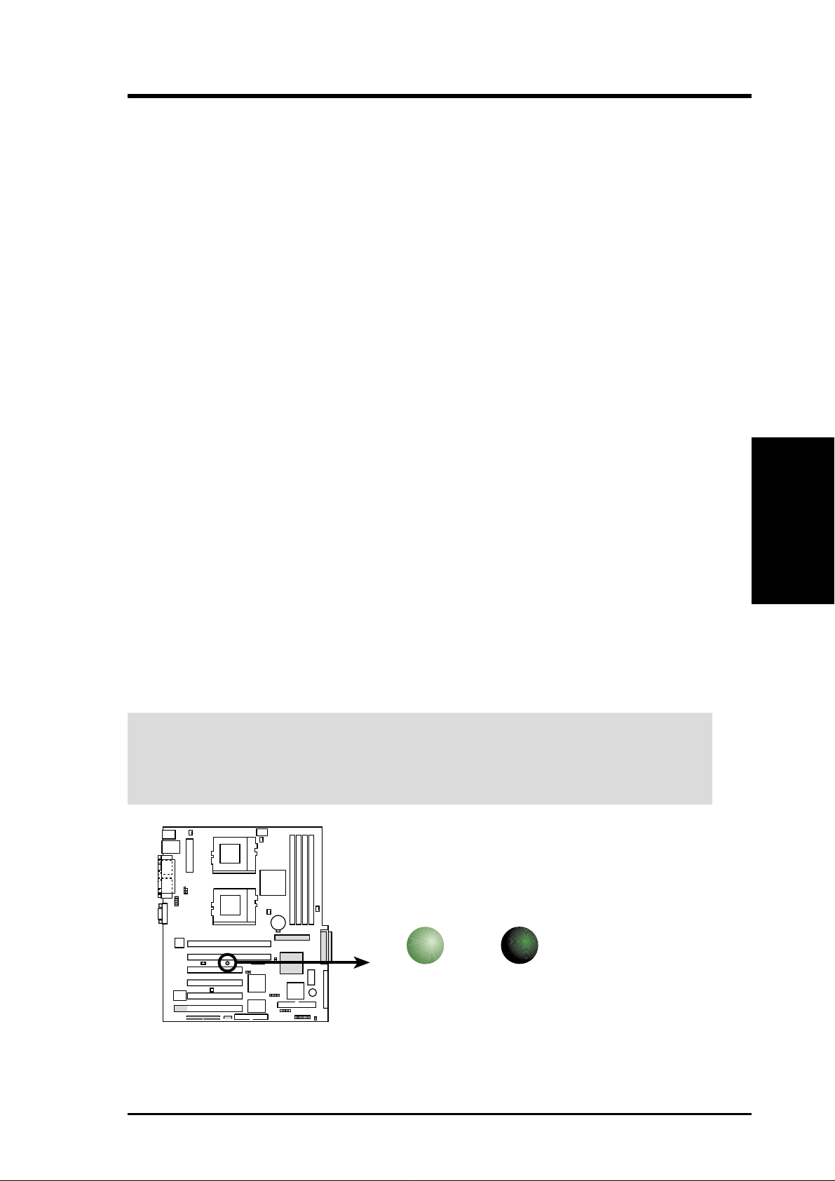
IMPORTANT: When lighted, the onboard LED indicates that the system is either
ON, in sleep mode, or in soft-off mode. Make sure that the LED is turned OFF
before you install or remove any motherboard component.
TR-DLS
LED1
ON
Standby
Power
TR-DLS Onboard LED
OFF
Powered
Off
ASUS TR-DLS User’s Manual 17
3. HARDWARE SETUP
3.4 Motherboard Settings
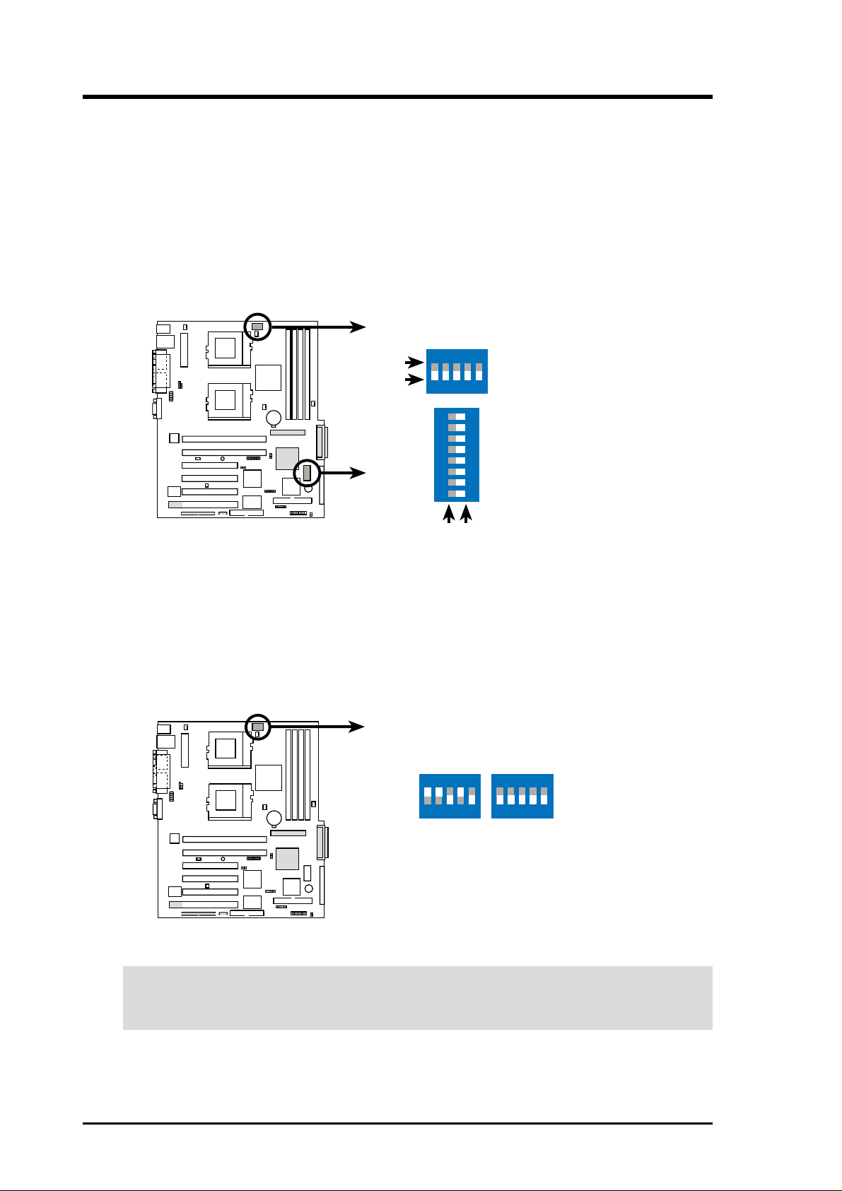
3.4.1 Switches
You may change the CPU core bus frequency multiple using the DIP switches. The
white block on a DIP switch represents the ON or OFF position. The figure below
shows the location of the DIP switches on the motherboard and the function of each
switch.
TR-DLS
TR-DLS DIP Switches
ON
OFF
CONFIG
CLKSW
ON
12345
ON
ON
1. Frequency Selection
2. Frequency Selection
3. Frequency Selection
4. Frequency Selection
5. Frequency Selection
1. Reserved
2. External Buzzer Setting
3. Reserved
4. Reserved
5. Frequency Multiple
12345678
6. Frequency Multiple
7. Frequency Multiple
8. Frequency Multiple
OFF
1. CPU Frequency Selection (CLKSW)
This option tells the clock generator what frequency to send to the CPU. This
allows the selection of the CPU external frequency (or bus clock). The bus clock
multiplied by the the frequency multiple equals the CPU internal frequency (the
advertised CPU speed).
TR-DLS
CPU
ON
12345
100MHz
ON
12345
133MHz
TR-DLS CPU External Frequency Selection
CAUTION! Set the CPU frequency only to the recommended settings. Frequencies
other than the recommended CPU bus frequencies are not guaranteed to be stable.
CLKSW
18
ASUS TR-DLS User’s Manual
3. HARDWARE SETUP
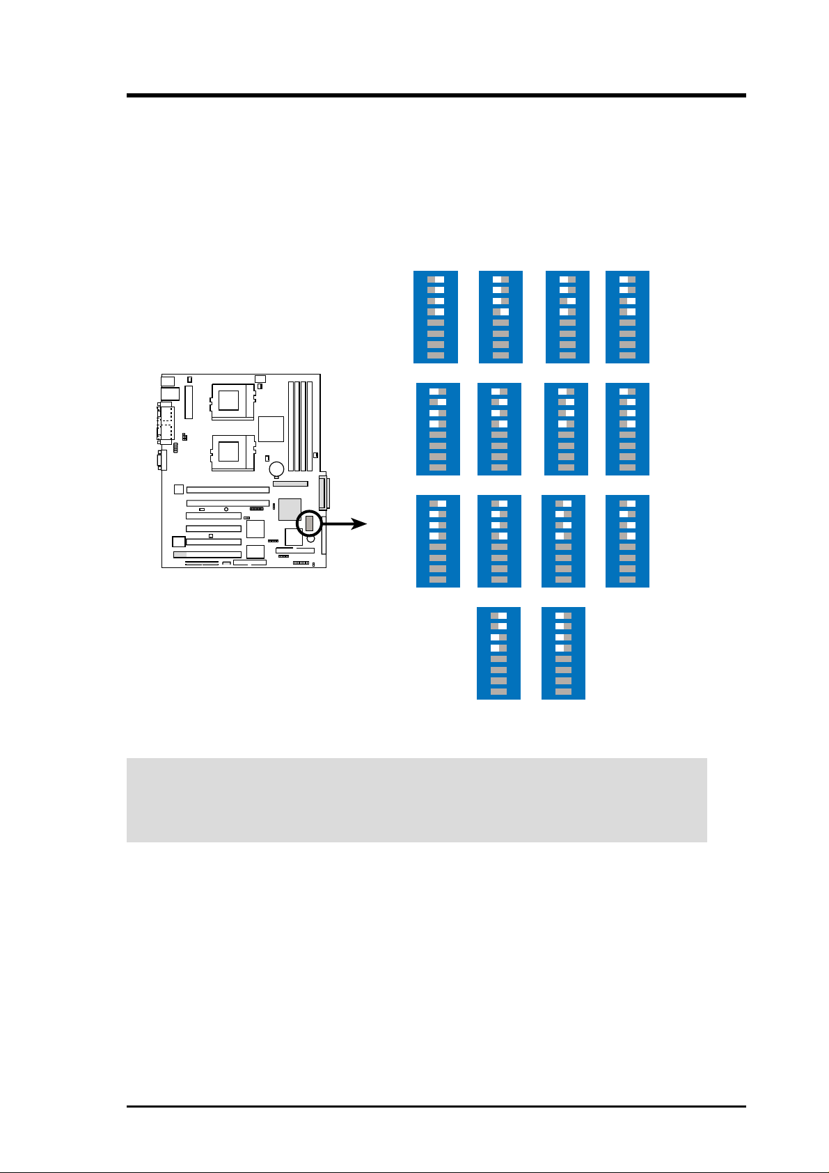
2. CPU Core Bus Frequency Multiple (Switches 5-8)
These switches allow you to set the frequency multiple between the CPU internal
and external frequencies. Set these switches in conjunction with the settings of
the CLKSW switches.
The following figure shows the switch settings for a Pentium III Coppermine
CPU. See next page for Pentium III Tualatin CPU settings.
Coppermine
TR-DLS
TR-DLS CPU (Coppermine)
Frequency Multiple Selection
ON
2.0x
ON
4.0x
ON
6.0x
12345678
12345678
12345678
8.0x
ON
2.5x
ON
4.5x
ON
6.5x
ON
12345678
12345678
12345678
12345678
ON
3.0x
ON
5.0x
ON
7.0x
ON
2.0x
12345678
12345678
12345678
12345678
ON
3.5x
ON
5.5x
ON
7.5x
12345678
12345678
12345678
CAUTION! The option to set the CPU core bus frquency multiple is available
only on unlocked CPUs. If you are using a locked CPU, setting the aboce switches
does not produce any effect.
ASUS TR-DLS User’s Manual 19
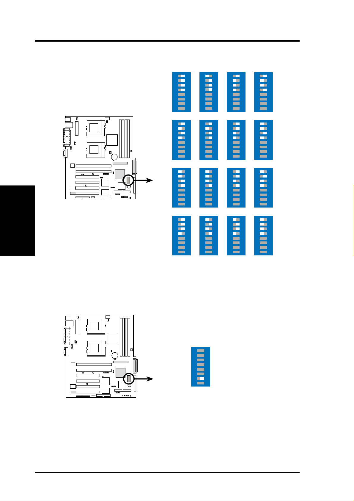
3. HARDWARE SETUP
The following figure shows the CPU core bus frequency settings for Pentium III
Tualatin CPU.
Tualatin
12345678
TR-DLS
ON
4.0x
12345678
5.5x
ON
ON
6.0x
12345678
ON
6.5x
12345678
Motherboard Settings
3. H/W SETUP
TR-DLS CPU (Tualatin)
Frequency Multiple Selection
3. External Buzzer Setting (Switch 2)
This switch allows you to activate the external buzzer. Set to ON to enable the
buzzer. Set to OFF to disable the buzzer.
ON
7.0x
ON
9.0x
ON
11.0x
12345678
7.5x
12345678
9.5x
12345678
11.5x
ON
ON
ON
12345678
12345678
10.0x
12345678
12.0x
ON
8.0x
ON
ON
12345678
12345678
10.5x
12345678
ON
8.5x
ON
ON
4.0x
12345678
12345678
12345678
20
TR-DLS
TR-DLS External Buzzer Setting
ASUS TR-DLS User’s Manual
1 2 345678
ON
External Buzzer
ON: Enable
OFF: Disable
3. HARDWARE SETUP
3.4.2 Jumpers
The jumpers on the motherboard allow you to change some feature settings to suit
your customized system configuration.
IMPORTANT! Before changing any jumper setting, make sure to read the jumper
descriptions and setting requirements in this section.
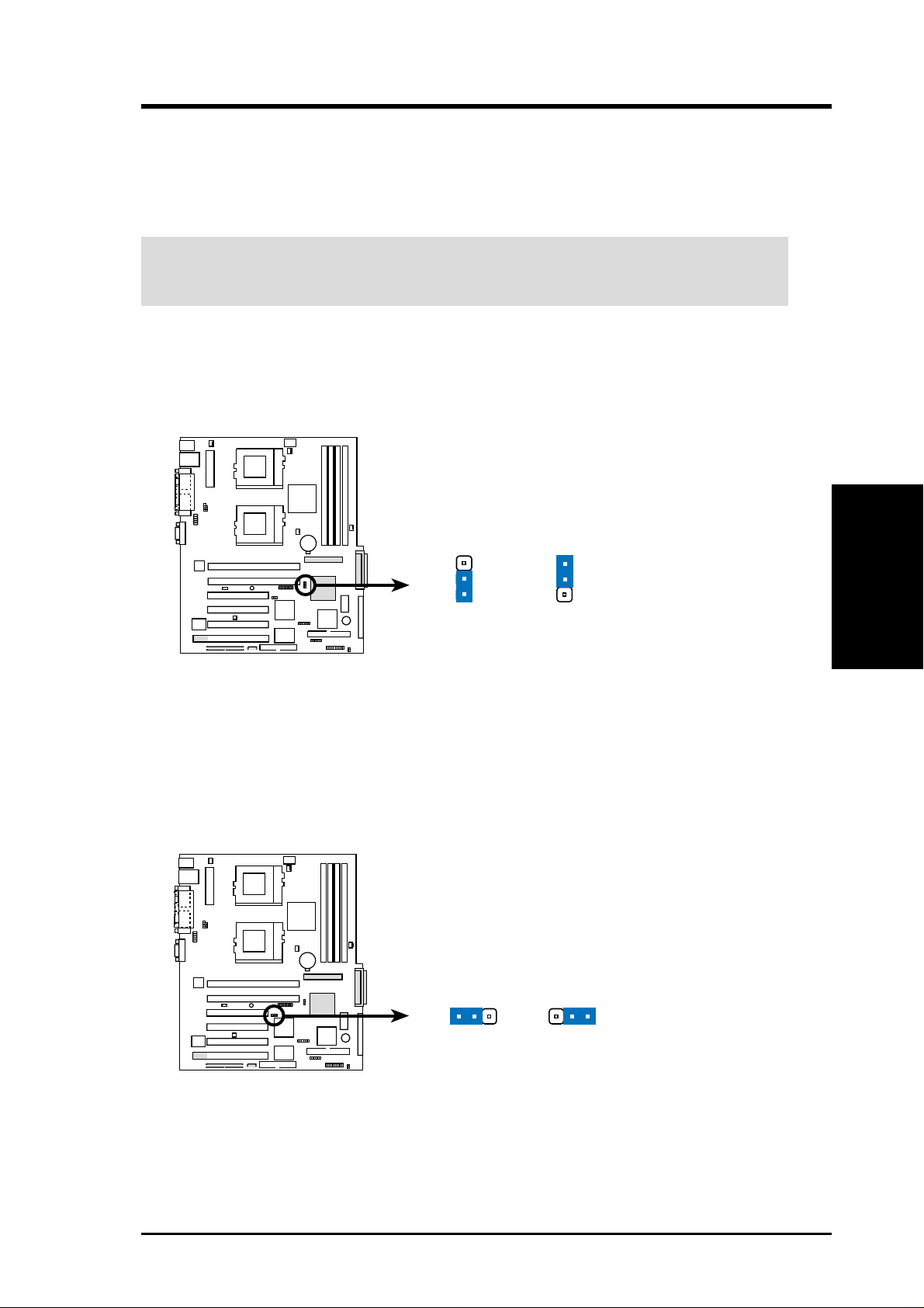
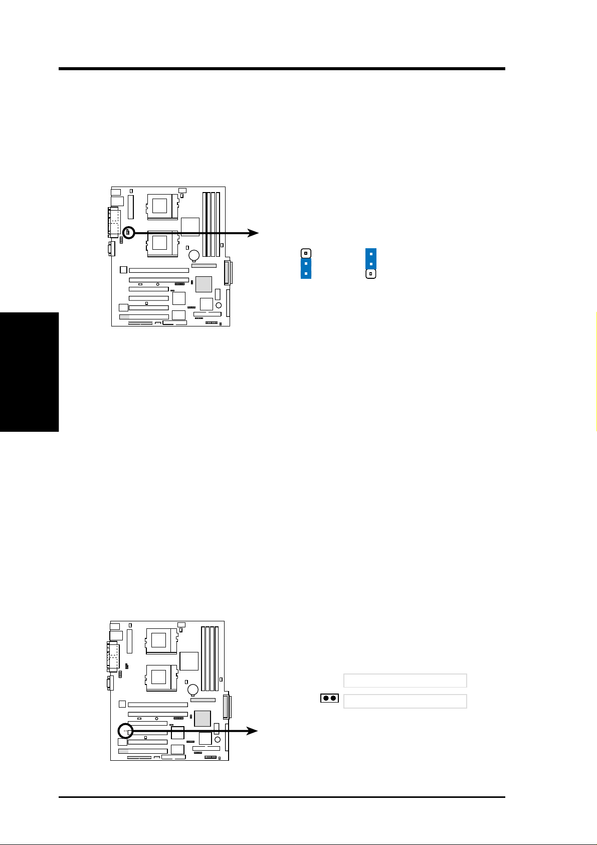
1. SCSI Settings (3-pin SCSIEN)
This jumper allows you to enable or disable the onboard SCSI function. Set to
Enable (pins 1-2) if you wish to use SCSI devices.
TR-DLS
SCSIEN
3
2
1
Enable
(Default)
TR-DLS SCSI Setting
2
Disable
2. VGA Settings (3-pin VGAEN)
This jumper allows you to enable or disable the onboard VGA function. Set to
Enable (pins 1-2) if you wish to use the onboard VGA capability. Set to Disable
(pins (2-3) if you install a VGA card.
TR-DLS
VGAEN
12
23
3. H/W SETUP
Motherboard Settings
TR-DLS VGA Setting
ASUS TR-DLS User’s Manual 21
Enable
(Default)
Disable
3. HARDWARE SETUP
3. Keyboard Power Settings (3-pin KBPWR)
This jumper allows you to enable or disable the keyboard wake-up feature. Set
this jumper to pins 2-3 (5VSB) if you wish to wake up the computer when you
press a key on the keyboard. This feature requires an ATX power supply that can
supply at least 1A on the +5VSB lead, and a corresponding setting in the BIOS
(see section 4.5.1 Power Up Control).
Motherboard Settings
3. H/W SETUP
TR-DLS Keyboard Power Setting
4. Clear RTC RAM (CLRCMOS)
These two solder points allow you to clear the RTC RAM in CMOS. You can
clear the CMOS memory of date, time, and system setup parameters by erasing
the CMOS Real Time Clock (RTC) RAM. The RAM data that include system
setup information, such as system passwords, is powered by the onboard button
cell battery.
To erase the RTC RAM:
1. Turn OFF the computer and unplug the power cord.
2. Remove the battery.
3. Short the solder points for a few seconds.
4. Re-install the battery.
5. Plug the power cord and turn ON the computer.
6. Hold down the <Del> key during the boot process and enter BIOS setup to
TR-DLS
re-enter CMOS data.
2
1
5V
(Default)
KBPWR
3
2
5VSB
22
TR-DLS
TR-DLS Clear RTC RAM
ASUS TR-DLS User’s Manual
CLRCMOS
Short solder points
to Clear CMOS
PCI3 (32-bit, 33MHz 5V)
PCI4 (32-bit, 33MHz 5V)

3. HARDWARE SETUP
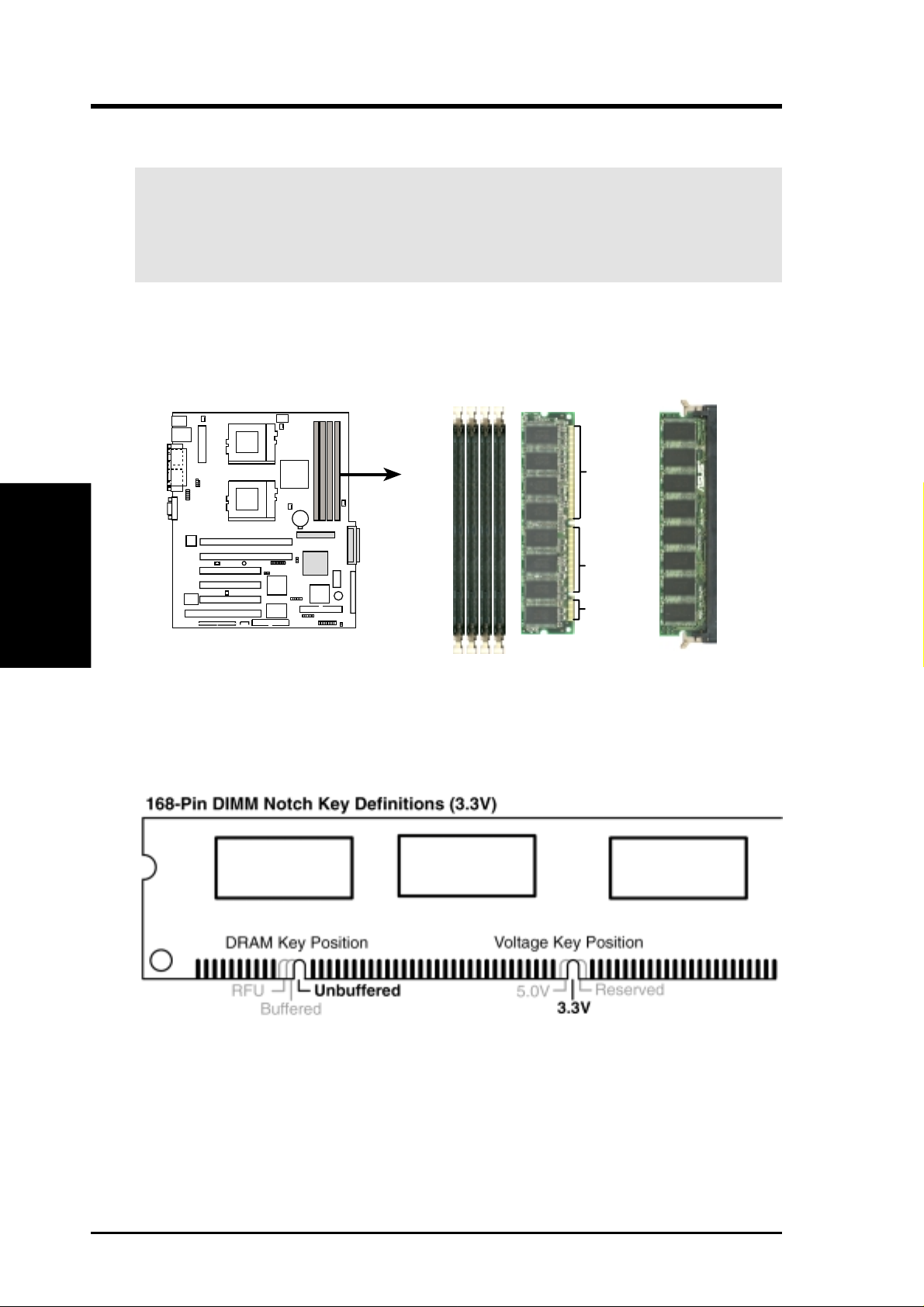
3.5 System Memory
This motherboard uses only Dual Inline Memory Modules (DIMMs). Four DIMM
sockets are available for 3.3Volt (power level) registered Synchronous Dynamic
Random Access Memory (SDRAM) of 16MB, 32MB, 64MB, 128MB, 256MB,
512MB, or 1GB densities with Serial Presence Detect (SPD) and Error Check and
Correction (ECC). The motherboard supports a memory configuration of up to 4GB.
One side (with memory chips) of the DIMM takes up one row on the motherboard.
3.5.1 Memory Configurations
Install memory in any of the following combinations:
DIMM Location 168-pin DIMM Total Memory
Socket 0 (Rows 0&1) SDRAM 128MB, 256MB, 512MB, 1GB x1
Socket 1 (Rows 2&3) SDRAM 128MB, 256MB, 512MB, 1GB x1
Socket 2 (Rows 4&5) SDRAM 128MB, 256MB, 512MB, 1GB x1
Socket 3 (Rows 6&7) SDRAM 128MB, 256MB, 512MB, 1GB x1
Total System Memory (Max. 4GB) =
IMPORTANT: The system chipset only supports 64Mbit, 128Mbit, and 256Mbit
“registered” SDRAMs with ECC. Make sure to use the specified DIMM types for
smooth system operation.
3. H/W SETUP
System Memory
ASUS TR-DLS User’s Manual 23
3. HARDWARE SETUP
3.5.2 Memory Installation
WARNING! Make sure that you unplug the power supply when adding or
removing memory modules or other system components. Failure to do so may
cause severe damage to both the motherboard and expansion cards (see 3.3
Hardware Setup Procedure for more information).
Insert a DIMM into the DIMM socket as shown. Because the number of pins are
different on either side of the breaks, the module only fits in one direction. SDRAM
DIMMs have different pin contacts on each side.
System Memory
3. H/W SETUP
Use only 3.3Volt “registered” SDRAM DIMMs. T o determine the DIMM type, check
the notches on the DIMMs (see the figure below).
TR-DLS
TR-DLS 168-Pin DIMM Sockets
88 Pins
60 Pins
20 Pins
The notches on the DIMM shifts between left, center, or right to identify the type
and also to prevent the wrong type from being inserted into the DIMM slot on the
motherboard. You must tell your retailer the correct DIMM type before purchasing.
This motherboard supports four clock signals per DIMM.
24 ASUS TR-DLS User’s Manual
3. HARDWARE SETUP
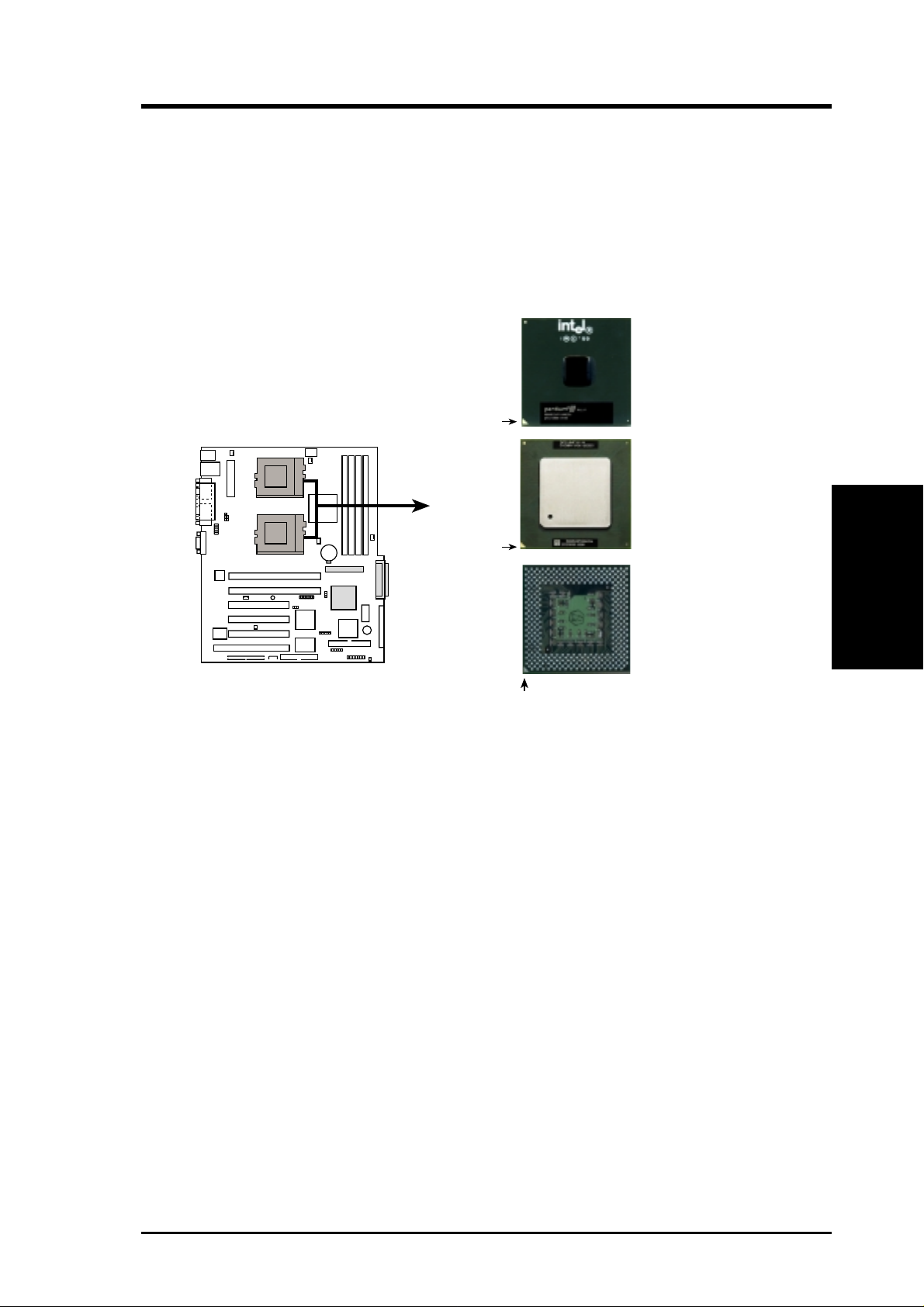
3.6 Central Processing Unit (CPU)
The motherboard comes with a dual Socket 370 for Intel Pentium III Coppermine
(256KB L2) and Tualatin (512KB L2) CPUs running up to 1.53+GHz with 100/
133MHz Front Side Bus (FSB). The following illustration shows the location of the
CPU sockets on the motherboard and the correct CPU and terminator orientation.
Pentium III
(Coppermine)
FC-PGA
Gold Arrow
Pentium III
(Tualatin)
TR-DLS
Gold Arrow
TR-DLS Socket 370
Silver Arrow
FC-PGA2
Socket 370
Terminator
(Use when only one
CPU is installed)
Note in the illustration that the CPU and the terminator have marks (usually a notch
or a gold mark on one corner) to help you identify the proper orientation and enable
you to correctly install them. It is important that you match the marked corner of the
CPU and terminator with the corresponding corner on the socket so as not to damage
the CPU pins.
NOTE: Do not forget to set the correct Bus Frequency and Multiple
(frequency multiple setting is available only on unlocked processors) for the
processor to avoid start-up problems.
CPU
3. H/W SETUP
ASUS TR-DLS User’s Manual 25
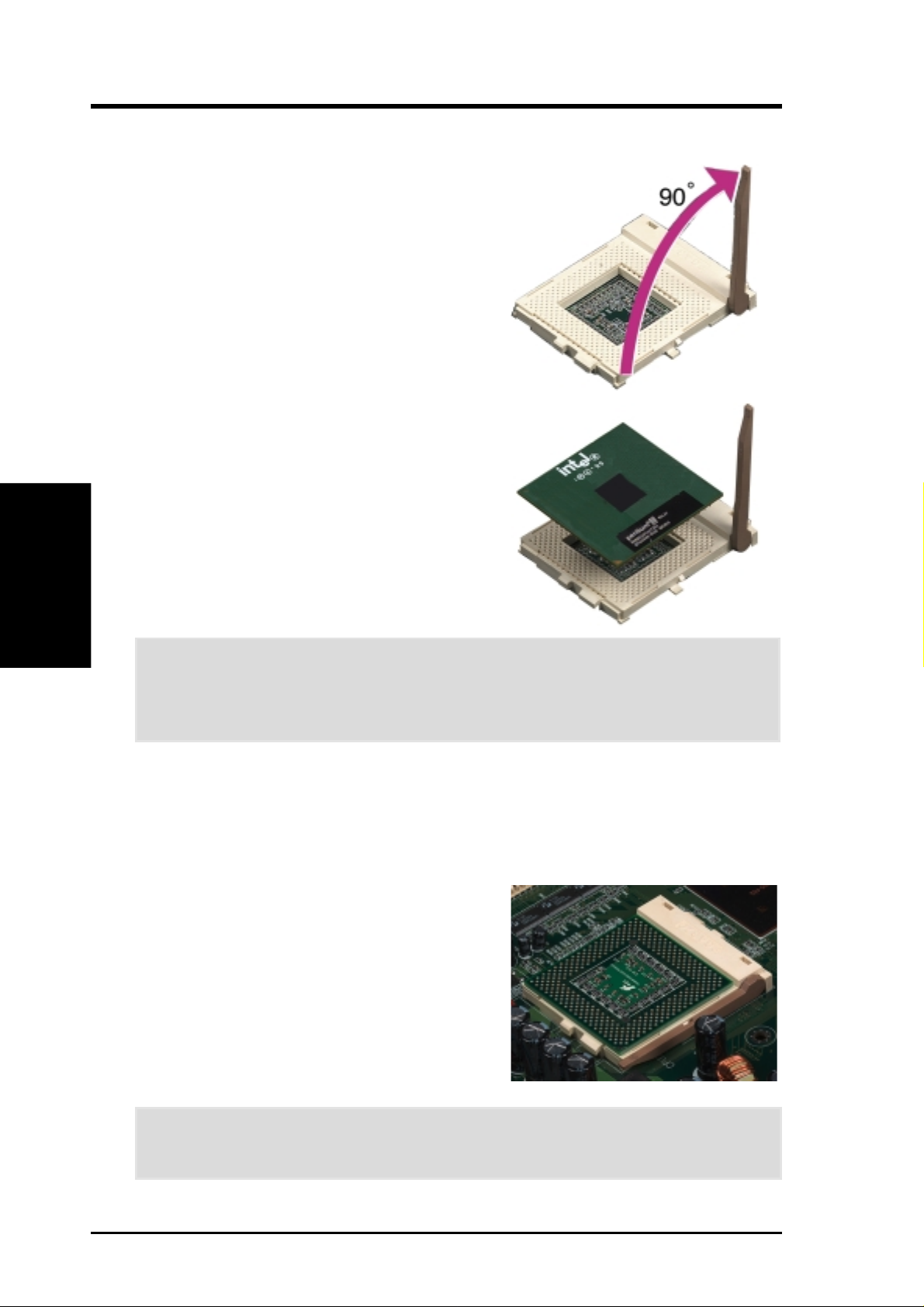
3.6.1 Installing the CPU and Terminator
Follow these steps to install a CPU.
1. Locate the ZIF socket on the motherboard.
2. Unlock the socket by pressing the lever
3. Position the CPU above the socket such
CPU Installation
3. H/W SETUP
4. Carefully insert the CPU into the socket
3. HARDWARE SETUP
sideways then lifting it up to a 90°-100°
angle.
that its notched or marked corner matches
the socket corner near the end of the lever,
while making sure that the CPU is parallel
to the socket.
until it fits in place.
CAUTION! The CPU fits only in one orientation. Do not force the CPU into the
socket to prevent bending the pins and damaging the CPU. If the CPU does not
fit completely, check its orientation or check for bent pins.
5. When the CPU is in place, press it firmly on the socket while you push down the
socket lever to secure the CPU. The lever clicks on the socket indicating that it
is locked.
6. Install a CPU heatsink. Refer to the documentation that came with the heatsink.
7. Install the CPU terminator the same way
as you would install a CPU. The figure on
the right shows an installed CPU
terminator.
CAUTION! DO NOT install a heatsink on the terminator! It will cause system
damage!
26 ASUS TR-DLS User’s Manual
3. HARDWARE SETUP
3.7 Expansion Cards
W ARNING! Unplug the power supply when adding or removing expansion cards
or other system components. Failure to do so may cause severe damage to both
your motherboard and expansion cards.
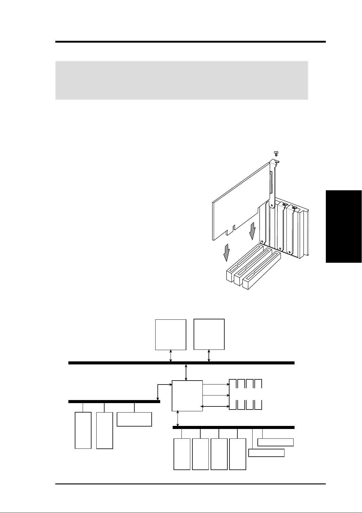
3.7.1 Expansion Card Installation Procedure
1. Read the documentation for your expansion card and make any necessary
hardware or software settings for your expansion card, such as jumpers.
2. Remove your computer system’s cover and the
bracket plate on the slot you intend to use. Keep
the bracket for possible future use.
3. Carefully align the card’s connectors and press
firmly.
4. Secure the card on the slot with the screw you
removed above.
5. Replace the computer system’s cover.
6. Set up the BIOS if necessary
(see 4.4.3 PCI Configuration)
7. Install the necessary software drivers for your
expansion card.
3. H/W SETUP
Expansion Cards
Peer-to-Peer PCI Bus Configuration Diagram
Peer-to-Peer PCI Bus
Configuration Diagram
Secondary PCI Bus (66/33MHz)
PCI-1
64-bit
PCI-2
64-bit
LSI SCSI
1010R/1030
Socket 370
CNB30LE
PCI-3
32-bit
Socket 370
MA
PCI-4
32-bit
Cntl
MD
100/133MHz
PCI-5
32-bit
PCI-6
32-bit
RCC
Primary PCI Bus (33MHz)
100/133 MHz
Registered DIMM
Intel 82550
ATI RageXL
ASUS TR-DLS User’s Manual 27
3. HARDWARE SETUP
3.7.2 Assigning IRQs for Expansion Cards
Some expansion cards need an IRQ to operate. Generally , an IRQ must be exclusively
assigned to one use. In a standard design, there are 16 IRQs available but most of them
are already in use, leaving 6 IRQs free for expansion cards. If the motherboard has PCI
audio onboard, an additional IRQ will be used. If the motherboard also has MIDI
enabled, another IRQ will be used, leaving 4 IRQs free.
The following table lists the default IRQ assignments for standard PC devices. Use this
table when configuring your system and for resolving IRQ conflicts.
ISA Interrupt (IRQ) Assignments
ISA INT Priority Standard Function
ISA 00 1 System Timer
ISA 01 2 Keyboard Controller
Expansion Cards
3. H/W SETUP
*These IRQs are usually available for PCI devices.
ISA 02 N/A Programmable Interrupt
ISA 03* 11 Communications Port (COM2)
ISA 04* 12 Communications Port (COM1)
ISA 05* 13 Sound Card (sometimes LPT2)
ISA 06 14 Floppy Disk Controller
ISA 07* 15 Printer Port (LPT1)
ISA 08 3 System CMOS/Real Time Clock
ISA 09* 4 ACPI Mode when used
ISA 10* 5 IRQ Holder for PCI Steering
ISA 11* 6 IRQ Holder for PCI Steering
ISA 12* 7 PS/2 Compatible Mouse Port
ISA 13 8 Numeric Data Processor
ISA 14* 9 Primary IDE Channel
ISA 15* 10 Secondary IDE Channel
PCI Interrupt (IRQ) Assignments
PCI Slot PCI INTA PCI INTB PCI INTC PCI INTD
1 (64-bit) PCI 5 PCI 13 PCI 15 PCI 14
2 (64-bit) PCI 6 PCI 14 PCI 13 PCI 15
3 (32-bit) PCI 0 PCI 9 PCI 12 PCI 11
4 (32-bit) PCI 1 PCI 10 PCI 9 PCI 12
5 (32-bit) PCI 2 PCI 11 PCI 10 PCI 9
6 (32-bit) PCI 3 PCI 12 PCI 11 PCI 10
28 ASUS TR-DLS User’s Manual

3. HARDWARE SETUP
3.8 Connectors
3.8.1 External Connectors
1) PS/2 Mouse Port (Green 6-pin PS2KBMS)
The system will direct IRQ12 to the PS/2 mouse if one is detected. If one is not
detected, expansion cards can use IRQ12.
PS/2 Mouse (6-pin female)
2) PS/2 Keyboard Port (Purple 6-pin PS2KBMS)
This connection is for a standard keyboard using an PS/2 plug (mini DIN). This
connector does not allow standard A T size (large DIN) keyboard plugs. You
may use a DIN to mini DIN adapter on standard AT keyboards.
Connectors
3. H/W SETUP
PS/2 Keyboard (6-pin female)
3) Universal Serial BUS Ports 1 & 2 (Black two 4-pin USB)
Two USB ports are available for connecting USB devices.
USB 1
Universal Serial Bus (USB) 2
ASUS TR-DLS User’s Manual
29
3. HARDWARE SETUP
4) Fast Ethernet LAN Port (RJ-45)
The RJ-45 connector allows connection to a Local Area Network (LAN) through
a network hub.
RJ45
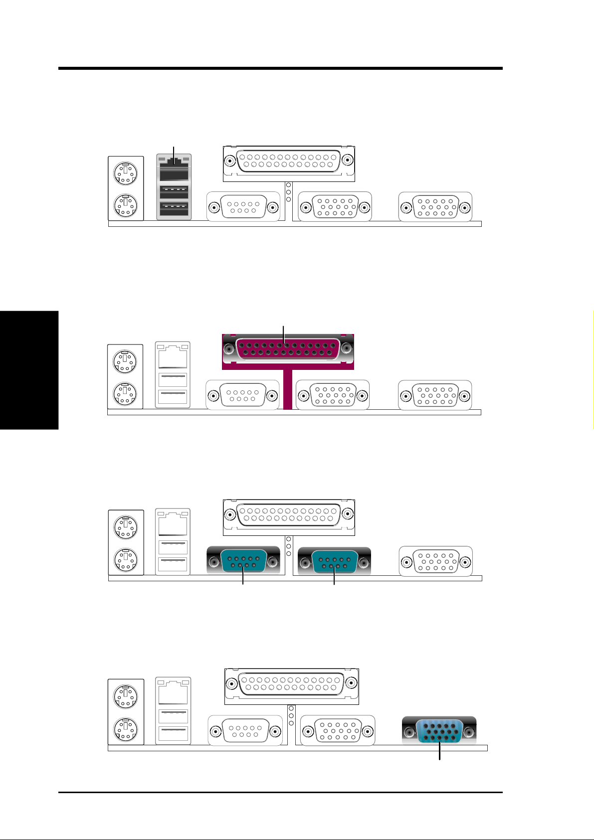
5) Parallel Port (Burgundy 25-pin PRINTER)
A 25-pin port is available for a parallel printer. Enable the parallel port and
select the IRQ through Onboard Parallel Port parameter in BIOS. (See 4.4.2
I/O Device Configuration).
3. H/W SETUP
Connectors
Parallel (Printer) Port (25-pin female)
6) Serial Port (Teal/Turquoise 9-pin COM1)
One serial port is available for pointing devices or other serial devices. T o enable
the port, see Onboard Serial Port 1 in 4.4.2 I/O Device Configuration.
COM 1
Serial Ports (9-pin male)
COM 2
7) VGA Port (Blue 15-pin VGA)
This connector is for a VGA monitor and other VGA-compatible devices.
30
ASUS TR-DLS User’s Manual
VGA Monitor (15-pin Female)
 Loading...