

Page 1
How to connect DSI and CSI cable to tinker board
DSI, CSI cable can be use will no difference, those cable is the same.
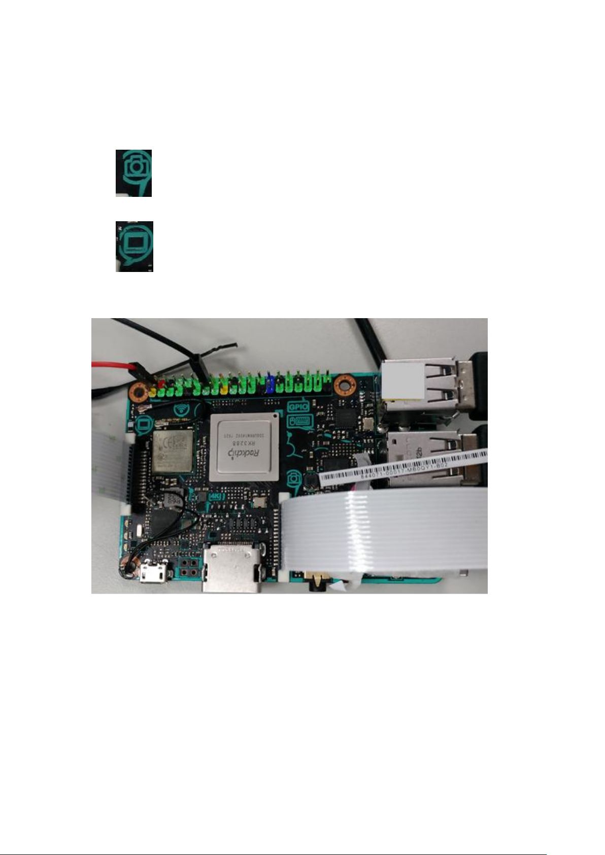
CSI connect to the middle of tinker board, please refer icon print on board as follows:
DSI connect to the boundary of tinker board, please refer icon print on board as follows:
DSI panel need extra 5V power. You can USB to supply, or thinker board can output 5V by
GPIO PIN, red line is for positive(+),black line is for negative(-) , as follow.
Page 2
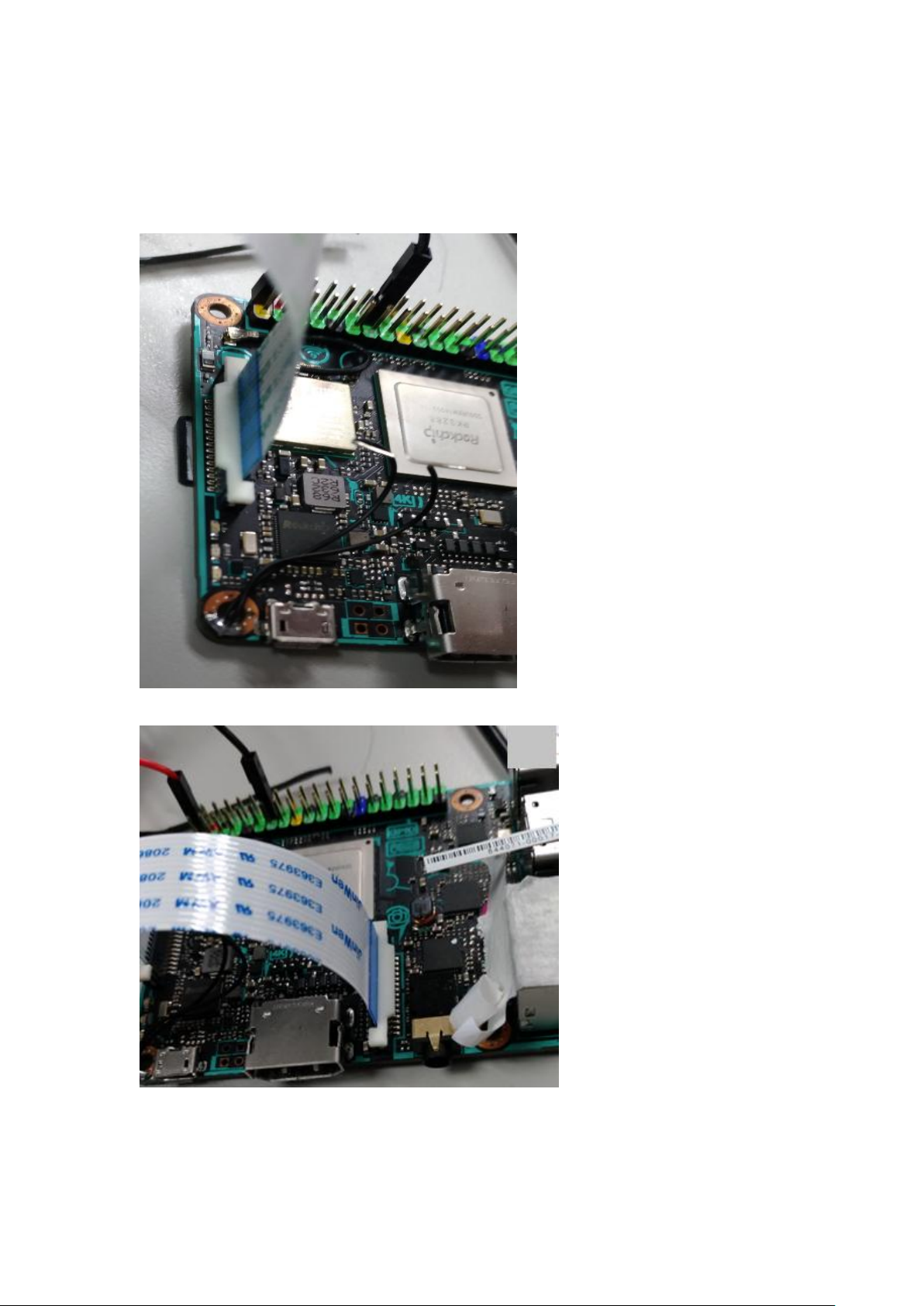
You need to notice the direction, when you install cable, the principle is: blue side is face
outside of the tinker board.
DSI:
CSI:
Page 3

Camera Operation SOP
Use Build-in Camera test tool for operation.
Some operations need root permission to execute.
Run “sudo su” in terminal command line before operation.
Camera Preview:
Key-in
camHalTest.bin 0
or
camHalTest.bin 1
0 for show preview in DSI
1 for show preview in HDMI
Camera preview will be showed on specific display equipment.
Capture
Each time executing Capture needs to run below cmd to setup environment.
sh /home/linaro/camera/copy_xml_file.sh
Then key-in capture cmd:
dumpsys
Five pictures will be taken and placed in /tmp/isptune with ppm filename extension.
Build-in file viewer is capable to open and view the image.
Note:
1. All contents in /tmp/ are volatile and will disappear after reboot.
2. Disk space for /tmp/ is only ~300MB and one ppm image size is ~22MB, so it can
only save ~12 pictures. Make sure to move (mv) image files to external storage
before next Capture operation of stress test.
Page 4
1. What is a Single Board Computer
A single-board computer (SBC) is a complete computer built on a single circuit
board, with microprocessor(s), memory, input/output (I/O) and other features
required of a functional computer. Single-board computers were made as
demonstration or development systems, for educational systems, or for use as
embedded computer controllers. Many types of home computers or portable
computers integrate all their functions onto a single printed circuit board.
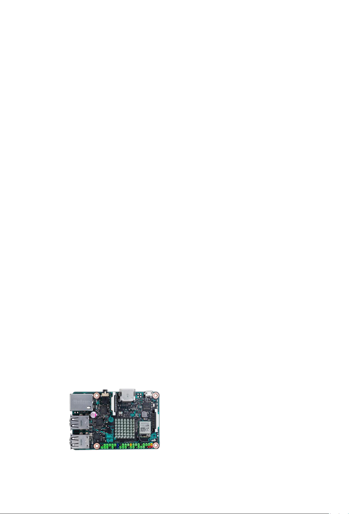
2. What is Tinkerboard
Tinker Board packs a whole load of exciting feature into a very small space, and
at an incredibly competitive price that’s barely more than its manufacturing cost.
ASUS has identified a clear DIY/maker market trend and we intend to create a big
impact with our little board, so we’ve crammed in loads of tech while keeping our
profits to a minimum — it’s our little contribution to the DIY world.
3. How powerful is the CPU processing
Tinker Board features a powerful quad-core ARM Cortex-A17 1.8Ghz processor
with a dual-channel DDR3 memory architecture. The performance is almost twice
faster than the Raspberry Pi 3, and much higher than most of the SBC boards. For
heavy computing loads like OpenCV projects, Tinker board should be one of
selected platform for your creation.
4. How powerful is the GPU processing
Tinker Board has an integrated ARM Mali GPU T760 MP4 supports up to up-
scaled 4K from 1080P, and the GPU also supports H.264/H.265 4K hardware
decoder for 4K content display.
5. Does the Tinkerboard overheat or need a heatsink
Since the performance is much higher than most of the SBC boards, the heat
generation is also higher. Thus Tinker Board will comes with a heatsink.
Page 5

6. What type of hardware interfaces does the Tinkerboard have
Tinker Board has 4 x USB 2.0 ports, 1 x GbE LAN, 1 x 3.5mm audio jack with
192K/24bit audio, MIPI DSI/CSI
7. Can I add additional system memory
The memory was soldered and mounted on the board during manufacturing, and
did fully test before shipping out. Even the SoC can supports for higher memory
capacity, but we’ll strongly recommend you do not swap the memory by yourself.
8. What Tinkerboard’s range of temperature operation
The operation temperature is between 30°C ~ 60°C based on system loading.
9. Can I connect a keyboard and mouse and use the Tinkerboard as a computer
/ PC
Yes, with the available operating system for Tinker Board, you can run Tinker
Board as a linux-based mini system for daily operation or enjoy the media content
thru this tiny board.
10. What are the Tinkerboard’s dimensions
Tinker Board measures 85.60mm x 56mm x 21mm (or roughly 3.37” x 2.21” x
0.83”).
11. How much does the Tinkerboard weigh
Tinker Board weighs 45g without installing the heatsink.
12. Is the Tinkerboard compatible with RasperryPI cases
Yes, Tinker Board can compatible with most of the chassis for Raspberry Pi.
13. What SoC are used in the Tinkerboard
The Tinker Board uses the Rockchip RK3288. This contains an quad-core ARM
cortex A17, running at 1.8Ghz, and a Mali T760 MP4 GPU.
14. What type of Wi-Fi does the Tinkerboard offer
The Wi-Fi solution is AW-NB177NF module, it contains a Realtek RTL8723BS IC,
supports the Wi-Fi 802.11 b/g/n, and Bluetooth 4.0 + EDR.
15. What type of Bluetooth does the Tinkerboard offer
Page 6

Bluetooth 4.0 with EDR
16. Is the Ethernet port / LAN shared with the USB
The Ethernet port is working individually.
17. What type of hardware decoding does the Tinkerboard offer
The GPU equipped H.264/H.265 hardware decoder for video contents.
18. Does the Tinkerboard support an IR blaster
Tinker Board didn’t equip IR transmitter, but Tinker Board has many GPIO
expansion pins allowing this kind of extension.
19. What is the power requirement for the Tinkerboard
Tinker Board supports 5V/1~2.5A power input, but since the SoC’s performance is
high, if the connected peripheral required huge power demand from the board, it
might cause the power supply issue.
Thus we strongly recommended to use the AC adaptor with 5V/2~2.5A power
rating, plus LPS marking.
20. Can the Tinkerboard being powered by a battery
Yes, if the battery can supports power output with at least 5V/1A.
21. How does the Tinkerboard boot
All the files necessary for booting are installed in a FAT32 partition of the SD card.
The Tinker Board has to have an SD card installed to boot from.
22. What OS does the Tinkerboard support
Currently Debian is the only available OS for Tinker Board.
23. Which LINUX runs on the Tinkerboard
TinkerOS (based on Debian)
24. What type of microSD cards are supported
The MicroSD slot was from a SDIO 3.0 signal, allowing the MicroSD card with
UHS-I speed. And we recommend using the card size at least 8GB.
25. What type of SD card is recommended
Page 7

The MicroSD slot was from a SDIO 3.0 signal, allowing the MicroSD card with
UHS-I
26. What resolutions are supported for the HDMI output
The maximum HDMI output supports up to 4K/30fps, up-scaled from 1080P.
27. What display outs are supported
There’re two display interfaces on Tinker Board, one is HDMI & the other is MIPI
DSI.
28. Is sound supported through HDMI
Yes, the sound output can be worked from HDMI or the 192K/24bit audio jack.
29. What type of audio in and audio out are supported.
The 3.5mm audio jack on Tinker Board can supports Mic-in and Line-out at the
same time.
30. Can I stream Netflix
Yes
31. Which HDMI version is supported
HDMI 1.4
32. IS CEC supported on the HDMI port
33. What is the DSI port
The Display Serial Interface (DSI) is a specification by the Mobile Industry
Processor Interface (MIPI) alliance, DSI is commonly targeted at LCD and similar
display technologies. It defines a serial bus and a communication protocol
between the host (source of the image data) and the device (destination of the
image data).
34. What model of LCD panel is compatible with the Tinkerboard
The DSI interface is refer to the most popular design from Raspberry Pi, that
allows users to connect the 7” display from Raspberry.
35. Does the Tinkerboard have a realtime clock feature ( RTC )
No, but there’re so many alternatives available on the market.
Page 8

36. What else will I need after I purchase a Tinkerboard
Get a keyboard, mouse, USB AC adaptor, a monitor with HDMI, and a micro SD
card with 8GB capacity. Then download the OS image from its website, and burn
into the micro SD card.
37. What is the warranty on the Tinkerboard
1 Year
38. Does the Tinkerboard support Expansion shields
Yes, the 40-pin GPIO equipped several signals for expansion. It will works with the
GPIO API.
39. Does the Tinkerboard support Arduino
Yes
 Loading...