


A
Assembly Procedure
Chapter
Assembly Procedure
Please follow the information provided in this section to perform the
complete assembly procedure of the EPAD TF700. Be sure to use
proper tools described before.
fter you have completed the previous chapter of complete disassembly, please follow
this chapter to assemble the EPAD TF700 back together. This chapter describes the
procedures of the complete EPAD TF700 assembly. In addition, in between
procedures, the detailed assembly procedure of individual modules will be provided for
your service needs.
The assembly procedure consists of the following steps:
EPAD
……
……
P1~P14
…………
◆
Speaker
◆
Battery
◆
Main Board Module
◆
SUB Board
◆
LCD Module
V1.0
3 - 1

E P A D
S P E A K E R
Assembly Procedure
Speaker
The illustrations below show how to assemble the speaker on the EPAD TF700.
Paste the antenna
1. Paste the GPS antenna and WIFI antenna on the cover.
2. Well done as below.
V1.0
3 - 2

Install the Vibrator
Assembly Procedure
3. Paste the Vibrator on the cover.
V1.0
3 - 3

Install the Speaker
Assembly Procedure
4. Paste the Vibrator on the cover.
5. Well done as below.
BACK
V1.0
3 - 4

E P A D
F P C
Assembly Procedure
Docking FPC
The illustrations below show how to assemble the Docking FPC on the EPAD TF700.
1. Paste the Docking FPC on the cover and 2 screws. iron unit back to Pad.
2. Remember press latch button down to paste iron unit on the cover and 4 screws..
3. Paste Minkey LED on the cover and 2 screws.
V1.0
3 - 5

Assembly Procedure
4. Paste Hall_IC_FPC on the cover
5. Well all done as below.
BACK
V1.0
3 - 6
E P A D
MNKEY
FPC
M A I N B O A R D
M O D U L E
Assembly Procedure
SUB board
The illustrations below show how to assemble the Main board Module on the EPAD TF600T
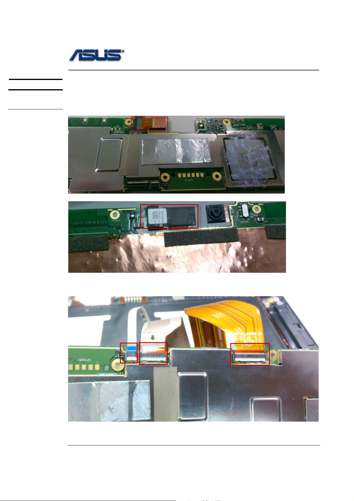
Assemble the SUB board module
1. Install the Camera to Sub Board.
2. Connect the 3 FPCS with the main board.
LCD FPC
Docking FPC
V1.0
3 - 7

Assembly Procedure
3. Paste SUB board on the cover.
4. Connecter plug to SUB board
V1.0
3 - 8

Assembly Procedure
5. Well all done as below. (Install the MIC rubber on the main board and 10 screws.)
BACK
V1.0
3 - 9

E P A D
L C D M O D U L E
Assembly Procedure
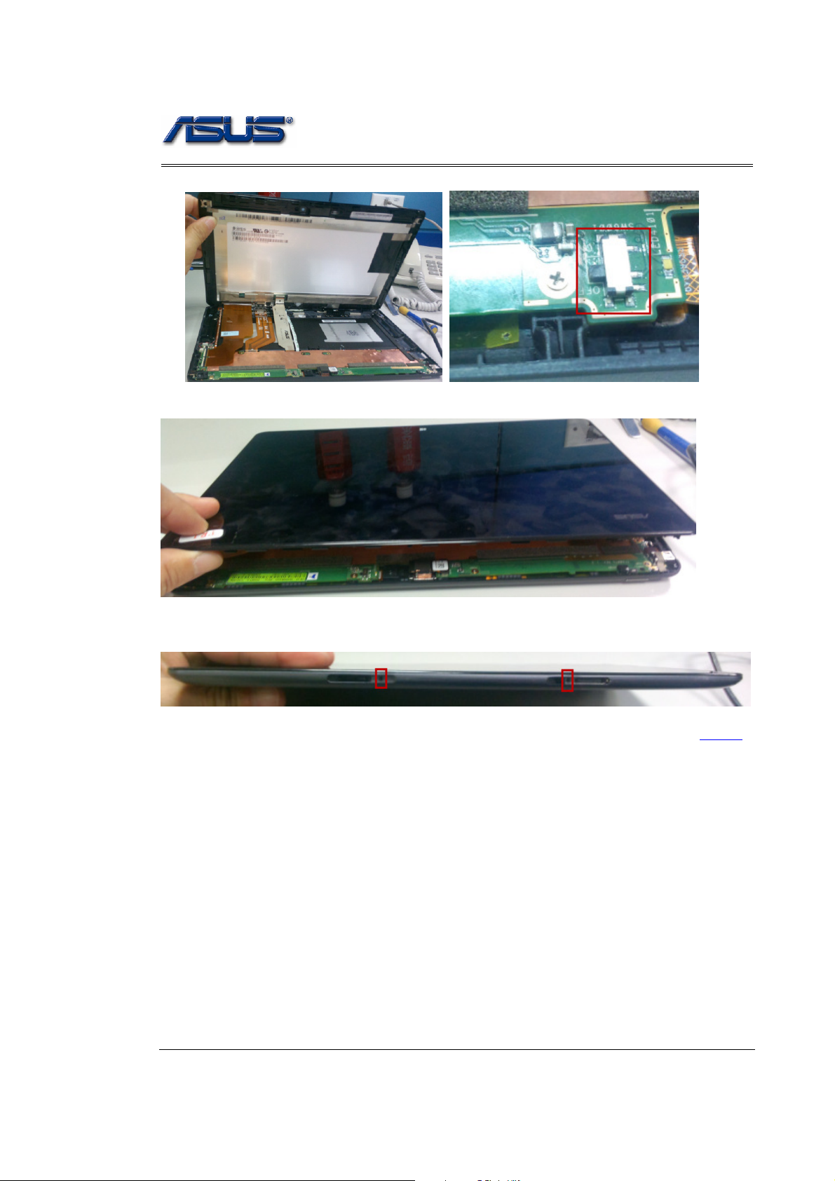
LCD Module
The illustrations below show how to assemble the LCD module on the EPAD TF600T.
1. Put the LCD module on the cover module.
2. Connect the TP FPC and LCD FPC.
V1.0
3 - 10
Assembly Procedure
3. Push the power button to turn on.
4. Install and lock the LCD module with cover.
5. Lift up and lock 2 LCD cover latch.
BACK
V1.0
3 - 11
 Loading...