

Page 1

2 - 1
A
Disassembly Procedure
Chapter
Disassembly Procedure
Please follow the information provided in this section to perform the complete
disassembly procedure of the EPAD TF600T. Be sure to use proper tools
described before.
SUS EPAD TF600T consists of various modules. This chapter describes the procedures for
the complete EPAD TF600T disassembly. In addition, in between procedures, the detailed
disassembly procedure of individual modules will be provided for your service needs.
The disassembly procedure consists of the following steps:
◆
Cover Module
◆
Battery
◆
TP Board
◆
DAU Board
◆
Main Board Module
◆
AUDIO_IO Board
◆
LCD Module
V1.0
Page 2

2 - 2
M O D U L E
Disassembly Procedure
L C D
LCD Module
The illustrations below show how to remove the Cover Module from the EPAD TF600T.
1. Remove 2 screws on the IO_DOCK.
2. Use disassembly tool to pry up the Panel Careful.
3. Life Up the LCD Module.
V1.0
Page 3

2 - 3
Disassembly Procedure
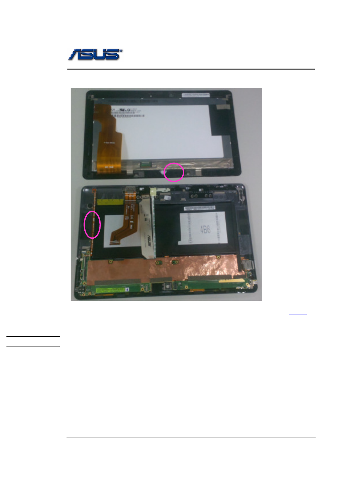
4. Push Power button to off.
5. Turn over the LCD Module and Open the White Latch to disconnect LCD FPC.
V1.0
Page 4
2 - 4
Disassembly Procedure
6. Take the LCD module away.
S U B B O A R D
BACK
Sub Board
The illustrations below show how to remove the Sub Board from the EPAD TF600T.
1. Unplug connecter.
V1.0
Page 5

2 - 5
Disassembly Procedure
2. Unplug FPC and Remove 10 Screws
V1.0
Page 6

2 - 6
Disassembly Procedure
3. Unplug FPC Connecter again.
C A M E R A
M O D U L E
4. Remove SUB board.
BACK
Camera Module
The illustrations below show how to remove the Camera Module from the EPAD TF600T.
1. Remove 2 Cameras form SUB Board.
V1.0
Page 7

2 - 7
Disassembly Procedure
2. Lift up to disconnect the camera module 8M. Than open the black latch to remove the
camera module 2M.
BACK
V1.0
Page 8

2 - 8
Disassembly Procedure
S P E A K E R
Speaker
The illustrations below show how to remove the Speaker from the EPAD TF600T.
1. Remove 4 Screw Away
Remover Vibrator
2. Disconnect the vibrator cable. Then tear off the vibrator from the cover
V1.0
Page 9

2 - 9
Disassembly Procedure
V1.0
Page 10

2 - 10
Disassembly Procedure
Remover Wifi and GPS
3. Tear off the GPS and Wifi antenna
Remover Docking / Hall / LED FPC
4. Plug Hall FPC away
V1.0
Page 11

2 - 11
5. Remove two screw on LED FPC
Disassembly Procedure
6. Remove 4 screws
Plug the latch button and take iron away
V1.0
Page 12

2 - 12
Disassembly Procedure
Remove two screws at docking FPC and take away
BACK
V1.0
 Loading...