

Page 1
®
Terminator P4 533A
Page 2
(1) 2
©2003
: Terminator P4 533A
: V3 T1271
: 2003 3
2
Page 3
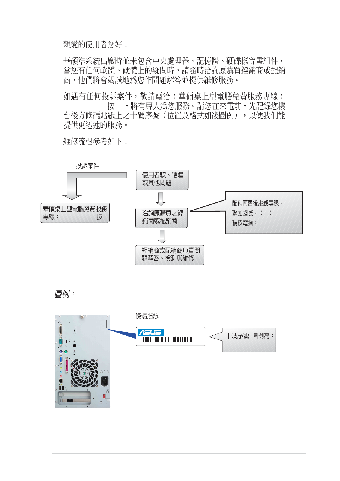
0800-093456 3
0800-093456 3
®
17PG010353
AS TERMINATOR B
B. TF2
02 2506-2558
0800-089558
17PG010353
3
Page 4
........................................................................................
2
1.1
1.2
1.3
........................................................................................
..........................................................................................................
....................................................................................................
............................................................................................
:
.............................................................
......................................................................................
..................................................................................................
..................................................
........................................................................
........................................................................
................................................................................
..................................................
3
4
7
8
9
10
10
11
12
13
14
15
2.1
2.2
2.3
2.4
2.4.1 CPU
2.5
2.6
2.7
2.8
2.9
2.9.1
2.9.2 UAEX
2.10
2.11
2.12
........................................................................................
CPU
PCI
.......................................................................................
........................................................................................
16
............................................................................
........................................................................
........................................................................
............................................................................
....................................................................................
....................................................................................
...........................................................................
................................................................
..........................................................................................
USB-CF
........................................................................
............................................................................
.......................................................
17
19
21
23
25
26
28
30
31
31
32
33
35
36
4
Page 5
...............................................
37
3.1 P4SC-EA
3.2
3.3
3.4
3.5
3.6
3.6
....................................................................................
...............................................................................
CPU
....................................................................................
............................................................................................
................................................................................................
3.7
3.8
........................................................................................
BIOS
4.1 BIOS
4.1.1
4.1.2 BIOS
4.2 BIOS
.............................................................................................
.......................................................................................
................................................................
....................................................................
....................................................................
................................................
55
.......................................................................
......................................................................
38
38
41
42
43
44
44
45
47
56
56
58
60
4.2.1 BIOS
4.2.2
4.3 Main Menu
4.3.1 Primary & Secondary Master/Slave
4.3.2 Keyboard Features
4.4 Advanced Menu
4.4.1 Chip Configuration
4.4.2 I/O Device Configuration
4.4.3 PCI Configuration
4.5 Power Menu
4.5.1 Power Up Control
5.5.2 Hardware Monitor
4.6 Boot Menu
4.7 Exit Menu
.........................................................................................
......................................................................................
.....................................................................
.........................................................
I/O
PCI
..................................................................
...............................................................
..................................................................
BIOS
........................................................
61
61
63
.........................................
.......................................................
65
69
70
...................................................
...............................................
72
74
76
79
........................................................
........................................................
81
83
85
87
5
Page 6
..................................................
89
5.1
5.2
5.3
5.3.1
5.3.2
................................................................................
........................................................................
........................................................................................
..................................................................................
......................................................................................
90
90
93
93
95
6
Page 7
1)
2)
3)
4) 1.44MB
5) CPU
6)
7)
8)
9) CD-ROM
10)56K PCI Modem Card
11) CPU
7
Page 8

IC
8
Page 9

Terminator
Terminator
Page 10
1.
2.
3.
4.
Terminator
step-by-step
Terminator
P4SC-EA
Jumper
USB/
10
5. BIOS
BIOS BIOS
6.
0
Page 11

Terminator
Page 12
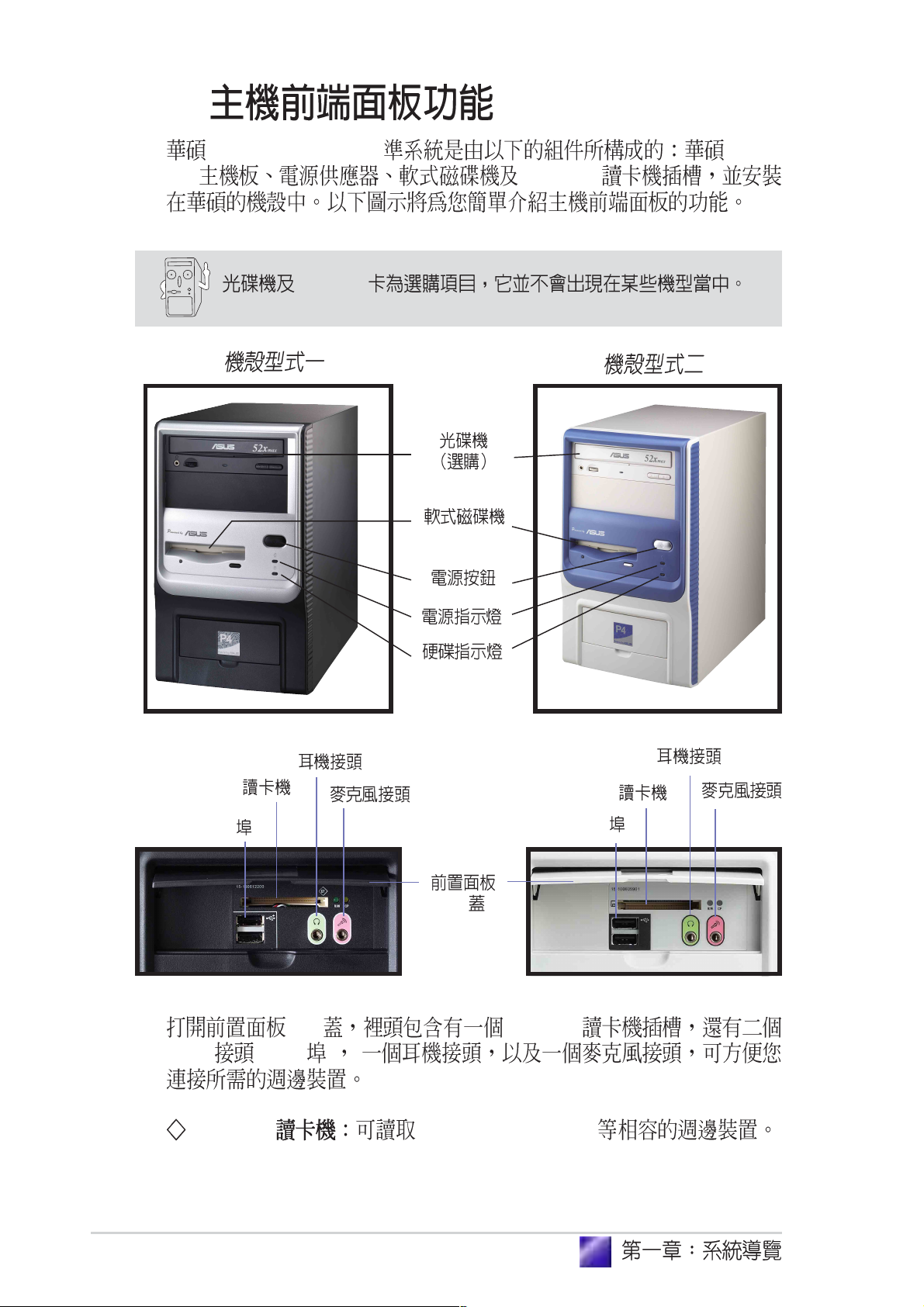
1.1
Terminator P4 533A P4SC-
EA CF Card
Modem
CF
USB
I/O
I/O CF Card
USB (2&3 )
CF Card Compact Flash Card
CF
USB
12
Page 13
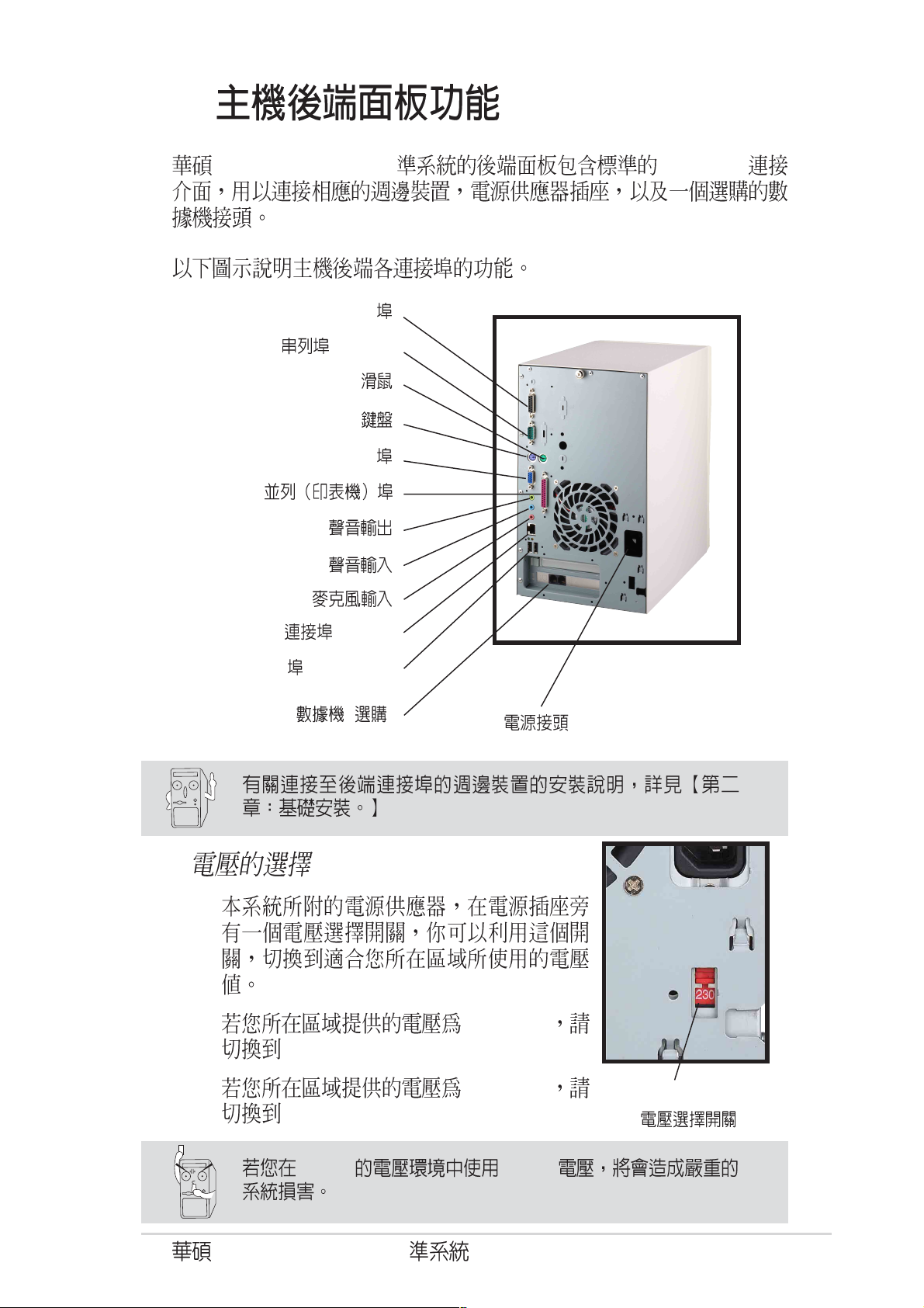
1.2
Terminator P4 533A PC99 I/O
Game/MIDI
(COM1)
PS/2
PS/2
VGA
LAN (RJ-45)
USB
(Ports 0&1)
( )
115V
100-127V
230V
230V 115V
Terminator P4 533A
200-240V
115V/230V
13
Page 14
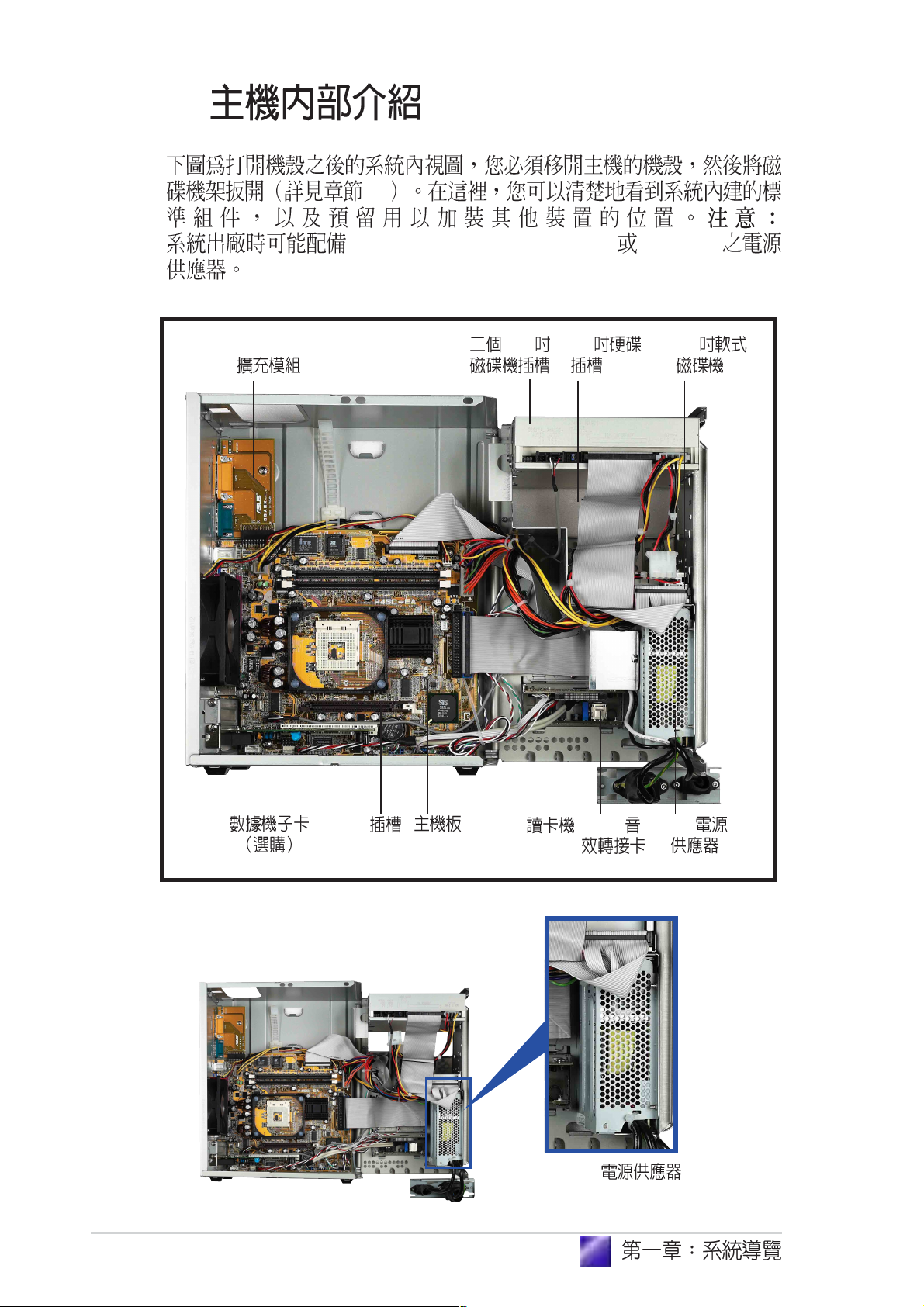
1.3
2.1
PFC (Power Factor Correction) non-PFC
5.25 3.5 3.5Game/MIDI/Com1
14
AGP
CF
Non-PFC
USB/
PFC
Page 15

step-by-step
Terminator
Page 16
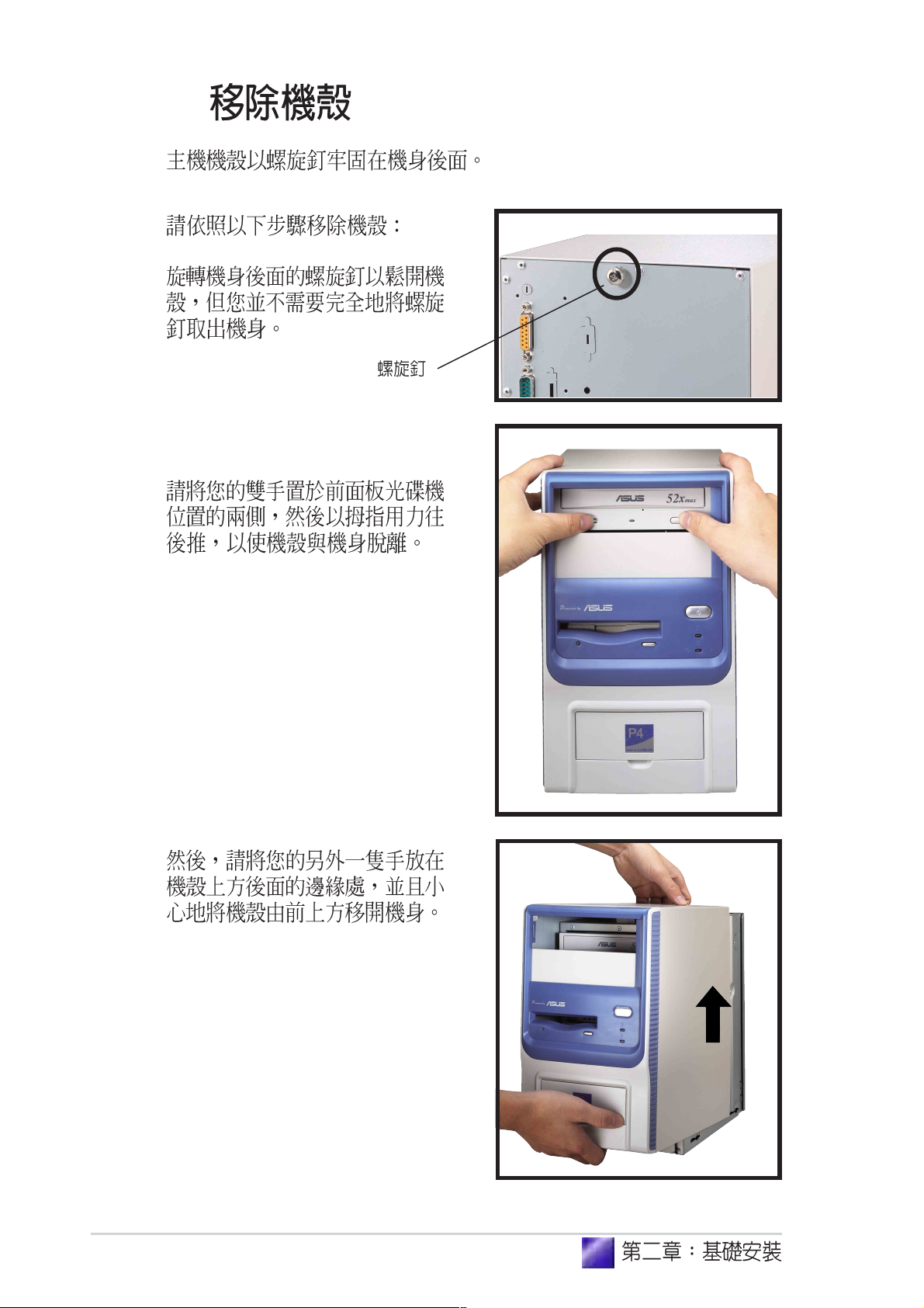
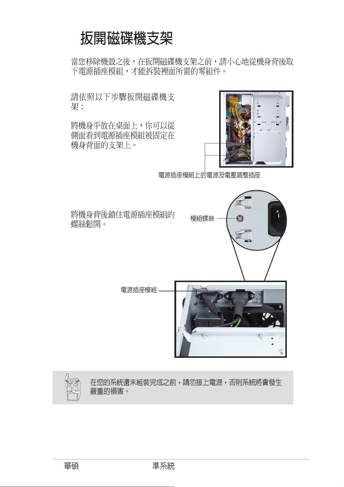
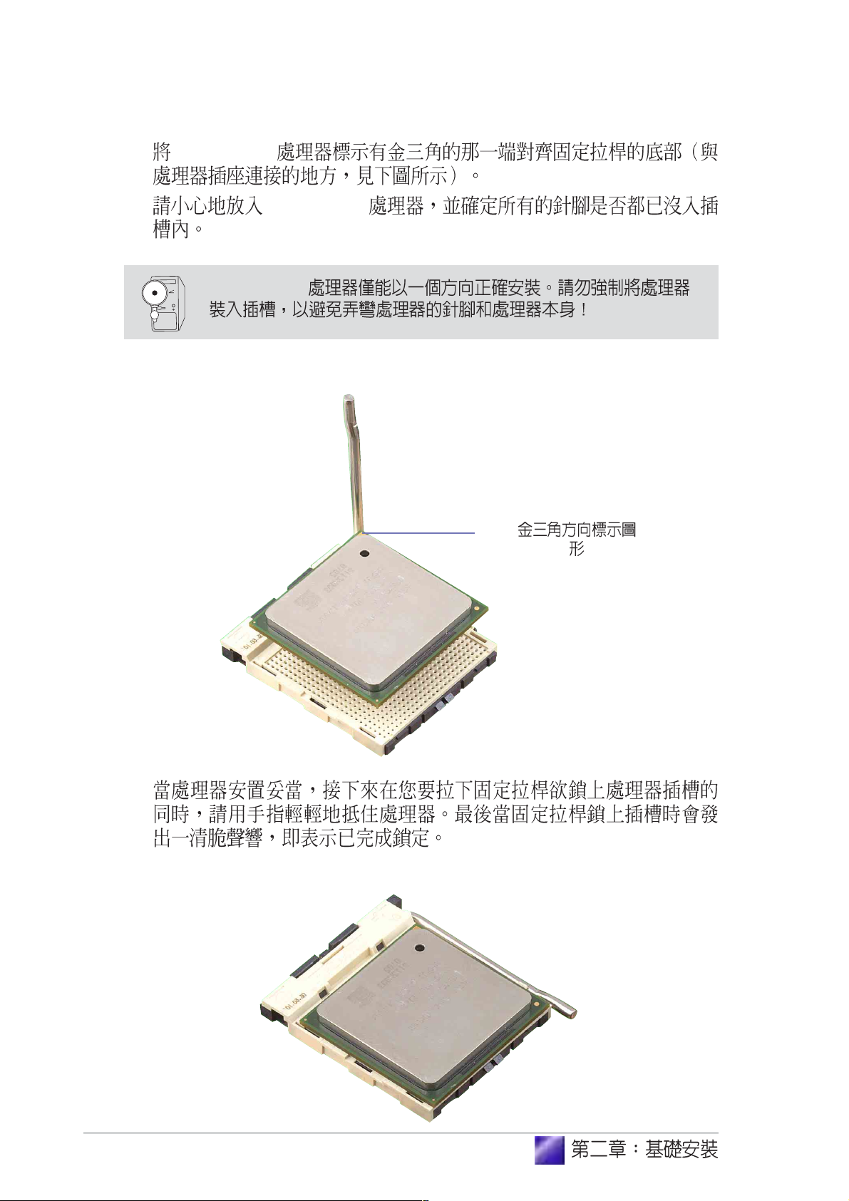
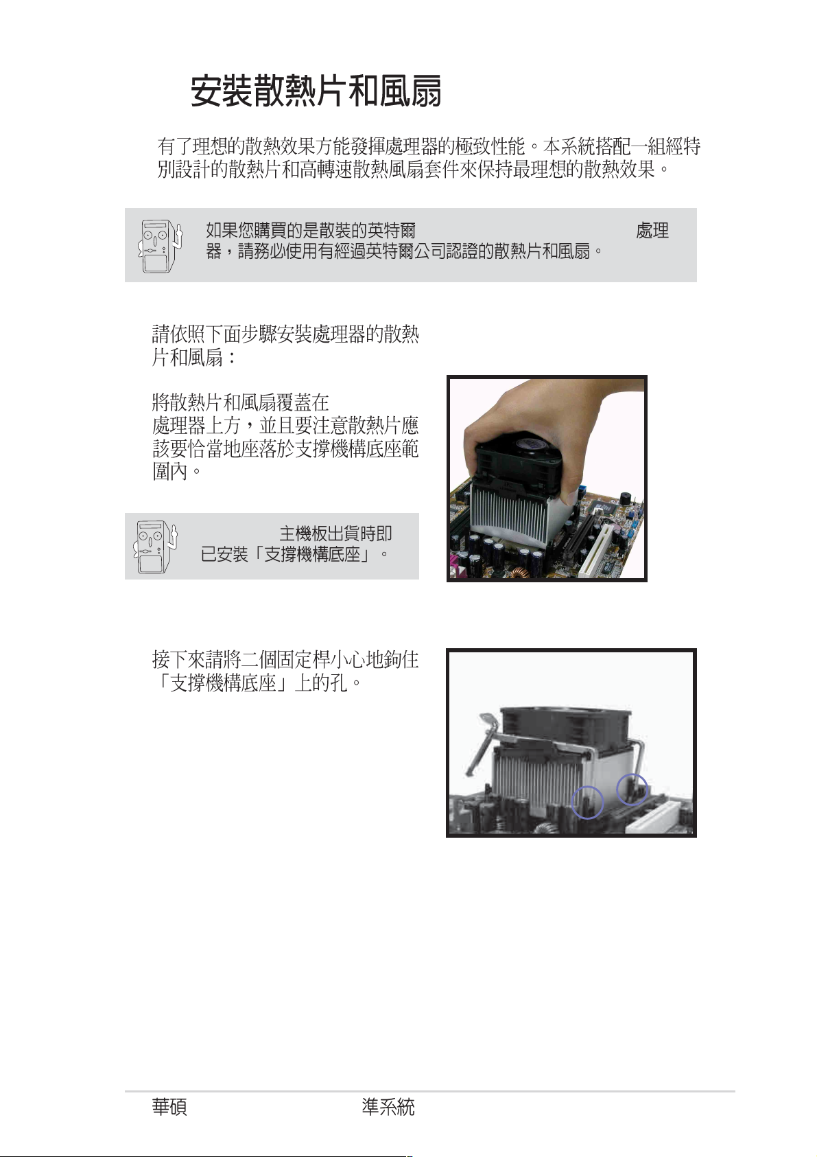
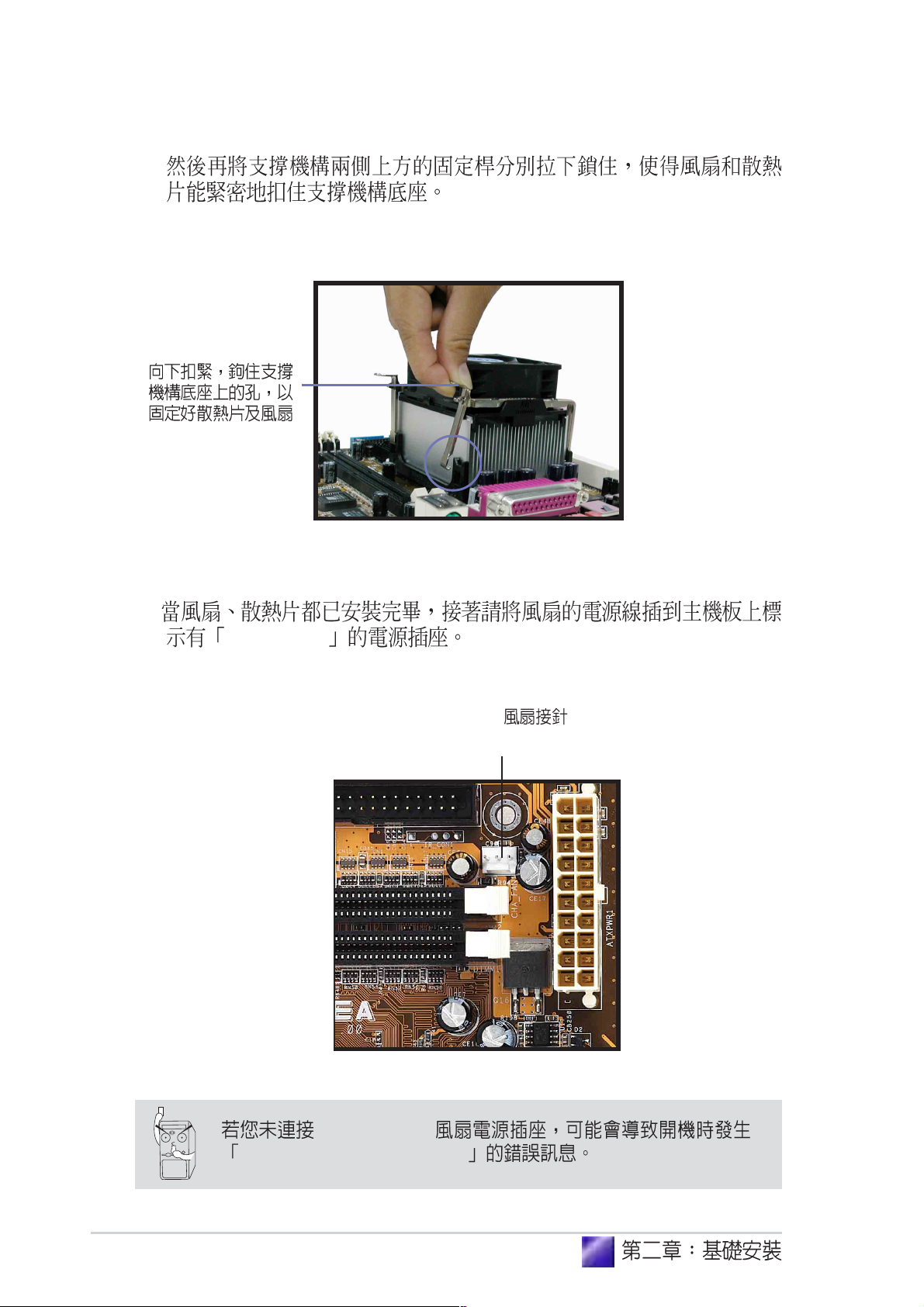
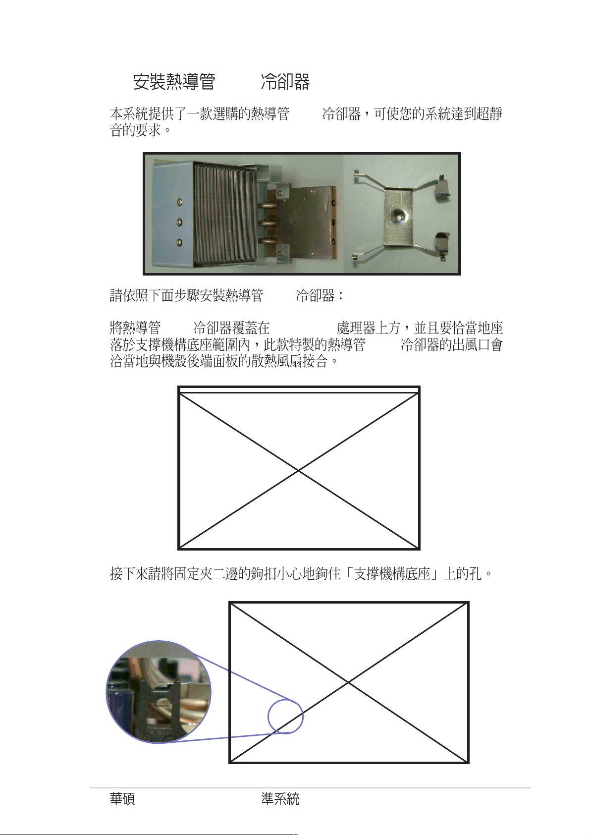
2.1
1.
2.
16
3.
Page 17
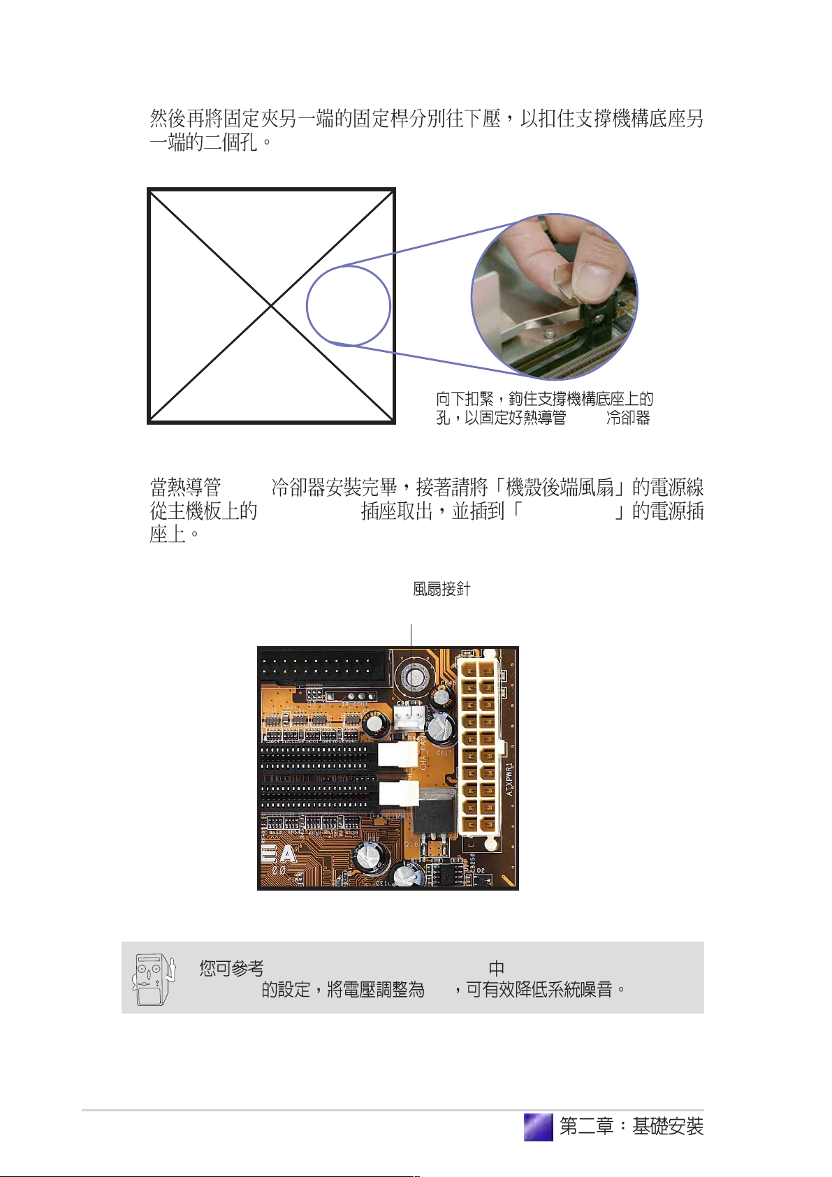
2.2
1.
2.
Terminator P4 533A
17
Page 18

3.
4.
18
5.
Page 19

2.3 CPU
0
P4SC-EA Socket 478 CPU
Intel Pentium 4
1. CPU
Socket 478
CPU
CPU
2. CPU
90-100
Socket-478
Pentium
90 -10
®
4
Terminator P4 533A
19
Page 20
®
3. Pentium
4
4. Pentium
®
4
Pentium
®
4
20
5.
Page 21
2.4
Pentium® 4 478/Northwood
1. Pentium
P4SC-EA
2.
®
4
Terminator P4 533A
21
Page 22
3.
4.
CPU_FAN1
CPU
(CPU_FAN1)
CPU_FAN1
Hardware monitoring errors
22
Page 23
2.4.1 CPU
CPU
CPU
1. CPU Pentium
2.
®
4
CPU
Terminator P4 533A
23
Page 24
3.
4. CPU
CHA_FAN1 CPU_FAN1
CPU
CPU
(CPU_FAN1)
BIOS 4.5.2 Hardware Monitor CPU Fan Lowest Level
Voltage 3V
24
Page 25
2.5
184-pin DDR DIMM Double Data Rate
unbuffered non-ECC PC2700/
2100/1600 DDR DIMM 2 GB
DDR DIMM
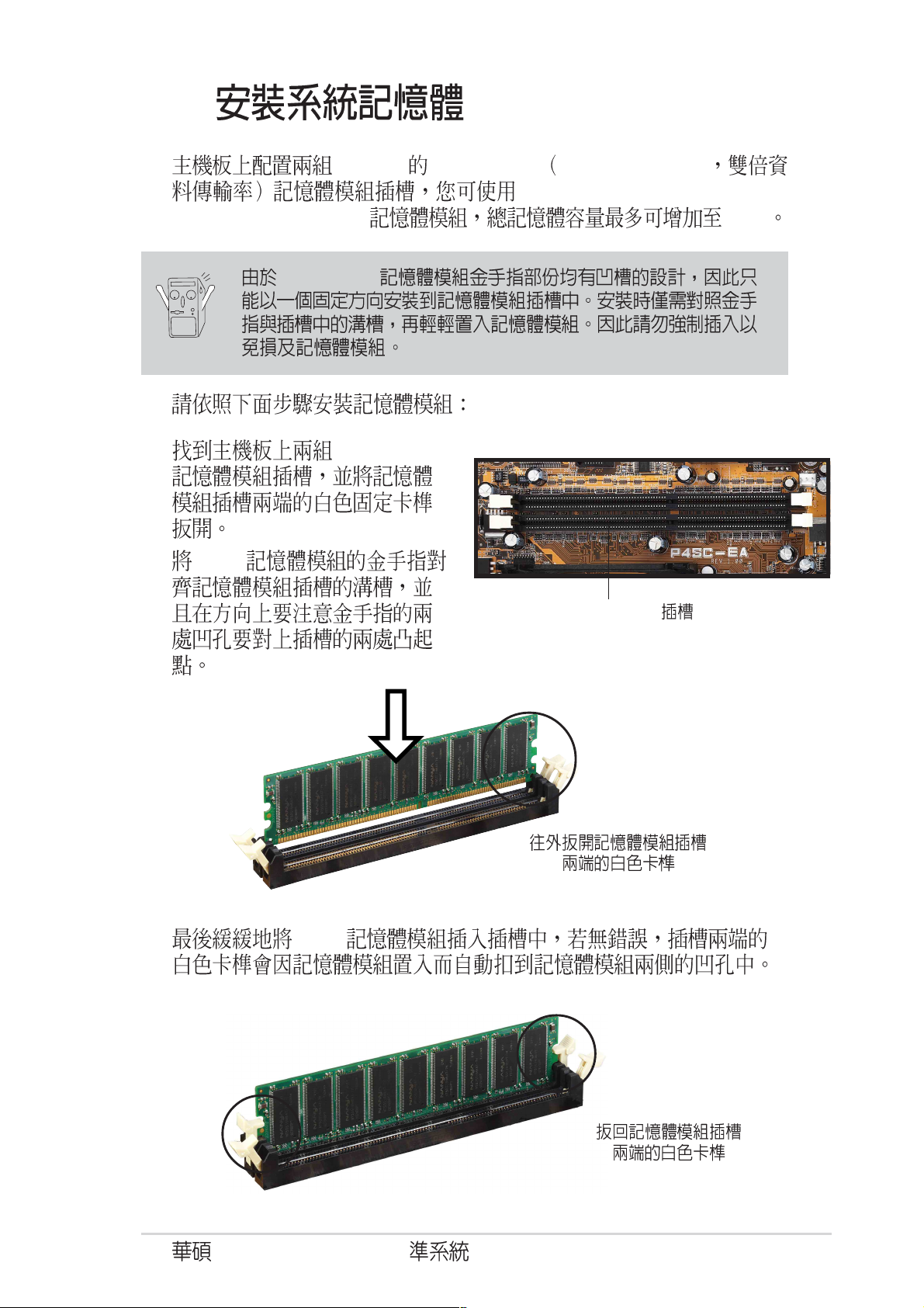
1. DDR DIMM
2. DDR
3. DDR
DDR DIMM
Terminator P4 533A
25
Page 26
2.6
3.5 (HDD) 5.25
5.25
3.5
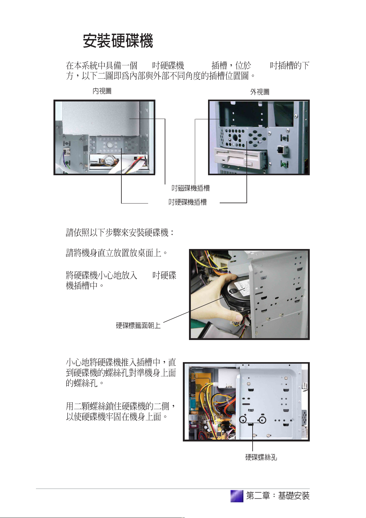
1.
2. 3.5
3.
4.
26
Page 27
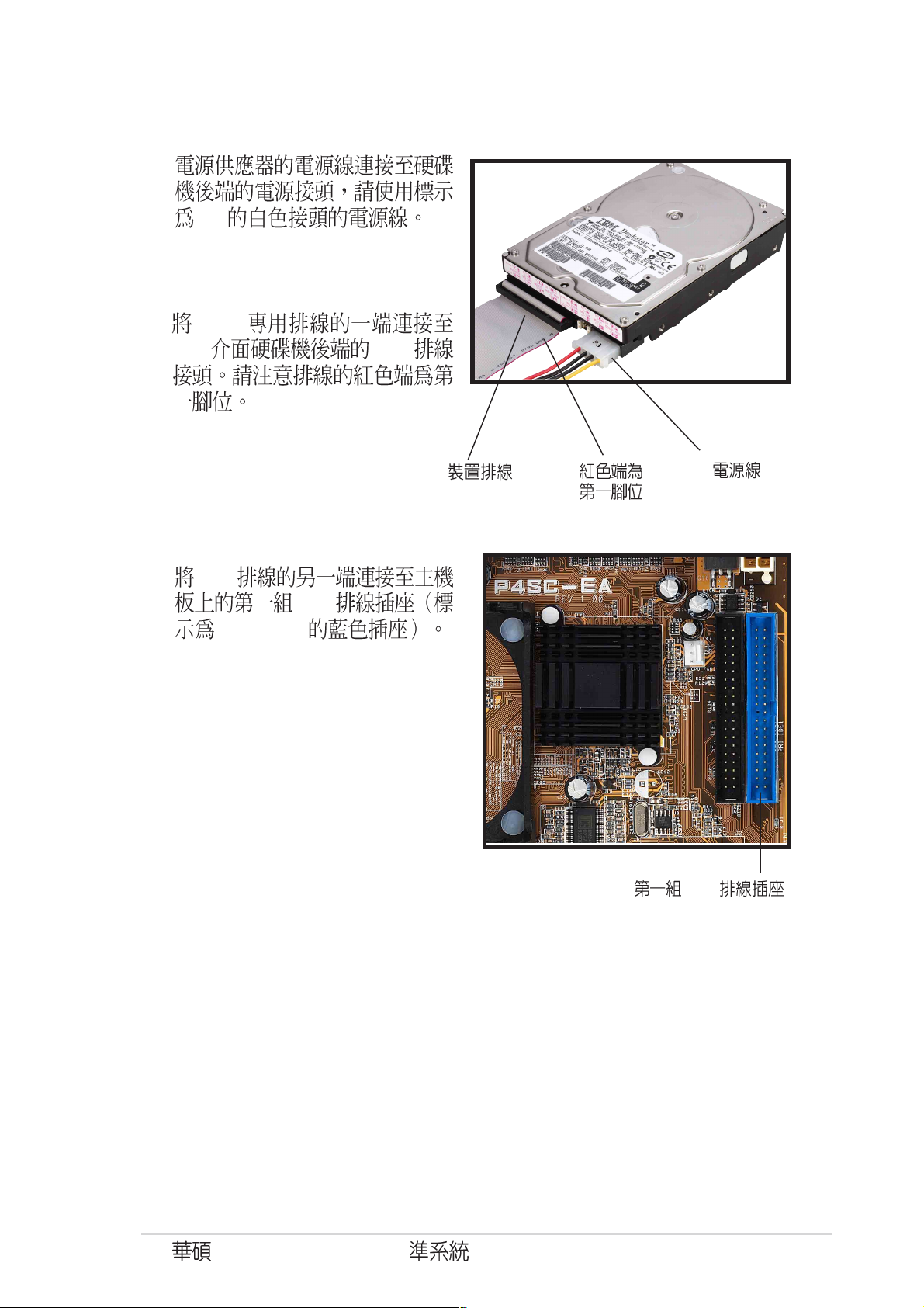
5.
P3
6. IDE
IDE IDE
7. IDE
PRI IDE1
IDE
IDE
(P3)
IDE
(PRI IDE1)
Terminator P4 533A
27
Page 28
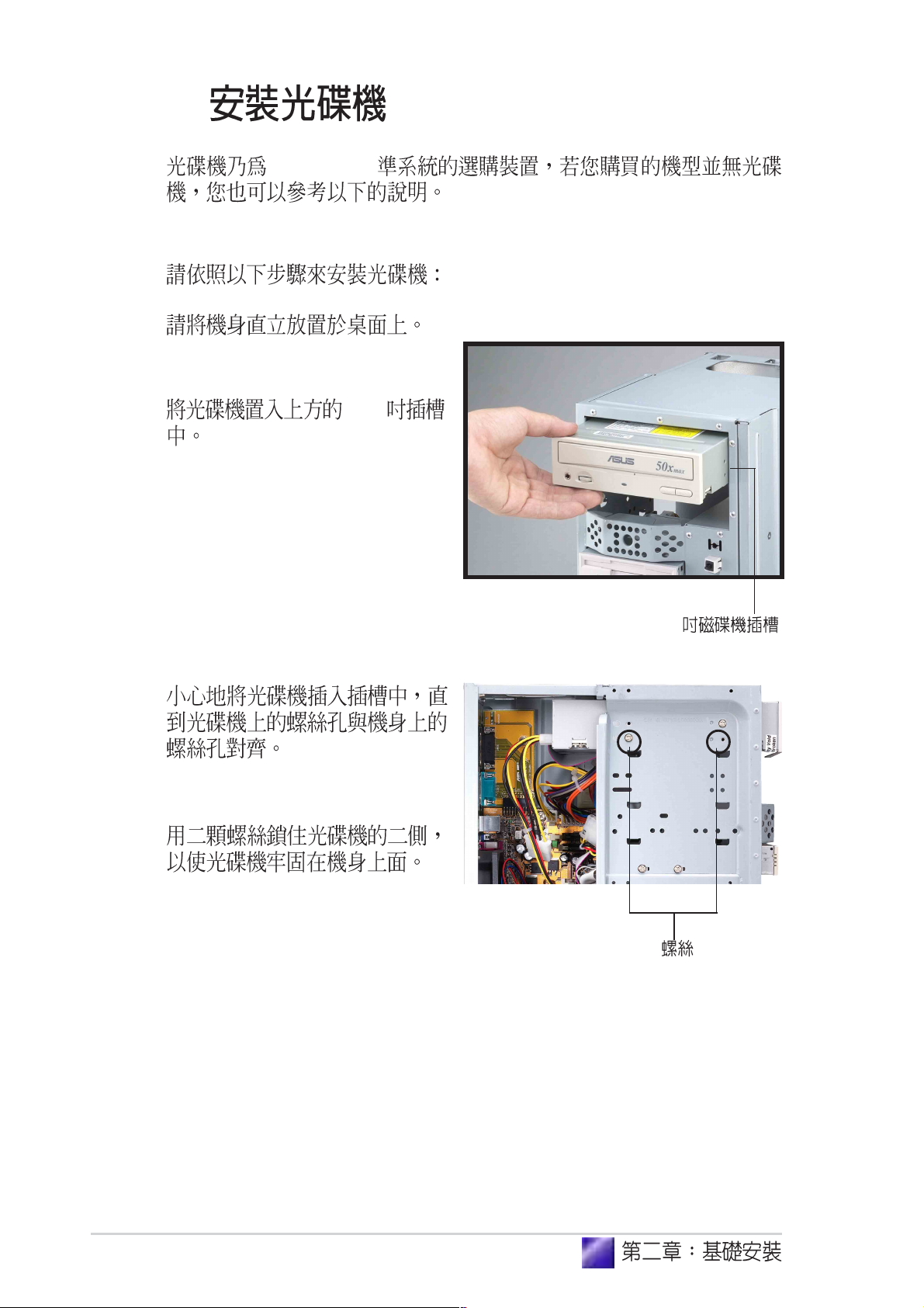
2.7
Terminator
1.
2. 5.25
3.
4.
5.25
28
Page 29
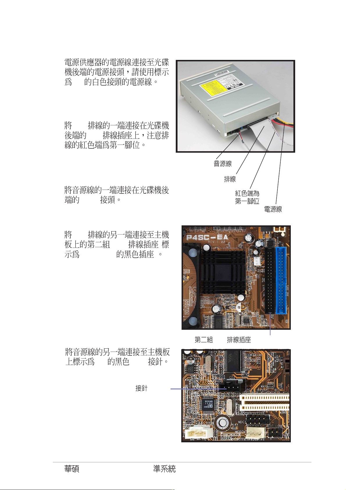
5.
P1
6. IDE
7.
4-pin
IDE
CD-ROM
IDE
(P1)
8. IDE
SEC IDE1 )
9.
IDE (
CD 4-pin
CD-ROM
IDE (SEC IDE1)
(CD1)
Terminator P4 533A
29
Page 30
2.8
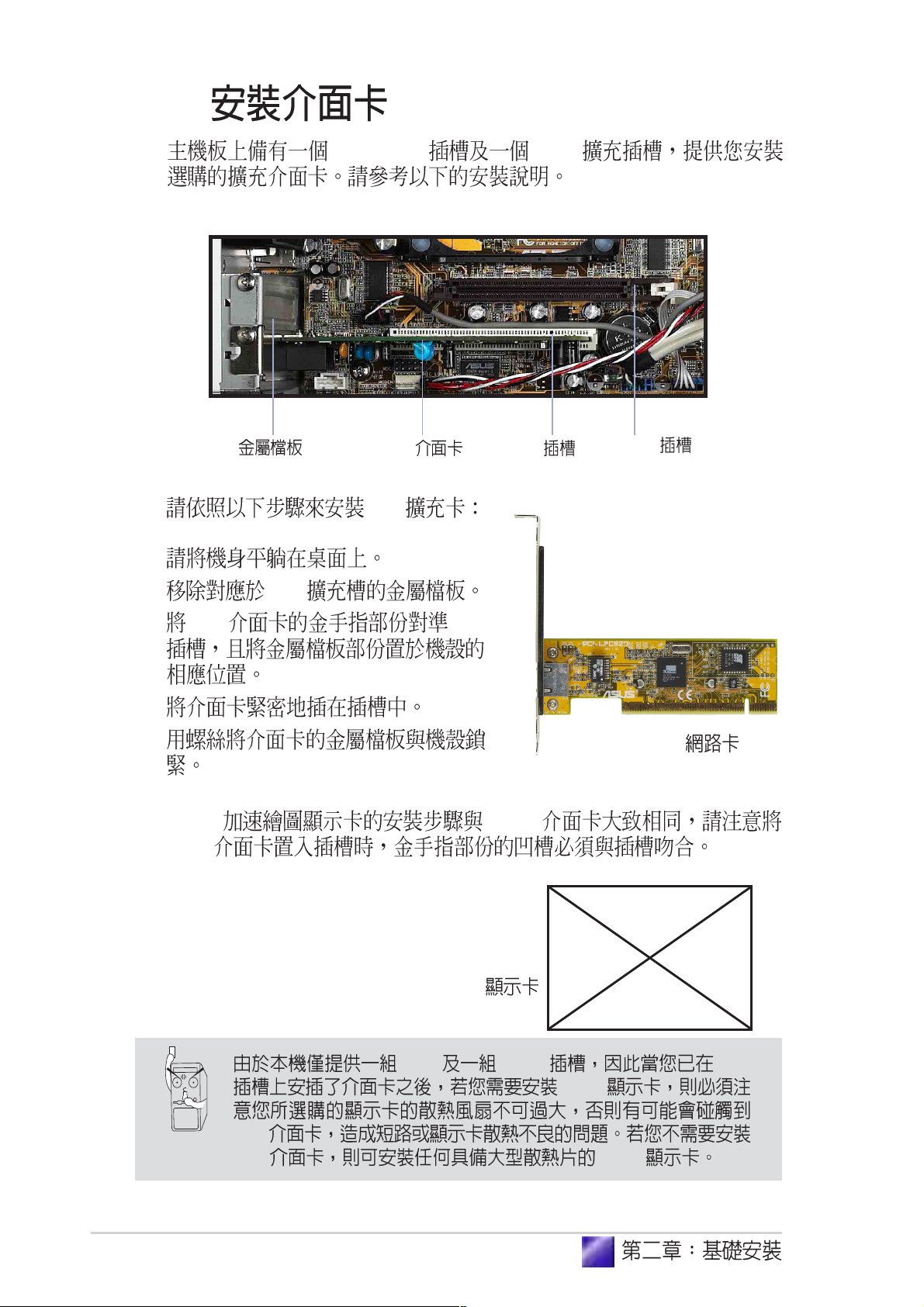
32-bit PCI AGP
PCI
1.
2. PCI
3. PCI PCI
4.
5.
AGP PCI
AGP
PCI PCI
AGP
PCI
30
AGP
PCI AGP PCI
AGP
PCI
PCI AGP
Page 31

2.9
2.9.1
PANEL1
Connector
Speaker
PLED
MLED
ExtSMI#
Connector
Ground
+5V
PWR
Ground
Ground
Speaker
Ground
Reset
Ground
Power LED
+5VSB
+5 V
Reset SW
Message LED
ATX Power
PANEL1
SMI Lead
*
Requires an ATX power supply.
Switch*
IDE_LED1
1. Power Switch Power LED
PANEL1
2. HDD LED IDE_LED1 2-pin
Terminator P4 533A
31
Page 32

2.9.2 UAEX
®
2
UAEX
USB-CF
MIC
LO2
MIC
MIC_LOUT1
USB_CF
®
LOUT
CON1
UAEX
LED3 LED2
J1
T: Port0
B: Port1
USB2P
USB
USB_34
USB_34
USB_56
USB_56
MIC_LOUT1
( Line Out )
32
Page 33

2.10
1.
2.
3.
4.
2
Terminator P4 533A
33
Page 34

5.
6.
34
7.
Page 35

2.11
Game/
MIDI
PS/2
VGA
RJ-45
PS/2
USB
Terminator P4 533A
35
Page 36

2.12
1 90V 115V 135V
2 180V 230V 265V
47 Hz to 63 Hz
AC 4A max at 115Vac
2A max. at 230Vac, maximum load
90A max. at 115Vac,
full load cold start at 25
70% min. at nominal input,
maximum load
Load Range Regulation Ripple
+5V 0.5A 4.0A -5% +5% 50mV
+12V 0.45A 9.5A -5% +5% 120mV
-12V 0A 0.2A -10% +10% 120mV
+5Vsb 0.05A 1.5A -5% +5% 50mV
+3V3 1A 8.0A -5% +5% 50mV
Over-Voltage Protection (OVP)
+5V 6.5V
+12V 15.6V
+3.3V 4.3V
p-p
p-p
p-p
p-p
p-p
36
+5V +12V -12V +3.3V
+5Vsb
Page 37

P4SC-EA
Jumper
BIOS
( )
<Del>
BIOS
Page 38

3.1 P4SC-EA
16 17
21 3 64 5 7
9
8
P4SC-EA
3.2
1115 1013 1214
38
2325 24 1822 21 20 19
Page 39

12 - 12V 4 Pin
1
Super I/O
2
UART SIR /
Flash ROM -
3
4
400MHz Pentium® 4 478/Northwood
3.06GHz+
DDR - 184 DDR DIMM
5
unbuffered non-ECC DDR SDRAM 2 GB
-
(Smart Card Reader)
360K/720K/1.44M/2.88M
2Mb
BIOS
- 478 ZIF Zero Insertion Force
mPGA478 533/
PC2700/PC2100/PC1600
6
7
8
9
10
- 3.5
- 12V
+5VSB
1
- Pentium® 4
SiS651 AGP (MuTIOL Multi-
threaded I/O Link) 533 MB
IDE - IDE
Ultra DMA/133/100/66 PIO 3/4 IDE
IDE
- SiS962L MuTIOL
AC97 MAC USB
IDE Master/Slave (MuTIOL Multi-
threaded I/O Link) 533 MB
Terminator P4 533A
39
Page 40

11
AGP
- AGP 3D
AGP 4X
12
13
14
15
16
17
18
ASIC - ASIC
IRQ
PCI
PCI SCSI
133MB PCI
- VIA VT6103 10Base-T/
100Base-TX
Modem - AC97
PS/2
-
USB 2.0
Bus PDA
USB 2.0
- USB 2.0 Unervisal Serial
- 32 PCI 2.2
- PS/2
19
20
21
22
23
24
25
- LED
RJ-45 - (
)
- (
)
-
( )
- (
)
- 15-pin
PS/2 - PS/2
40
Page 41

23cm (9.06in)
®
3.3
PS/2
VGA1
RJ-45
USB
USB2
USB1
LANLED
IOC_MB
ATX12V1
USBPWR_12
Audio
Codec
MODEM1
CD1
LAN
CHIP
AUX1
MDC1
Super
I/O
MIC_LOUT1
Flash
BIOS
DDR DIMM
DDR DIMM
Socket 478
CPU
AGP
PCI
ASUS
Mozart
P4SC-EA
USBPWR_34
FLOPPY1
(64/72-bit, 184-pin)
(64/72-bit, 184-pin)
SiS
651
CR2030 3V
CMOS
USBPWR_56
USB_34
CHA_FAN1
USB_56
962L
CLRTC1
CPU_FAN1
IDE
SiS
UA
BUZZER1
IDE_LED1
SEC_IDE1
IDE
PANEL1
22.4cm (8.82in)
PRI_IDE1
Terminator P4 533A
41
Page 42

3.4 (CPU)
®
478 ZIF
Socket-478 Pentium® 4 478/
Northwood
P4SC-EA
Gold Arrow
P4SC-EA Socket 478
Socket-478 Pentium® 4 FC-PGA2 Flip-Chip Pin Grid
Array 2 Intel® NetBurstTM
Pentium® 4
533/400MHz execution trace cache
20
3.2 GB Pentium® 4
P4SC-EA
Hyper-Threading
1. Hyper-Threading Intel® Pentium® 4
2. Hyper-Threading Windows XP
BIOS Hyper-
Threading
3. WindowsXP Service Pack 1
4. BIOS Hyper-Threading Technology
Enabled Hyper-Threading
CPU
5. Http://www.intel.com/info/hyperthreading
42
Page 43

3.5
®
P4SC-EA 184 DDR DIMM Double Data
Rate unbuffered nonECC PC2700/2100/1600 DDR DIMM
2 GB
P4SC-EA
P4SC-EA 184-Pin DDR DIMM Sockets
64, 128, 256, 512MB 1GB DDR DIMM
DIMM 184-pin DDR
Socket 1 (Rows 0&1) 64MB, 128MB, 25 6MB, 512MB, 1GBx1
Socket 2 (Rows 2&3) 64MB, 128MB, 25 6MB, 512MB, 1GBx1
( 2 GB) =
80 Pins104 Pins
184 DDR DIMM 164 SDR DIMM
DDR DIMM
SDR DIMM DDR DIMM
SDR DIMM
2.5
Terminator P4 533A
43
Page 44

3.6
PCI AGP PCI
AGP 2.8
3.6.1
1. BIOS
BIOS
2. IRQ
3.
IRQ
01
12
2 N/A
3* 11 COM 2
4* 12 COM 1
5* 13
614
7* 15 LPT 1
83 CMOS/
9* 4 ACPI
10* 5 PCI
11* 6 PCI
12* 7 PS/2
13 8
14* 9 IDE
15* 10 IDE
*
( LPT2)
44
ABCDEFGH
PCI - ----- PCI -- -----
----- --
------ -
Page 45

3.7
®
1. USB 3-pin USB_PWR12, USB_PWR34,
USB_PWR56
+5V USB S1
(CPU DRAM
) +5VSB USB S3
( CPU DRAM
)
USB_PWR12 USB
USB_PWR34 USB_PWR56 USB
USB CF
1. USB +5VSB
1A/+5VSB
2.
P4SC-EA
P4SC-EA USB Device Wake Up
+5VSB
USBPWR_12
USBPWR_34
USBPWR_56
1
22
3
(Default)
12
+5V
(Default)
12
+5V
(Default)
+5VSB+5V
23
+5VSB
23
+5VSB
Terminator P4 533A
45
Page 46

2.BIOS Clear RTC RAM CLR_RTC
®
CMOS
CMOS
1
2
3 CLRTC [2-3] CMOS
4 CLRTC [1-2]
5
6 <Del> BIOS
BIOS
P4SC-EA
P4SC-EA Clear RTC RAM
2
1
Normal
(Default)
CLRTC1
3
2
Clear CMOS
46
Page 47

3.8
®
s
r
1. IDE 40-1 pin IDE1, IDE2
IDE IDE
IDE ( CD-ROM )
IDE
Master Slave
Primary Secondary IDE
UltraDMA/133/100/66 Slave
UltraDMA/133/100/66 Master UltraDMA/133/100/66
Secondary IDE
IDE
BIOS 6.6
UltraDMA100/UltraDMA66
UltraDMA100/UltraDMA66
Slave
20
P4SC-EA
P4SC-EA IDE Connectors
NOTE: Orient the red marking
(usually zigzag) on the IDE
ribbon cable to PIN 1.
Secondary IDE Connecto
PIN 1
Primary IDE Connector
Terminator P4 533A
47
Page 48

2. 34-1 pin FLOPPY1
®
n
®
t
P4SC-EA
PIN 1
NOTE: Orient the red markings o
the floppy ribbon cable to PIN 1.
P4SC-EA Floppy Disk Drive Connector
FLOPPY1
3. IDE 2-pin IDE_LED1
IDE IDE
IDE
IDE
P4SC-EA
TIP: If the case-mounted LED does no
IDE
light, try reversing the 2-pin plug.
IDE_LED1
P4SC-EA IDE Activity LED
48
Page 49

4. (20-pin ATXPWR, 4-pin ATX +12V)
®
n
ATX +12V
20 ATXPWR
Pentium
®
4 +12V
ATXPWR1
P4SC-EA
+12.0Volts
+5V Standby
Power Good
+5.0 Volts
+5.0 Volts
+3.3 Volts
+3.3 Volts
P4SC-EA ATX Power Connector
1. Pentium® 4
+12V
Ground
Ground
Ground
ATX12V1
+5.0 Volts
+5.0 Volts
-5.0 Volts
Ground
Ground
Ground
Power Supply O
Ground
-12.0Volts
+3.3Volts
+12V DCCOM
+12V DCCOM
2. +12V 8
+5VSB 1
230
300
Terminator P4 533A
49
Page 50

5. / / (3-pin CPU_FAN1,
®
n
CHA_FAN1)
350mA 4.2 12
RPM Rotations Per
Minute
CPU
CPU jumpers
jumper
Rotation
P4SC-EA
P4SC-EA 12-Volt Cooling Fan Power
CHA_FAN1
CPU_FAN1
GND
Rotation
+12V
GND
+12V
Rotatio
50
Page 51

6. USB 2.0 (10-1 pin USB_34,USB_56)
®
)
®
0
USB_34
USB2.0 USB_56( 6 10 )
USB_CF J1 USB_CF Compact Flash
P4SC-EA USB Ports
CF
P4SC-EA
UAEX USB2P
USB Power
USBP2–
USBP2+
GND
GND
USBP3–
USBP3+
NC
15
USB_34 USB_56
610
USB Power
USB Power
USBP2–
USBP2+
GND
15
61
NC
GND
USBP3–
USBP3+
USB Power
7. (4-pin AUX1, CD1, MODEM1)
CD-ROM
MPEG MODEM
CD1(Black)
P4SC-EA
AUX1(White)
Right Audio Channel
Ground
Left Audio Channel
P4SC-EA Internal Audio Connectors
Left Audio Channel
Ground
Right Audio Channel
Modem-In
(to Modem)
Ground
Modem-Out
(from Modem
MODEM1
Terminator P4 533A
51
Page 52

®
®
8. (5-1 pin MIC_LOUT1)
®
l
MIC_LOUT1
P4SC-EA
P4SC-EA Microphone Header
Head set Left channe
GNDHead set Right channel
1
1
MIC SignalMIC PWR
9. IO (22-pin IOC_MB)
CGAEX
P4SC-EA
COM1
P4SC-EA IOC_MB Connector
CGAEX
IOC_DC
GAME
52
Page 53

10. (20-pin PANEL1)
®
20-pin
Power LED
Speaker
Connector
P4SC-EA
P4SC-EA System Panel Connectors
(3-1 pin PLED)
(4-pin SPEAKER)
4-pin
(2-pin MLED)
Ground
+5VSB
+5 V
PLED
MLED
Ground
ExtSMI#
PWR
+5V
Ground
Speaker
Ground
Reset
Ground
Reset SW
Message LED
ATX Power
SMI Lead
* Requires an ATX power supply.
Switch*
SMI (2-pin SMI)
Turbo BIOS
Power Menu Suspend Mode
ACPI
/ (2-pin PWR)
Windows 98
CPU clock
Terminator P4 533A
53
Page 54

Reset
(2-pin RESET)
54
Page 55

BIOS
BIOS
BIOS
( )
<Del>
BIOS
Page 56

4.1 BIOS
4.1.1
AFLASH.EXE BIOS BIOS
BIOS BIOS
AFLASH.EXE
BIOS
BIOS
DOS
AFLASH DOS Winodws MSDOS BIOS
AFLASH
1. DOS FORMAT A:/S
AUTOEXEC.BAT
CONFIG.SYS
2. DOS COPY D:\AFLASH\AFLASH.EXE A:\
D AFLASH.EXE
3.
BIOS
56
BIOS
Page 57

4. DOS A:\AFLASH Enter AFLASH
Flash Memory unknown
ACPI BIOS
BIOS
5. 1. Save Current BIOS to File Enter
Save Current BIOS To File
6. A:\XXX-XX.
XXX Enter
Terminator P4 533A
57
Page 58

4.1.2 BIOS
BIOS
BIOS
BIOS
1. ( WWW FTP) BIOS
3
2.
3. A:\ AFLASH.EXE
4. MAIN MENU 2 Update BIOS Including Boot Block and
ESCD
5. Update BIOS Including Boot Block and ESCD
BIOS A:\XXX-XX.XXX
Enter
6. Y
58
BIOS
Page 59

7. AFLASH BIOS BIOS
Flashed Successfully
8. BIOS
BIOS
BIOS
Terminator P4 533A
59
Page 60

4.2 BIOS
BIOS Basic Input and Output System
BIOS
BIOS
BIOS
RUN SETUP BIOS
BIOS
EEPROM Electrical Erasable Programmable
Read-Only Memory BIOS EEPROM
BIOS BIOS
BIOS
CMOS RAM
BIOS
POST Power-On Self Test
DELETE
DELETE
RESET ALT - CTRL - DEL
BIOS
60
BIOS
BIOS
BIOS
Page 61

4.2.1 BIOS
BIOS
MAIN
ADVANCED BIOS
POWER
BOOT
EXIT BIOS
4.2.2
BIOS
<F1> or <Alt + H>
<Esc> or<Alt + X>
or → (keypad arrow)
←
↑ or ↓ (keypad arrows)
- (minus key)
+ (plus key) or spacebar
<Enter>
<Home> or <PgUp>
<End> or <PgDn>
<F5>
<F10>
Exit
BIOS
Terminator P4 533A
61
Page 62

F1 Alt + H
PgUp PgDn
Home
End Enter
Esc
Enter
ESC
BIOS
BIOS
BIOS F5
BIOS
5.7 BIOS
1. BIOS
BIOS
2. [ ] BIOS
BIOS
62
BIOS
Page 63

4.3 Main Menu
BIOS
System Time [XX:XX:XX]
00 23 00 59 00 59 Tab
Tab + Shift
System Date [XX/XX/XXXX]
1 12 1 31 00 99 Tab
Tab + Shift
Legacy Diskette A [1.44M, 3.5 in.]
[360K 5.25 in.] [1.
2M 5.25 in.] [720K 3.5 in.] [1.44M 3.5 in,] [2.88M 3.5 in.][None]
Floppy 3 Mode Support [Disabled]
1.2MB 3.5
[Disabled] [Enabled] [Drive B] [Both]
Terminator P4 533A
63
Page 64

Supervisor Password [Disabled] / User Password
[Disabled]
Enter
Enter 8
Enter
Enter BIOS
Enter
Enter
BIOS BIOS
BIOS Supervisor
password User password
BIOS
Supervisor
BIOS
?
RTC
RTC
Halt On [All Errors]
[All Errors] [No Error] [All but Keyboard] [All but Disk] [All but
Disk/Key]
Installed Memory [XXX MB]
CMOS
2.7
64
BIOS
Page 65

4.3.1 Primary & Secondary Master/Slave
IDE
Auto
Type [Auto]
[Auto] IDE
BIOS IDE
[Auto] :
......................................................................................................................................
[None] - IDE
IDE BIOS IDE
FDISK
active
Terminator P4 533A
65
Page 66

[User Type HDD]
Cylinder Head
Sector
BIOS
FDISK
FDISK
active
[None]
[CD-ROM] - IDE
[LS-120] - LS-120
[ZIP] - ZIP
[MO] - IDE
[Other ATAPI Device] - IDE
Esc
Main
66
BIOS
Page 67

Translation Method [LBA]
LBA Logical Block Access
28 cylinders heads sectors
LBA
504MB LBA
[LBA] [LARGE] [Normal] [Match Partition Table] [Manual]
Cylinders
Cylinder
[User Type HDD]
Translation Method [Manual]
Head
Head
[User Type HDD]
Translation Method [Manual]
Sector
Sector
[User Type
HDD] Translation Method [Manual]
CHS Capacity
BIOS CHS
Maximum LBA Capacity
BIOS LBA
Multi-Sector Transfers [Maximum]
[User Type HDD]
: [Disabled] [2 Sectors] [4 Sectors] [8 Sectors] [16 Sectors]
[32 Sectors] [Maximum]
Terminator P4 533A
67
Page 68

SMART Monitoring [Disabled]
S.M.A.R.T. (Self-Monitoring, Analysis and Reporting
Technology)
[Enabled]
PIO Mode [4]
PIO Programmed Input/Output
IDE Mode 0 Mode 4
[0] [1] [2] [3] [4]
Ultra DMA Mode [4]
[Disabled]
Ultra DMA
[Disabled] Ultra DMA [Type]
[User] UltraDMA Mode [0] [1] [2] [3] [4][5]
[Disabled]
IDE
68
BIOS
Page 69

4.3.2
Boot Up NumLock Status [On]
Number Lock
[Off] [On]
Keyboard Auto-Repeat Rate [12/Sec]
[10/Sec] [12/Sec] [15/Sec] [20/Sec] [24/Sec] [30/Sec]
Keyboard Auto-Repeat Delay [1/4 Sec]
[1/2 Sec] [3/4 Sec] [1 Sec]
[6/Sec] [8/Sec]
[1/4 Sec]
Terminator P4 533A
69
Page 70

4.4 Advanced Menu
CPU Speed [Manual]
CPU
[Manual] CPU
CPU
CPU Frequency Multiple
CPU External Frequency (MHz)
PCI
Memory Frequency [Auto]
CPU Level 2 Cache [Enabled]
(when CPU Speed is set to [Manual])
CPU Frequency Multiple
[Auto] [1:1] [3:4][3:5]
PCI
PCI
CPU/PCI Frequency(MHz
70
BIOS
Page 71

CPU [Disabled]
[Enabled]
BIOS Update [Enabled]
BIOS [Disabled] [Enabled]
PS/2 Mouse Function Control [Auto]
Auto PS/2 MOUSE
IRQ 12 PS/2 MOUSE IRQ 12
[Enabled] PS/2
MOUSE IRQ 12 PS/2 MOUSE [Enabled]
[Auto]
USB Legacy Support [Auto]
USB [Enabled]
[Disabled] [Enabled] [Auto]
OS/2 Onboard Memory > 64M [Disabled]
OS/2 64MB
[Enabled] [Disabled] [Disabled]
[Enabled]
Terminator P4 533A
71
Page 72

4.4.1 Chip Configuration
SDRAM Configuration [By SPD]
2 4
[By SPD] SPD
Serial Presence Detect 2 4
EEPROM memory
type size speed voltage module
banks [User Define] [By SPD]
SDRAM CAS Latency [2.5T]
SDRAM
[2.5T] [2T] [1.5T] [3T]
SDRAM RAS to CAS Delay[3T]
SDRAM /
SDRAM Configuration
[User Define] [3T] [2T] [4T]
SDRAM RAS Precharge Time[3T]
SDRAM Precharge
SDRAM Configuration
[User Define] [3T] [2T] [4T]
SDRAM RAS Active Time [6T]
SDRAM RAS
[6T] [7T] [5T] [4T]
72
BIOS
Page 73

SDRAM Command Lead-off Time [Auto]
SDRAM [Auto]
[2T] [1T]
Graphics Aperture Size [64MB]
AGP
[4MB] [8MB] [16MB] [32MB] [64MB] [128MB]
[256MB]
AGP Capability [4X Mode]
1066MB AGP 4X
AGP 4X [4X Mode]
AGP 1X 2X [1X Mode]
AGP 4X AGP 266MB
[1X Mode] [4X Mode]
AGP Fast Write Capability [Enabled]
AGP AGP
PCI AGP AGP
[Disabled] [Enabled]
Onboard VGA Shared Memory Size [32M]
VGA
3D 16MB
VGA
[4MB] [8MB] [16MB] [32MB]
[64MB]
Video Memory Cache Mode [UC]
USWC
[UC] [USWC]
Memory Hole At 15M-16M [Disabled]
16MB [Disabled] [Enabled]
uncacheable, speculative write combining
[UC]
ISA
Terminator P4 533A
73
Page 74

PCI 2.1 Support [Enabled]
PCI 2.1 PCI 2.1
PCI [Enabled]
[Disabled] [Enabled] [Disabled]
Onboard PCI IDE [Both]
Primary IDE Secondare IDE
[Both] [Primary] [Secondary]
[Disabled]
IDE Bus Master Support [Enabled]
IDE bus master
[Disabled] [Enabled]
4.4.2 I/O Device Configuration I/O
Floppy Disk Access Control [R/W]
[Read Only]
/ [R/W] [Read Only]
Onboard Serial Port 1 [3F8H/IRQ4]
[2E8H/IRQ10] [Disabled]
74
[R/W]
COM 1 COM 1 COM 2
[3F8H/IRQ4] [2F8H/IRQ3] [3E8H/IRQ4]
BIOS
Page 75

Onboard Parallel Port [378H/IRQ7]
Parallel Port Mode ECP DMA Select
[Disabled] [378H/IRQ7] [278H/IRQ5]
Parallel Port Mode [ECP+EPP]
[EPP] [ECP]
[ECP+EPP] Two-
way
ECP
ECP ECP DMA
[EPP] [ECP] [ECP+EPP]
ECP DMA Select [3]
ECP DMA Parallel Port
Mode [ECP] [ECP+EPP]
[1] [3]
[Normal]
[Normal]
Onboard Game Port [200H-207H]
[Disabled] [200H-207H] [208H-20FH]
Onboard MIDI I/O [Disabled]
[Disabled] [330H-331H] [300H-301H]
/
/
Terminator P4 533A
75
Page 76

4.4.3 PCI Configuration PCI
Slot 1 IRQ [Auto]
PCI IRQ PCI
IRQ IRQ
PCI Auto
[Auto] [NA] [3] [4] [5] [7] [9] [10] [11] [12] [14] [15]
PCI/VGA Palette Snoop [Disabled]
MPEG
[Enabled]
[Disabled] [Disabled] [Enabled]
PCI Latency Timer [32]
PCI
Primary VGA BIOS [PCI VGA Card]
PCI AGP
[PCI Card]
[PCI VGA Card] [AGP VGA Card] [Onboard VGA]
Onboard VGA [Enabled]
VGA [Disabled]
[Enabled]
76
BIOS
Page 77

USB Function [Enabled]
USB Universal Serial Bus
USB [Enabled]
USB [Disabled] [Disabled]
[Enabled]
USB 2.0 Function [Enabled]
USB 2.0 USB 2.0
[Enabled] [Disabled] [Disabled]
[Enabled]
Onboard LAN Boot ROM [Disabled]
[Disabled] [Enabled]
LAN ROM
4.4.3.1
Onboard LAN [Enabled]
[Enabled]
PCI Onboard PCI Device Control
PCI [Disabled]
[Enabled] [Disabled]
Terminator P4 533A
77
Page 78

Onboard AC97 Audio Controller [Auto]
Onboard AC97 Modem Controller [Auto]
AC97
AC97 [Auto] AC97 /
[Disabled] [Disabled] [Auto]
4.4.3.2 PCI IRQ PCI IRQ Resource Exclusion
IRQ XX Reserved [No/ICU]
IRQ PNP [No/ICU]
IRQ ICU (ISA CONFIGURATION UTILITY)
IRQ Yes PNP
IRQ 10 IRQ 10 Reserved [Yes]
[No/ICU] [Yes]
IRQ ICU
78
BIOS
Page 79

4.5 Power Menu
Power Management: [User Define]
[Max Saving]
Doze Standby Suspend
Mode [Min Saving] [Max
Saving] [Disable]
[User Define] [User Define] [Disabled]
[Min Saving] [Max Saving]
APM Advanced Power Management
BIOS Power
Management DOS CONFIG.SYS
C:\DOS\POWER.EXE Windows APM
Windows 98
APM
Terminator P4 533A
79
Page 80

Video Off Option [Suspend -> Off ]
[Always On] [Suspend -> Off]
Video Off Method [DPMS OFF]
DPMS OFF
DPMS Reduce ON Blank Screen V/H SYNC + Blank DPMS Standby
DPMS Suspend DPMS (Display Power Management System)
BIOS DPMS [Blank Screen]
[V/H
SYNC+Blank] DPMS
BIOS GREEN
Blank Screen
[Blank Screen] [V/H SYNC+Blank] [DPMS Standby] [DPMS
Suspend] [DPMS OFF] [DPMS Reduce ON]
HDD Power Down [Disabled]
[Disable] [1 Min] [2 Min] [3 Min]...[15 Min]
ACPI Suspend-to-RAM Capability [Enabled]
Suspend-to-RAM
[Auto] BIOS 720mA/+5VSB
Suspend Mode [Disable]
[1~2 Min] [2~3 Min] [4~5 min] [8~9 Min] [20 Min] [30 Min]
PWR Button < 4 Secs [Soft off]
Soft Off ATX ATX
STR Suspend-to-RAM
5
BIOS STR STR
[Disabled] [Enabled]
Suspend Mode [Disabled]
Suspend ATX
ATX
[Soft off] [Suspend]
80
BIOS
Page 81

4.5.1 Power Up Control
AC PWR Loss Restart [Disabled]
[Previous State]
Wake/Power Up On Ext. Modem [Disabled]
[Disabled]
[Disabled] [Enabled]
Power Up On PCI Device [Disabled]
[Enabled] PCI
ATX 1
5VSB [Disabled] [Enabled]
[Disabled]
[Previous State]
[Disabled] [Enabled]
[Enabled]
Terminator P4 533A
81
Page 82

Power On By PS/2 Keyboard [Space Bar]
ATX 1 5VSB
[Disabled] [Space Bar] [Ctrl-Esc]
[Power Key]
Automatic Power Up [Disabled]
[Disabled] [Everyday] [By Date]
ACPI Windows 98
82
BIOS
Page 83

4.5.2 Hardware Monitor
System Type [Regular]
CPU [Regular]
CPU [Heat Pipe] [Regular] [Heat Pipe]
CPU Q-Fan Function [Enabled]
ASUS Q-Fan ASUS Q-Fan
[Enabled] CPU
Temperature Threshold CPU Fan Lowest Level Voltage
[Disabled] [Enabled]
CPU Temperature Threshold [55 ]
CPU CPU
Q-Fan CPU
Q-Fan
[50 ] [55 ] [60 ] [65 ] [70 ]
CPU Q-Fan Function [Disabled]
CPU Fan Lowest Level Voltage [4V]
CPU [4V]
[5V] [6V] [7V] [8V] [9V] System Type [Heat Pipe]
[3V]
CPU Q-Fan Function [Disabled]
Terminator P4 533A
83
Page 84

System Type [Heat Pipe] PWR Q-Fan Function
PWR Temperature Threshold PWR Fan Lowest Level Voltage
PWR Q-Fan Function [Enabled]
ASUS Q-Fan ASUS Q-Fan
PWR Temperature Threshold [60
]
CPU CPU
Q-Fan CPU
Q-Fan
[50 ] [55 ] [60 ] [65 ] [70 ]
PWR Fan Lowest Level Voltage [3V]
CPU [3V]
[4V] [5V] [6V] [7V] [8V] [9V]
Power Temperature [xxxC/xxxF]
CPU Temperature [xxxC/xxxF]
CPU Fan Speed [xxxxRPM]
Chassis Fan Speed [xxxxRPM]
[Disabled] [Enabled]
84
RPM(Rotations
Per Minute)
BIOS
Page 85

VCORE Voltage, +3.3V Voltage, +5V Voltage, +12V Voltage
CPU
Hardware
Monitor found an error. Enter Power setup menu for details
Press F1 to continue or DEL to enter
SETUP F1 DEL
4.6 Boot Menu
Space
[Removable Devices] [IDE Hard Drive] [ATAPI CD-ROM] [Other Boot
Device]
Removable Device [Legacy Floppy]
[Legacy
Floppy] [LS120] [ZIP-100] [ATAPI MO] [Disable] [USB FDD] [USB ZIP/
FLASH]
Terminator P4 533A
85
Page 86

IDE Hard Drive
IDE [Enter]
IDE
ATAPI CD-ROM
ATAPI IDE
[Enter] ATAPI
ATAPI CD-ROM
PRIMARY SECONDARY IDE ATA100
Promise® Ultra DMA/100
Other Boot Device Select [INT 18 Device Network ]
[Disabled] [SCSI/Onboard ATA Boot Device] [INT18 Device
(Network)]
Plug & Play O/S [No]
PnP Plug-and-Play
PCI BIOS [Yes]
[No] [No] [Yes]
Boot Virus Detection [Enabled]
BIOS
BIOS
[Disabled] [Enabled]
86
BIOS
Page 87

Quick Power On Self Test [Enabled]
POST [Disabled] [Enabled]
Boot Up Floppy Seek [Disabled]
40 80 BIOS A
[Disabled] [Enabled]
Full Screen Logo [Enabled]
[Disabled] [Enabled]
Interrupt Mode [APIC]
POST
logo
Advanced Programmable Interrupt Controller (APIC)
IRQ IRQ [PIC] [APIC]
Hyper-Threading Technology [Enabled]
Intel Hyper-Threading Technology CPU
Enabled [Disabled] [Enabled]
4.7 Exit Menu
Exit BIOS
BIOS
16
Terminator P4 533A
87
Page 88

Esc
Exit & Save Changes
BIOS CMOS
Enter
Yes CMOS BIOS
No BIOS
BIOS BIOS
Enter
BIOS
Exit & Discard Changes
BIOS
Enter Yes
CMOS BIOS No BIOS
Load Setup Default
F5 Enter
Yes
BIOS No BIOS
Discard Changes
BIOS
Enter
Yes BIOS
No BIOS
Save Changes
BIOS
Enter
Yes BIOS No
BIOS
88
BIOS
Page 89

Page 90

5.1
Windows
5.2
EXE ( E)
Windows Windows
Windows
Windows
E:\ASSETUP.
90
Page 91

Terminator P4 533A
91
Page 92

SiS 650/651/740 SiS
SiS AGP SiS AGP V1.09
AD1980 SoundMAX AD1980
SiS SiS V1.14
SiS PCI LAN SiS PCI LAN
Bluetooth
ASUS PC Probe
ASUS Update
BIOS
ISP
Microsoft Direct X Direct X
PC-cillin 2002 PC-cillin 2000 V7.61
PC-cillin
ADOBE Acrobat Reader V5.0 Adobe Acrobat
Reader 5.0 PDF Portable Document Format
Cyberlink Cyberlink PowerPlayer SE
5.0 Cyberlink VideoLive Mail 4.0
E-Color 3Deep E-Color 3Deep
BIOS CPU
92
Page 93

5.3
5.3.1
ISP
1. / /
AsusUpdate Vx.xx.xx
ASUSUpdate Vx.xx.x
BIOS
2.
Next
3. /
FTP
Auto Select
Next
Terminator P4 533A
93
Page 94

4. BIOS
Next
5. BIOS
BIOS
BIOS
94
Page 95

5.3.2
CPU
Show up in next execution
- ASUS Utility\Probe Vx.xx Vx.xx
Terminator P4 533A
\
Tray
95
Page 96

CPU
CPU
CPU
CPU
CPU
96
Page 97

CPU
CPU
CPU CPU
CPU
CPU
FAT
Terminator P4 533A
97
Page 98

DMI
CPU
CPU
98
Page 99

CPU !!!
Terminator P4 533A
99
Page 100

100
 Loading...