

ASUS TERMINATOR 1 A7VT User Guide
®
Barebone System
Model A7VT
Terminator 1
User Guide

E1708
Second Edition V2
July 2004
Copyright © 2004 ASUSTeK COMPUTER INC. All Rights Reserved.
No part of this manual, including the products and software described in it, may be
reproduced, transmitted, transcribed, stored in a retrieval system, or translated into any
language in any form or by any means, except documentation kept by the purchaser for
backup purposes, without the express written permission of ASUSTeK COMPUTER INC.
(“ASUS”).
Product warranty or service will not be extended if: (1) the product is repaired, modified or
altered, unless such repair, modification of alteration is authorized in writing by ASUS; or (2)
the serial number of the product is defaced or missing.
ASUS PROVIDES THIS MANUAL “AS IS” WITHOUT WARRANTY OF ANY KIND, EITHER
EXPRESS OR IMPLIED, INCLUDING BUT NOT LIMITED TO THE IMPLIED WARRANTIES
OR CONDITIONS OF MERCHANTABILITY OR FITNESS FOR A PARTICULAR PURPOSE.
IN NO EVENT SHALL ASUS, ITS DIRECTORS, OFFICERS, EMPLOYEES OR AGENTS BE
LIABLE FOR ANY INDIRECT, SPECIAL, INCIDENTAL, OR CONSEQUENTIAL DAMAGES
(INCLUDING DAMAGES FOR LOSS OF PROFITS, LOSS OF BUSINESS, LOSS OF USE
OR DATA, INTERRUPTION OF BUSINESS AND THE LIKE), EVEN IF ASUS HAS BEEN
ADVISED OF THE POSSIBILITY OF SUCH DAMAGES ARISING FROM ANY DEFECT OR
ERROR IN THIS MANUAL OR PRODUCT.
SPECIFICATIONS AND INFORMATION CONTAINED IN THIS MANUAL ARE FURNISHED
FOR INFORMATIONAL USE ONLY, AND ARE SUBJECT TO CHANGE AT ANY TIME
WITHOUT NOTICE, AND SHOULD NOT BE CONSTRUED AS A COMMITMENT BY ASUS.
ASUS ASSUMES NO RESPONSIBILITY OR LIABILITY FOR ANY ERRORS OR
INACCURACIES THAT MAY APPEAR IN THIS MANUAL, INCLUDING THE PRODUCTS
AND SOFTWARE DESCRIBED IN IT.
Products and corporate names appearing in this manual may or may not be registered
trademarks or copyrights of their respective companies, and are used only for identification or
explanation and to the owners’ benefit, without intent to infringe.
2

Table of contents
Notices ........................................................................................... 6
Safety information .......................................................................... 7
About this guide .............................................................................. 8
System package contents ............................................................ 10
Chapter 1: System Introduction
1.1 Welcome! ............................................................................ 12
1.2 Front panel .......................................................................... 12
1.3 Rear panel ........................................................................... 14
1.4 Internal components ............................................................ 16
Chapter 2: Basic Installation
2.1 Preparation .......................................................................... 18
2.2 Before you proceed ............................................................. 18
2.3 Removing the cover ............................................................ 19
2.4 Detaching the drive frame ................................................... 20
2.5 Installing a CPU ................................................................... 22
2.6 Installing the fan and heatsink assembly ............................. 24
2.7 Installing system memory .................................................... 26
2.7.1 Memory configurations .......................................... 26
2.7.2 DIMM installation ................................................... 27
2.8 Installing an expansion card ................................................ 28
2.8.1 Expansion slots ..................................................... 28
2.8.2 Expansion card installation ................................... 29
2.8.3 Configuring an expansion card ............................. 29
2.8.4 Standard interrupt assignments ............................ 30
2.8.5 IRQ assignments for this motherboard ................. 30
2.9 Installing a CD-ROM drive ................................................... 31
2.10 Installing a hard disk drive ................................................... 33
2.11 Re-connecting cables .......................................................... 35
2.11.1 LED cables ............................................................ 35
2.11.2 UAEX module ........................................................ 36
2.12 Replacing the cover ............................................................. 37
2.13 Connecting external devices ............................................... 39
3

Table of contents
2.14 Power supply specifications ................................................ 40
2.14.1 Input Characteristics ............................................. 40
2.14.3 Over-Voltage Protection (OVP) ............................. 40
2.14.2 Output Characteristics ........................................... 40
Chapter 3: Starting up
3.1 Installing an operating system ............................................. 42
3.2 Support CD information ....................................................... 42
3.2.1 Running the support CD ........................................ 42
3.2.2 Utilities menu ......................................................... 43
3.2.3 ASUS Contact information .................................... 44
3.2.4 Other information .................................................. 45
3.3 Software information ........................................................... 47
3.3.1 ASUS PC Probe .................................................... 47
3.3.2 ASUS Update ........................................................ 51
Chapter 4: Motherboard Info
4.1 Introduction.......................................................................... 54
4.2 Motherboard layout ............................................................. 54
4.3 Jumpers............................................................................... 55
4.4 Connectors .......................................................................... 58
Chapter 5: BIOS Information
5.1 Managing and updating your BIOS ..................................... 66
5.1.1 Creating a bootable floppy disk ............................. 66
5.1.2 Updating the BIOS using the AwardBIOS
Flash Utility ............................................................ 67
5.1.3 Recovering the BIOS with CrashFree BIOS ......... 69
5.1.4 ASUS Update ........................................................ 70
5.2 BIOS Setup program ........................................................... 71
5.2.1 BIOS menu bar ..................................................... 72
5.2.2 Legend bar ............................................................ 72
5.3 Main Menu ........................................................................... 74
5.3.1 System Time ......................................................... 74
5.3.2 System Date .......................................................... 74
5.3.4 Legacy Diskette A.................................................. 74
4

Table of contents
5.3.5 Installed Memory ................................................... 74
5.3.6 Primary and Secondary Master/Slave ................... 75
5.4 Advanced Menu .................................................................. 76
5.4.1 CPU configuration ................................................. 77
5.4.2 Memory configuration ............................................ 78
5.4.3 Chipset configuration ............................................ 79
5.4.4 PCIPnP ................................................................. 81
5.4.5 Onboard device configuration .............................. 82
5.4.6 USB configuration ................................................ 84
5.5 Power Menu ........................................................................ 85
5.5.1 APM configuration ................................................. 86
5.5.2 Hardware monitor .................................................. 89
5.6 Boot Menu ........................................................................... 91
5.6.1 Boot Device Priority ............................................... 91
5.6.2 Removable drives ................................................. 92
5.6.3 Hard Disk Drives ................................................... 92
5.6.4 CD-ROM drives ..................................................... 93
5.6.5 Boot settings configuration .................................... 93
5.6.6 Security ................................................................. 95
5.7 Exit menu ............................................................................ 96
5

Notices
Federal Communications Commission Statement
This device complies with Part 15 of the FCC Rules. Operation is subject
to the following two conditions:
• This device may not cause harmful interference, and
• This device must accept any interference received including
interference that may cause undesired operation.
This equipment has been tested and found to comply with the limits for a
Class B digital device, pursuant to Part 15 of the FCC Rules. These limits
are designed to provide reasonable protection against harmful interference
in a residential installation. This equipment generates, uses and can
radiate radio frequency energy and, if not installed and used in
accordance with manufacturer’s instructions, may cause harmful
interference to radio communications. However, there is no guarantee that
interference will not occur in a particular installation. If this equipment does
cause harmful interference to radio or television reception, which can be
determined by turning the equipment off and on, the user is encouraged to
try to correct the interference by one or more of the following measures:
• Reorient or relocate the receiving antenna.
• Increase the separation between the equipment and receiver.
• Connect the equipment to an outlet on a circuit different from that to
which the receiver is connected.
• Consult the dealer or an experienced radio/TV technician for help.
WARNING! The use of shielded cables for connection of the monitor to
the graphics card is required to assure compliance with FCC regulations.
Changes or modifications to this unit not expressly approved by the party
responsible for compliance could void the user’s authority to operate this
equipment.
Canadian Department of Communications Statement
This digital apparatus does not exceed the Class B limits for radio noise
emissions from digital apparatus set out in the Radio Interference
Regulations of the Canadian Department of Communications.
This class B digital apparatus complies with Canadian ICES-003.
6

Safety information
Electrical safety
• To prevent electrical shock hazard, disconnect the power cable from
the electrical outlet before relocating the system.
• When adding or removing devices to or from the system, ensure that
the power cables for the devices are unplugged before the signal
cables are connected.
• If the power supply is broken, do not try to fix it by yourself. Contact a
qualified service technician or your retailer.
Operation safety
• Before installing devices into the system, carefully read all the
documentation that came with the package.
• Before using the product, make sure all cables are correctly
connected and the power cables are not damaged. If you detect any
damage, contact your dealer immediately.
• To avoid short circuits, keep paper clips, screws, and staples away
from connectors, slots, sockets and circuitry.
• Avoid dust, humidity, and temperature extremes. Do not place the
product in any area where it may become wet. Place the product on a
stable surface.
• If you encounter technical problems with the product, contact a
qualified service technician or your retailer.
Lithium-Ion Battery Warning
CAUTION: Danger of explosion if battery is incorrectly replaced.
Replace only with the same or equivalent type recommended by
the manufacturer. Dispose of used batteries according to the
manufacturerís instructions.
VORSICHT: Explosionsgetahr bei unsachgemäßen Austausch der
Batterie. Ersatz nur durch denselben oder einem vom Hersteller
empfohlenem ähnljchen Typ. Entsorgung gebrauchter Batterien
nach Angaben des Herstellers.
LASER PRODUCT WARNING
CLASS 1 LASER PRODUCT
7

About this guide
Audience
This guide provides general information and installation instructions about
the ASUS Terminator 1 barebone system. This guide is intended for
experienced users and integrators with hardware knowledge of personal
computers.
How this guide is organized
This guide contains the following parts:
1. Chapter 1: System introduction
This chapter gives a general description of the ASUS Terminator 1.
The chapter lists the system features including introduction on the
front and rear panel, and internal components.
2. Chapter 2: Basic installation
This chapter provides step-by-step instructions on how to install
components in the system.
3. Chapter 3: Starting up
This chapter helps you power up the system and install drivers and
utilities from the support CD.
4. Chapter 4: Motherboard information
This chapter gives information about the motherboard that comes
with the system. This chapter includes the motherboard layout,
jumper settings, and connector locations.
5. Chapter 5: BIOS information
This chapter tells how to change system settings through the BIOS
Setup menus and describes the BIOS parameters.
8
Conventions used in this guide
WARNING: Information to prevent injury to yourself when trying to
complete a task.
CAUTION: Information to prevent damage to the components
when trying to complete a task.
IMPORTANT: Instructions that you MUST follow to complete a task.
NOTE: Tips and additional information to aid in completing a task.
Where to find more information
Refer to the following sources for additional information and for product
and software updates.
1. ASUS Websites
The ASUS websites worldwide provide updated information on ASUS
hardware and software products. Refer to the ASUS contact
information.
2. Optional Documentation
Your product package may include optional documentation, such as
warranty flyers, that may have been added by your dealer. These
documents are not part of the standard package.
9

System package contents
Check your ASUS Terminator 1 package for the following items:
1. ASUS Terminator 1 barebone system with:
• ASUS A7VT motherboard
• Floppy disk drive
• Optical drive (optional)*
2. Power cable and plug
3. Support CD
4. User guide
* CD-ROM/CD-RW/DVD-ROM/DVD-RW
If any of the items is damaged or missing, contact your retailer
immediately.
10
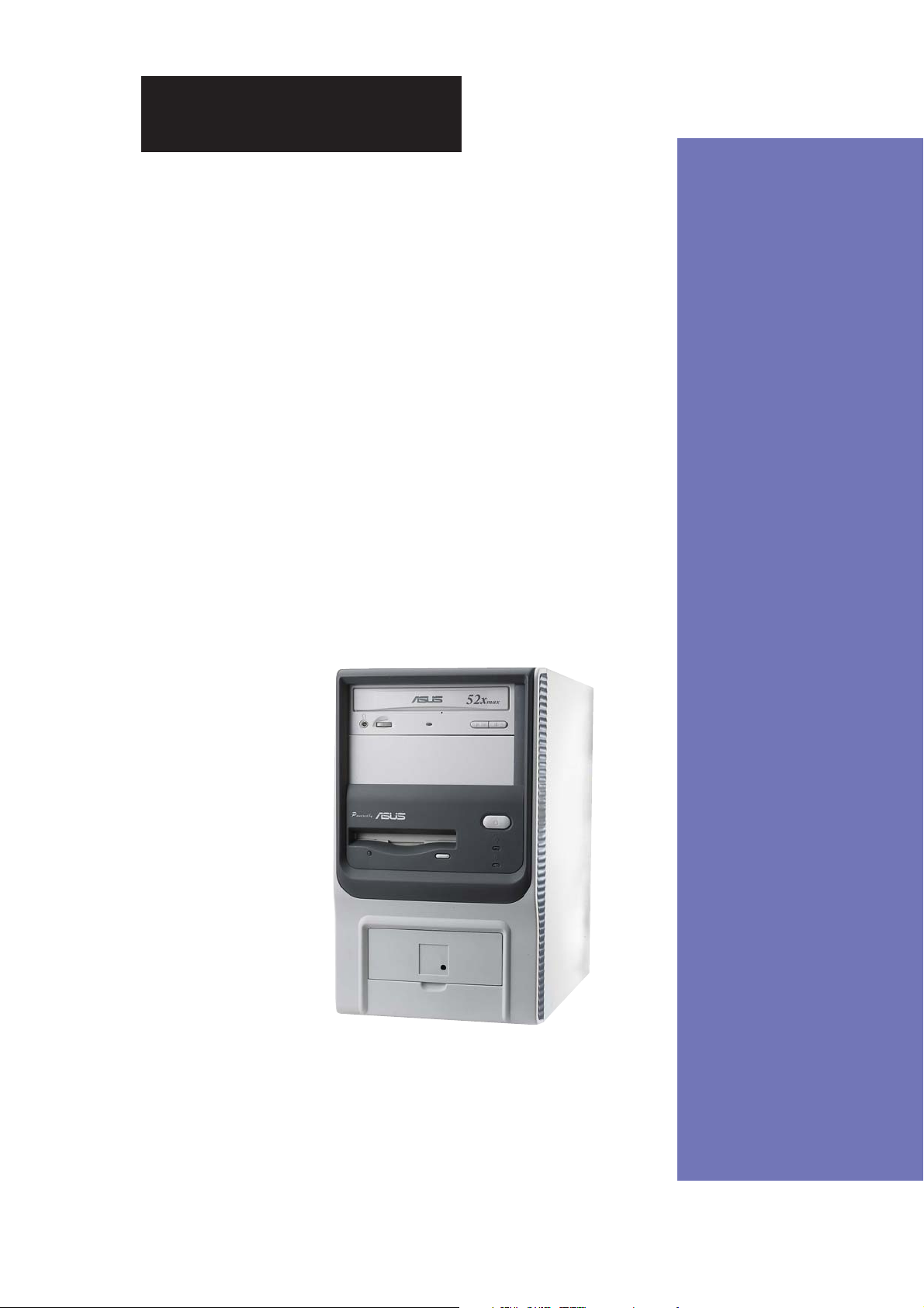
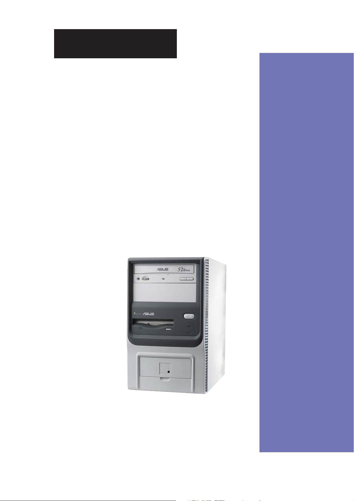
Chapter 1
This chapter gives a general description of
the ASUS Terminator 1 A7VT barebone
system. It includes introduction on the front
and rear panel features, and the internal
features.
ASUS Terminator 1 A7VT barebone system
System Introduction
11
1.1 Welcome!
Thank you for choosing the ASUS Terminator 1!
The ASUS Terminator 1 is an all-in-one barebone system with a versatile
home entertainment feature.
The system comes in a stylish mini-tower casing, and is powered by the
ASUS A7VT motherboard that supports AMD Athlon™ and AMD Duron™
processors.
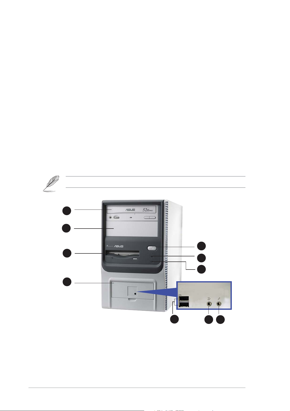
1.2 Front panel
The ASUS Terminator 1 barebone system is composed of the ASUS A7VT
motherboard, a power supply, and a floppy disk drive in the ASUS TriOptix
form factor chassis.
The CD-ROM drive is an optional item.
1
2
3
7
4
5
6
8
9 10
1. Optical drive. This is an optional IDE optical drive.
2. Empty 5.25-inch drive bay. This covered slot is for a second optical drive
or other 5.25-inch storage devices.
3. Floppy drive door. This drive is for a 1.44MB, 3.5-inch floppy disk.
12
Chapter 1: System introduction

4. Power button. Press this button to turn the system on.
5. Power LED. This LED lights up to indicate that the system is ON.
6. HDD LED. This LED lights up when data is being read from or written
to the hard disk drive
7. Front panel I/O door. Flip up this door to show the front panel
input/output ports.
8. USB 2.0 ports. These Universal Serial Bus 2.0 (USB 2.0) ports are
available for connecting USB 2.0 devices such as a mouse, printer,
scanner, camera, PDA, and others.
9. Headphone port. This port connects a headphone with a stereo
mini-plug.
10. Microphone port. This Mic (pink) port connects a microphone.
ASUS Terminator 1 A7VT barebone system
13
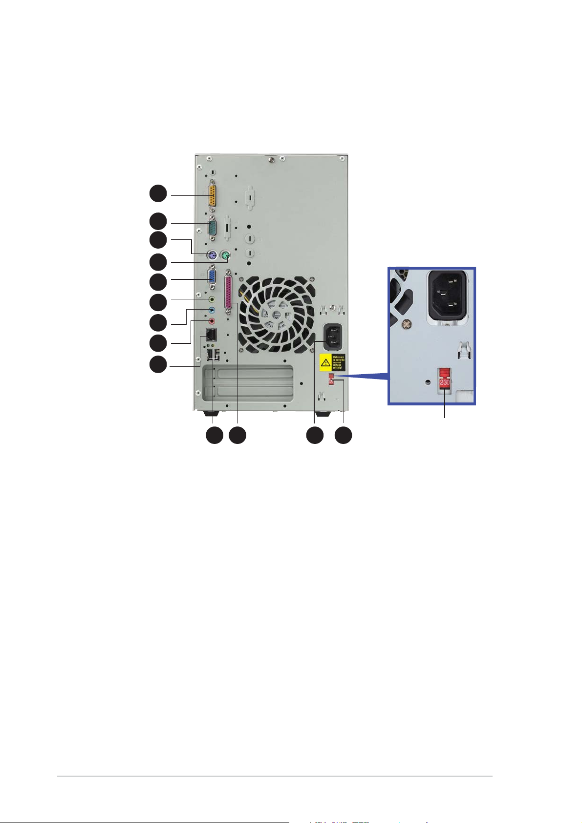
1.3 Rear panel
The system rear panel includes the power socket and several I/O ports
that allow convenient connection of devices.
1
2
3
4
5
6
7
8
9
10 11 12
13
115V/230V
Voltage Selector
1. GAME/MIDI port. This port connects a joystick or game pad for
playing games, and MIDI devices for audio editing.
2. Serial port. This port connects a mouse, modem, or other devices
that conform with serial specification.
3. PS/2 mouse port. This green 6-pin connector is for a PS/2 mouse.
4. PS/2 keyboard port. This purple 6-pin connector is for a PS/2 keyboard.
5. VGA port. This port connects a VGA monitor.
6. Line Out port. This Line Out (lime) port connects a headphone or a
speaker. In 4/6-channel mode, the function of this port becomes Front
Speaker Out.
7. Line In port. This Line In (light blue) port connects a tape player or
other audio sources. In 6-channel mode, the function of this port
becomes Low Frequency Enhanced Output/Center.
14
Chapter 1: System introduction
8. Microphone port. This Microphone (pink) port connects a
microphone. In 4/6-channel mode, the function of this port becomes
Surround Speaker.
The functions of the Line Out (lime), Line In (blue), and Mic (pink) ports
on the rear panel change when you select the 4-channel or 6-channel
audio configuration as shown in the following table.
Audio ports function variation
Port Headphone/2-Channel 4-Channel 6-Channel
Light Blue Line In Line In LFE Output*/Center
Lime Line Out Front Speaker Out Front Speaker Out
Pink Mic In Surround Surround
* LFE Output: Low Frequency Enhanced Output
Windows® 98 SE only supports 4.1-channel speaker setting.
9. LAN (RJ-45) port. This port allows connection to a Local Area
Network (LAN) through a network hub.
10. USB 2.0 ports. These Universal Serial Bus 2.0 (USB 2.0) ports are
available for connecting USB 2.0 devices such as a mouse, printer,
scanner, camera, PDA, and others.
11. Parallel port. This 25-pin port connects a printer, scanner, or other
devices.
12. Power socket. This socket connects the power cable and plug.
13. Voltage selector. This switch allows you to select the appropriate
voltage supply in your area.
Voltage Selector
The switching power supply that came with the system has a voltage
selector switch below the power socket. Use this switch to select the
appropriate voltage according to the voltage supply in your area.
If the voltage supply in your area is 100-127V, set the switch to 115V.
If the voltage supply in your area is 200-240V, set the switch to 230V.
Setting the switch to 115V in a 230V environment will seriously damage
the system!
ASUS Terminator 1 A7VT barebone system
15
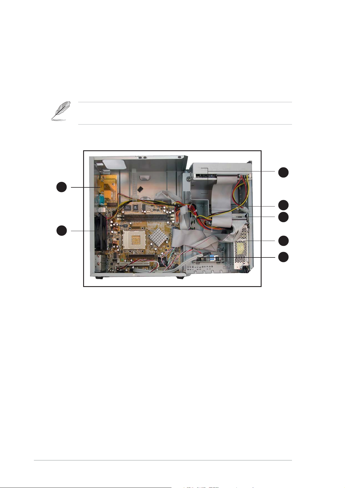
1.4 Internal components
The figure below shows the internal view of the system when you remove
the cover and flip out the drive frame. The standard components already
installed in the system and the locations of the available drive bays are
pointed out.
The system may come with either a PFC (Power Factor Correction) or
non-PFC power supply.
3
1
4
2
1. Game/MIDI/COM1 extension
module
2. Motherboard
3. Two 5.25” drive bays
(Optional CD-ROM)
5
6
7
4. 3.5” HDD drive bay
5. 3.5” floppy drive
6. PFC/Non-PFC power supply
7. USB/audio board
16
Chapter 1: System introduction
Chapter 2
This chapter gives step-by-step instructions
on how to install components into the
barebone system.
ASUS Terminator 1 A7VT barebone system
Basic Installation
17

2.1 Preparation
Before you proceed, make sure that you have all the components that you
plan to install in the system.
Basic components to install
1. Central processing unit (CPU)
2. DDR Dual Inline Memory Module (DIMM)
3. Expansion card(s)
4. Hard disk drive
5. Second optical drive
Tool
Phillips (cross) screw driver
2.2 Before you proceed
Take note of the following precautions before you install components into
the system.
• Use a grounded wrist strap or touch a safely grounded object or
a metal object, such as the power supply case, before handling
components to avoid damaging them due to static electricity.
• Hold components by the edges to avoid touching the ICs on them.
• Whenever you uninstall any component, place it on a grounded
antistatic pad or in the bag that came with the component.
The motherboard comes with an onboard standby power LED. This LED
lights up to indicate that the system is ON, in sleep mode or in soft-off
mode, and not powered OFF. Unplug the power cable from the power
outlet and make sure that the standby power LED is OFF before installing
any system component.
18
Chapter 2: Basic Installation
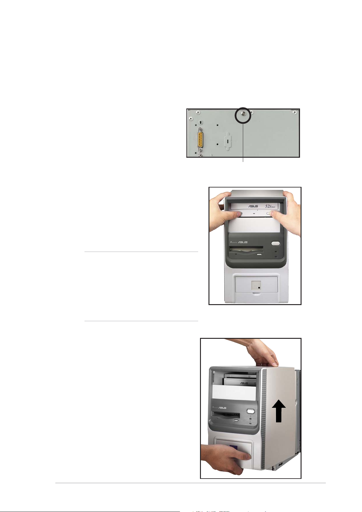
2.3 Removing the cover
The chassis cover is secured by a screw located on the rear panel.
Follow these steps to remove the
chassis cover.
1. Turn the screw
counterclockwise to release
the cover. Set the screw
aside.
Screw
2. Place your hands on both
corners of the front panel, just
beside the CD-ROM frame.
Push on the CD-ROM area
with your thumbs until the
cover tilts forward.
TIP
Another way to release the cover is
to place your hands underneath the
front panel edge, then push the inner
chassis with your thumbs while
pulling the panel with your other
fingers.
3. While supporting the front
panel with one hand, place
your other hand on the top
rear edge of the cover and
carefully lift the cover from the
chassis.
ASUS Terminator 1 A7VT barebone system
19
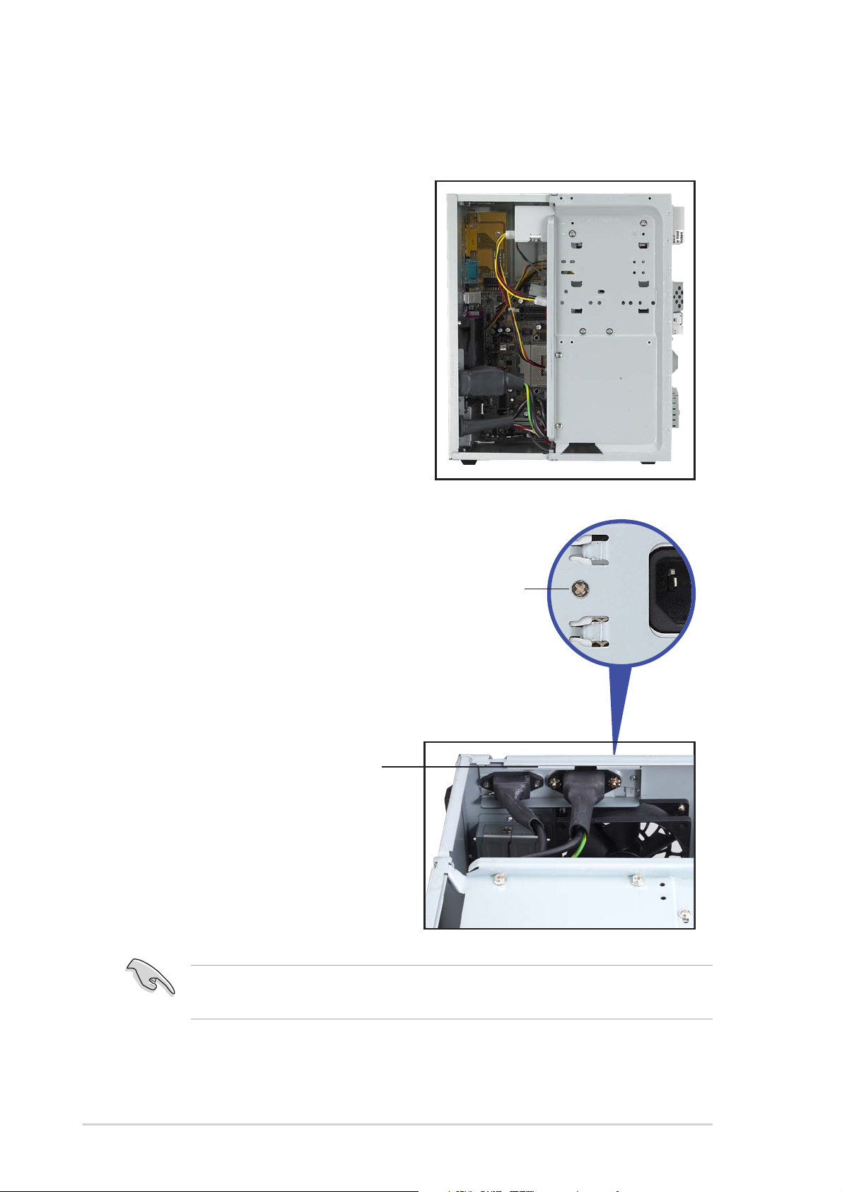
2.4 Detaching the drive frame
Follow these steps to detach the
drive frame.
1. Place the chassis on a flat
surface and turn it on its side.
2. The power socket and voltage
selector switch are attached to
a metal module secured to
the rear panel by a screw.
Remove the screw to release
the power socket module.
Power socket module
Power socket
module screw
20
You must release the power socket module from the rear panel before
detaching the drive frame to avoid breaking the power cable.
Chapter 2: Basic Installation
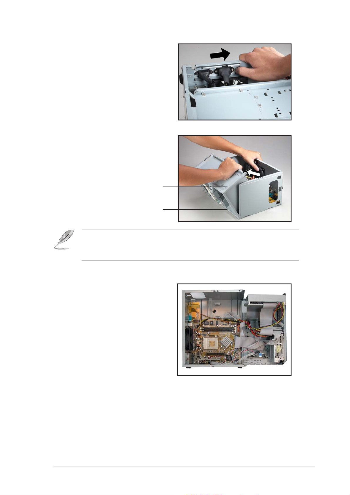
3. Place your thumb on the right
edge of the power socket
module, then slide the module
to the right until it is
completely detached from the
rear panel.
4. Unlatch the drive frame by
pulling it outward.
Drive frame
Swivel edge
The drive frame has a swivel (hinge-like) edge that is attached to the
main chassis. You do not have to completely detach the drive frame from
the chassis when installing components.
5. Carefully lay the drive frame
alongside the main chassis
frame.
ASUS Terminator 1 A7VT barebone system
21
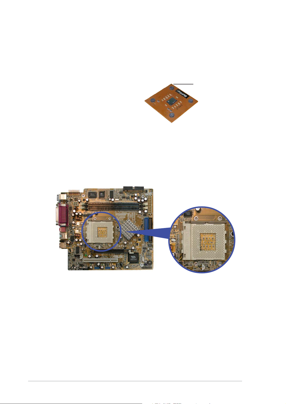
2.5 Installing a CPU
The motherboard comes with a surface mount 462-pin Zero Insertion
Force (ZIF) socket designed for the AMD Athlon™ and AMD Duron™
processors.
Take note of the marked corner
(with gold triangle) on the CPU.
This mark should match a specific
corner on the socket to ensure
correct installation.
Gold triangle
CPU installation
To install the CPU.
1. Locate the 462-pin ZIF socket on the motherboard.
22
Chapter 2: Basic Installation
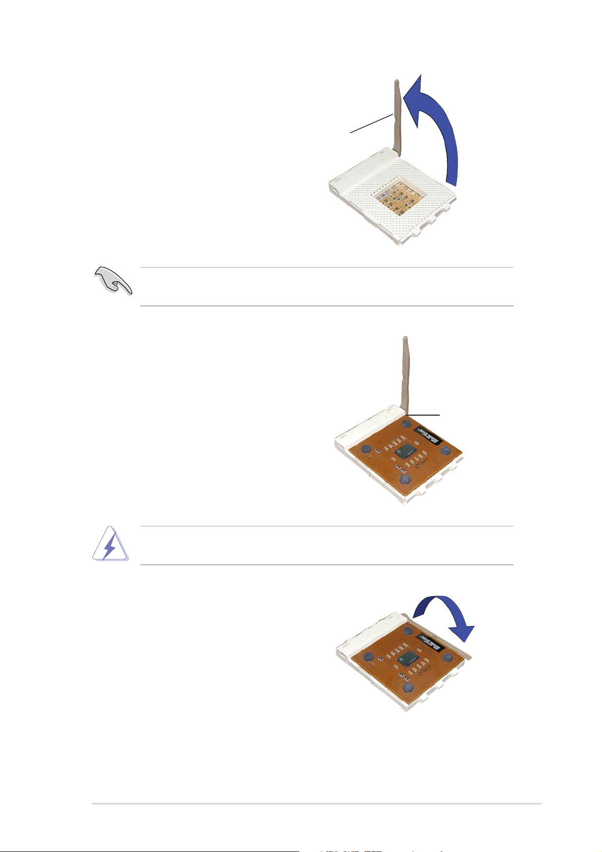
2. Unlock the socket by pressing
the lever sideways, then lift it up
to a 90°-100° angle.
Socket lever
Make sure that the socket lever is lifted up to a 90°-100° angle;
otherwise, the CPU does not fit in completely.
3. Position the CPU above the
socket such that the CPU corner
with the gold triangle matches
the base of the socket lever.
90°-100°
angle
4. Carefully insert the CPU into the
socket until it fits in place.
The CPU fits only in one correct orientation. DO NOT force the CPU into
the socket to prevent bending the pins and damaging the CPU!
5. When the CPU is in place, push
down the socket lever to secure
the CPU. The lever clicks on the
side tab to indicate that it is
locked.
Gold triangle
ASUS Terminator 1 A7VT barebone system
23
2.6 Installing the fan and heatsink assembly
The processor requires a heatsink and fan assembly to ensure optimum
thermal condition and system performance.
Make sure that you properly install the CPU heatsink and fan to avoid
thermal problems.
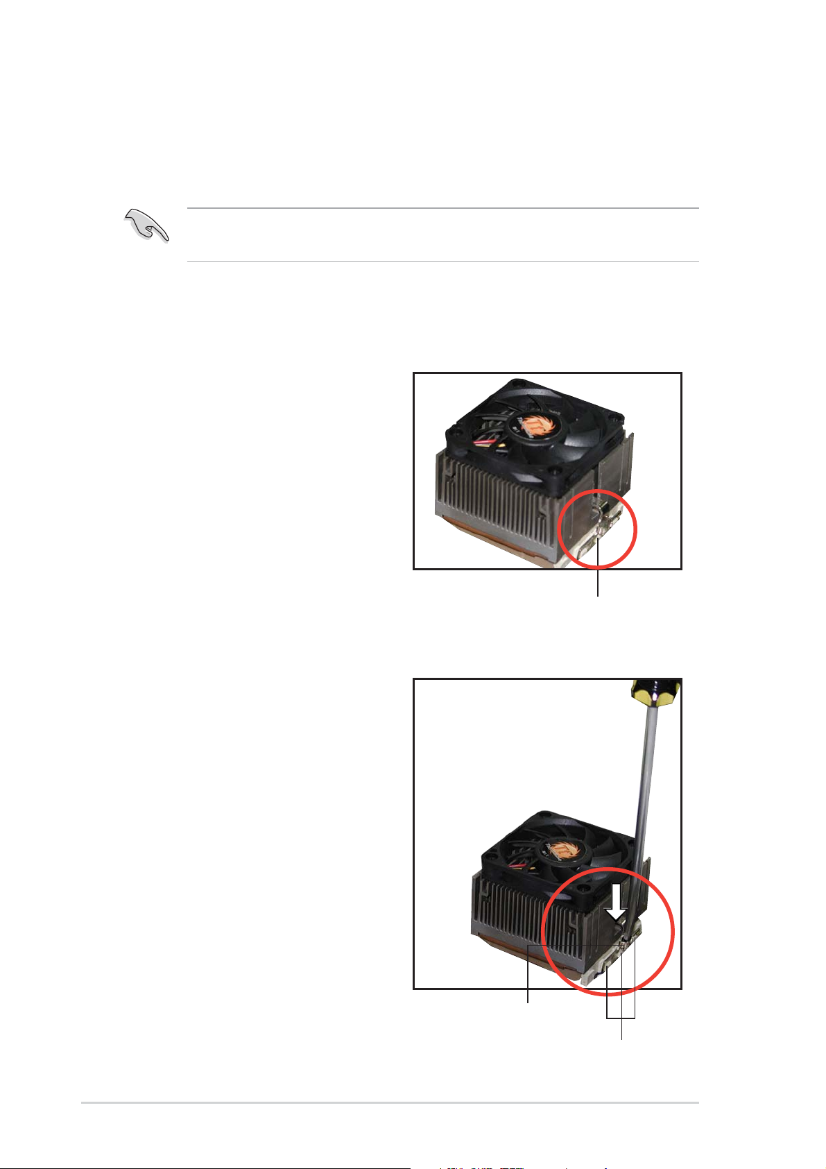
Follow these steps to install the
CPU heatsink and fan.
1. Position the fan and heatsink
assembly on top of the
installed CPU such that the
heatsink fins are perpendicular
to the DDR sockets and PCI
slots.
2. Align one end of the heatsink
bracket to the protruding tabs
on the CPU socket. Hook the
holes of the bracket to the
protruding tabs, making sure
that they fit properly.
3. Using a flat screwdriver,
carefully hook the other end of
the heatsink bracket to the
tabs on the base of the CPU
socket. This secures the fan
and heatsink assembly.
Socket tabs matched to the holes
on the heatsink bracket
24
Heatsink bracket
Socket tabs
Chapter 2: Basic Installation
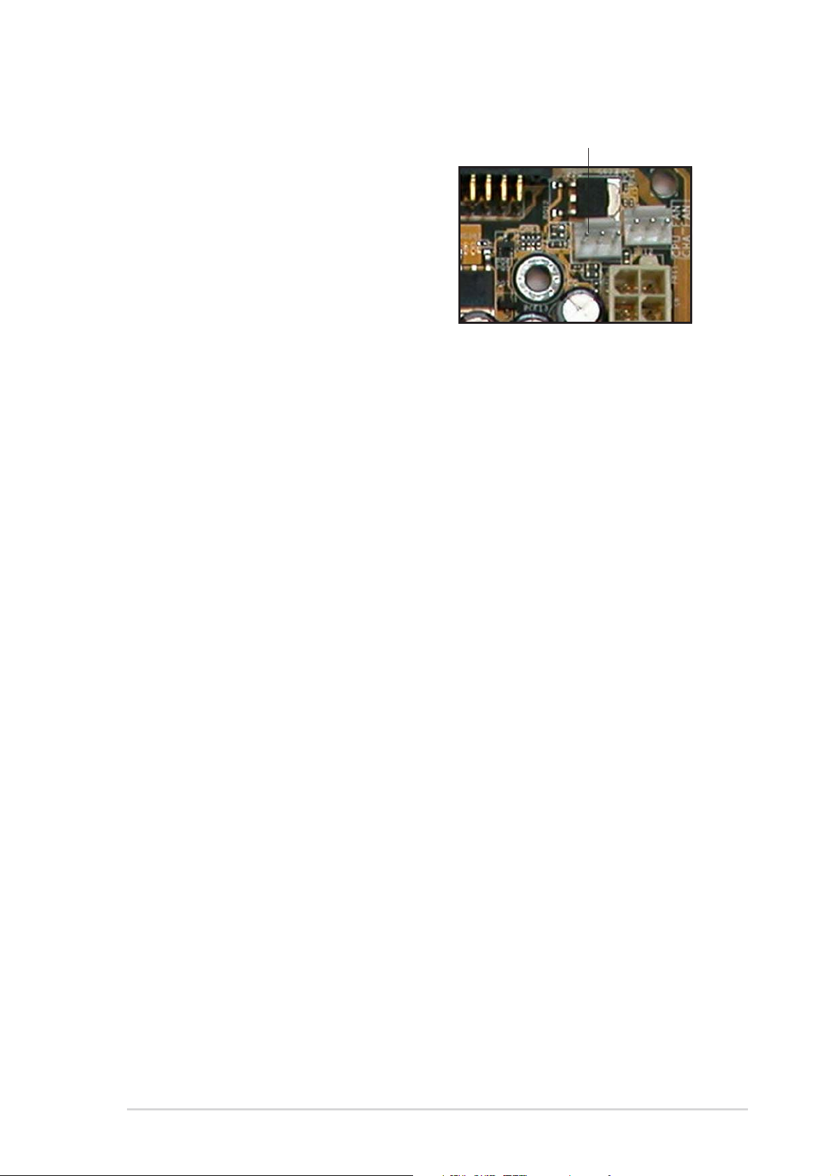
4. Connect the CPU fan cable
from the assembly to the fan
connector labeled CPU_FAN1.
CPU fan connector
(CPU_FAN1)
ASUS Terminator 1 A7VT barebone system
25
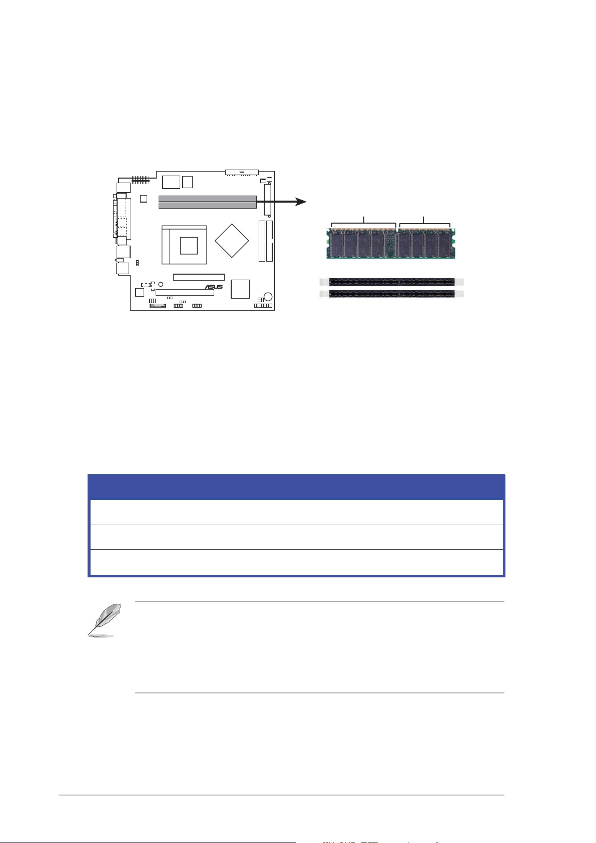
2.7 Installing system memory
The motherboard comes with two Double Data Rate (DDR) Dual Inline
Memory Module (DIMM) sockets. These sockets support up to 2 GB
system memory using unbuffered ECC or non-ECC PC2700/2100 DIMMs.
80 Pins104 Pins
A7VT
®
A7VT 184-Pin DDR DIMM sockets
DIMM2
DIMM1
2.7.1 Memory configurations
You may install any DDR DIMMs with 64 MB, 128 MB, 256 MB, 512 MB,
and 1 GB densities into the DIMM sockets.
Memory frequency/CPU FSB synchronization
CPU FSB DDR DIMM Type Memory Frequency
100 MHz PC2700/PC2100/PC1600 266/266/200 MHz
133MHz PC2700/PC2100/PC1600 333/266/200 MHz
166 MHz PC2700/PC2100/PC1600 333/266/200 MHz
• When using 100 MHz CPU FSB, any DDR DIMM you installed may
run only at a maximum of 266 MHz due to chipset limitation.
• If you are using CPU FSB other than 100 MHz and installed
400 MHz DDR DIMMs, the memory frequency downgrades to
333 MHz.
26
Chapter 2: Basic Installation
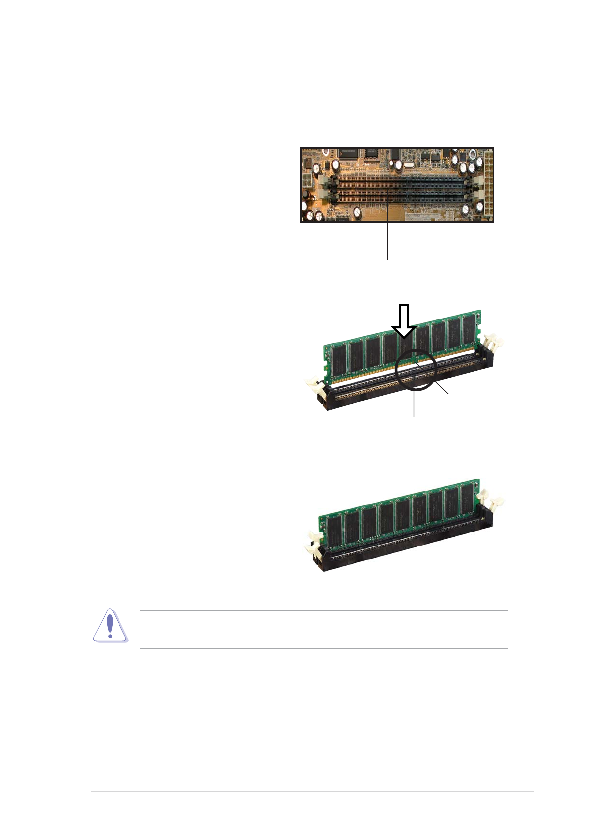
2.7.2 DIMM installation
Follow these steps to install a DDR
DIMM.
1. Locate the two DIMM sockets
on the motherboard.
2. Unlock a socket by pressing
the retaining clips outward.
3. Align a DIMM on the socket
such that the notch on the
DIMM matches the break on
the socket.
DDR DIMM sockets
DIMM notch
4. Firmly insert the DIMM into the
socket until the retaining clips
snap back in place and the
DIMM is properly seated.
A DDR DIMM is keyed with a notch so that it fits in only one direction.
DO NOT force a DIMM into a socket to avoid damaging the DIMM.
Socket break
ASUS Terminator 1 A7VT barebone system
27
2.8 Installing an expansion card
In the future, you may need to install expansion cards. The motherboard
has one 32-bit PCI slot and one Accelerated Graphic Port (AGP) slot. The
following sub-sections describe the slots and the expansion cards that
they support.
2.8.1 Expansion slots
PCI slot
The PCI slot supports PCI slots such as a LAN card, SCSI card, USB
card, and other cards that comply with PCI specifications
AGP slot
The AGP slot supports AGP 4x cards. When you buy an AGP card, make
sure that you ask for one with 1.5V specification.
Install only +1.5V AGP cards. The motherboard does not support 3.3V
AGP cards.
Make sure to unplug the power cord before adding or removing
expansion cards. Failure to do so may cause you physical injury and
damage the motherboard.
28
Chapter 2: Basic Installation
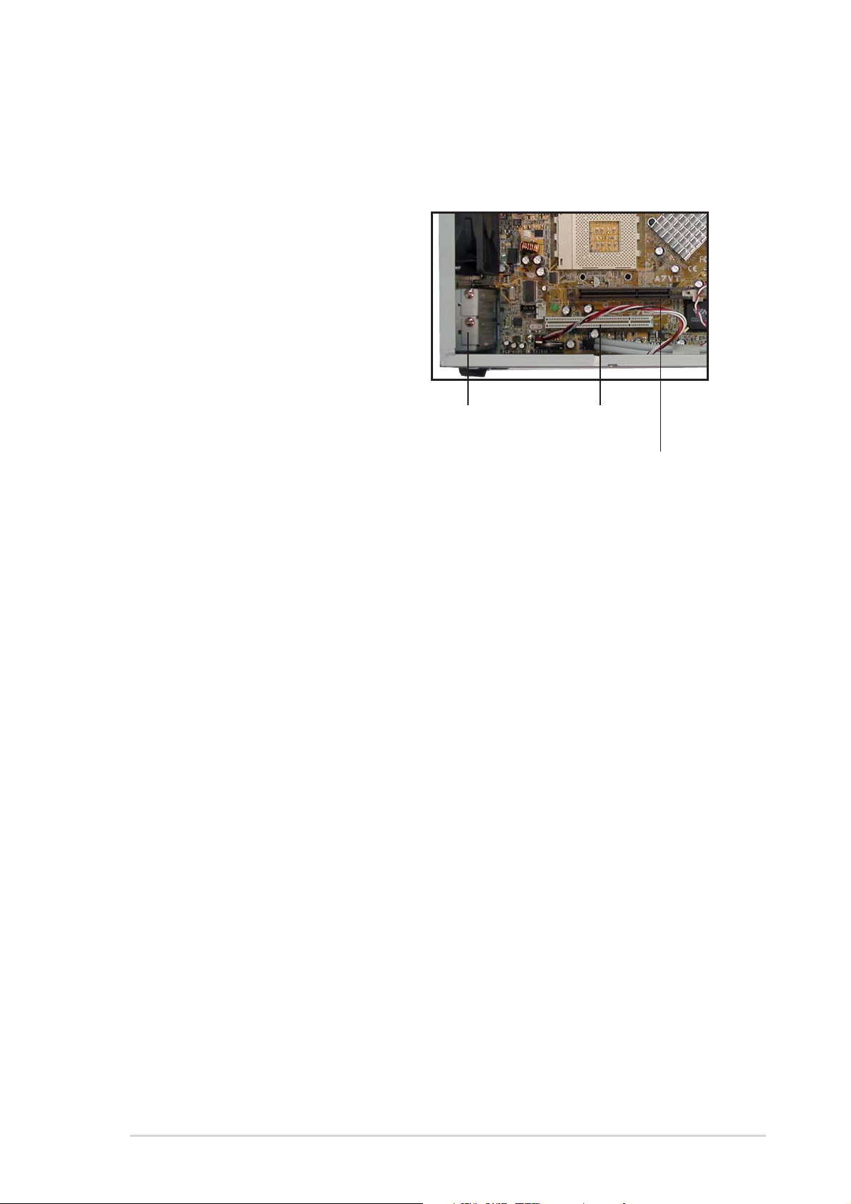
2.8.2 Expansion card installation
Follow these steps to install a PCI
or AGP card.
1. Place the chassis on its side.
2. Remove the metal bracket
opposite the slot that you wish
to use.
3. Align the card golden fingers
to the slot and its metal
bracket to the slot opening on
the chassis.
4. Press the card firmly until it is
properly seated on the slot.
5. Secure the card to the chassis
with a bracket screw.
Metal bracket
PCI slot (PCI1)
AGP slot (AGP1)
2.8.3 Configuring an expansion card
After installing the expansion card, configure it by adjusting the software
settings.
1. Turn on the system and change the necessary BIOS settings, if any.
See Chapter 5 for information on BIOS setup.
2. Install the software drivers for the expansion card.
ASUS Terminator 1 A7VT barebone system
29

2.8.4 Standard interrupt assignments
IRQ Priority Standard Function
0 1 System Timer
1 2 Keyboard Controller
2 N/A Programmable Interrupt
3* 11 USB Universal Host Controller
4* 12 Communications Port (COM1)
5* 13 USB Enhanced Host Controller
6 14 Standard Floppy Disk Controller
7* 15 Printer Port (LPT1)
8 3 System CMOS/Real Time Clock
9* 4 ACPI Mode when used
10* 5 Multimedia Device
11* 6 Network Controller
12* 7 PS/2 Compatible Mouse Port
13 8 Numeric Data Processor
14* 9 Primary IDE Channel
15* 10 Secondary IDE Channel
* These IRQs are usually available for ISA or PCI devices.
2.8.5 IRQ assignments for this motherboard
ABCDEF G H
PCI slot — used — — — — — —
AGP slot used — — — — — — —
USB 1.1 UHCI 1 — — — — shared — — —
USB 1.1 UHCI 1 — — — — — used — —
USB 1.1 UHCI 1 — — — — — — shared —
USB 2.0 EHCI — — — — — — — used
Onboard Audio — — — — — — shared —
Onboard LAN — — — — shared — — —
30
Chapter 2: Basic Installation
 Loading...