

Page 1

DISASSEMBLY PROCEDURE
2
S
SW1 Disassembly
Procedure
Please follow the information provided in this section to perform
the complete disassembly procedure of the notebook. Be sure
to use proper tools described before.
W1 Series Notebook consists of various modules. This chapter describes the
procedures for the complete notebook disassembly. In addition, in between
procedures, the detailed disassembly procedure of individual modules will be
provided for your service needs.
Chapter
The disassembly procedure consists of the following steps:
• Battery Module
• Keyboard Module
• LCD Module
• ODD Module
• HDD Module
• CPU Module
• Memory Module
• Top Cover Module
• Main Board Module
2 - 1
PDF created with pdfFactory Pro trial version www.pdffactory.com
Page 2
DISASSEMBLY PROCEDURE
BATTERY
K/B MODULE
K/B COVER
REMOVAL
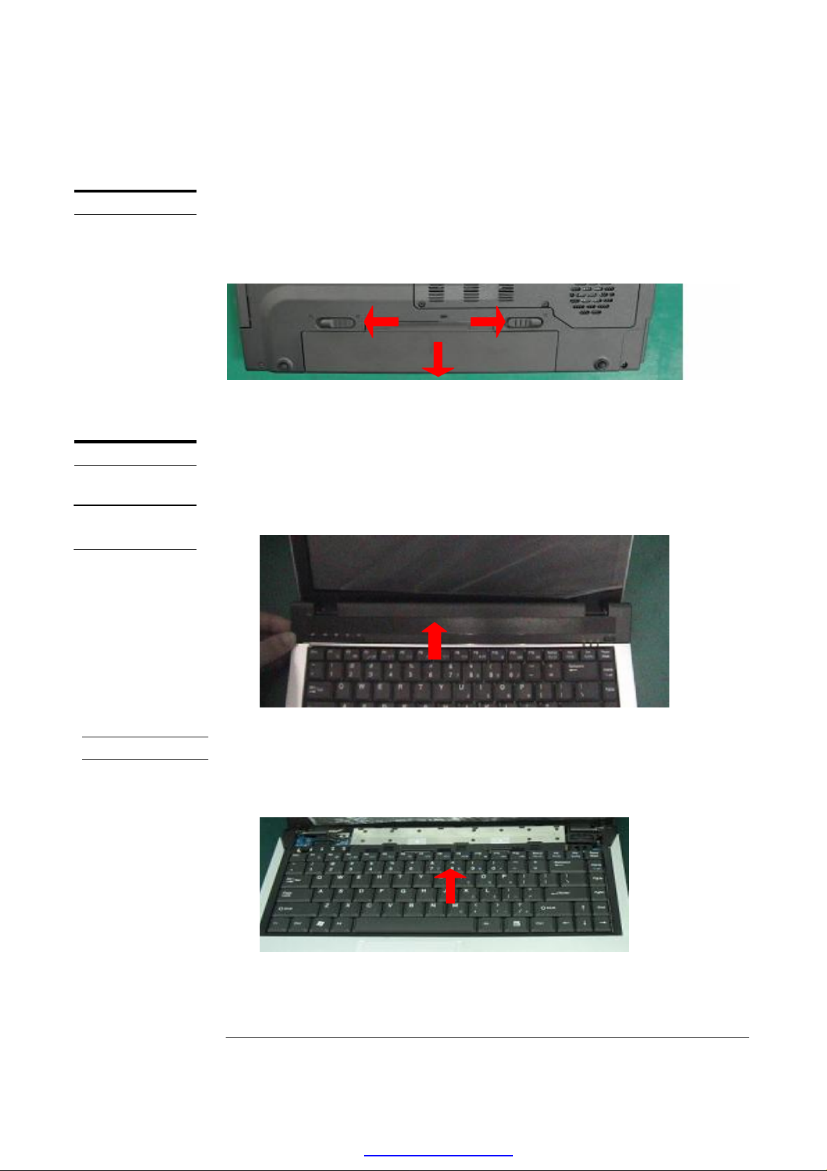
Battery module
The illustration below shows how to remove the Battery Module.
Turn the notebook over, unlock latches and remove the Battery pack from bottom
side of the notebook.
. Keyboard Module
The illustration below shows how to remove the K/B cover and Keyboard Plate.
Removing K/B Cover
1. Unclench K/B Cover at red loop in the chart and drive up it.
K/B REMOVAL
Removing K/B
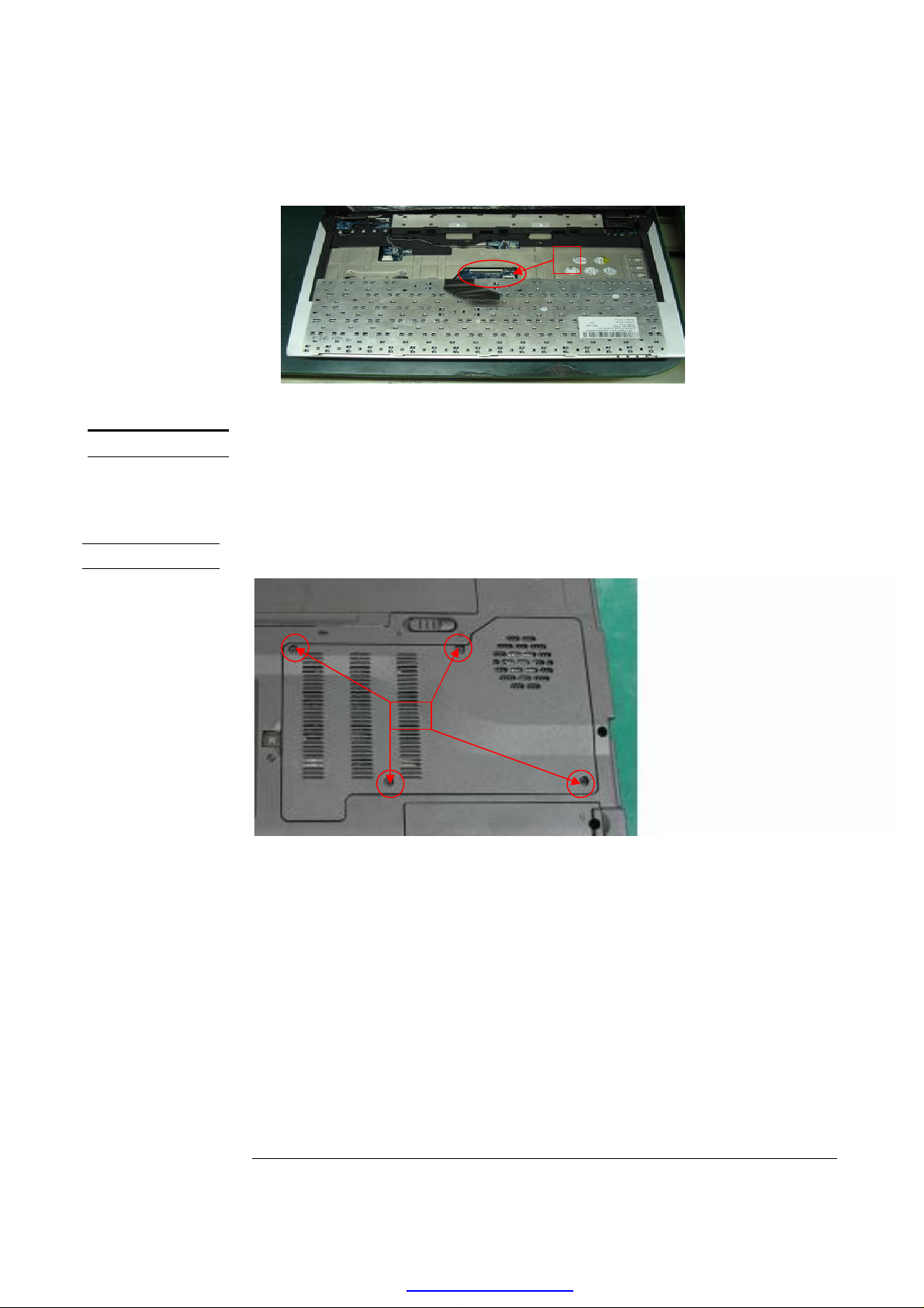
1. Carefully separate Keyboard Plate from Top Cover in the direction of arrow in
the chart.
2. Disconnect K/B Cable from Main Board.
2 - 2
PDF created with pdfFactory Pro trial version www.pdffactory.com
Page 3
DISASSEMBLY PROCEDURE
LCD
LCD REMOVAL
LCD module
The illustrations below show how to remove and disassemble the LCD Module.
The module contains LCD Panel, Inverter Board, LCD Hinge Bracket, Hinge
Cover, LCD Bezel and LCD Cover.
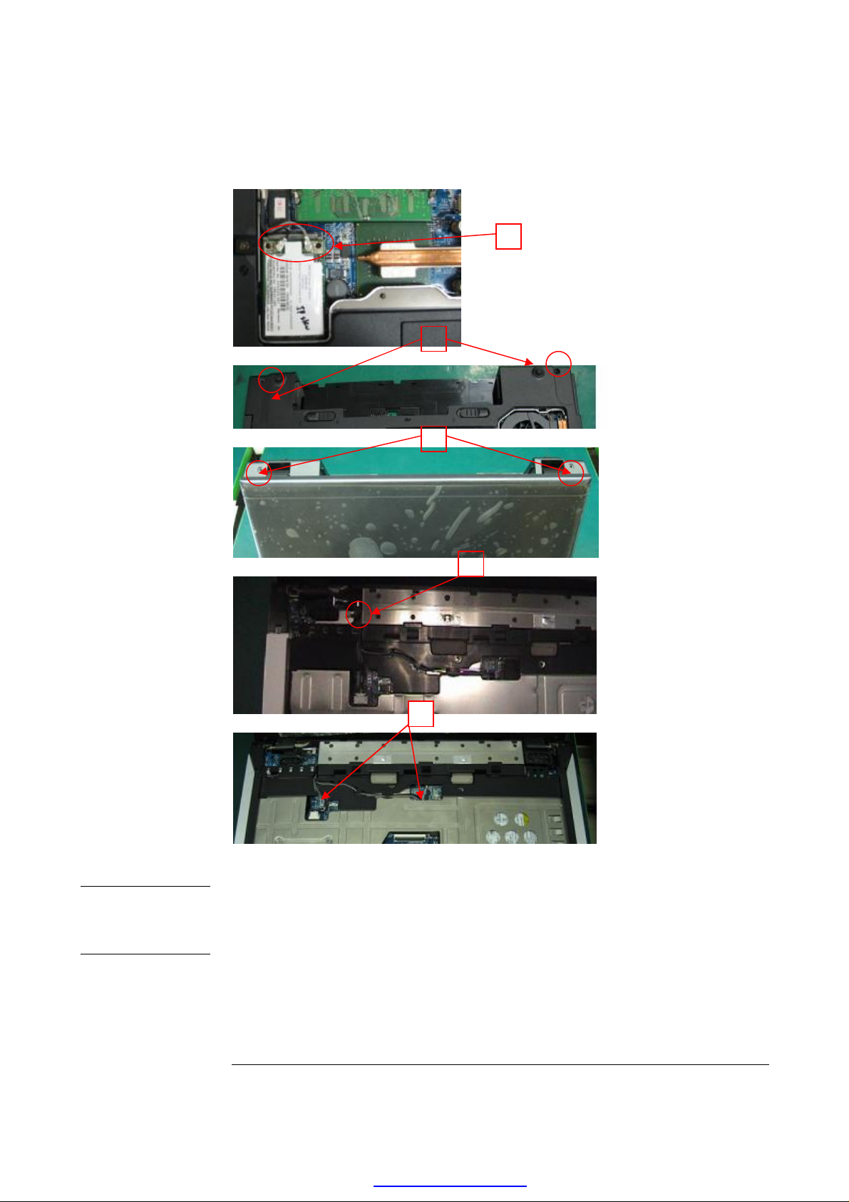
Removing LCD Module
1. Release 4pcs screw on Base Door.
2. Pull out Antenna Conn.
3. Release 2pcs screw on rear Base Cover.
4. Release 2pcs screw on side Base Cover.
5. Release the screw of LCD ground cable.
6. Pull out Antenna Cable, MIC Phone Cable , LCD Cable& LCD Module.
2 - 3
PDF created with pdfFactory Pro trial version www.pdffactory.com
Page 4
DISASSEMBLY PROCEDURE
LCD
DIS-ASSEMBL
Y
Disassembling LCD Module
1. Remove 6pcs rubber pads and release 6pcs screws from the LCD Module
2. Open inside four edges of LCD Bezel with your finger, and then remove
LCD Bezel from LCD Module.
3. Remove Hinge Cover L & R.
4. Release 4pcs screws from LCD Panel and LCD Cover.
5. Disconnect left and right cable on the Inverter board.
2 - 4
PDF created with pdfFactory Pro trial version www.pdffactory.com
Page 5

DISASSEMBLY PROCEDURE
6. Disassemble LCD Panel and release 4pcs screw on the both LCD Bracket.
1,2
3
2 - 5
PDF created with pdfFactory Pro trial version www.pdffactory.com
Page 6

DISASSEMBLY PROCEDURE
ODD MODULE
ODD MODULE
REMOVAL
ODD Module
The illustrations below show how to remove the ODD Module from the notebook.
Removing ODD Module
1. Release 1pcs screw on the rear Base Cover.
2. Pull out the ODD Module from bottom side of notebook.
3. Release 2pcs screw on the ODD Bracket.
2 - 6
PDF created with pdfFactory Pro trial version www.pdffactory.com
Page 7

DISASSEMBLY PROCEDURE
HDD MODULE
HDD MODULE
REMOVAL
HDD Module
The illustrations below show how to remove the HDD Module from the notebook.
Removing HDD Module
1. Release 2pcs screws from bottom of notebook.
2. Pull out the HDD module from notebook.
MEMORY
REMOVAL
MEMORY
REMOVAL
Memory Module
The illustrations below show how to remove the Memory module from the notebook.
The SW1 Series Notebook comes standard without memory onboard.
Removing Memory module
If there is an existing memory, remove it by opening the latches, which will pop
the module up to a 45° angle, and then pulling out the module in that angle.
2 - 7
PDF created with pdfFactory Pro trial version www.pdffactory.com
Page 8

DISASSEMBLY PROCEDURE
CPU
CPU REMOVAL
CPU Module
The illustrations below show how to remove the CPU module from the notebook.
The module contains CPU, CPU Thermal Pad and CPU Thermal Module.
Removing CPU
1. Release 2pcs screw on Fan, pull out Fan Cable and remove Fan Module.
2. Release 4pcs screw with 4,3,2,1 order on the Cooler and pull out Cooler.
2 - 8
PDF created with pdfFactory Pro trial version www.pdffactory.com
Page 9

DISASSEMBLY PROCEDURE
3. To unlock CPU with minus screw driver and follow the direction of arrow below.
4. Carefully pull out CPU upwards with your hand.
TOP COVER
MODULE.
TOP COVER
MODULE
TOP Cover module
The illustrations below show how to disassemble and remove the Top Cover
Module of the notebook. The module contains the Top Cover itself and Touch
Pad Module.
Removing Top Cover Module
1. Release 7pcs screws on the Base.
2. Release 8pcs screw on the Top.
3. Remove the Top Cover from above side of Top Cover.
2 - 9
PDF created with pdfFactory Pro trial version www.pdffactory.com
Page 10

DISASSEMBLY PROCEDURE
M/BMODULE
REMOVAL
Removing Motherboard module
1. Release 7pcs screws on the Main Board.
2. Remove HDD bracket & Modem cable.
3. Pull out DB/B and pull out Speaker R.
4. Pull out M/B Module carefully from right side in the Base Cover to remove
DVI or CRT connector and Modem Connector, and remove 1394 Connector
and Audio Jack to separate the M/B from Base Cover.
5. Pull out Speaker L and remove IO/B cable & Power Jack cable.
2 - 10
PDF created with pdfFactory Pro trial version www.pdffactory.com
Page 11

DISASSEMBLY PROCEDURE
Remove IO
speaker
board and
2 - 11
PDF created with pdfFactory Pro trial version www.pdffactory.com
 Loading...