

Page 1

ROG STRIX
Z490-E
GAMING
用 戶 手 冊
Motherboard
Page 2

ii
Page 3

C16108
第一版
2020 年 3 月發行
版權說明
© ASUSTeK Computer Inc. All rights reserved. 華碩電腦股份有限公司保留所有權利
本用戶手冊包括但不限於其所包含的所有信息皆受到著作權法之保護,未經華碩電
腦股份有限公司(以下簡稱「華碩」)許可,不得任意地仿製、拷貝、摘抄、轉譯或
為其他利用。
免責聲明
本用戶手冊是以「現況」及「以當前明示的條件下」的狀態提供給您。在法律允許
的範圍內,華碩就本用戶手冊,不提供任何明示或默示的擔保及保證,包括但不限於
商業適銷性、特定目的之適用性、未侵害任何他人權利及任何得使用本用戶手冊或無
法使用本用戶手冊的保證,且華碩對因使用本用戶手冊而獲取的結果或通過本用戶手
冊所獲得任何信息之準確性或可靠性不提供擔保。
用戶應自行承擔使用本用戶手冊的所有風險。 用戶明確了解並同意,華碩、華碩
之授權人及其各該主管、董事、員工、代理人或關係企業皆無須為您因本用戶手冊、
或因使用本用戶手冊、或因不可歸責於華碩的原因而無法使用本用戶手冊或其任何部
分而可能生成的衍生、附隨、直接、間接、特別、懲罰或任何其他損失(包括但不限
於利益損失、業務中斷、數據遺失或其他金錢損失)負責,不論華碩是否被告知發生
上開損失之可能性。
由於部分國家或地區可能不允許責任的全部免除或對前述損失的責任限制,所以前
述限制或排除條款可能對您不適用。
用戶知悉華碩有權隨時修改本用戶手冊。本產品規格或驅動程序一經改變,本用戶
手冊將會隨之更新。本用戶手冊更新的詳細說明請您訪問華碩的客戶服務網 ht tp://
support.asus.com,或是直接與華碩信息產品技術支持專線 400-620-6655 聯絡。
於本用戶手冊中提及之第三人產品名稱或內容,其所有權及智能財產權皆為各別產
品或內容所有人所有且受當前智能財產權相關法令及國際條約之保護。
當下列兩種情況發生時,本產品將不再受到華碩之保修及服務:
(1) 本產品曾經過非華碩授權之維修、規格更改、零件替換或其他未經過華碩授權
的行為。
(2)本產品序列號模糊不清或喪失。
本產品的名稱與版本都會印在主板/顯卡上,版本數字的編碼方式是用三個數字組
成,並有一個小數點做間隔,如 1.02G、2.03G 等...數字越大表示版本越新,而越左
邊位數的數字更動表示更動幅度也越大。更新的詳細說明請您到華碩的互聯網瀏覽或
是直接與華碩聯絡。
iii
Page 4

Offer to Provide Source Code of Certain Software
This product may contain copyrighted software that is licensed under the General
Public License (“GPL”) and under the Lesser General Public License Version
(“LGPL”). The GPL and LGPL licensed code in this product is distributed
without any warranty. Copies of these licenses are included in this product.
You may obtain the complete corresponding source code (as defined in the
GPL) for the GPL Software, and/or the complete corresponding source code
of the LGPL Software (with the complete machine-readable “work that uses
the Library”) for a period of three years after our last shipment of the product
including the GPL Software and/or LGPL Software, which will be no earlier than
December 1, 2011, either
(1) for free by downloading it from http://support.asus.com/download;
or
(2) for the cost of reproduction and shipment, which is dependent on the preferred
carrier and the locAMDon where you want to have it shipped to, by sending a
request to:
ASUSTeK Computer Inc.
Legal Compliance Dept.
1F., No. 15, Lide Rd.,
Beitou Dist., Taipei City 112,
Taiwan
In your request please provide the name, model number and version, as stated in
the A oordinate the terms and cost of shipment with you.
The source code will be distributed WITHOUT ANY WARRANTY and licensed
under the same license as the corresponding binary/object code.
This offer is valid to anyone in receipt of this informAMDon.
ASUSTeK is eager to duly provide complete source code as required under various
Free Open Source Software licenses. If however you encounter any problems in
obtaining the full corresponding source code we would be much obliged if you give
us a notificAMDon to the email address gpl@asus.com, stAMDng the product and
describing the problem (please do NOT send large attachments such as source
code archives etc to this email address).
iv
Page 5
三年質保
華碩產品質量保證卡
尊敬的華碩產品用戶:
首先非常感謝您選用華碩公司產品,讓我們有機會向您提供優質的服務。為了使我們的服務讓
您更滿意,在購買後請您認真閱讀此說明並妥善保存此質量保證卡。
保修說明注意事項:
一、 請將此質量保證卡下方的用戶數據填寫完整,並由最終直接經銷商加蓋印章,如果沒有加蓋
印章,請找原購買處補蓋以保障您的權益。請務必保留購買發票或複印件,否則華碩公司將
以產品的出廠日期為參照進行保修。
二、 華碩公司對在中國大陸地區(不包括港澳台地區)發售的、經合法渠道銷售給消費者的華碩
主板及顯卡產品實行三年的免費保修服務。
三、 華碩公司對在中國大陸地區(不包括港澳台地區)發售的、經合法渠道銷售給消費者的華碩
主板及顯卡產品實行全國聯保服務。注:
A. 消費者必須出具正規購買發票或國家認可的有效憑證方可享受全國聯保。
B. 如消費者無法出具正規購買發票,請關注「ASUS 華碩服務」微信公眾中的人工在
請 用 剪 刀 沿 虛 線 剪 下
四、 若經本公司判斷屬下列因素,則不屬於免費保修服務的範圍,本公司將有權利收取維修費
五、 技術支持及維修服務:
用
戶
填
寫
數
據
線咨詢,進行售後保修咨詢。
用:
A. 超過華碩提供的質保有效期的主板、顯卡產品。
B. 因遇不可抗拒外力(如:水災、火災、地震、雷擊、颱風等)或人為之操作使用不
慎造成之損害。
C. 未按產品說明書條例的要求使用、維護、保管而造成的損壞。
D. 用戶擅自或請第三方人員自行檢修、改裝、更改組件、修改線路等。
E. 因用戶自行安裝軟件即設置不當所造成之使用問題及故障。
F. 本公司產品序列號標貼撕毀或無法辨認,塗改保修服務卡或與實際產品不符。
G. 其他不正常使用所造成之問題及故障。
1. 我們建議您先登錄華碩官方會員網站(http://vip.asus.com),對您購買的華碩產品
進行在線註冊,註冊後您將會定期得到我們發送的產品信息以及技術數據;
2. 如果您在使用華碩產品的過程中遇到問題,您可以首先查閱用戶手冊,尋找答案;
3. 您亦可訪問華碩中文網站技術支持頁面(http://www.asus.com.cn/support)查詢到
相應的技術支持信息與常見問題排除;
4. 登錄我們的在線技術支持服務區進行咨詢(http://vip.asus.com.cn/VIP2/Services/
QuestionForm/TechQuery);
5. 也歡迎您撥打華碩 7x24 小時(國家法定節假日除外)技術支持專線 400-620-
6655,由我們的在線工程師為您提供服務;(註:未開通 400 的地區或使用移動
電話,請撥打技術支持電話 020-28047506)
6. 如果您使用的華碩產品由於硬件故障,需要維修服務,您可以直接聯繫您的經銷
商,通過經銷商及遍佈全國的華碩展示服務中心進行後續相應的檢修服務。
7. 無論通過何種方式來尋求技術服務,請您務必要明確告知您使用的產品型號、BIOS
版本、搭配之硬件、詳細的故障現象等,以利於華碩工程師能幫助您更加準確快速
地判斷出故障的原因。
用戶名稱 購買日期
聯繫人 聯繫電話
聯繫地址
經銷商名稱 產品種類
產品型號 產品序列號
全國聯保
v
Page 6

vi
Page 7

目錄
華碩產品質量保證卡 .................................................................................................................. v
安全性須知 ................................................................................................................................... ix
關於這本用戶手冊 ....................................................................................................................... x
ROG STRIX Z490-E GAMING 規格列表 ....................................................................... xiii
具有共享帶寬的連接端口 .....................................................................................................xvii
產品包裝 ....................................................................................................................................xviii
建立 PC 系統所需的其他工具與元件 ...............................................................................xix
第一章:產品介紹
1.1 主板安裝前 .................................................................................................................... 1-1
1.2 主板結構圖 .................................................................................................................... 1-2
第二章:硬件設備信息
2.1 創建您的電腦系統 ...................................................................................................... 2-1
2.1.1 安裝中央處理器 .......................................................................................... 2-1
2.1.2 安裝冷卻系統 ............................................................................................... 2-3
2.1.3 安裝內存條 .................................................................................................... 2-5
2.1.4 安裝 M.2 ........................................................................................................ 2-6
2.1.5 安裝附加冷卻套件 ......................................................................................2-9
2.1.6 安裝主板 ......................................................................................................2-10
2.1.7 安裝 ATX 電源 .........................................................................................2-11
2.1.8 安裝 SATA 設備 .......................................................................................2-12
2.1.9 安裝前面板輸出/輸入連接端口...........................................................2-13
2.1.10 安裝擴展卡 ..................................................................................................2-14
2.1.11 安裝 Wi-Fi 天線 .........................................................................................2-16
2.2 BIOS 更新應用程序 ..................................................................................................2-17
2.3 主板後側與音頻連接端口 ......................................................................................2-18
2.3.1 後側面板連接端口 ....................................................................................2-18
2.3.2 音頻輸出/輸入連接圖標說明 ...............................................................2-19
2.4 第一次啟動電腦 .........................................................................................................2-22
2.5 關閉電源 .......................................................................................................................2-22
vii
Page 8

目錄
第三章:BIOS 程序設定與 RAID 支持
3.1 認識 BIOS 程序............................................................................................................ 3-1
3.2 BIOS 設定程序 ............................................................................................................. 3-2
3.3 EZ Update ..................................................................................................................... 3-2
3.4 華碩 EZ Flash 3 .......................................................................................................... 3-3
3.5 華碩 CrashFree BIOS 3............................................................................................ 3-4
3.6 RAID 功能設定 ............................................................................................................ 3-5
附錄
Q-Code 列表 ............................................................................................................................A-1
華碩的聯絡信息 ......................................................................................................................A-5
viii
Page 9

安全性須知
電氣方面的安全性
• 為避免可能的電擊造成嚴重損害,在搬動電腦主機之前,請先將電腦電源線暫時
從電源插槽中拔掉。
• 當您要加入硬件設備到系統中時,請務必先連接該設備的數據線,然後再連接電
源線。可能的話,在安裝硬件設備之前先拔掉電腦的電源電源線。
• 當您要從主板連接或拔除任何的數據線之前,請確定所有的電源線已事先拔掉。
• 在使用擴展卡或擴展卡之前,我們建議您可以先尋求專業人士的協助。這些設備
有可能會干擾接地的迴路。
• 請確定電源的電壓設置已調整到本國/本區域所使用的電壓標準值。若您不確定您
所屬區域的供應電壓值為何,請就近詢問當地的電力公司人員。
• 如果電源已損壞,請不要嘗試自行修復。請將之交給專業技術服務人員或經銷商
來處理。
操作方面的安全性
• 在您安裝主板以及加入硬件設備之前,請務必詳加閱讀本手冊所提供的相關信
息。
• 在使用產品之前,請確定所有的排線、電源線都已正確地連接好。若您發現有任
何重大的瑕疵,請儘速聯絡您的經銷商。
• 為避免發生電氣短路情形,請務必將所有沒用到的螺絲、回形針及其他零件收
好,不要遺留在主板上或電腦主機中。
• 灰塵、濕氣以及劇烈的溫度變化都會影響主板的使用壽命,因此請盡量避免放置
在這些地方。
• 請勿將電腦主機放置在容易搖晃的地方。
• 若在本產品的使用上有任何的技術性問題,請和經過檢定或有經驗的技術人員聯
絡。
• 主板應該在溫度為 0℃ 至 40℃ 的環境中使用。
REACH
謹遵守 REACH(Registration, Authorisation, and Restriction of Chemicals)管理
規範,我們會將產品中的化學物質公告在華碩 REACH 網站,詳細請參考 http://csr.
asus.com/english/REACH.htm。
請勿將本主板當作一般垃圾丟棄。本產品零組件設計為可回收利用。這
個打叉的垃圾桶標誌表示本產品(電器與電子設備)不應視為一般垃圾
丟棄,請依照您所在地區有關廢棄電子產品的處理方式處理。
ix
Page 10

關於這本用戶手冊
產品用戶手冊包含了所有當您在安裝華碩主板時所需用到的信息。
用戶手冊的編排方式
用戶手冊是由下面幾個章節所組成:
• 第一章:產品介紹
您可以在本章節中發現諸多華碩所賦予本主板的優異特色。利用簡潔易懂的說
明讓您能很快地掌握本主板的各項特性,當然,在本章節中我們也會提及所有能
夠應用在本主板的新產品技術。
• 第二章:硬件設備信息
本章節描述所有您在安裝系統元件時必須完成的硬件安裝程序。詳細內容有:
處理器與內存安裝、跳線選擇區設置以及主板的各種設備接口。
• 第三章:BIOS 程序設置與 RAID 支持
本章節描述如何使用 B IOS 設置程序、通過 E Z Fl ash Uti li ty 更新 BIO S 與
RAID 支持。
x
Page 11

提示符號
為了能夠確保您正確地完成主板設置,請務必注意下面這些會在本手冊中出現的標
示符號所代表的特殊含意。
小心: 提醒您在進行某一項工作時要注意勿傷害到電腦主板元件與注意您
自身的安全。
重要: 此符號表示您必須要遵照手冊所描述之方式完成一項或多項軟硬件
的安裝或設置。
注意:提供有助於完成某項工作的訣竅和其他額外的信息。
哪裡可以找到更多的產品信息
您可以通過下面所提供的兩個渠道來獲得您所使用的華碩產品信息以及軟硬件的升
級信息等。
1. 華碩網站
您可以到 http://www.asus.com.cn 華碩電腦互聯網站取得所有關於華碩軟硬件產
品的各項信息。
2. 其他文件
在您的產品包裝盒中除了本手冊所列舉的標準配件之外,也有可能會夾帶有其他的
文件,譬如經銷商所附的產品保證單據等。
xi
Page 12
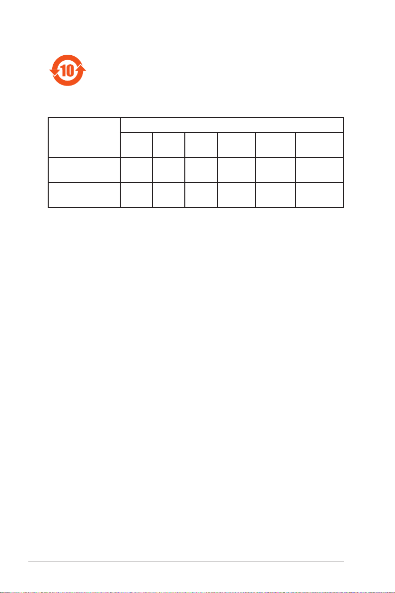
電子電氣產品有害物質限制使用標識要求:圖中之數字為產品之環保
使用期限。只指電子電氣產品中含有的有害物質不致發生外洩或突變
從而對環境造成污染或對人身、財產造成嚴重損害的期限。
有害物質的名稱及含量說明標示:
有害物質
部件名稱
印刷電路板及其電
子組件
外部信號連接口及
線材
本表格根據 SJ/T 11364 的規定編制。
○: 表示該有害物質在該部件所有均質材料中的含量均在 GB/T 26572 規定的限量
要求以下。
×: 表示該有害物質至少在該部件的某一均質材料中的含量超出 GB/T 26572 規定
的限量要求,然該部件仍符合歐盟命令 2011/65/EU 的規范。
備註:此產品所標示的環保使用期限,系指在一般正常使用狀況下。
鉛(Pb) 汞(Hg) 鎘(Cd)
× ○ ○ ○ ○ ○
× ○ ○ ○ ○ ○
六價鉻
(Cr(VI))
多溴聯苯
(PBB)
多溴二苯醚
(PBDE)
xii
Page 13

ROG STRIX Z490-E GAMING 規格列表
中央處理器 支持採用 LGA 1200 規格插槽的第 10 代 Intel® Core™、
Pentium® Gold 與 Celeron® 處理器*
支持 14nm 處理器
支持 Intel® Turbo Boost 2.0 技術與 Intel® Turbo Boost Max
3.0 技術**
* 請訪問華碩網站 www.asus.com.cn 取得最新的 Intel® 處理器支持列表。
** Intel® Turbo Boost Max 3.0 技術支持依照處理器的類型而不同。
芯片組 Intel® Z490 芯片組
內存 4 x
內 存 插 槽,支 持 最 高 128 G B DDR4 4600(超頻)/ 4500
(超頻)/ 4400(超頻)/
4000
(超頻)
頻)
/ 3466
(超頻)
2800
/ 3866
(超頻)
/ 3200
(超頻)
/ 2666 / 2400 / 2133
(超頻)
/ 3400
(超頻)
4266
/ 3733
(超頻)
/ 3000
(超頻)
/ 4133
(超頻)
/ 3333
(超頻)
(超頻)
/ 2933
MHz Non-ECC Un-
(超頻)
/ 3600
/ 3300
(超頻)
(超
buffered 內存條*
支持雙通道內存架構
支持 Intel® Extreme Memory Profile(XMP)技術
OptiMem II
* 第 10 代 Intel® C or e™ i9/i7 處理器支持原 生
2933/2800/2666/2400/2133,詳細信息請參考最新的內存合格
供應商支持列表(QVL)。
顯卡 1 x DisplayPort 1.4*
1 x HDMI™ 1.4b
* DisplayPort 1.4 支持最高分辨率可達 4096 x 2304 @60Hz。請
至www.intel.com 以了解最新更新信息。
** 顯卡規格依照處理器的類型而不同。
擴展槽
Intel® 第 10 代處理器*
2 x PCIe 3.0 x16 擴展卡擴展插槽(支持 x16 或 x8/x8 模
式)
Intel® Z490 芯片組
1 x PCIe 3.0 x16 擴展卡擴展插槽(支持 x4 模式)
3 x PCIe 3.0 x1
* 支持來自 CPU 的 PCIe 通道分支,以運行 RAID on CPU 功能。
擴展卡擴展插槽
多重圖形顯示控制器 支持 NVIDIA 2-Way SLI® 技術
支持 AMD 3-Way CrossFireX™ 技術
存儲設備連接槽
共支持 2 x M.2 插槽與 6 x SATA 6Gb/s 連接端口
Intel® Z490 芯片組
M.2_1 插槽(Ke y M),支持 2242/2260/2280/22110
類型存儲設備(支持 PCIe 3.0 x4 與 SATA 模式)*
M.2_2 插槽(K ey M),支持 2242/2260/2280/22110
類型存儲設備(支持 PCIe 3.0 x4 模式)**
6 x SATA 6Gb/s 連接端口**
Intel® Rapid Storage Technology 技術,支持 Raid 0、1、5、10
Intel® Optane™ 內存
* 當 M.2_1 以 SATA 模式運行時,SATA6G_2 將會關閉。
** M.2_2 與 SA TA6G_56 插槽共享帶寬。當 M.2_2 運行時,
SATA_56 將會關閉。
網絡功能 1 x Intel® I225-V 網絡控制器
華碩 LANGuard 以太網端口
/
/
(下頁繼續)
xiii
Page 14

ROG STRIX Z490-E GAMING 規格列表
無線網絡與藍牙 2x2 W i-Fi 6(802.11a/b/g/n/a c/ax)支持 1024Q A M/
USB
音頻 ROG SupremeFX 8 聲道高保真音頻編碼器 CODEC
後側面板設備連接端口
OFDMA/MU-MIMO
支持最高 2.4Gbps 數據傳輸速率
支持雙帶寬 2.4/5GHz
支持通道帶寬:HT20/HT40/HT80/HT160
支持 CNVI 界面
藍牙 v5.1*
* 藍牙
v5.1 功能僅支持 Windows 19041 或更高的版本。
後側面板 USB 連接端口(共 10 端口)
連接端口
連接端口
連接端口(
連接端口(
網絡控制器
連接端口
(3 x T yp e-A + 1 x USB
(4 x Type-A)
連接端口(
3 x T ype-A + 1 x U SB
2 x Type-A
4 x Type-A
)
)
4 x USB 3.2 Gen 2
Type-C®)
2 x USB 3.2 Gen 1
4 x USB 2.0
前側面板 USB 連接端口(共 7 端口)
1 x US B 3.2 Gen 2 前側面板連接端口(支持 USB
Type-C®)
1 x USB 3.2 Gen 1 連接端口可擴展 2 組 USB 3.2 Gen 1
連接端口
2 x USB 2.0 連接端口可擴展 4 組 USB 2.0 連接端口
S1220A
- 自動檢測前後耳機孔阻抗
- 音頻界面檢測、多音源獨立輸出(Multi-Strea ming)技術
與前端面板音頻插孔功能
- 支持 120 dB SNR 立體聲輸出與 113 dB SNR 錄音輸入
- 最高支持 32-Bit/192kHz 回放*
音頻功能:
- 雙耳機擴大器
- SupremeFX Shielding 技術
- 鍍金音頻接口
- 後側面板具備有光纖 S/PDIF 數位輸出連接端口
- 日本製音頻電容器
- 音頻蓋
* 由於 HDA 帶寬的限制,8 聲道音頻不支持 32-bit/192kHz。
4 x USB 3.2 G en 2
2 x USB 3.2 Gen 1
4 x USB 2.0
1 x DisplayPort 連接端口
1 x HDMI™ 連接端口
1 x 華碩 Wi-Fi 模塊
1 x Intel® I225-V
5 x
1 x 光纖 S/PDIF 輸出端口
1 x BIOS FlashBack™ 按鈕
®
Type-C
)
鍍金音頻接口
xiv
(下頁繼續)
Page 15

ROG STRIX Z490-E GAMING 規格列表
內置 I/O 設備連接端口 風扇與冷卻相關
特殊功能
1 x 4-Pin CPU 風扇接口
1 x 4-Pin CPU OPT 風扇接口
1 x 4-Pin AIO Pump
2 x 4-Pin 機箱風扇接口
1 x 4-Pin M.2 風扇接口
1 x W_PUMP+
1 x VRM 散熱片風扇接口
電源相關
1 x 24-pin 主電源插座
1 x 8-pin +12V 電源插座
1 x 4-pin +12V 電源插座
保存相關
2 x M.2 插槽(Key M)
6 x SATA 6Gb/s 連接端口
USB
1 x U SB 3.2 Ge n 2 前側面板連接端口(支持 US B
Type-C®)
1 x USB 3.2 Gen 1 連接端口可擴展 2 組 USB 3.2 Gen 1 連
接端口
2 x USB 2.0 連接端口可擴展 4 組 USB 2.0 連接端口
其他類
2 x AURA 可定址 Gen 2 接口
2 x AURA RGB 接口
1 x Clear CMOS 接口
1 x CPU 超壓接針
1 x 前面板音源插座(AAFP)
1 x 20-3 Pin 機箱警示功能的系統面板插座
1 x 熱感應接口
1 x Thunderbolt 接口
華碩 Q-Design
- 華碩 Q-Code
- 華碩 Q-DIMM
-
華碩 Q-LED
啟動設備指示燈 [黃綠色])
- 華碩 Q-Slot
華碩散熱解決方案
-
M.2 散熱蓋
鋁製
華碩 EZ DIY
-
BIOS FlashBack™ 按鈕
-
BIOS FlashBack™ LED 指示燈
-
Procool II
-
預裝 I/O 支架
-
安全插槽
Aura Sync
- 標準 RGB 接口
- 可定址 Gen 2 RGB 接口
接口
接口
(處理器 [紅色]、內存 [黃色]、顯卡 [白色]、
(下頁繼續)
xv
Page 16

ROG STRIX Z490-E GAMING 規格列表
軟件功能 ROG 獨家軟件
BIOS 功能 192 (128+64) Mb Flash ROM、UEFI AMI BIOS
管理功能 WOL by PME、PXE
支持操作系統 Windows® 10 - 64 位
主板尺寸 ATX 型式
- RAMCache III
- ROG CPU-Z
- GameFirst VI
- Sonic Studio III + Sonic Studio Virtual Mixer
- Sonic Radar III
- DTS® Sound Unbound
- Overwolf
- 防毒軟件
華碩獨家軟件
Armoury Crate
- Aura Creator
- Aura Sync
AI Suite 3:
- 五向全方位優化調校
TPU
EPU
DIGI+ VRM
Fan Xpert 4
Turbo app
- EZ update
UEFI BIOS
AI Overclocking
華碩 EZ DIY
- 華碩 CrashFree BIOS 3
- 華碩 EZ Flash 3
- 華碩 UEFI BIOS EZ 模式
FlexKey
12 x 9.6 英寸(30.5 x 24.4 厘米)
xvi
規格若有任何更改,恕不另行通知。請至華碩官網查詢最新規格。
Page 17
具有共享帶寬的連接端口
A
C
A
C
B
B
說明 1 2
PCIEX16_1 x16 x8
A
PCIEX16_2 - x8
說明
M.2_2 x4 x2
B
SATA_56 - V
說明 1 2
M.2_1 SATA 模式 PCIe 模式
C
SATA_2 關閉 開啟
1 2
• 當 M.2_1 以 SATA 模式運行時,SATA6G_2 將會關閉。
• M.2_2 與 S A TA6G_56 插槽共享帶寬。當 M.2_2 運行時,
SATA_56 將會關閉。
xvii
Page 18

產品包裝
請檢查下面所列出的各項標準配件是否齊全。
主板 1 x ROG STRIX Z490-E GAMING 主板
排線 1 x 可定址 RGB 燈條延長排線
1 x RGB 燈條延長排線
4 x SATA 6Gb/s 排線
1 x 熱敏電阻排線包
ROG 附加冷卻套件 1 x ROG 輔助風扇 (40mm)
1 x 冷卻套件螺絲包
其他類 1 x 束線包
2 x M.2 橡膠軟墊
2 x M.2 SSD 螺絲包
1 x ROG Strix 貼紙
1 x ROG Strix 感謝卡
1 x 華碩 2x2 雙頻 Wi-Fi 行動天線
應用程序光盤 1 x 應用程序光盤
相關文件 1 x 用戶手冊
若以上列出的任何一項配件有損壞或是短缺的情形,請儘速與您的經銷
商聯絡。
xviii
Page 19
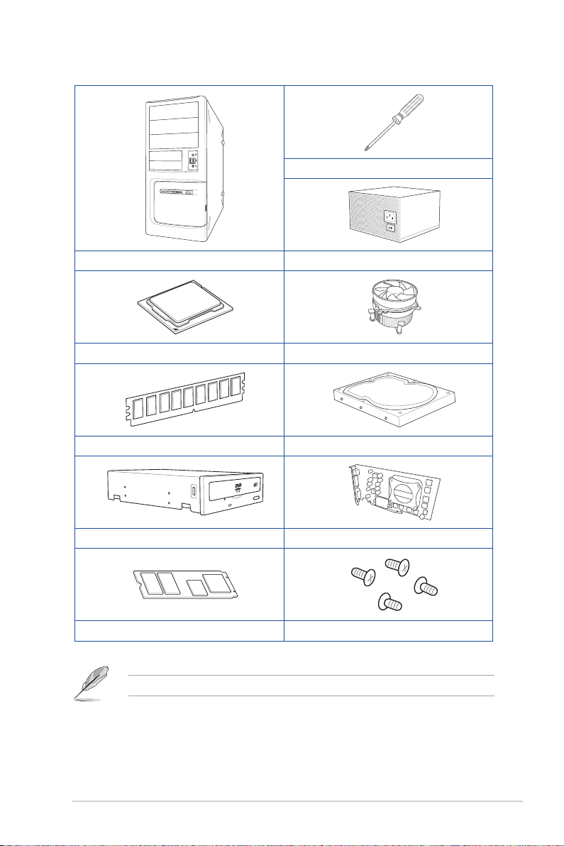
建立 PC 系統所需的其他工具與元件
Phillips(十字)螺絲刀
PC 機箱
Intel® LGA 1200 處理器 Intel® LGA 1200 兼容處理器風扇
DDR4 內存條 SATA 硬盤
SATA 光驅(選購) 顯卡(選購)
M.2 SSD 模塊(選購)
電源供應設備
一包螺絲
上表所列的工具與元件並不包含在主板包裝盒內。
xix
Page 20

xx
Page 21

第一章
1.1 主板安裝前
主板以及擴展卡都是由許多精密複雜的集成電路元件、集成性芯片等所構成。而這
些電子性零件很容易因靜電的影響而導致損壞,因此,在您動手更改主板上的任何設
定之前,請務必先作好以下所列出的各項預防措施。
• 在處理主板上的內部功能設定時,您可以先拔掉電腦的電源線。
• 為避免生成靜電,在拿取任何電腦元件時除了可以使用防靜電手環之
外,您也可以觸摸一個有接地線的物品或者金屬物品像電源外殼等。
• 拿取集成電路元件時請盡量不要觸碰到元件上的芯片。
• 在您卸除任何一個集成電路元件後,請將該元件放置在絕緣墊上以隔
離靜電,或者直接放回該元件的絕緣包裝袋中保存。
• 在您安裝或卸除任何元件之前,請確認 ATX 電源的電源開關是切換
到關閉(OFF)的位置,而最安全的做法是先暫時拔出電源的電源
線,等到安裝/卸除工作完成後再將之接回。如此可避免因仍有電力
殘留在系統中而嚴重損及主板、外圍設備、元件等。
ROG STRIX Z490-E GAMING 主板用戶手冊
1-1
Page 22
第一章
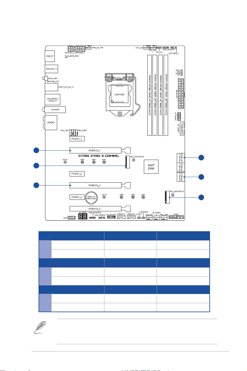
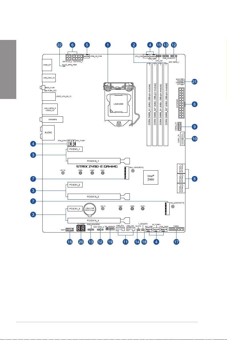
1.2 主板結構圖
1-2
第一章:產品介紹
Page 23

連接插槽/開關與跳線選擇區/插槽 頁數
1. CPU socket 1-4
2. DIMM slots 1-5
3. Expansion slots 1-7
4. Fan and Pump headers 1-9
5. VRM Heatsink Fan header 1-10
6. Power connectors 1-11
7. M.2 slot 1-12
8. SATA 6GB/s port 1-13
9. USB 3.2 Gen 2 Front Panel connector 1-14
10. USB 3.2 Gen 1 header 1-14
11. USB 2.0 header 1-15
12. AURA Addressable Gen2 header 1-16
13. AURA RGB header 1-17
14. Clear CMOS header 1-18
15. CPU Over Voltage jumper 1-19
16. Front Panel Audio header 1-19
17. System Panel header 1-20
18. Thermal Sensor header 1-21
19 Thunderbolt header 1-22
20. Q-Code LED 1-23
21. Q-LEDs 1-24
22. 8-pin Power Plug LED 1-24
第一章
ROG STRIX Z490-E GAMING 主板用戶手冊
1-3
Page 24
第一章
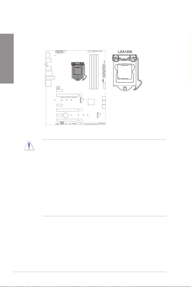
1. 中央處理器(CPU)
本主板具備一個 LGA1200 處理器插槽,本插槽是專為第十代 Intel® Core™、
Pentium® Gold 與 Celeron® 處理器所設計。
• 本插槽僅支持 LGA1200 處理器,請確認並安裝正確的處理器, 請
勿將其他處理器安裝於 LGA1200 插槽。
• 處理器只能以一個方向正確安裝,請勿強制將處理器設備插槽,以避
免弄彎處理器的針腳與處理器本身。
• 當您安裝 CPU 時,請確認所有的電源接口都已拔除。
• 在您購買本主板之後,請確認在插座上附有一個即插即用的保護蓋,
並且插座接點沒有彎曲變形。若是保護蓋已經丟失或是沒有保護蓋,
或者是插座接點已經彎曲,請立即與您的經銷商聯絡。
• 在安裝完主板之後,請將即插即用的保護蓋保留下來。只有 LG
A1200 插槽上附有即插即用保護蓋的主板符合 Return Merchandise
Au thori zatio n(RMA)的要求,華碩電腦才能為您處理產品的維修
與保修。
• 本保修不包括處理器插座因遺失、錯誤的安裝或不正確的卸除即插即
用保護蓋所造成的丟失。
1-4
第一章:產品介紹
Page 25

2. 系統內存
本主板配置有 4 組 DDR4(Double Data Rate 4)內存條插槽。
DDR4 內存插槽的缺口與 DDR、DDR2 或 DDR3 內存插 槽 不 同,請勿將
DDR、DDR2 或 DDR3 內存條插入 DDR4 插槽。
內存建議設定
第一章
ROG STRIX Z490-E GAMING 主板用戶手冊
1-5
Page 26

內存設定
您可以任意選擇使用 2GB、4GB、8GB、16G 與 32G 的 unbuffered and
non-ECC DDR4 內存條至本主板的內存插槽上。
第一章
您可以在 Channel A、Channel B 安裝不同容量的內存條,在雙通道設定
中,系統會檢測較低容量通道的內存容量。任何在較高容量通道的其他
內存容量,會被檢測為單通道模式運行。
• 默認的內存運行頻率是根據其 SPD(Serial Presence Detect)。在
默認狀態下,某些內存在超頻時的運行頻率可能會較供應商所標示的
數值為低。
• 在全負載或超頻設定下,內存條可能需要更佳的冷卻系統以維持運行
的穩定。
• 請安裝相同 CAS Latency 的內存條。為求最佳兼容性,建議您安裝
同廠牌、相同數據碼(D/C)版本的內存條。請先與供應商確認並購
買正確的內存條。
• 請訪問華碩網站查詢最新內存供應商列表(QVL)。
1-6
第一章:產品介紹
Page 27

3. 擴展插槽
安裝或卸除任何擴展卡之前,請暫時先將電腦的電源線拔出。如此可免
除因電氣殘留於電腦中而發生的意外狀況。
第一章
有關 VGA 設定建議與 Hyper M.2 設定,請參考下頁表格。
ROG STRIX Z490-E GAMING 主板用戶手冊
1-7
Page 28

第一章
VGA 設定建議
插槽說明 一張 VGA 兩張 VGA
2. PCIe 3.0 x16_1 x16 x8
4. PCIe 3.0 x16_2 N/A x8
• 當在運行 CrossFireX™ 或 SLI® 模式時,建議提供系統充足的電力供
應。
• 當在運行 CrossFireX™ 或 SLI® 模式時,請確認已連接 8-p in 與
4-pin 電源插座。
• 當您安裝多張顯卡時,建議您將機箱風扇的排線連接至機箱風扇插座
,以獲得更良好的散熱環境。
Hyper M.2 X16 系列卡設定
插槽說明
2. PCIe 3.0 x16_1 - x8+x4+x4
4. PCIe 3.0 x16_2 x4+x4 -
• Hyper M.2 X16 系列卡為選配,請另行購買。
• 當於 PCIe 3.0 x16_2 使用 1 至 2 個 intel® SSD on CPU 時,
PCIe3.0 x16_1 會以 x8 模式運行。
• 當使用 1 至 3 個 intel® SSD on CPU 時,PCIe 3.0 x16_2 將會關
閉。若您欲連接顯示屏,建議使用板端上的 V G A 連接端口或安裝
VGA 卡至 PCIe x16_3 插槽上,此時只會支持 x4 模式。
• 在 BIOS 程序設定下才可開啟 Hyper M.2 X16 系列卡。
最高支持 2 Intel® SSD on
CPU
最高支持 3 Intel® SSD on
CPU
1-8
第一章:產品介紹
Page 29

4. 風扇與泵插槽
將風扇與泵排線連接至風扇與泵插槽以冷卻系統。
• 千萬要記得連接風扇的電源,若系統中缺乏足夠的風量來散熱,那麼
很容易因為主機內部溫度逐漸昇高而導致死機,甚至更嚴重者會燒毀
主板上的電子元件。注意:這些插槽並不是單純的排針!不要將接針
套在它們的針腳上。
• 請確認排線完全插入中央處理器風扇插槽。
第一章
請將水冷卻套件的泵纜線連接到 AIO_PUMP 接口。
接口 最大電流 最大功率 默認速度 共享控制
CPU_FAN 1A 12W Q-Fan 控制 A
CPU_OPT 1A 12W Q-Fan 控制 A
CHA_FAN1 1A 12W Q-Fan 控制 CHA_FAN2 1A 12W Q-Fan 控制 VRM_HS_FAN 1A 12W Q-Fan 控制 AIO_PUMP 1A 12W 全速 M.2_FAN 1A 12W Q-Fan 控制 W_PUMP+ 3A 36W 全速 -
ROG STRIX Z490-E GAMING 主板用戶手冊
1-9
Page 30

第一章
5. VRM 散熱器風扇接口
VR M 散熱器風扇接口用來將 VRM 散熱器風扇連接至集成散熱器上。您也可
以在風扇支架上安裝 V R M 風扇後,再將其連接至 VRM 散熱器接口上,以利
VRM 溫度過高時冷卻 VRM。
欲了解更多關於安裝風扇支架的相關細節,請參考第二章 安裝附加冷卻
套件 一節的說明。
1-10
第一章:產品介紹
Page 31

6. 電源插槽
這些電源插槽用來連接主板電源。電源所提供的連接插頭已經過特別設計,只
能以一個特定方向插入主板上的電源插槽。找到正確的插入方向後,僅需穩穩地
將之套進插槽中即可。
請確認已連接 8-pin 電源插頭。
第一章
•
建議您使用與 2.0 規格(或更高)的 ATX 12V 兼容的電源(PSU)
,才能提供至少 350W 高功率的電源,以供應系統足夠的電源需求
。
• 如果您想要安裝其他的硬件設備,請務必使用較高功率的電源以提供
足夠的設備用電需求。若電源無法提供設備足夠的用電需求,則系統
將會變得不穩定或無法開啟。
• 若是您想要安裝兩張或更多的高級 PCIe x16 顯卡,請使用 1000 瓦
以上的電源以確保運行穩定。
ROG STRIX Z490-E GAMING 主板用戶手冊
1-11
Page 32

第一章
7. M.2 插槽
這些插槽用來安裝 M.2 SSD 模塊。
• M.2_1 插槽支持 PCIe 3.0 x4 與 SATA 模式 Key M 設計與 2242 /
2260 / 2280 / 22110 類型存儲設備。
• M.2_2 插槽支持 PCIe 3.0 x4 模式 Key M 設計與 2242 / 2260 /
2280 / 22110 類型存儲設備。
• 當 M.2_1 插槽以 SATA 模式運行時,SATA6G_2 將會關閉。
• M.2_2 與 SA TA6G_56 插槽共享帶寬。當 M.2_2 運行時,
SATA6G_56 將會關閉。
• M.2 插槽支持 IRST
(Intel® 快速保存技術)
。
1-12
第一章:產品介紹
M.2 SSD 模塊為選購配備,請另行購買。
Page 33

8. SATA 6Gb/s 設備連接插槽
這些插槽可支持使用 SATA 6Gb/s 排線來連接 SATA 6Gb/s 硬盤。
若您安裝了 SATA 硬盤,您可以通過內置的 Intel® Z490 芯片組來創建
RAID 0、RAID 1、RAID 5 與 RAID 10 磁盤陣列。
• 這些插槽的默認值為 [A H CI Mode],若您想要使用這些插槽來建構
SATA RAID 功能,請將 BIOS 程序中的 SATA Mode 項目設定為
[Intel RST Premium (RAID)]。
• 當 M.2_1 插槽以 SATA 模式運行時,SATA6G_2 將會關閉。
• M.2_2 與 SA TA6G_56 插槽共享帶寬。當 M.2_2 運行時,
SATA6G_56 將會關閉。
• 在創建 RAID 設定時,請參考 RAI D 設定用戶手冊(RAID
Configuration Guide)章節中的相關說明。您可以至華碩官網下載此
手冊。
第一章
ROG STRIX Z490-E GAMING 主板用戶手冊
1-13
Page 34

第一章
9. USB 3.2 Gen 2 前面板連接插槽
這個插槽用來連接 USB 3.2 Gen 2 模塊以擴展 USB 3.2 Gen 2 模塊。USB 3.2
Gen 2 的數據傳輸率最高可達 10 Gbps。
USB 3.2 Gen 2 模塊為選購配備,請另行購買。
10. USB 3.2 Gen 1 連接插槽
這個插槽用來連接 U S B 3.2 Gen 1 模塊,可在前面板或後側連接端口擴展
USB 3.2 Gen 1 模塊。當您安裝 USB 3.2 Gen 1 模塊,可以享受最高 5 Gb/s 數
據傳輸率。
1-14
第一章:產品介紹
USB 3.2 Gen 1 模塊為選購配備,請另行購買。
Page 35

11. USB 2.0 連接插槽
這些 USB 擴展套件排線插槽支持 USB 2.0 規格,將 USB 模塊排線連接至本
插槽,然後將模塊安裝到機箱後側面板中開放的插槽。這些 U S B 插槽與 USB
2.0 規格兼容,並支持傳輸速率最高達 480 Mb/s。
請勿將 1394 排線連接到 USB 插槽上,這麼做可能會導致主板的丟失。
USB 2.0 模塊為選購配備,請另行購買。
第一章
ROG STRIX Z490-E GAMING 主板用戶手冊
1-15
Page 36

第一章
12. AURA 可定址 Gen2 燈條接口
這些可定址 Gen2 燈條插槽可用來個別連接可定址 RGB WS2812B 指示燈條
或基於 WS2812B 的指示燈條。
可定址 G e n2 接口支持標準 W S2812S B 可定址 R G B LE D 指示燈條
(5V/Data/Ground),燈條總輸出電流限制為 3A(5V),此板子所有
可定址接口加總最多支持 500 顆 LED 燈。
1-16
第一章:產品介紹
在您安裝或刪除任何元件之前,請確認 ATX 電源的電源開關是切換到關
閉(OFF)的位置,而最安全的做法是先暫時拔出電源的電源線,等到安
裝/刪除工作完成後再將之接回。如此可避免因仍有電力殘留在系統中而
嚴重損及主板、外圍設備、元件等。
• 實際的光線效果與顏色視 LED 指示燈條而定。
• 若您的指示燈條未亮起,請檢查 R G B LED 指示燈延長線與指示燈
條是否連接在正確位置、插座(5V)是否與接口(5V)對齊至主板
上。
• 可定址 RGB LED 指示燈條僅會於操作系統下亮起。
• 可定址 RGB LED 指示燈條為選購配備,請另行購買。
Page 37

13. AURA RGB 燈條接口
這些接口是用來連接 RGB LED 燈條。
AURA RGB 接口支持 5050 RGB 多彩 LED 燈條(12V/G/R/B),燈條
總輸出電流限制為 3A(12V)。
在安裝或卸除任何零件之前,請確認已切斷 A T X 電源或是已拔除電源
線,否則將對主板、周邊配件或零件造成嚴重損害。
第一章
• 實際的亮度與色彩會依 LED 燈條而有所差異。
• 若您的指示燈條未亮起,請檢查 RGB 指示燈延長線與指示燈條是否
連接在正確位置、插座(12V)是否與接口(12V)對齊至主板上。
• LED 燈條僅會在操作系統下亮起。
• LED 燈條為選購配備,請另行購買。
ROG STRIX Z490-E GAMING 主板用戶手冊
1-17
Page 38

第一章
14. Clear CMOS 按鈕
按下這個按鈕以清除 C M OS 中的實時時鐘(R TC)隨機存取內存,其包含日
期、時間、系統密碼與系統設定參數。
想要清除這些數據,可以依照下列步驟進行:
1. 關閉電腦電源,拔掉電源線。
2. 將金屬物或接針由 [1-2] 短路時約五∼十秒鐘。
3. 插上電源線,開啟電腦電源。
4. 當啟動步驟正在進行時按著鍵盤上的 <Del> 鍵進入 BIOS 程序畫面重新設
定 BIOS 數據。
1-18
第一章:產品介紹
除了清除實時時鐘隨機存取內存之外,請勿使針腳短路,因為短路或置
放跳線帽可能會導致系統啟動失敗。
若上述方法無效,請卸除主板上的內置電池,再將接針卸除一次來清除
CMOS 配置數據。在 CMOS 配置數據清除後,請將電池重新裝回主板。
Page 39

15. CPU 超壓接針
這個接針可讓您依照安裝的處理器類型,設定較高的處理器電壓以獲得更有彈
性的超頻系統。若要獲得更多的處理器電壓,將接針針腳設為 2-3,若要恢復默
認的處理器電壓設定,將接針針腳移回 1-2 的位置。
16. 前面板音頻排針
這組音頻外接排針供您連接到前面板的音頻排線,除了讓您可以輕鬆地通過主
機前面板來控制音頻輸入/輸出等功能,並且支持 HD Audio 音頻標準。將前面板
音頻輸出/輸入模塊的連接排線之一端連接到這個插槽上。
第一章
建議您將支持高保真(high definition)音頻的前面板音頻模塊連接到這
組排針,如此才能獲得高保真音頻的功能。
ROG STRIX Z490-E GAMING 主板用戶手冊
1-19
Page 40

第一章
17. 系統控制面板連接排針
這組連接排針包含數個連接到電腦主機前面板的功能接針。
• 系統電源指示燈連接排針(PLED)
這組 2-p in 排針可連接到電腦主機面板上的系統電源指示燈。在您啟動電腦並
且使用電腦的情況下,該指示燈會持續亮著;而當指示燈閃爍亮著時,即表示電
腦正處於睡眠模式中。
• 硬盤動作指示燈號接針(HDD_LED)
您可以連接這組 2-p in 排針到電腦主機面板上的硬盤動作指示燈號,如此一旦
硬盤有存取動作時,指示燈隨即亮起。
• 機箱喇叭連接排針(SPEAKER)
這組 4-p in 排針連接到電腦主機機箱中的喇叭。當系統正常啟動便可聽到嗶嗶
聲,若啟動時發生問題,則會以不同長短的音調來警示。
• 電源/軟關機開關連接排針(PWRBTN)
這組 3-1 p i n 排針連接到電腦主機面板上控制電腦電源的開關。您可以根據
BIOS 程序或操作系統的設定,來決定當按下開關時電腦會在正常運行和睡眠模
式間切換,或者是在正常運行和軟關機模式間切換。若要關機,請持續按住電源
開關超過四秒的時間。
• 重置開關連接排針(RESET)
這組 2-pin 排針連接到電腦主機面板上的 Reset 開關。可以讓您在不需要關掉
電腦電源即可重新啟動,尤其在系統死機的時候特別有用。
• 機箱開啟警告排針 (CHASSIS)
這組 2-p in 排針提供給設計有機箱開啟檢測功能的電腦主機機箱之用。此外,
尚須搭配一個外接式檢測設備譬如機箱開啟檢測感應器或者微型開關。在本功能
啟用時,若您有任何移動機箱元件的動作,感應器會隨即檢測到並且送出一信號
到這組接針,最後會由系統記錄下來這次的機箱開啟事件。
1-20
第一章:產品介紹
Page 41

18. 溫度感應線連接排針
此插座為連接溫度感應線,可以讓您監控主板重要元件和連接設備的溫度。連
接溫度感應器排線,然後將感應器放置在這些設備或主板的元件上面,便可進行
檢測其溫度。
溫度感應線為選購配備,請另行購買。
第一章
ROG STRIX Z490-E GAMING 主板用戶手冊
1-21
Page 42

第一章
19. Thunderbolt 接口
這個插槽用來連接附加的 Thunderbolt I/O 卡,以支持 Intel Thunderbolt 技術
,您可以在一個串接設定中連接最高達六個支持 Thunderbolt 的設備與一個支持
DisplayPort 的顯示設備。
附加的 Thunderbolt I/O 卡與 Thunderbolt 排線為選購配備,請另行購買
。
1-22
第一章:產品介紹
Page 43

20. Q-Code 指示燈
Q-Code 指示燈設計為 2 位顯示,用來得知系統狀態。
• Q-Cod e 指示燈的錯誤碼提供最有可能發生錯誤的原因,以作為排除
故障的問題點。實際情況可能會因個案的不同而異。
• 欲了解更多相關細節,請參考 附錄 中的 Q-Code 列表。
第一章
ROG STRIX Z490-E GAMING 主板用戶手冊
1-23
Page 44

第一章
21. Q 指示燈
Q 指示燈從主板啟動後依序查看 CPU、內存、顯卡與啟動設備狀態。當發現
錯誤時,在該項目旁的指示燈則會亮燈直到問題解決。通過直覺的方式提供這項
友善的設計,能在短短幾秒內找到問題點。
Q 指示燈提供最有可能的錯誤原因以幫助找到問題點。實際的原因將視
情況而異。
22. 8-pin 電源插座指示燈
當 8-pin 電源插座指示燈亮起時表示未連接 8-pin 電源插座。
1-24
第一章:產品介紹
Page 45

第二章
2.1 創建您的電腦系統
本章節的圖標只能參考,主板的結構可能會隨著型號而有所不同,但是
安裝的步驟仍然是相同的。
2.1.1 安裝中央處理器
• 本插槽僅支持 LGA1200 處理器,請確認並安裝正確的處理器, 請
勿將其他處理器安裝於 LGA1155、LGA1156 與 LGA1151 插槽。
• 請記下開/關雙固定扳手的順序,依照印在處理器金屬密封艙口或是
下列圖標的說明安裝處理器,當處理器放置完成並將固定扳手扣好後
,塑料保護蓋會自動彈出。
ROG STRIX Z490-E GAMING 主板用戶手冊
2-1
Page 46

第二章
2-2
第二章:硬件設備信息
Page 47

2.1.2 安裝冷卻系統
安裝散熱片與風扇
在安裝冷卻系統之前若有需
要,請先將處理器與處理器
冷卻系統塗上散熱膏。
第二章
ROG STRIX Z490-E GAMING 主板用戶手冊
2-3
Page 48

第二章
安裝 AIO 冷卻器
當您使用這類型的處理器風扇時,只能將卸除螺絲與固定模塊。請勿卸
除底部的板子。
AIO_PUMP/
W_PUMP+
2-4
第二章:硬件設備信息
CPU_FAN
CPU_OPT
Page 49

2.1.3 安裝內存條
第二章
取出內存條
ROG STRIX Z490-E GAMING 主板用戶手冊
2-5
Page 50

2.1.4 安裝 M.2
1
第二章
1
3
4
3
4
5
3
3
OPTIONAL
2
1
• 當安裝單面 M.2 存
儲設備時,此步驟為
選擇性操作。在安裝
單面 M.2 存儲設備
前,請先確認已安裝
產品隨附的 M.2 橡
膠墊。
• 當您安裝雙面 M.2
存儲設備時,不需要
再安裝產品隨附的
M.2 橡膠墊。原先已
黏貼於卡上的橡膠墊
即可適用於雙面 M.2
存儲設備。
2-6
第二章:硬件設備信息
Page 51

6
7
6
10
9
10
10
8
9
10
8
第二章
ROG STRIX Z490-E GAMING 主板用戶手冊
2-7
Page 52

12
12
11
12
第二章
M.2 為選購配備,請另行購買。
2-8
第二章:硬件設備信息
Page 53

2.1.5 安裝附加冷卻套件
2
4
1
4
3
5
5
6
VRM_HS_FAN
7
8
• 於超頻期間使用高性能設定時,請確認已將隨附的風扇安裝至 MOS
風扇支架上。
• 您可以安裝 12V (1A、12W) 40mm x 40mm 的風扇。
• 您可以於安裝風扇支架時,根據自己的喜好調整風扇支架的高度。
• 請使用產品隨附的螺絲來安裝風扇。
第二章
ROG STRIX Z490-E GAMING 主板用戶手冊
2-9
Page 54

第二章
2.1.6 安裝主板
1. 將主板放入機箱,並確認後側 I/O 連接端口對齊機箱的後側 I/O 面板。
2. 將 9 個螺絲放入主板上的螺絲孔並旋轉鎖緊,以確保將主板鎖至機箱。
2-10
第二章:硬件設備信息
請勿將螺絲鎖得太緊!否則容易導致主板的印刷電路板生成龜裂。
Page 55

2.1.7 安裝 ATX 電源
第二章
或
• 為避免主板在重度使用下造成過熱,請勿單獨連接 4-pin 電源插座。
• 請確實連接 8-pin 電源插座或是同時連接 8-pin 與 4-pin 電源插座。
ROG STRIX Z490-E GAMING 主板用戶手冊
與
2-11
Page 56

第二章
2.1.8 安裝 SATA 設備
或
2-12
第二章:硬件設備信息
Page 57

2.1.9 安裝前面板輸出/輸入連接端口
安裝前面板連接插槽
安裝 USB 3.2 Gen 1 連接插槽
安裝 USB 3.2 Gen 2 連接插槽
USB 3.2 Gen 2
本插槽僅能以一個方向
插入。請將插頭壓入插
槽直到卡入定位。
第二章
安裝 USB 2.0 連接插槽
USB 3.2 Gen 1
安裝前面板音頻連接插槽
USB 2.0
AAFP
ROG STRIX Z490-E GAMING 主板用戶手冊
2-13
Page 58

第二章
2.1.10 安裝擴展卡
安裝 PCIe x16 顯卡
安裝 PCIe x1 顯卡
2-14
第二章:硬件設備信息
Page 59

安裝 ThunderboltEX 3-TR 卡
USB
Type-C® 連
接端口連接
至 Thunder-
bolt 設備
主板或 VGA
卡上將
MiniDP 輸入
連接端口連
接至 DP 輸
出連接端口
請確認已從 PCH 中安裝 ThunderboltEX 3-TR 卡至 PCIe 插槽。
• 選項 6 為選擇性步驟,若您希望使用 USB Type-C® 連接端口
Thunderbolt 快速充電功能為 5V 或更高設備充電時,請連接 6-p in
PCIe 電源插座。ThunderboltEX 3-TR 卡最高可支持 100W 快速充電
。
• 當 6-pin PCIe 電源插座連接時,TypeC_1 連接端口最高可支持 20V
設備;TypeC_2 連接端口最高可支持 9V 設備。
• Thunderbolt 卡為選購配備,請另行購買。
6-pin PCIe 電源連接端口
USB 2.0 接口
Thunderbolt 接口
第二章
ROG STRIX Z490-E GAMING 主板用戶手冊
2-15
Page 60

第二章
2.1.11 安裝 Wi-Fi 天線
安裝華碩 2x2 雙頻 W-Fi 天線
將包裝盒內附的華碩 2x2 雙頻 W-Fi 天線連接至機箱後側面板的上面兩個 Wi-Fi 連
接端口。
• 請確認華碩 2x2 雙頻 W-Fi 已經確實安裝至 Wi-Fi 連接端口。
• 請將天線與所有人員保持至少 20 厘米的距離。
2-16
第二章:硬件設備信息
上圖只能參考,I/O 連接端口可能會依照您所購買的型號而有不同,但是
Wi-Fi 天線安裝程序適用於任一型號。
Page 61

2.2 BIOS 更新應用程序
BIOS Flashback
BI O S Flas hbac k™ 提供最簡單更新 BIOS 的方法。用戶可以輕鬆嘗試使用新的
BIOS 版本來進行超頻,不需要進入 BIOS 或操作系統,只要插入 USB 存儲設備然後
按下 BIOS Flashback 按鈕三秒鐘,BIOS 程序就會自動在待機狀態下更新。
請依照以下步驟使用 BIOS Flashback™:
1. 將 USB 存儲設備插入 Flashback™ 連接端口。
2. 訪問 https://www.asus.com/support/ 以下載適用於本主板的最新 BIOS 版本。
3. 將文件重新命名為 SZ490E.CAP,或是開啟 BIOSRenamer.exe 應用程序以自動
將文件重新命名,接著複製至您的 USB 存儲設備。
4. 將電腦關機。
5. 按下主板上的 BIOS Flashback™ 按鈕約 3 秒鐘直到 Flashback™ 指示燈閃爍 3
次,表示 BIOS Flashback™ 功能已經啟動。
™
建議您使用 USB 2.0 存儲設備來保存最新的 BIOS,可以獲得更好的兼容
性與穩定性。
當您於兼容 BIOS FlashBack™ 的主板下載文件時,BIOSRenamer.exe 應
用程序與您的 BIOS 文件會一同壓縮。
第二章
BIOS Flashback™ 按鈕BIOS Flashback™ 連接端口
6 當指示燈停止閃爍時,即表示更新已經完成。
若要在 B I OS 設定中使用更多的 B I OS 更新程序,請參考第三章 更新
BIOS 程序 一節的說明。
• 在更新 BIOS 過程中,請勿將外接式存儲設備、電源拔除,也請勿按
下 CLR_CMOS 按鈕,否則更新過程將會被中斷。若是發生更新中斷
的狀況,請依照上述步驟重新進行更新直至更新完成為止。
• 若燈號閃爍超過五秒鐘,並轉變為持續亮著,表示 BIOS Flashback™
動作沒有正確被運行,可能造成的原因有二,分別為:1. 外接式存
儲設備安裝不正確;2. 不正確的文件名稱或不兼容的文件格式,若
是發生這種情況,請重新啟動系統來關閉燈號。
• 更新 BIOS 可能會有風險,若是在更新過程中發生 BIOS 程序丟失導
致系統無法重新啟動時,請與當地的客服中心聯絡尋求協助。
ROG STRIX Z490-E GAMING 主板用戶手冊
2-17
Page 62

2.3 主板後側與音頻連接端口
2.3.1 後側面板連接端口
第二章
後側面板連接端口
1. DisplayPort 連接端口
2. USB 2.0 連接端口 5、6、7 與 12
3. USB 3.2 Gen 1 Type-A 連接端口 9 與 10
4. Intel® I225-V 網絡端口
5. Wi-Fi 6 (802.11 a/b/g/n/ac/ax)、藍牙 V5.1
6. HDMI™ 連接端口
7. BIOS FlashBack™ 按鈕
8. USB 3.2 Gen 2 Type-A 連接端口 1 與 2
9. USB 3.2 Gen 2 Type-A 連接端口 3
10. USB 3.2 Gen 2 Type-C® 連接端口 C4
11. 光纖 S/PDIF 輸出端口
12. 鍍金音頻輸出/輸入接口*
*: 請參考下頁表格中網絡連接端口指示燈與音頻連接端口的定義。
• 強烈建議您將 USB 3.2 Gen 1 設備連接至 USB 3.2 Gen 1 連接端
口;USB 3.2 Gen 2 設備連接至 USB 3.2 Gen 2 連接端口,才能讓
設備獲得更快更好的性能表現。
• 由於 Intel 芯片組的設計,所有連接至 USB 3.2 Gen 1 連接端口的
USB 設備皆由 xHCI 控制器控制。部分舊版的 USB 設備須更新固件
以獲得更好的兼容性。
2-18
第二章:硬件設備信息
Page 63

* 2、4、5.1 或 7.1 聲道音頻設定
接口 耳機/2 聲道 4 聲道 5.1 聲道 7.1 聲道
淺藍色 聲音輸入端 聲音輸入端 聲音輸入端 側置喇叭輸出
草綠色 聲音輸出端 前置喇叭輸出 前置喇叭輸出 前置喇叭輸出
粉紅色 麥克風輸入 麥克風輸入 麥克風輸入 麥克風輸入
橘色 – –
黑色 – 後置喇叭輸出 後置喇叭輸出 後置喇叭輸出
中央聲道/重低音
喇叭輸出
中央聲道/重低音
喇叭輸出
2.3.2 音頻輸出/輸入連接圖標說明
音頻輸出/輸入連接端口
連接耳機與麥克風
連接立體聲喇叭
橘色
黑色
淺藍色
草綠色
粉紅色
第二章
ROG STRIX Z490-E GAMING 主板用戶手冊
2-19
Page 64

第二章
連接 2 聲道喇叭
連接 4 聲道喇叭
連接 5.1 聲道喇叭
2-20
第二章:硬件設備信息
Page 65

連接 7.1 聲道喇叭
第二章
ROG STRIX Z490-E GAMING 主板用戶手冊
2-21
Page 66

第二章
2.4 第一次啟動電腦
1. 確認所有排線與接腳都接妥,然後蓋上機箱的外蓋。
2. 確定所有的開關都已關閉。
3. 將電源線接上機箱背面的電輸入插座。
4. 情況許可的話,最好將電源線路上加接突波吸收/保護器。
5. 您可以先開啟以下周邊的電源:
a. 顯示器
b. 外部存儲設備(從串連的最後設備開始)
c. 系統電源
6. 送電之後,機箱面板上應該會有電源指示燈亮起才對。如果是使用 A TX 電源的
話,必須等到面板按鈕被觸碰後才會啟動電源,電源指示燈此時才會亮起。如果
您的電腦符合綠色省電標準,已隨時準備可以進入省電模式的話,顯示器指示燈
也會亮起。如果啟動過程一切順利的話,不久就可以在顯示器上看到畫面了,如
果送電之後超過 30 秒而畫面未有動靜的話,表示電腦的設定尚有問題存在,請
再進一步地的檢查各項動作,如果還是不行,就需要向廠商求助了!
BIOS 嗶聲所代表的意義
嗶聲 代表意義
檢測到 VGA 顯卡
一短嗶聲
一連續嗶聲後跟隨兩短嗶聲,暫停一
下然後重複
一連續嗶聲後跟隨三短嗶聲 沒有 VGA 顯卡被檢測到
一連續嗶聲後跟隨四短嗶聲 硬件組件失效
快速啟動設定為關閉
沒有鍵盤被檢測到
沒有內存被檢測到
7. 在電源開啟之後可按下 <Del> 鍵以進入 BIOS 的設定模式,詳細設定方法請看本
用戶手冊的第三章部份。
2.5 關閉電源
當系統在啟動狀態,壓著電源開關少於 4 秒鐘,系統會根據 BIOS 的設定,進入睡
眠或軟啟動模式;若是壓著電源開關多於 4 秒,不論 BIOS 的設定為何,系統則會直
接進入軟啟動模式。
2-22
第二章:硬件設備信息
Page 67

第三章
請參考 www.asus.com/support 以了解更多關於 BIOS 與 RAID 設定的
相關信息。
3.1 認識 BIOS 程序
華碩全新的 UEFI BIOS 是可延伸固件界面,符合最新的 UEFI 架構,這
個友善的使用界面,跳脫常規使用鍵盤輸入 BIOS 方式,提供更有彈性與
更便利的鼠標控制操作。您可以輕易地使用新的 UEFI BIOS,如同操作您
的操作系統般順暢。在本用戶手冊中的「BIO S」一詞除非特別說明,所
指皆為「UEFI BIOS」。
BIOS(Basic Input and Output System;基本輸出入系統)用來保存系統啟動時所
需要的硬件設定,例如存儲設備設定、超頻設定、高級電源管理與啟動設定等,這些
設定會保存在主板的 CMOS 中,在正常情況下,默認的 BIOS 程序設定提供大多數
使用情況下可以獲得最佳的運行性能,建議您不要更改默認的 BIOS 設定,除了以下
幾種狀況:
• 在系統啟動期間,螢幕上出現錯誤信息,並要求您運行 BIOS 程序設定。
• 安裝新的系統元件,需要進一步的 BIOS 設定或更新。
不適當的 BIOS 設定可能會導致系統不穩定或啟動失敗,強烈建議您只有
在受過訓練專業人士的協助下,才可以運行 BIOS 程序設定的更改。
•
下載或更新 BIOS 文件時,請將文件名稱更改為 SZ490E.CAP 給本
主板使用。
• BIOS 設定與選項會依不同的 BIOS 版本而有所差異。請參考最新BIOS
版本 的 設 定 及 選 項。
ROG STRIX Z490-E GAMING 主板用戶手冊
3-1
Page 68

第三章
3.2 BIOS 設定程序
使用 BIOS Setup(BIOS 設定)功能可以更新 BIOS 或設定其參數。BIOS 設定畫
面包含導覽鍵與簡要的畫面輔助說明,以指示您使用 BIOS 設定程序。
在啟動電腦時進入 BIOS 設定程序
若要在啟動電腦時進入 BIOS 設定程序,請在系統仍在自我測試(POST,PowerOn Self Test)時,按下 <Delete> 或 <F2> 鍵,就可以進入設定程序,如果您超過時
間才按 <Delete> 或 <F2> 鍵,則 POST 程序會自動繼續運行啟動測試。
在 POST 後進入 BIOS 設定程序
請依照以下步驟在 POST 後進入 BIOS 設定程序:
• 同時按下 <Ctrl> + <Alt> + <Delete> 鍵。
• 按下機箱上的 reset 鍵重新啟動。
• 按下電源按鈕關機後再重新啟動。請在使用上述兩個方法後仍無法進入 B I OS 設
定程序時,再使用此方法。
在運行以上任一程序後,按下 <Delete> 鍵進入 BIOS 程序。
• 若您想在 BIOS 設定程序中使用鼠標操控,請先確認已將鼠標連接至
主板。
• BIOS 程序的出廠默認值可讓系統運行處於最佳性能,但是若系統因
您改變 BI O S 程序而導致不穩定,請讀取出廠默認值來保持系統的
穩定。請選擇 Exit 菜單中的 Load Optimized Defaults 項目或按下
<F5> 鍵。
• 若是更改 BIOS 設定後啟動失敗,請試著使用 Clear CMOS,然後將
主板的設定值恢復為默認值。
• BIOS 設定程序不支持使用藍牙設備。
BIOS 菜單畫面
本主板的 BIOS 設定程序提供您 EZ Mode 和 Advanced Mode 兩種模式。您可以
在 啟動菜單(Boot menu)中的 Setup Mode 切換模式,或按 <F7> 鍵進行切換。
3.3 EZ Update
EZ Update 是一套可以讓您在 Windows® 操作系統下,用來更新主板 BIOS 文件的
應用程序。
• 在使用 EZ Update 之前,請先確認您已經通過內部網絡對 外 連 接,或
者通過互聯網服務供應商(ISP)所提供的連線方式連接到互聯網。
• 這個程序可以在主板附贈的驅動程序及應用程序光盤中找到。
3-2
第三章:BIOS 程序設定與 RAID 支持
Page 69

3.4 華碩 EZ Flash 3
華碩 EZ Flash 3 程序讓您在未進入操作系統前即能輕鬆的更新 BIOS 程序。
請讀取出廠默認值來保持系統的穩定。請選擇 Exit 菜單中的 Load
Optimized Defaults 項目或按下 <F5> 鍵。
請依照以下步驟通過 USB 更新 BIOS 程序:
• 本功能僅支持採用 FAT 32/16 格式的單一磁區 U 盤。
• 當更新 BIOS 時,請勿關閉或重置系統以避免系統啟動失敗。
1. 將保存有最新的 BIOS 文件的 U 盤插入 USB 連接端口。
2. 進入 BIOS 設定程序的 Advanced Mode,選擇 Tool > ASUS EZ Flash 3 Utility,
接著請按下 <Enter> 鍵。
3. 請使用 <Tab> 鍵操控 Drive 區域。
4. 請利用上/下方向鍵找到存放有最新 B IOS 文件的 U 盤,接著請按下 <Ent e r>
鍵。
5. 請使用 <Tab> 鍵操控 Folder Info 區域。
6. 請利用上/下方向鍵找到 U 盤中最新的 BIOS 文件,接著請按下 <Enter> 鍵開始
BIOS 更新作業。當 BIOS 更新作業完成後請重新啟動電腦。
ROG STRIX Z490-E GAMING 主板用戶手冊
第三章
3-3
Page 70

3.5 華碩 CrashFree BIOS 3
華碩最新自行研發的 CrashFree BIOS 3 工具程序,讓您在當 BIOS 程序和數據被
病毒入侵或丟失時,可以輕鬆的從驅動程序及應用程序光盤,或是從含有最新或原始
的 BIOS 文件的 U 盤中恢復 BIOS 程序的數據。
在驅動程序及應用程序光盤中的 BIO S 程序版本可能會比官方網站上的
BIOS 程序版本舊,若是想要使用更新的 BIOS 程序,請至 https://www.
asus.com/support/ 網站下載,並保存在便攜存儲設備中。
恢復 BIOS 程序
請依照下列步驟使用應用程序光盤恢復 BIOS 程序:
1. 啟動系統。
2. 將主板的應用程序光盤放入光驅,或是將含有最新或原始的 BIOS 文件的 U 盤插
入 USB 連接端口。
3. 接著工具程序便會自動檢查光盤或存儲設備中是否存有 BIOS 文件。當 搜索到
BIOS 文件後 ,工 具 程序會開始讀取 BIOS 文件並自動進入華碩 EZ Flash 3 程序。
4. 系統需要您進入 B IOS 程序來恢復 BIOS 設定,為了確保系統的兼容性與穩定
性,建議您按下 <F5> 按鍵來載入 BIOS 程序的默認值。
當更新 BIOS 時,請勿關閉或重置系統以避免系統啟動失敗。
第三章
3-4
第三章:BIOS 程序設定與 RAID 支持
Page 71

3.6 RAID 功能設定
本主板支持 Intel® Rapid Storage 快速保存技術,可支持 RAID 0、RAID 1、RAID
5 與 RAID 10 磁盤陣列的設定。
更多關於 RAID 的設定,請至華碩技術支持網站 https://www.asus.com/
support 參考 RAID 設定用戶手冊(RAID Configuration Guide)中的詳
細說明。
RAID 定義
RAID 0 的主要功能為「Data striping」,即區塊延展。其運行模式是將磁盤陣列
系統下所有硬盤組成一個虛擬的大硬盤,而數據存取方式是平均分散至多顆硬盤,是
以並行的方式讀取/寫入數據至多顆硬盤,如此可增加存取的速度,若以二顆硬盤所
建構的 RAID 0 磁盤陣列為例,傳輸速度約為陣列中轉速最慢的硬盤的二倍速度。整
體而言,RAID 0 模式的磁盤陣列可增加數據傳輸的性能與速率。
RAID 1 的主要功能為「Data Mirroring」,即數據映射。其運行模式是將磁盤陣列
系統所使用的硬盤,建立為一組映射對應(Mirrored Pair),並以平行的方式讀取/寫
入數據至多顆硬盤。而寫入至各個硬盤的數據是完全一樣的,在讀取數據時,則可由
本組內所有硬盤同時讀出。而 RAID 1 模式的磁盤陣列最主要就是其容錯功能(fault
tolerance),它能在磁盤陣列中任何一顆硬盤發生故障的情況時,其它硬盤仍可以繼
續動作,保持系統不中斷運行。即使陣列中某一顆硬盤丟失時,所有的數據仍會完整
地保留在磁盤陣列的其它硬盤中。
RA ID 5 的主要功能為將數據與驗證信息加以延展,分別記錄到三部或以上的硬盤
中。而 RAID 5 陣列設定的優點,包括有取得更理想的硬盤性能、具備容錯能力,與
更大的保存容量。RA I D 5 陣列模式最適合的使用範疇,可用於交叉處理作業、數據
庫應用、企業資源的規劃,與商業系統的應用。這類型的陣列模式,最少需要三部硬
盤方可進行設定。
RAID 10 的主要功能為「Data striping」+「Data Mirroring」,也就是集 RAID 0
與 RAI D 1 之所長,不但可運用到 RAID 0 模式所提供的高速傳輸速率,也保有了
RA I D 1 模式的數據容錯功能,讓您不但享有高速的數據傳輸功能,對於數據的保存
也無後顧之憂。
ROG STRIX Z490-E GAMING 主板用戶手冊
第三章
3-5
Page 72

第三章
3-6
第三章:BIOS 程序設定與 RAID 支持
Page 73

Q-Code 列表
Code 說明
00
01
02
03
04
06
07
08
09
0B
0C – 0D
0E
0F
10
11 – 14
15 – 18
19 – 1C
2B – 2F
30
31
32 – 36
37 – 3A
3B – 3E
4F
50 – 53
54
55
56
57
58
59
5A
5B
5C – 5F
Not used
Power on. Reset type detection(soft/hard).
AP initialization before microcode loading
System Agent initialization before microcode loading
PCH initialization before microcode loading
Microcode loading
AP initialization after microcode loading
System Agent initialization after microcode loading
PCH initialization after microcode loading
Cache initialization
Reserved for future AMI SEC error codes
Microcode not found
Microcode not loaded
PEI Core is started
Pre-memory CPU initialization is started
Pre-memory System Agent initialization is started
Pre-memory PCH initialization is started
Memory initialization
Reserved for ASL(see ASL Status Codes section below)
Memory Installed
CPU post-memory initialization
Post-Memory System Agent initialization is started
Post-Memory PCH initialization is started
DXE IPL is started
Memory initialization error. Invalid memory type or incompatible
memory speed
Unspecified memory initialization error
Memory not installed
Invalid CPU type or Speed
CPU mismatch
CPU self test failed or possible CPU cache error
CPU micro-code is not found or micro-code update is failed
Internal CPU error
Reset PPI is not available
Reserved for future AMI error codes
附錄
(表格續下頁)
ROG STRIX Z490-E GAMING 主板用戶手冊
A-1
Page 74

Q-Code 列表(表格續下頁)
Code 說明
E0
E1
E2
E3
E4 – E7
E8
E9
EA
EB
EC – EF
F0
F1
F2
F3
F4
F5 – F7
F8
F9
FA
FB – FF
60
61
62
63 – 67
68
69
6A
6B – 6F
70
71
72
73 – 77
78
79
7A – 7F
S3 Resume is stared(S3 Resume PPI is called by the DXE IPL)
S3 Boot Script execution
Video repost
OS S3 wake vector call
Reserved for future AMI progress codes
S3 Resume Failed
S3 Resume PPI not Found
S3 Resume Boot Script Error
S3 OS Wake Error
Reserved for future AMI error codes
Recovery condition triggered by firmware(Auto recovery)
Recovery condition triggered by user(Forced recovery)
Recovery process started
Recovery firmware image is found
Recovery firmware image is loaded
Reserved for future AMI progress codes
Recovery PPI is not available
Recovery capsule is not found
Invalid recovery capsule
Reserved for future AMI error codes
DXE Core is started
NVRAM initialization
Installation of the PCH Runtime Services
CPU DXE initialization is started
PCI host bridge initialization
System Agent DXE initialization is started
System Agent DXE SMM initialization is started
System Agent DXE initialization(System Agent module specific)
PCH DXE initialization is started
PCH DXE SMM initialization is started
PCH devices initialization
PCH DXE Initialization(PCH module specific)
ACPI module initialization
CSM initialization
Reserved for future AMI DXE codes
A-2
附錄
Page 75

Q-Code 列表(表格續下頁)
Code 說明
90
91
92
93
94
95
96
97
98
99
9A
9B
9C
9D
9E – 9F
A0
A1
A2
A3
A4
A5
A6
A7
A8
A9
AA
AB
AC
AD
AE
AF
B0
B1
B2
B3
Boot Device Selection(BDS)phase is started
Driver connecting is started
PCI Bus initialization is started
PCI Bus Hot Plug Controller Initialization
PCI Bus Enumeration
PCI Bus Request Resources
PCI Bus Assign Resources
Console Output devices connect
Console input devices connect
Super IO Initialization
USB initialization is started
USB Reset
USB Detect
USB Enable
Reserved for future AMI codes
IDE initialization is started
IDE Reset
IDE Detect
IDE Enable
SCSI initialization is started
SCSI Reset
SCSI Detect
SCSI Enable
Setup Verifying Password
Start of Setup
Reserved for ASL(see ASL Status Codes section below)
Setup Input Wait
Reserved for ASL(see ASL Status Codes section below)
Ready To Boot event
Legacy Boot event
Exit Boot Services event
Runtime Set Virtual Address MAP Begin
Runtime Set Virtual Address MAP End
Legacy Option ROM Initialization
System Reset
ROG STRIX Z490-E GAMING 主板用戶手冊
A-3
Page 76

Q-Code 列表
Code 說明
B4
B5
B6
B7
B8– BF
D0
D1
D2
D3
D4
D5
D6
D7
D8
D9
DA
DB
DC
USB hot plug
PCI bus hot plug
Clean-up of NVRAM
Configuration Reset(reset of NVRAM settings)
Reserved for future AMI codes
CPU initialization error
System Agent initialization error
PCH initialization error
Some of the Architectural Protocols are not available
PCI resource allocation error. Out of Resources
No Space for Legacy Option ROM
No Console Output Devices are found
No Console Input Devices are found
Invalid password
Error loading Boot Option(LoadImage returned error)
Boot Option is failed(StartImage returned error)
Flash update is failed
Reset protocol is not available
ACPI/ASL 檢查表(操作系統)
Code 說明
0x01 System is entering S1 sleep state
0x02 System is entering S2 sleep state
0x03 System is entering S3 sleep state
0x04 System is entering S4 sleep state
0x05 System is entering S5 sleep state
0x10 System is waking up from the S1 sleep state
0x20 System is waking up from the S2 sleep state
0x30 System is waking up from the S3 sleep state
0x40 System is waking up from the S4 sleep state
System has transitioned into ACPI mode. Interrupt controller is in PIC
mode.
System has transitioned into ACPI mode. Interrupt controller is in
APIC mode.
A-4
0xAC
0xAA
附錄
Page 77

華碩的聯絡信息
華碩電腦公司(上海)有限公司
ASUSTeK CMPUTER (SHANGHAI) CO.,LTD
市場信息
地址: 上海市閔行區金都路 5077 號号
電話:+86-21-54421616
傳真:+86-21-54420088
互聯網:http://www.asus.com.cn
華碩電腦公司 ASUSTeK COMPUTER INC.(亞太地區)
技術支持
電話: 400-620-6655
在線支持:http://www.asus.com.cn/support
市場信息
地址: 台灣臺北市北投區立德路 15 號 1 樓
電話:+886-2-2894-3447
傳真:+886-2-2890-7798
互聯網:http://www.asus.com.tw
技術支持
電話:+86-21-38429911
在線支持: http://www.asus.com/tw/
support/
ASUS COMPUTER INTERNATIONAL(美國)
市場信息
地址: 48720 Kato Rd., Fremont, CA 94538,
USA
電話:+1-510-739-3777
傳真:+1-510-608-4555
互聯網:http://www.asus.com/us/
技術支持
電話:+1-812-282-2787
傳真:+1-812-284-0883
在線支持: http://qr.asus.com/techserv
ASUS COMPUTER GmbH(德國/奧地利)
市場信息
地址: Harkortstrasse 21-23, 40880
Ratingen, Germany
互聯網:http://www.asus.com/de
在線聯絡: https://www.asus.com/support/
Product/ContactUs/Services/
questionform/?lang=de-de
技術支持
電話(德國):+49-2102-5789557
電話(奧地利):+43-1360-2775461
在線支持: https://www.asus.com/de/
support
ROG STRIX Z490-E GAMING 主板用戶手冊
A-5
Page 78

Notices
FCC Compliance Information
Responsible Party: Asus Computer International
Address: 48720 Kato Rd., Fremont, CA 94538, USA
Phone / Fax No: (510)739-3777 / (510)608-4555
Identification of the assembled product: INTEL WI-FI 6
AX201
Identification of the modular components used in the assembly:
Model Name: INTEL® WI-FI 6 AX201 FCC ID: PD9AX201NG
This device complies with part 15 of the FCC Rules. Operation is subject
to the following two conditions: (1) This device may not cause harmful
interference, and (2) this device must accept any interference received,
including interference that may cause undesired operation.
This equipment has been tested and found to comply with the limits for
a Class B digital device, pursuant to part 15 of the FCC Rules. These limits
are designed to provide reasonable protection against harmful interference
in a residential installation. This equipment generates, uses and can radiate
radio frequency energy and, if not installed and used in accordance with
the instructions, may cause harmful interference to radio communications.
However, there is no guarantee that interference will not occur in a particular
installation. If this equipment does cause harmful interference to radio or
television reception, which can be determined by turning the equipment off
and on, the user is encouraged to try to correct the interference by one or
more of the following measures:
- Reorient or relocate the receiving antenna.
- Increase the separation between the equipment and receiver.
- Connect the equipment into an outlet on a circuit different from that to
which the receiver is connected.
- Consult the dealer or an experienced radio/TV technician for help.
RF exposure warning
This equipment must be installed and operated in accordance with provided
instructions and the antenna(s) used for this transmitter must be installed to
provide a separation distance of at least 20 cm from all persons and must
not be co-located or operating in conjunction with any other antenna or
transmitter. End-users and installers must be provide with antenna installation
instructions and transmitter operating conditions for satisfying RF exposure
compliance.
A-6
附錄
 Loading...