

Page 1

Application Notes
SL1000/SL500 VPN with Cisco
PIX 501
Version 1.0
Copyright 2006, ASUSTek Computer, Inc. i
Page 2

Revision History
Version Author Date Status
1.0 Martin Su 2006/5/4 Initial draft
Copyright 2006, ASUSTek Computer, Inc. ii
Page 3

Table of Contents
Revision History....................................................................................................................................ii
Table of Contents.................................................................................................................................iii
List of Figures ......................................................................................................................................iii
1 Introduction....................................................................................................................................1
2 Network Setup ...............................................................................................................................1
2.1 Setup Description ................................................................................................................1
2.2 Setup CISCO PIX Firewall...................................................................................................1
2.2.1 Setup IP address of LAN interface..........................................................................1
2.2.2 Setup IP address of WAN interface........................................................................1
2.2.3 Setup Routing Table ...............................................................................................2
2.3 Setup SL1000/SL500 system..............................................................................................2
2.3.1 Setup IP address of LAN interface..........................................................................2
2.3.2 Setup IP address of WAN interface........................................................................2
2.3.3 Setup Routing Table ...............................................................................................3
3 Establish VPN Tunnel using Automatic Keying.........................................................................3
3.1 Configure VPN Policy on PIX 501.......................................................................................3
3.2 Configure VPN Policy on SL1000/SL500............................................................................6
3.3 Verify VPN Tunnel Establishment .......................................................................................7
List of Figures
Figure 2.1 Network Connections.............................................................................................................1
Figure 2.2 Setup LAN port IP address on the PIX firewall......................................................................1
Figure 2.3 Setup WAN port IP address on the PIX firewall ....................................................................1
Figure 2.4 Setup a default route to the PIX firewall................................................................................2
Figure 2.5 Setup LAN port IP address on the SL1000/SL500................................................................2
Figure 2.6 Setup IP address of WAN interface on the SL1000/SL500...................................................2
Figure 2.7 Verify WAN interface configurations on the SL1000/SL500..................................................3
Figure 2.8 Setup a default route to the SL1000/SL500 ..........................................................................3
Figure 3.1 Setup VPN policy on the PIX firewall.....................................................................................4
Figure 3.2 Verify VPN configurations on the PIX firewall........................................................................5
Figure 3.3 Configure VPN policy on the SL1000/SL500.........................................................................6
Figure 3.4 Verify VPN configurations on the SL1000/SL500..................................................................6
Figure 3.5 Verify VPN tunnel establishment on the PIX firewall.............................................................8
Figure 3.6 Verify the VPN tunnel establishment on the SL1000/SL500.................................................8
Copyright 2006, ASUSTek Computer, Inc. iii
Page 4
1 Introduction
This application note details the steps for creating an IPSec VPN tunnel between an ASUS Internet
Security Router and a CISCO PIX Firewall device. It is assumed that both devices have static IP
address on the WAN interface, and a default route configured. All settings and screen dumps
contained in this document are taken from a CISCO PIX 501 device running firmware PIX Fire wall
Version 6.3(4), and an ASUS SL1000/SL500 running firmware 1.1.72A.410.
2 Network Setup
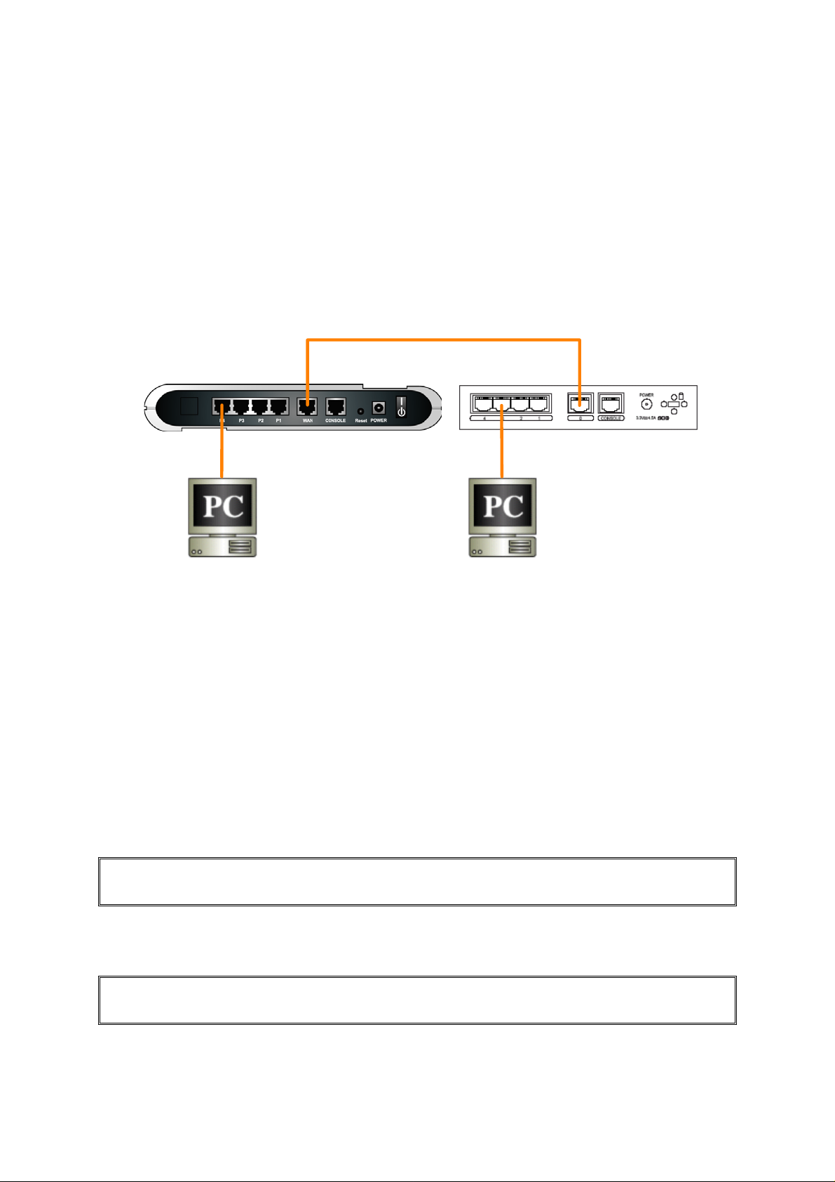
This section describes how to setup the network to carry out the SL1000/SL500 and CISCO PIX 501
Network Configuration as illustrated in Figure 2.1.
Cross Ethernet Cable
WAN:
10.64.2.145
LAN:
10.64.3.1
PC2:
10.64.3.11
Internet Security
Router
Figure 2.1 Network Connections
LAN:
192.168.30.1
WAN:
10.64.2.130
CISCO PIX501
PC1:
192.168.30.2
2.1 Setup Description
PC1 and PC2 are hosts in protected networks running Windows NT/98/2000/XP or Redhat Linux.
Both SL1000/SL500 and PIX Firewall will protect their traffic from external network. NAT is not
required for traffic between the two intranets, which can be transmitted using a VP N tunnel over the
public Internet (in this setup example, a direct connection between two WAN interfaces serves as
public network). However, NAT is required for connections to public Internet.
2.2 Setup CISCO PIX Firewall
2.2.1 Setup IP address of LAN interface
pixfirewall# configure terminal
pixfirewall(config)# ip address inside 192.168.30.1 255.255.255.0
Figure 2.2 Setup LAN port IP address on the PIX firewall
2.2.2 Setup IP address of WAN interface
pixfirewall(config)# interface ethernet0 auto
pixfirewall(config)# ip address outside 10.64.2.130 255.255.255.0
Figure 2.3 Setup WAN port IP address on the PIX firewall
Copyright 2006, ASUSTek Computer, Inc. Page 1
Page 5

2.2.3 Setup Routing Table
pixfirewall(config)# route outside 0.0.0.0 0.0.0.0 10.64.2.145
Figure 2.4 Setup a default route to the PIX firewall
2.3 Setup SL1000/SL500 system
2.3.1 Setup IP address of LAN interface
Figure 2.5 Setup LAN port IP address on the SL1000/SL500
2.3.2 Setup IP address of WAN interface
Figure 2.6 Setup IP address of WAN interface on the SL1000/SL500
Copyright 2006, ASUSTek Computer, Inc. Page 2
Page 6

Figure 2.7 Verify WAN interface configurations on the SL1000/SL500
2.3.3 Setup Routing Table
Figure 2.8 Setup a default route to the SL1000/SL500
3 Establish VPN Tunnel using Automatic Keying
3.1 Configure VPN Policy on PIX 501
Step: 1 Configure access list rule and VPN policy
pixfirewall(config)# access-list SL1000 permit ip 192.168.30.0 255.255.255.0 10.64.3.0 255.255.255.0
pixfirewall(config)# nat (inside) 0 access-list SL1000
pixfirewall(config)# sysopt connection permit-ipsec
pixfirewall(config)# crypto ipsec transform-set set1 esp-3des esp-sha-hmac
pixfirewall(config)# crypto ipsec security-association lifetime seconds 3600
pixfirewall(config)# crypto map toSL1000 20 ipsec-isakmp
pixfirewall(config)# crypto map toSL1000 20 match address SL1000
pixfirewall(config)# crypto map toSL1000 20 set peer 10.64.2.145
pixfirewall(config)# crypto map toSL1000 20 set transform-set set1
pixfirewall(config)# crypto map toSL1000 interface outside
pixfirewall(config)# isakmp enable outside
pixfirewall(config)# isakmp key cwtest address 10.64.2.145 netmask 255.255.255.0
pixfirewall(config)# isakmp identity address
pixfirewall(config)# isakmp policy 20 authentication pre-share
pixfirewall(config)# isakmp policy 20 encryption 3des
pixfirewall(config)# isakmp policy 20 hash sha
pixfirewall(config)# isakmp policy 20 group 2
pixfirewall(config)# isakmp policy 20 lifetime 3600
Copyright 2006, ASUSTek Computer, Inc. Page 3
Page 7

Figure 3.1 Setup VPN policy on the PIX firewall
Step 2: Verify Configurations
pix-firewall# show config
: Saved
: Written by enable_15 at 14:22:39.654 UTC Thu May 4 2006
PIX Version 6.3(4)
interface ethernet0 auto
interface ethernet1 100full
nameif ethernet0 outside security0
nameif ethernet1 inside security100
enable password 8Ry2YjIyt7RRXU24 encrypted
passwd 2KFQnbNIdI.2KYOU encrypted
hostname pix-firewall
domain-name asus.com.tw
fixup protocol dns maximum-length 512
fixup protocol ftp 21
fixup protocol h323 h225 1720
fixup protocol h323 ras 1718-1719
fixup protocol http 80
fixup protocol rsh 514
fixup protocol rtsp 554
fixup protocol sip 5060
fixup protocol sip udp 5060
fixup protocol skinny 2000
fixup protocol smtp 25
fixup protocol sqlnet 1521
fixup protocol tftp 69
names
access-list SL1000 permit ip 192.168.30.0 255.255.255.0 10.64.3.0 255.255.255.0
pager lines 24
mtu outside 1500
mtu inside 1500
ip address outside 10.64.2.130 255.255.255.0
ip address inside 192.168.30.1 255.255.255.0
ip audit info action alarm
ip audit attack action alarm
pdm location 192.168.1.10 255.255.255.255 inside
pdm history enable
arp timeout 14400
global (outside) 1 interface
nat (inside) 0 access-list SL1000
route outside 0.0.0.0 0.0.0.0 10.64.2.145 1
timeout xlate 3:00:00
timeout conn 1:00:00 half-closed 0:10:00 udp 0:02:00 rpc 0:10:00 h225 1:00:00
timeout h323 0:05:00 mgcp 0:05:00 sip 0:30:00 sip_media 0:02:00
timeout uauth 0:05:00 absolute
Copyright 2006, ASUSTek Computer, Inc. Page 4
Page 8

aaa-server TACACS+ protocol tacacs+
aaa-server TACACS+ max-failed-attempts 3
aaa-server TACACS+ deadtime 10
aaa-server RADIUS protocol radius
aaa-server RADIUS max-failed-attempts 3
aaa-server RADIUS deadtime 10
aaa-server LOCAL protocol local
http server enable
http 192.168.1.10 255.255.255.255 inside
no snmp-server location
no snmp-server contact
snmp-server community public
no snmp-server enable traps
floodguard enable
sysopt connection permit-ipsec
crypto ipsec transform-set set1 esp-3des esp-sha-hmac
crypto ipsec security-associat i on lifetime seconds 3600
crypto map toSL1000 20 ipsec-isakmp
crypto map toSL1000 20 match address SL1000
crypto map toSL1000 20 set peer 10.64.2.145
crypto map toSL1000 20 set transform-set set1
crypto map toSL1000 interface outside
isakmp enable outside
isakmp key ******** address 10.64.2.145 netmask 255.255.255.0
isakmp identity address
isakmp policy 20 authentication pre-share
isakmp policy 20 encryption 3des
isakmp policy 20 hash sha
isakmp policy 20 group 2
isakmp policy 20 lifetime 3600
telnet timeout 5
ssh timeout 5
console timeout 0
terminal width 80
Cryptochecksum:8213208c43a8ad0a01202a9686af3ed4
Figure 3.2 Verify VPN configurations on the PIX firewall
Copyright 2006, ASUSTek Computer, Inc. Page 5
Page 9

3.2 Configure VPN Policy on SL1000/SL500
Before configuring VPN, you need to enable VPN service in System Management->System Service
first.
Figure 3.3 Configure VPN policy on the SL1000/SL500
Figure 3.4 Verify VPN configurations on the SL1000/SL500
Copyright 2006, ASUSTek Computer, Inc. Page 6
Page 10

3.3 Verify VPN Tunnel Establishment
pix-firewall# show crypto isakmp sa
Total : 1
Embryonic : 0
dst src state pending created
10.64.2.130 10.64.2.145 QM_IDLE 0 1
pix-firewall# show crypto ipsec sa
interface: outside
Crypto map tag: toSL1000, local addr. 10.64.2.130
local ident (addr/mask/prot/port): (192.168.30.0/255.255.255.0/0/0)
remote ident (addr/mask/prot/port): (10.64.3.0/255.255.255.0/0/0)
current_peer: 10.64.2.145:500
PERMIT, flags={origin_is_acl,}
#pkts encaps: 12, #pkts encrypt: 12, #pkts digest 12
#pkts decaps: 12, #pkts decrypt: 12, #pkts verify 12
#pkts compressed: 0, #pkts decompressed: 0
#pkts not compressed: 0, #pkts compr. failed: 0, #pkts decompress failed: 0
#send errors 0, #recv errors 0
local crypto endpt.: 10.64.2.130, remote crypto endpt.: 10.64.2.145
path mtu 1500, ipsec overhead 56, media mtu 1500
current outbound spi: 5f4579cf
inbound esp sas:
spi: 0x991686ee(2568390382)
transform: esp-3des esp-sha-hmac ,
in use settings ={Tunnel, }
slot: 0, conn id: 1, crypto map: toSL1000
sa timing: remaining key lifetime (k/sec): (74998/3472)
IV size: 8 bytes
replay detection support: Y
inbound ah sas:
inbound pcp sas:
outbound esp sas:
spi: 0x5f4579cf(1598388687)
transform: esp-3des esp-sha-hmac ,
in use settings ={Tunnel, }
slot: 0, conn id: 2, crypto map: toSL1000
Copyright 2006, ASUSTek Computer, Inc. Page 7
Page 11

sa timing: remaining key lifetime (k/sec): (74999/3463)
IV size: 8 bytes
replay detection support: Y
outbound ah sas:
outbound pcp sas:
Figure 3.5 Verify VPN tunnel establishment on the PIX firewall
Figure 3.6 Verify the VPN tunnel establishment on the SL1000/SL500
Copyright 2006, ASUSTek Computer, Inc. Page 8
 Loading...