

Page 1

NOTEBOOK PC
SOFTWARE SETUP & REFERENCE
Product Name: Notebook PC Support CD
Manual Revision: 1.00 E650
Release Date: November 2000
Page 2

Table of Contents
Windows® Quick Install Guide............................................................................................ 3
Support CD for Windows ME & 2000................................................................................. 4
Autorun Screen for Windows ME.................................................................................. 4
Autorun Screen for Windows 2000 ............................................................................... 4
Drivers for Windows ME & 2000 ........................................................................................ 5
VGA Driver ......................................................................................................................... 7
Installing the VGA Driver for Windows ME & 2000 ....................................................... 7
Setting Display Property Settings ................................................................................. 7
Control Panel ..................................................................................................................... 8
Installing the Control Panel for Windows ME & 2000 ................................................... 8
Audio Driver ....................................................................................................................... 9
Installing the Audio Driver for Windows 2000 ............................................................... 9
Audio Controls ............................................................................................................ 10
SpeedStep .......................................................................................................................11
Installing SpeedStep for Windows ME & 2000 ........................................................... 11
ASUS PC Probe............................................................................................................... 12
Installing PC Probe for Windows ME & 2000 ............................................................. 12
TouchPad ......................................................................................................................... 14
Installing the TouchPad Driver for Windows ME......................................................... 14
Installing the TouchPad Driver for Windows 2000 ...................................................... 15
Fast IR Driver ................................................................................................................... 16
Installing the Fast IR Driver for Windows ME & 2000................................................. 16
Configuring the Network Device ................................................................................. 17
LAN Driver........................................................................................................................ 17
Installing the LAN Driver for Windows ME & 2000 ..................................................... 17
Changing Adapter Settings (Windows ME)................................................................. 18
Changing Adapter Settings (Windows 2000).............................................................. 18
Modem Driver...................................................................................................................19
Installing the Modem Driver for Windows ME ............................................................. 19
Installing the Modem Driver for Windows 2000 .......................................................... 20
PC-cillin 2000 ................................................................................................................... 21
Installing the PC-cillin 2000 Anti-Virus Software for Windows ME.............................. 21
Installing the PC-cillin 2000 Anti-Virus Software for Windows 2000 ........................... 25
Hotkey Utility .................................................................................................................... 27
Installing the Hotkey Utility for Windows ME .............................................................. 27
Screen Saver Utility.......................................................................................................... 28
Installing the Screen Saver Utility for Windows ME & 2000 ....................................... 28
Windows ME & 2000 Software Reference...............29
2
Page 3

Windows® Quick Install Guide
1. While the Notebook PC is turned OFF, connect the AiBox to the Notebook PC.
2. Insert the Windows ME/2000 CD into the CD-ROM drive.
3. A T API CD-ROM Drive must be set to boot before the Hard Drive in BIOS setup (press F2 during boot)
or press Esc and select “ATAPI CD-ROM Drive” (use the up and down arrows and press Enter)
4. Press Enter to Setup Windows and press F8 after you have read and accepted the Licensing Agreement.
5. Windows ME: If you have an existing OS, you can choose to install Windows ME in another
directory in order to preserve your existing OS. You will be given an OS choice each time you boot
up your Notebook PC. If you currently use Windows 95/98 and wish to preserve your installed
applications and settings, “upgrade” Windows by installing into your existing directory.
Windows 2000: If you have a previous OS, press ESC to install a fresh copy of Windows 2000.
Follow the next screens to partition your hard drive. Use the “NTFS” file system for increased
functionality.
6. After you install Windows, insert the Notebook PC support CD to install hardware drivers.
3
Page 4
Support CD for Windows ME & 2000
The Notebook PC you purchased may or may not be preloaded with an operating system. The support CD
included with this Notebook PC provides all the necessary drivers and utilities in order for you to use your
Notebook PC with Microsoft® Windows® 95/98/ME/2000/NT4.0 (referred to as “Windows” in this User’s
Manual).
This Notebook PC offers its customers the choice of a pre-installed operating system such as Microsoft
Windows ME (Millennium Edition) or Windows 2000. The choices and languages will depend on the
territory . The levels of hardware and software support may vary depending on the installed operating system.
Operating systems not pre-installed on this Notebook PC may produce different results than the ones described in the provided user’s manuals.
If your Notebook PC is not preloaded with any operating system, or you want to install another operating
system other than the preloaded one, the following pages will give step-by-step installation procedures for
typical system configurations under the Windows
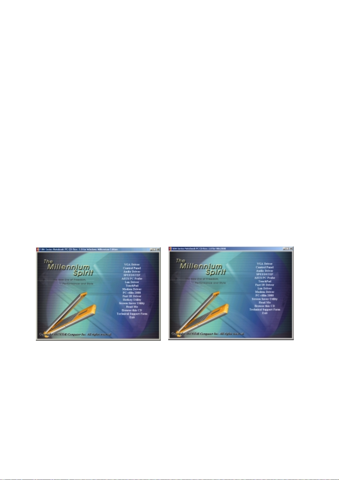
online help provided with each of the applications after installation. The following is what you will see when
you insert the support CD. If the autorun menu does not appear, double clicking the CD-ROM disc drive icon
in “My Computer” (may be the (D:) drive or (E:) drive on hard drives with two partitions) or running
SETUP.EXE (through Start menu “Run...”) located in the root of the support CD, will bring up the autorun
menu.
Autorun Screen for Windows ME Autorun Screen for Windows 2000
®
operating system. For application usage, please see the
4
Page 5

Drivers for Windows ME & 2000
The following are descriptions of what each autorun menu item does when selected with the mouse. Due to
ongoing improvements in the support CD, there may be some differences between this User’s Manual and
your support CD. The names in quotations are the actual driver names displayed in the System Properties of
MS Windows. Windows cannot contain all the device drivers from every manufacturer, with every update;
therefore the provided support CD will contain the best driver for your built-in devices and should be used in
place of any Windows default drivers.
VGA Driver (required)
Installs “Silicon Motion Lynx3DM” display drivers for your operating system in order to properly use the
Notebook PC’s built-in graphics and to provide optimal features. Once the display driver is installed, you can
change your display’s resolution and color through Display Properties. Right click the desktop and choose
Properties or choose Display from the Control Panel. See this section for basic procedures on setting the
display. Read the Windows documentation or W indows help files for detailed information if necessary.
Control Panel (optional)
Installs the Silicon Motion Control Program which is a utility that supports DualView™ and DualApp™
functions as well as other display functions for your Notebook PC.
Audio Driver (required for Windows 2000)
Installs drivers for your operating system in order to properly use the Notebook PC’s built-in audio. The drivers
will enable “ESS Allegro-1.COMM” for high-bandwidth rich audio and “Unimodem Full-Duplex Audio De-
vice” for integration between the audio components and the internal modem. All audio functions are configured
through Windows and help can be located within Windows documentation or Windows help files.
SpeedStep (recommended)
Installs Intel® SpeedStep™. SpeedStep™ is a technology that provides adjustable processor speeds for maximum performance when connected to an external power and battery optimized performance when going
mobile. The processors can dynamically switch clock frequency and voltage, depending on whether the
computer is running on batteries or is plugged into AC power . These changes in frequency happen in only 1/
2000th of a second — so fast, they are invisible to users, even if they occur in the middle of performanceintensive applications.
ASUS PC Probe (optional)
Installs PC Probe utility to monitor the Notebook PC’s CPU temperature and other resources. This is an
optional software to help you better manage your Notebook PC’s resources.
TouchPad (recommended)
Installs Synaptics® TouchPad utility. The Notebook PC fully supports built-in or externally connected keyboard and PS/2 mouse devices. The Notebook PC’s integrated T ouchPad pointing device is fully compatible
with two or three-button PS/2 mice. However, the provided device driver will provide enhancements and
features to the TouchPad to increase the functionality of the TouchPad. For detailed information, see the
Software Reference in the next section. To access help, right-click the TouchPad icon on the taskbar and
select Help.
5
Page 6

Fast IR Driver (required)
Configures your Infrared Transceiver A to “IBM 31T1100” so that your Infrared port can work properly .
LAN Driver (already installed by Windows ME & 2000)
Installs the required LAN driver for the Notebook PC’s built-in 10/100 Fast-Ethernet controller.
Modem Driver
Installs the necessary “HSP56 MR” driver in order for your operating system to have the correct files for the
Notebook PC with built-in modem and “Unimodem Full-Duplex Audio Device” for integration with the
internal audio.
PC-cillin 2000 (optional)
Installs Trend’s PC-cillin 2000, a world-class anti-virus protection software for the new Internet era, to keep
your PC virus-free. This very powerful anti-virus software is bundled with each Notebook PC to protect your
investment. As software become more and more a part of our daily lives, measures have to be taken to
protect them. You may skip this software if you have your own anti-virus software.
Hotkey Utility (optional)
Installs Hotkey utility . Hotkey utility is a program designed to intercept key strokes so that key assignments
can be made to run a program or script. This program cannot be used to change default keys or key combinations used by other software, operating systems, or by the Notebook PC’s hardware. The Hotkey utility is
currently not available for W indows 2000/NT4.0.
Screen Saver Utility (optional)
Installs Screenweaver screen saver utility to provide an amazing Macromedia Flash presentation on the S8
Series Notebook PC features. The Flash file can be found in Program Files \ S8Screen for separate presentation with Flash controls.
Read Me
Gives you notes concerning this support CD or the Notebook PC.
Browse this CD
Shows you the contents of this support CD using W indows Explorer.
Technical Support Form
Opens up a T echnical Support Request Form so that you will understand what kind of information is needed
if you run into problems and require technical assistance.
Exit
Closes the support CD autorun screen.
6
Page 7
VGA Driver
(2000: Item 1, ME: Item 1)
Installing the VGA Driver for Windows ME & 2000
Y our display should appear in full screen but with poor resolution. Just click VGA Driver on the support CD
autorun menu to correct this problem and then restart your Notebook PC. W indows ME will be ready to go
after restart but W indows 2000 requires additional settings. W indows 2000’s display will only use 3/4 of the
screen after restart but appear with a higher resolution. To enlarge the screen to use the entire display , make
changes in the display properties.
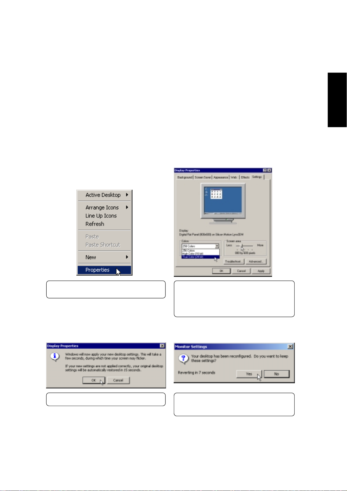
Setting Display Property Settings
VGA Driver
(1) Right-click on the Windows desktop and
click Properties.
(4) Click OK to test your settings.
(2) Click Settings
(3) Set Colors to True Color and Screen area
to 800 by 600 pixels (or 1024 by 768 on
selected models).
NOTE: Setting to larger screen areas will require
panning (by moving your cursor to the screen’s
border) in order to see the entire desktop.
(5) Click Yes to keep your settings. If you click
No or are unable to click to Yes, your previous settings will be restored.
7
Page 8
Control Panel
Installing the Control Panel for Windows ME & 2000
Installation is the same for Windows ME and 2000. Please see Software Reference for more information
on this utility. Insert the support CD and click Control Panel on the autorun menu to start the installation
wizard.
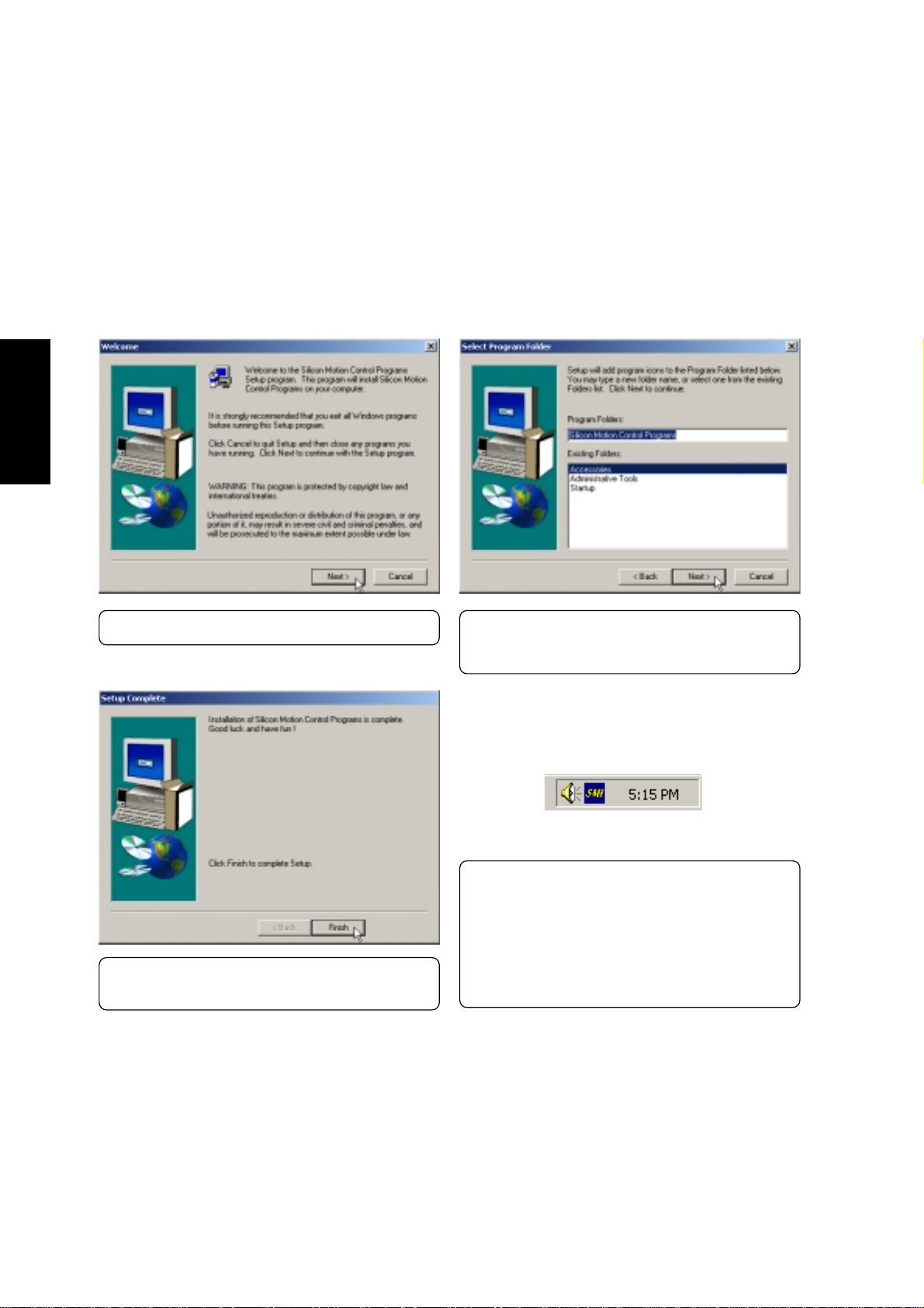
Control Panel
(1) Click Next after reading the “Welcome” screen. (2) Click Next to create program icons in the de-
(2000: Item 2, ME: Item 2)
fault folder or select another folder or type in a
new folder name for the program icons.
(3) Click Finish when you see the “Setup Com-
plete” notice.
8
Windows Task Bar
(4) If you restart Windows, an SMI icon will ap-
pear on the task bar each time Windows starts.
Double-click on the “SMI” icon to view or
change special display settings. Y ou may also
run the Control Program manually through
Start – Programs – Silicon Motion Control
Programs.
Page 9
Audio Driver
(2000: Item 3, ME: Item 3)
Installing the Audio Driver for Windows 2000
Windows ME already has this driver installed. Insert the support CD and click Audio Driver on the
autorun menu to start the installation wizard. Windows 2000 require this driver installation but Windows ME
will have this audio driver installed already. You should run this installation only if you do not hear any
sounds or do not see a speaker icon in the taskbar.
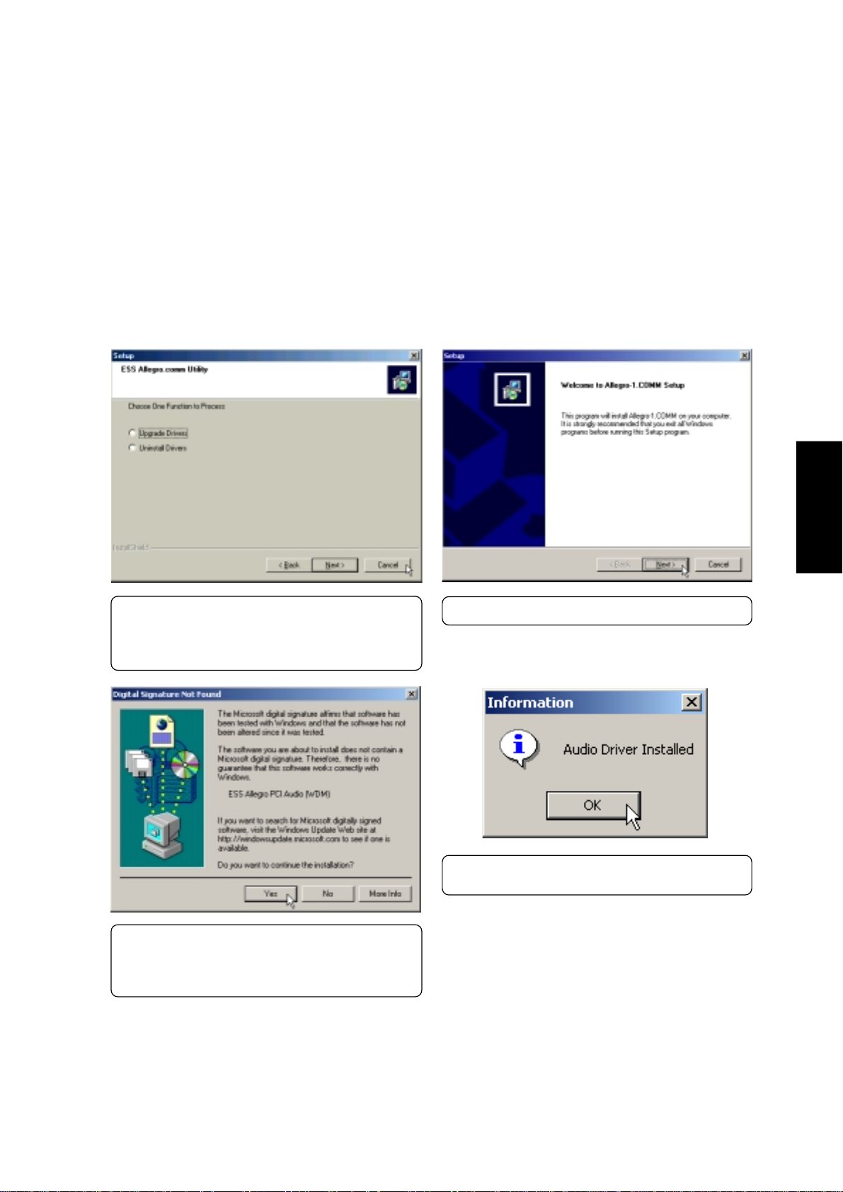
Audio Driver
(*) Since Windows ME already installed the au-
dio driver, you will be asked to upgrade or
uninstall if you run this installation. You can
click Cancel to exit the installation.
(2) Click Yes to accept the driver because the
driver on this support CD has been fully tested
by the Notebook manufacturer to work correctly with MS Windows.
(1) Click Next after reading the “Welcome” screen.
(3) Click OK after the audio driver is installed. Y our
Windows will be restarted automatically.
9
Page 10
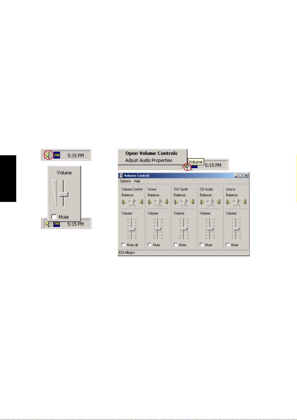
Audio Driver (Cont’)
Audio Controls
A Speaker icon will show on the task bar and when selected with the left mouse button. A simple master
control will show. If selected with the right mouse button a menu will show allowing adjustment of audio
properties or detailed volume controls.
Audio Driver
Mouse Left-Click
Mouse Right-Click
10
Page 11
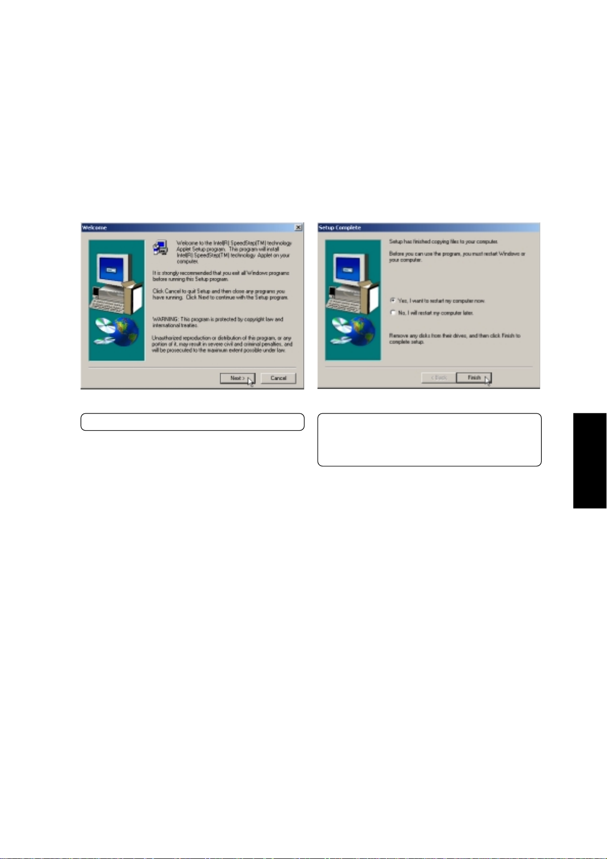
SpeedStep
(2000: Item 4, ME: Item 4)
Installing SpeedStep for Windows ME & 2000
Installation is the same for Windows ME and 2000. Insert the support CD and click SPEEDSTEP on the
autorun menu to start the installation wizard.
(1) Click Next after reading the “Welcome” screen.
(2) Installation has finished. Click “Yes...” and Fin-
ish to restart your computer now or select
“No...” and Finish so that you can install other
items and restart your computer later.
SpeedStep
11
Page 12
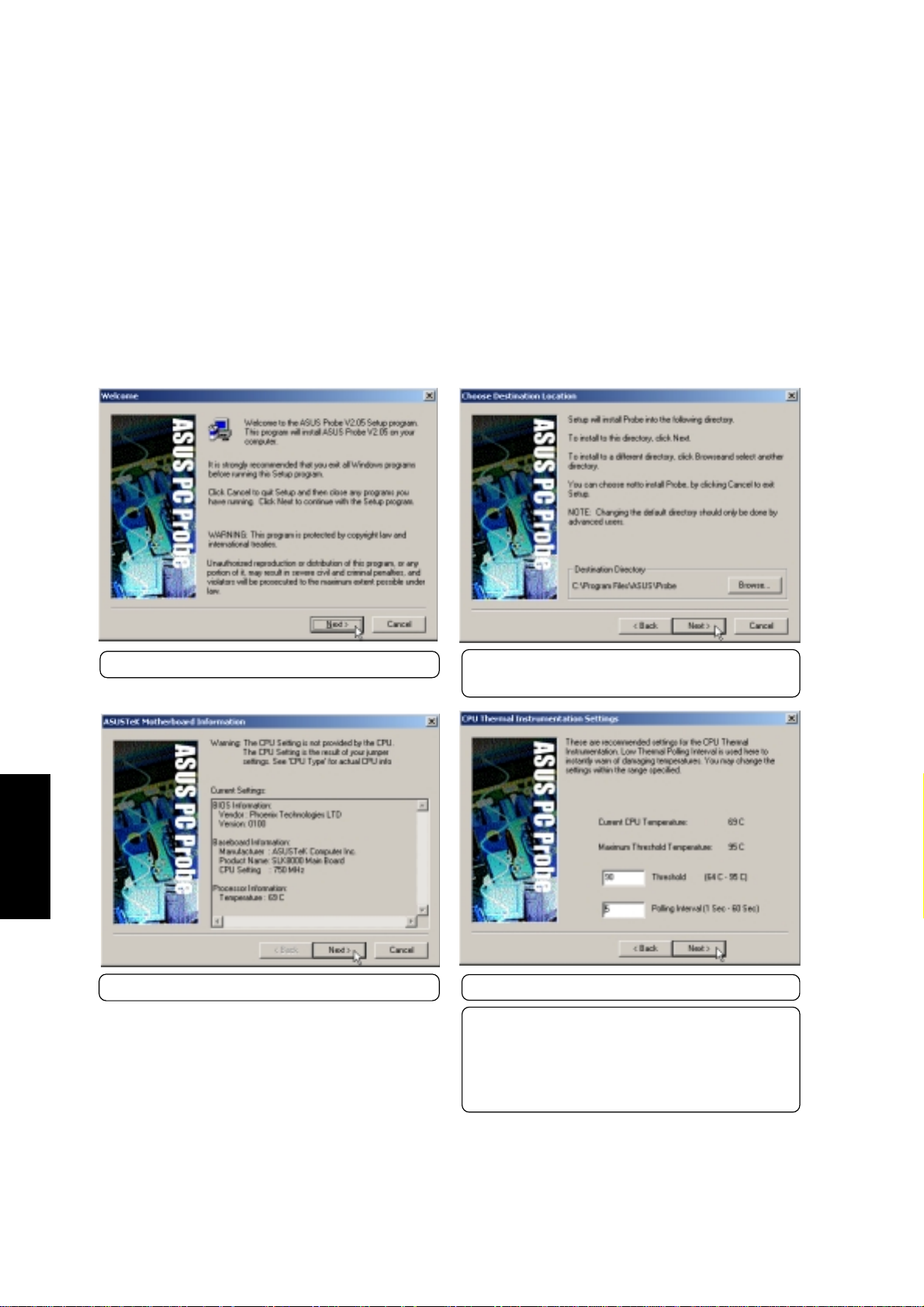
ASUS PC Probe
(2000: Item 5, ME: Item 5)
Installing PC Probe for Windows ME & 2000
Installation is the same for Windows ME and 2000. Insert the support CD and click PC Probe on the autorun
menu to start the installation wizard.
NOTE: In order for PC Probe to run, Intel’s LDCM and other hardware monitoring software
cannot be installed. You must first uninstall other such software before installing PC Probe.
PC Probe
(2) Click Next after reading the Welcome message.
(4) Click Next after reading the current settings.
(3) Browse to another destination folder or click
Next to install to the specified directory.
(5) Adjust the settings if you desire and click Next.
NOTE: You can also make settings any time after you
install PC Probe. The default setting runs a check on
the system every 5 seconds for the Temperature. Decreasing this value increases real-time accuracy but decreases system performance. Increasing this values produce the reverse effect.
12
Page 13
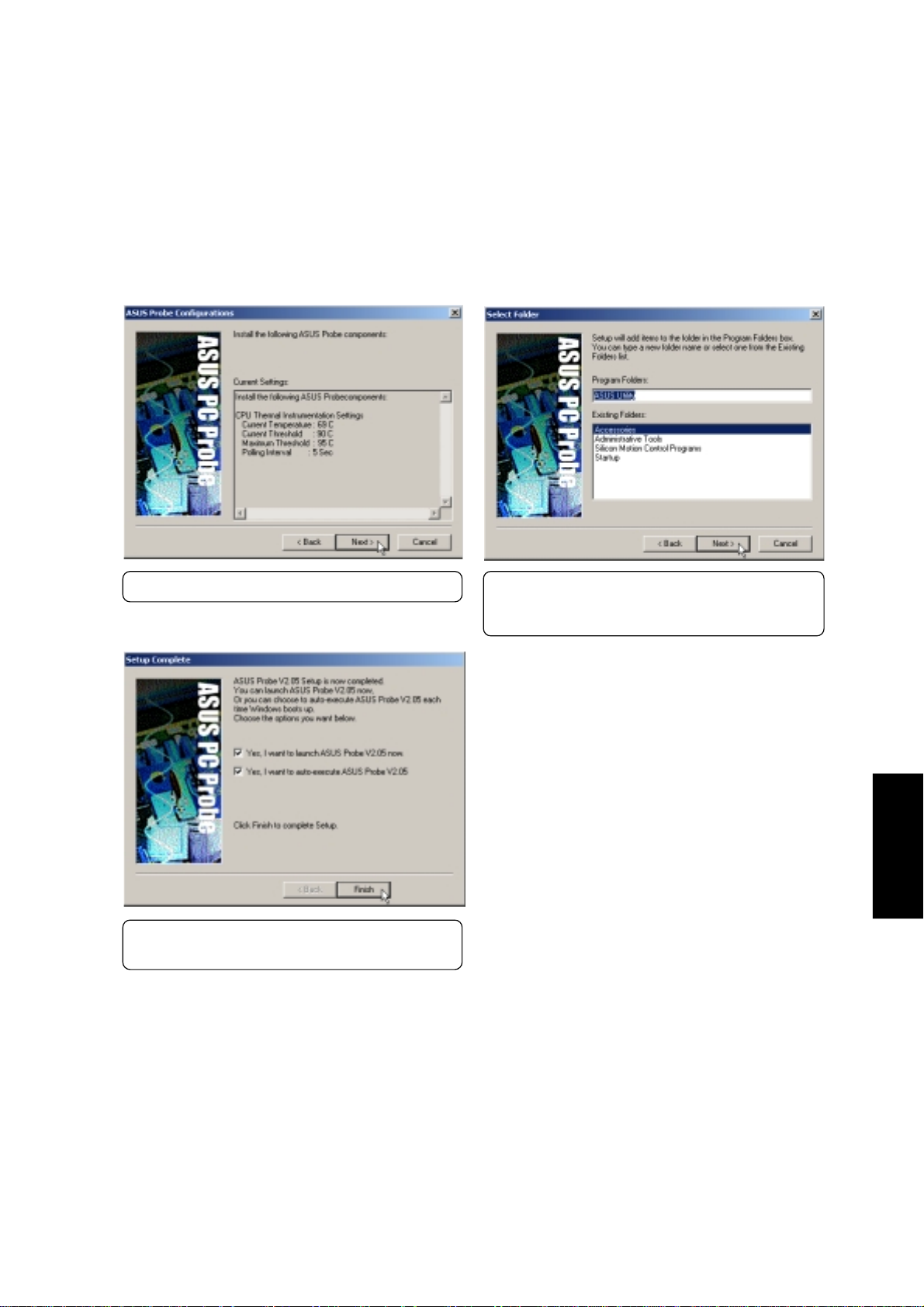
ASUS PC Probe (Cont’)
(6) Click Yes after reading the final settings.
(8) Installation has finished. Click Finish to exit
and execute commands checked above.
(7) Choose another folder, create a new folder,
or click Next to use the default folder for the
program icons.
PC Probe
13
Page 14
TouchPad
(2000: Item 6, ME: Item 7)
Installing the TouchPad Driver for Windows ME
Windows 2000 has different installation steps (see next page). Insert the support CD and click TouchPad on
the autorun menu to start the installation wizard.
PC Probe
(1) Click Next after reading the Welcome message.
(3) Click Next after reading the installation path.
(2) Browse to another destination folder or click
Next to install to the specified directory.
(4) Installation has finished. Select No so that you
can install other items and then click Finish.
14
Page 15
TouchPad (Cont’)
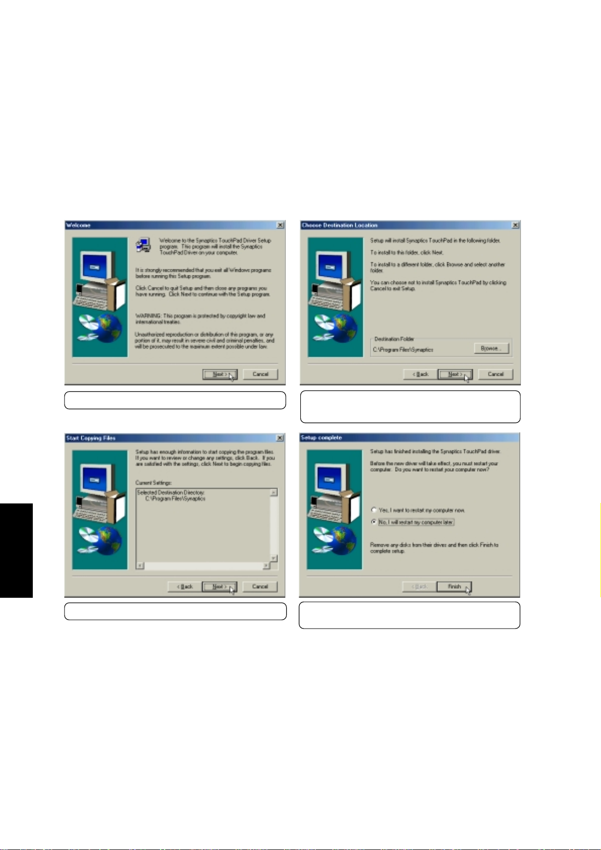
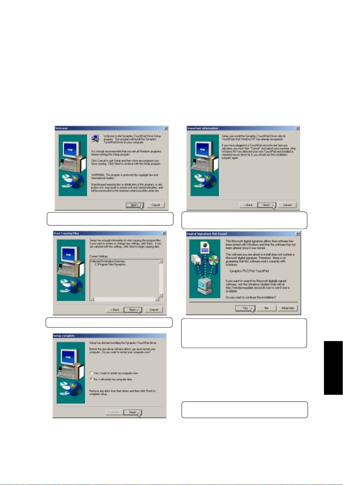
Installing the TouchPad Driver for Windows 2000
Windows ME has different installation steps (see previous page). Insert the support CD and click TouchPad
on the autorun menu to start the installation wizard.
(1) Click Next after reading the Welcome message.
(3) Click Yes after reading the installation path.
(2) Browse to another destination folder or click
Next to install to the specified directory .
(4) Click Yes to accept the driver. The driver on
this support CD has been fully tested by the
Notebook manufacturer to work correctly with
MS Windows.
Touchpad
(5) Installation has finished. Select No so that you
can install other items and then click Finish.
15
Page 16
Fast IR Driver
Fast IR Driver
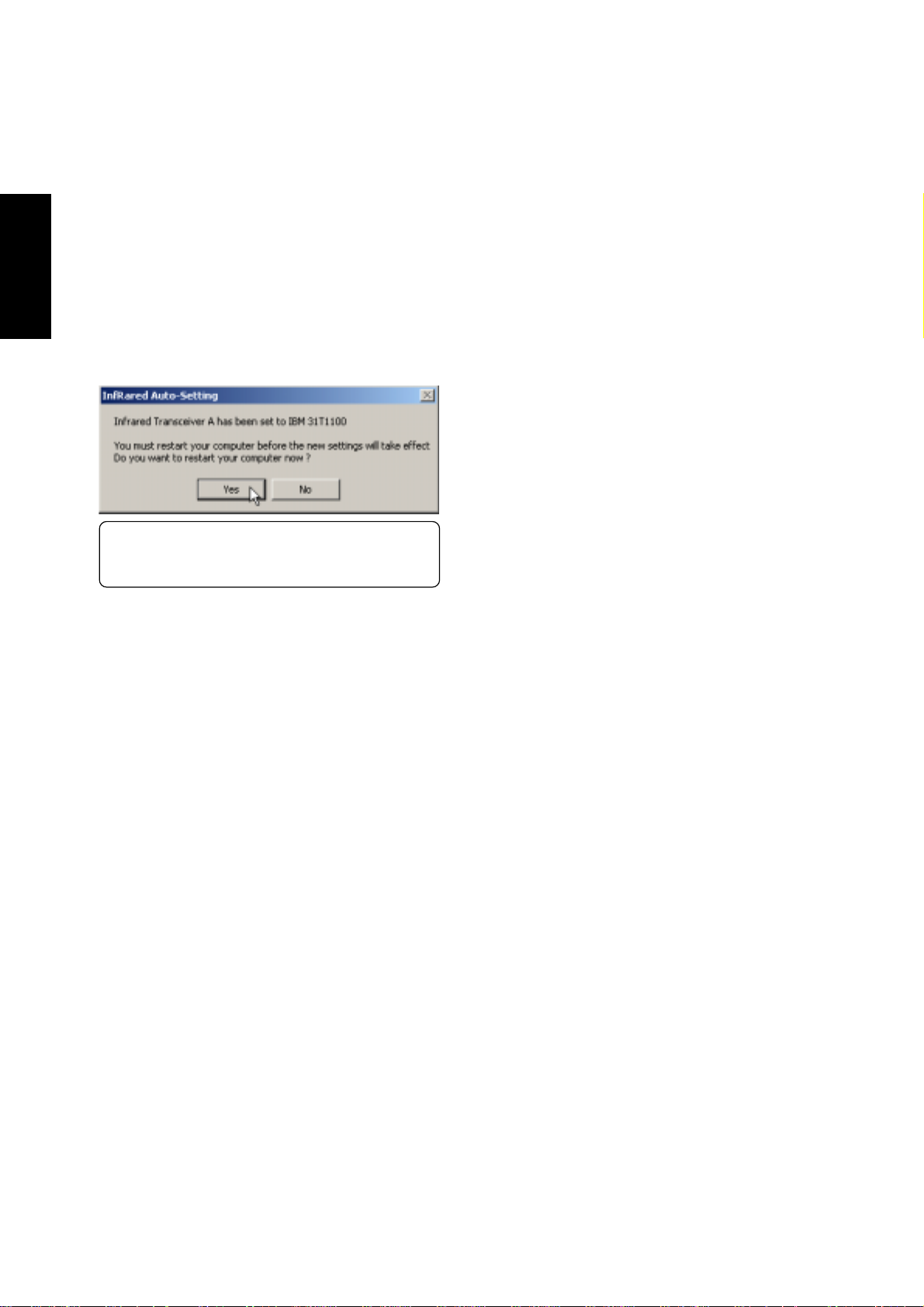
Installing the Fast IR Driver for Windows ME & 2000
Actually W indows has already installed the Fast IR driver but one setting is necessary for this Notebook PC.
Insert the support CD and click Fast IR Driver on the autorun menu to make the setting as shown by the
dialog box.
(1) Click No so that you can install other drivers.
(2000: Item 7, ME: Item 10)
Clicking Y es will automatically restart your computer.
16
Page 17
LAN Driver
(2000: Item 8, ME: Item 6)
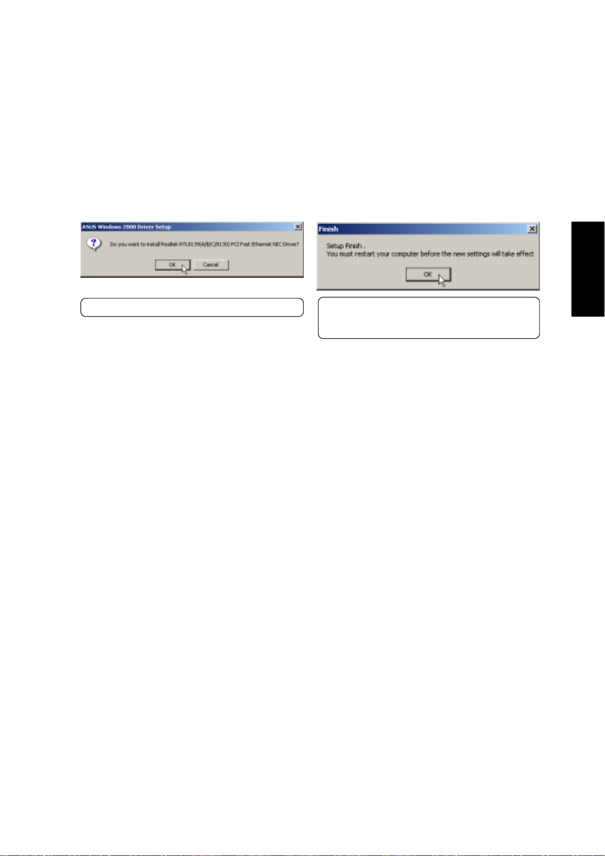
Installing the LAN Driver for Windows ME & 2000
The LAN driver should already be installed by W indows 2000 & ME. If you have troubles making network
connections contact your network administrator. If you need to reinstall, insert the support CD and click Lan
Driver on the autorun menu to start the installation wizard.
(1) Click OK to begin installing drivers.
Configuring the Network Device
(2) Installation has finished. Click OK to restart
your computer. Y our computer will automati-
cally restart.
LAN Driver
The network device has the ability to send and receive packets at the same time (full-duplexing) at both 10
and 100 Mbps. In order to reap the benefits of full duplexing, you MUST have a full duplex hub or switch.
The network device has the added ability to “talk” to the hub or switch and determine at which mode to
communicate (either full or half duplex). This is called auto-negotiation. You must have an auto-negotiating
hub or switch to get full duplex support with the Duplex Mode set to Auto. If you don’t have an auto-
negotiating hub or switch and want to run at full duplex, set Duplex Mode to Full and then set the SPEED
parameter to either 100 Mbps or 10 Mbps.
(See next page for examples.)
17
Page 18
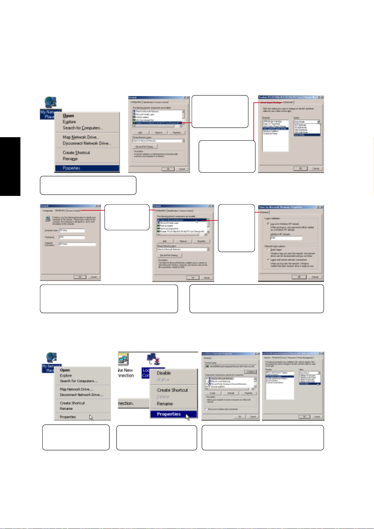
Changing Adapter Settings (Windows ME)
Double click on the
Realtek driver to
make network controller settings.
LAN Driver
Right-click the Network icon on
the desktop and select Properties.
Use the tabs
for other network settings.
Identification is necessary to use the network browser.
Enter a workgroup as instructed by your network administrator or try using your domain name.
You can make settings such as 10 or
100 mode on the
Advanced page.
Double
click on the
Network
driver to
make logon
settings.
If you want to log into a server, you must check
“Log on...” and enter your domain name. Windows
95/98/ME/2000 all use Windows NT domain.
Changing Adapter Settings (Windows 2000)
Right-click the Network
icon on the desktop and
select Properties.
Right click the network connection and select Properties.
18
Click Configure to make network driver settings. Double-click the individual drivers to
make network settings.
Page 19
Modem Driver
(2000: Item 9, ME: Item 8)
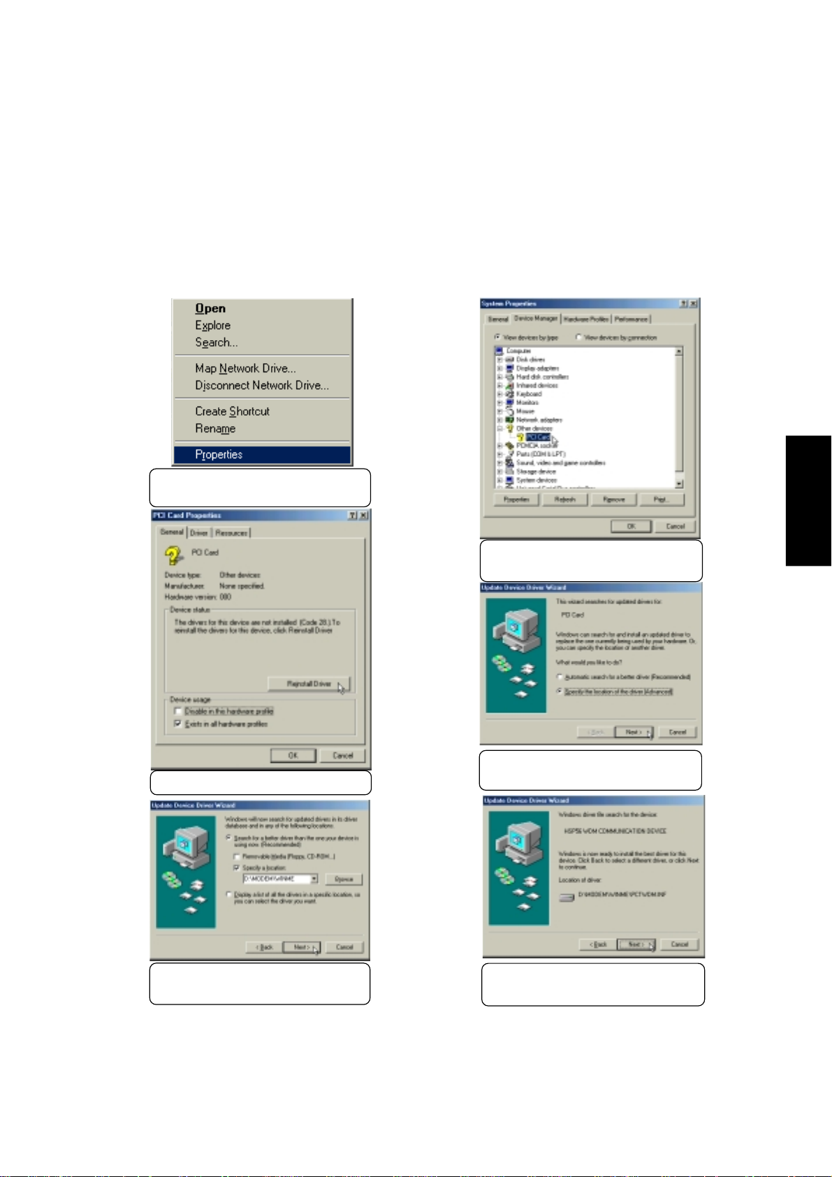
Installing the Modem Driver for Windows ME
Installation is different for W indows ME and 2000. Find the Windows 2000 steps after W indows ME.
Insert the support CD and follow the steps below to install the modem driver. There is no installation wizard
for this process.
(1) Right-click “My Computer” and
select Properties.
(3) Click Reinstall Driver.
(2) Double-click PCI Card to see its
properties.
(4) Select “Specify the location...”
and click Next.
Modem Driver
(5) Enter the path “\modem\winme”
and click Next.
(6) Click Next when the driver is lo-
cated by Windows.
19
Page 20
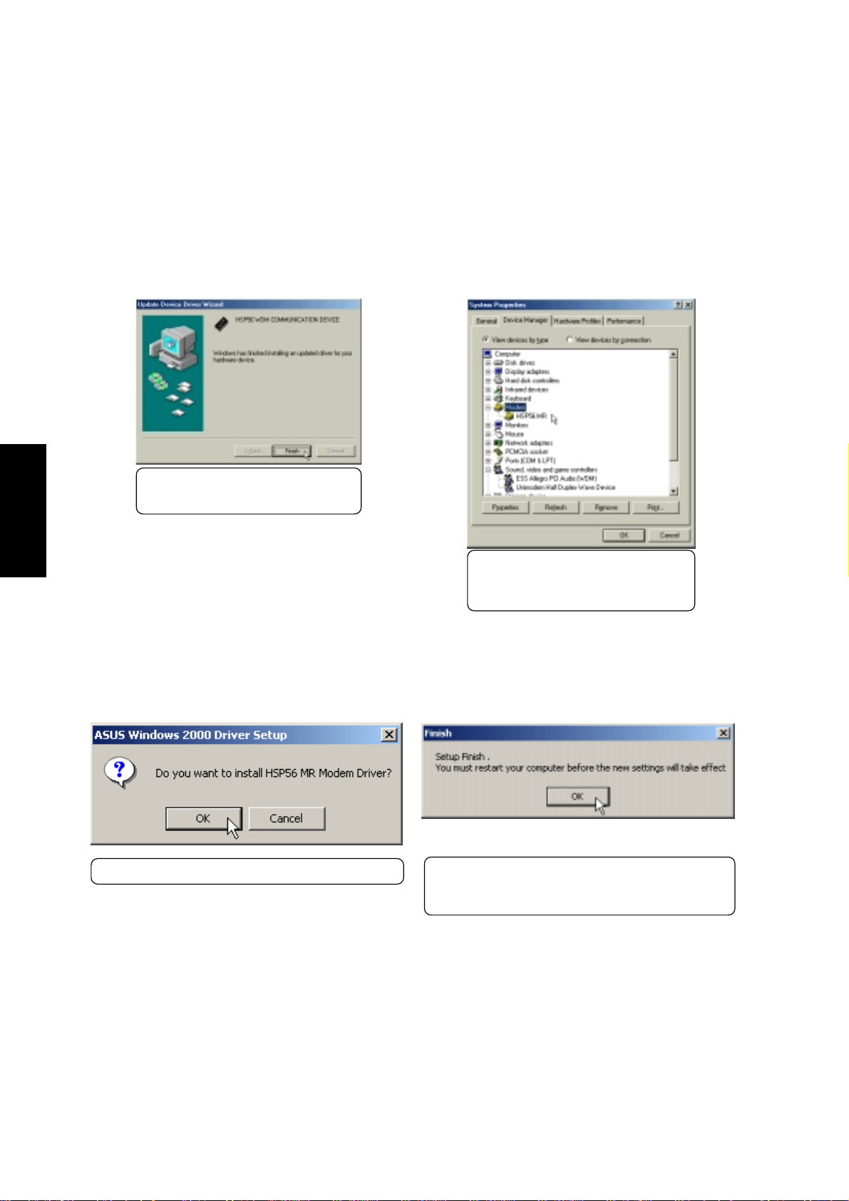
Installing the Modem Driver for Windows ME (Cont’)
Modem Driver
(7) Click Finish after Windows fin-
ishes installing the driver.
(*) You should now see “HSP56 MR”
under Modem and “Unimodem
Half Duplex Wave Device”
Installing the Modem Driver for Windows 2000
Installation is different for Windows ME and 2000. Find the Windows ME steps before Windows
2000. Insert the support CD and click Modem Driver on the autorun menu to start the installation wizard.
(1) Click OK to begin installing drivers.
(2) Installation has finished. Click OK to restart
your computer. Y our computer will automati-
cally restart.
20
Page 21
PC-cillin 2000
(2000: Item 10, ME: Item 9)
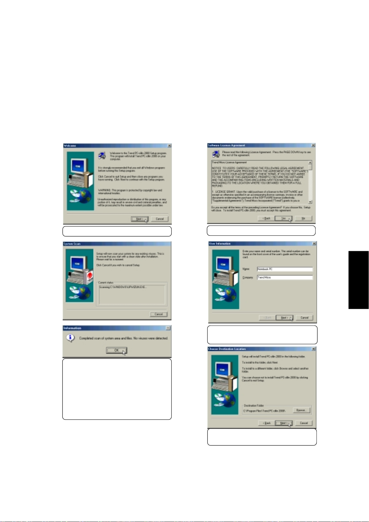
Installing the PC-cillin 2000 Anti-Virus Software for Windows ME
Installation is different for W indows ME and 2000. The following are steps for Windows ME. Insert the
support CD and click PC-cillin 2000 on the autorun menu to start the installation wizard.
(1) Click Next to begin the installation wizard.
(3) Wait while your setup checks your
system for viruses based on the included pattern file. (This is usually
older than what is available on the
Internet at “http://www.trend.com”.
Y ou should rescan your hard drives
after updating the virus pattern.) The
OK when completed.
(2) Click Y es after reading the “Agreement”.
PC-cillin 2000
(4) Enter your “Name” and “Company”
(if relevant) and click Next.
(5) Choose another destination folder or
click Next to use the default.
21
Page 22
Installing the PC-cillin 2000 for Windows ME (Cont’)
PC-cillin 2000
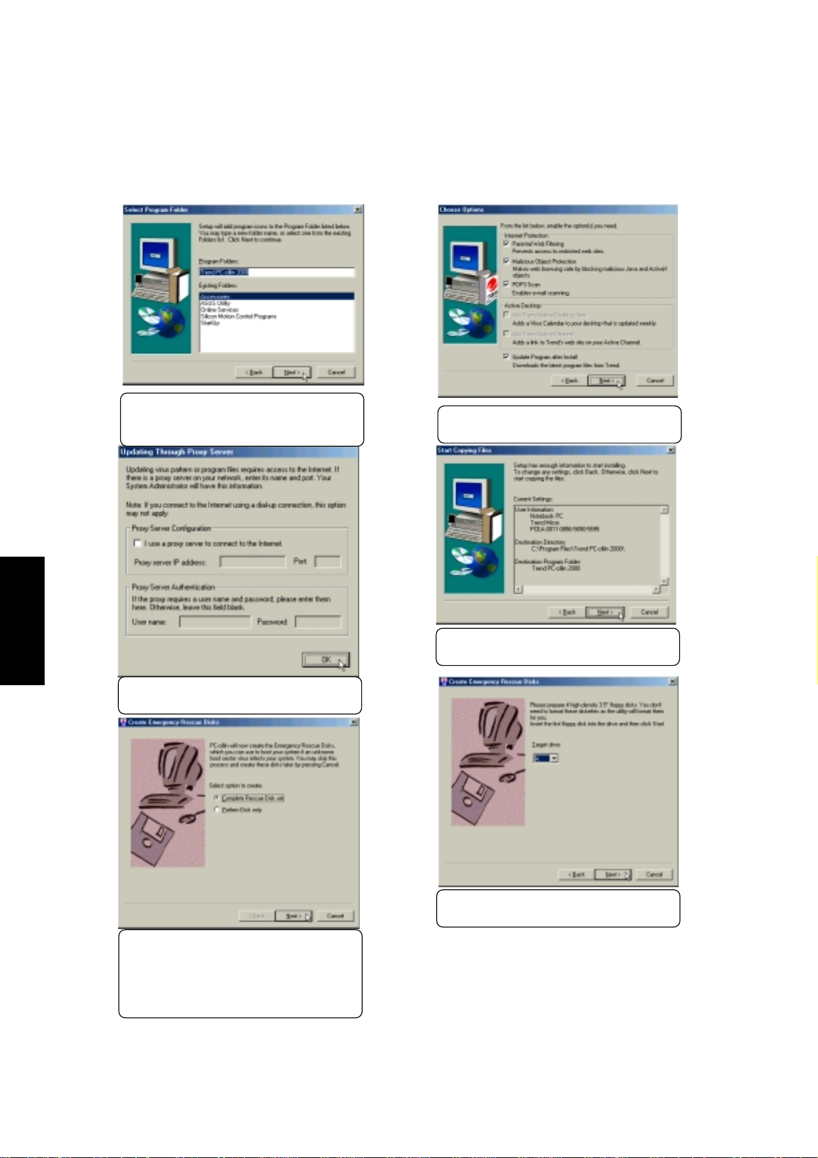
(6) Choose another folder, create a new
folder, or click Next to use the default
folder for the program icons.
(8) Make proxy settings if necessary and
click OK to continue.
(7) Make Internet and Desktop settings
and click Next to continue.
(9) Check the installation settings and
click Next to continue.
22
(11)Select a target floppy disk drive and
click Next.
(10)Y ou will be asked to create either com-
plete rescue disks or virus pattern
disk. Select one and click Next. You
must have a USB floppy disk drive to
create rescue diskettes.
Page 23
Installing the PC-cillin 2000 for Windows ME (Cont’)
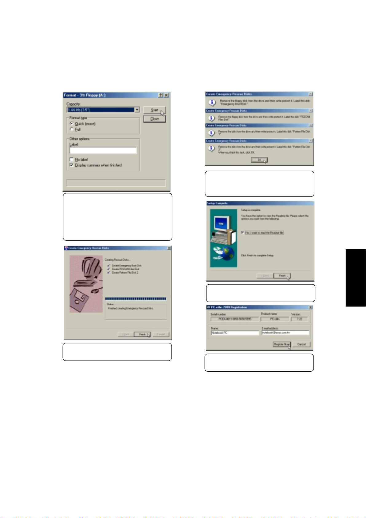
(13)You will be asked to repeat this step
four times if you chose the “Complete
Rescue Disk Set”.
(12)You will be asked to format your
floppy disk. Use Quick (or Full if necessary) and click Start. Click Close
when format is completed. If you
chose the full rescue disks, you have
to repeat this step four times.
(14)Click Finish when the “Rescue Disks”
are created.
(15)Click Finish when the setup is com-
plete.
(16)Enter your “Name” and “Email Ad-
dress” to register PC-cillin software.
PC-cillin 2000
23
Page 24
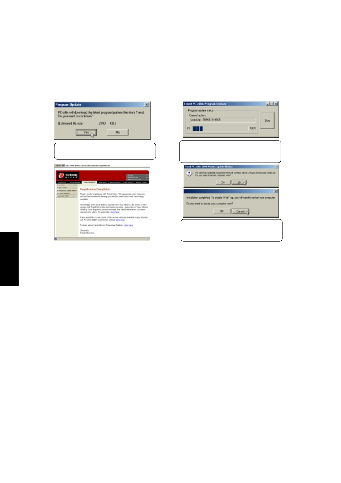
Installing the PC-cillin 2000 for Windows ME (Cont’)
PC-cillin 2000
(17)Click Y es to update PC-cillin’s pro-
gram and virus pattern files.
(18)Be patient while your computer con-
nects to the Internet and download
necessary files.
(19)You can answer No and Cancel so
that you can install other drivers then
restart your computer later.
24
Page 25

Installing the PC-cillin 2000 Anti-Virus Software for Windows 2000
Installation is different for Windows ME and 2000. The following are steps for Windows 2000. Insert
the support CD and click PC-cillin 2000 on the autorun menu to start the installation wizard.
(1) Click Next after reading the Welcome mes-
sage.
(3) Wait while your setup checks your system for
viruses based on the included pattern file.
(This is usually older than what is available
on the Internet at “http://www.trend.com”. You
should rescan your hard drives after updating the virus pattern.) This screen will change
when completed.
(2) Click Next after reading the license agreement.
PC-cillin 2000
(4) Enter your “User Name” and “Organization” if
applicable. Click Next to continue.
25
Page 26

Installing PC-cillin 2000 for Windows 2000 (Cont’)
(5) Change the destination folder or click Next to
PC-cillin 2000
(7) Installation has finished. Select Finish to exit
install to the specified directory.
the installation wizard. No restart is necessary .
(6) Click Install now or click Back to make
changes to the installation settings.
(*) An icon will be placed in your taskbar to show
protection status and allow quick access to the
PC-cillin software settings.
26
(*) Right-click the icon for quick software settings.
Page 27

Hotkey Utility
(2000: None, ME: Item 11)
Installing the Hotkey Utility for Windows ME
Installation is not currently available for W indows 2000. Insert the support CD and click Hotkey Utility
on the autorun menu to start the installation wizard.
(1) Click Next on the “Welcome” screen.
(3) Choose another folder, create a new folder , or
click Next to use the default folder for the program icons.
(2) Choose another destination folder or click Next
to use the default.
Hotkey Utility
(4) Click Finish to exit the installation wizard and
execute the selections. You can deselect the
check boxes before clicking Finish if you want.
27
Page 28

Screen Saver
Screen Saver Utility
Installing the Screen Saver Utility for Windows ME & 2000
Installation is the same for Windows ME and 2000. Insert the support CD and click Scr een Saver Utility
on the autorun menu to start the installation wizard.
(2000: Item 11, ME: Item 12)
(2) Click Yes to create the installation folder. The
screen saver will install and run immediately .
(1) Enter a different installation path or click
Install to use the specified path.
28
Page 29

NOTEBOOK PC
SOFTWARE REFERENCE
WINDOWS ME & 2000
Page 30

Contents
NOTEBOOK PC 29
VGA DRIVER 33
Dual Display Settings (Windows ME and 2000) ......................................................... 34
Enabling an External Monitor...................................................................................... 34
Display Arrangement................................................................................................... 36
Color Setting Note....................................................................................................... 36
SPEEDSTEP 37
®
Intel
SpeedStep™ Overview .......................................................................................... 38
How it Works ....................................................................................................................38
IT Friendly ........................................................................................................................ 39
Summary.......................................................................................................................... 39
SpeedStep Properties and Settings................................................................................. 40
SpeedStep Software Notes.............................................................................................. 42
ASUS PC PROBE 43
ASUS PC Probe............................................................................................................... 44
Starting ASUS PC Probe.................................................................................................. 44
Using ASUS PC Probe Monitoring ................................................................................... 45
ASUS PC Probe Task Bar Icon ................................................................................... 46
TOUCHPAD 47
Overview of Synaptics
®
TouchPad Features .................................................................... 48
Tap on the Pad Instead of Pressing the Buttons......................................................... 48
Drag Icons, Windows and Other Objects without Using Buttons ................................ 48
Adjust the Overall Touch Sensitivity ............................................................................ 49
Customize Buttons and Taps ...................................................................................... 49
Prevent Accidental Pointing While Typing................................................................... 50
Scroll Through A Document without Using Scroll Bars ............................................... 50
Zoom In/Out and Pan on Documents ......................................................................... 50
Move the Pointer Long Distances ............................................................................... 51
Fine Tune the Pointer Movement................................................................................ 51
Accessories................................................................................................................. 51
More About the TouchPad........................................................................................... 51
Page 31

Property Pages ................................................................................................................ 51
Scrolling Properties Page ........................................................................................... 52
Button Actions and Tap Zones Properties Pages........................................................ 53
More Features Properties Page.................................................................................. 54
Button Actions Properties Page ..................................................................................55
Touch Properties Page................................................................................................ 56
Edge Motion Properties Page .....................................................................................57
Frequently Asked Questions ............................................................................................ 58
PC-CILLIN 2000 61
Welcome to PC-cillin ........................................................................................................ 62
HOTKEY UTILITY 67
ASUS Hotkey ................................................................................................................... 68
Buttons........................................................................................................................ 68
Hotkey Actions ............................................................................................................ 69
Add “Run Program” Procedure ................................................................................... 72
APPENDIX 73
Using New Hard Disk Drives............................................................................................ 74
Creating a Bootable Diskette ...................................................................................... 74
Using the FDISK.EXE Utility ....................................................................................... 74
Formatting the Hard Disk Drive................................................................................... 74
Using Save-to-Disk (Windows 95/98) .............................................................................. 75
Creating a Save-to-Disk Partition................................................................................ 75
Creating a Save-to-Disk File .......................................................................................75
Updating Your BIOS .........................................................................................................76
Creating a BIOS Update Floppy Disk ......................................................................... 76
Copying BIOS Update Files to the Hard Disk Drive.................................................... 76
Updating BIOS with a Floppy Disk Drive .................................................................... 77
Updating BIOS From the Hard Disk Drive .................................................................. 77
Modem Communication Regulations ............................................................................... 78
FCC Regulations......................................................................................................... 78
FCC Part 68 Requirements......................................................................................... 78
Modem Declaration Of Conformity.............................................................................. 79
Canadian Department Of Communications (CDOC): ................................................. 79
Page 32

Page 33

VGA DRIVER
Topics Covered:
Dual Display Settings
Display Arrangement
Enabling an External Monitor
Color Settings
Windows ME & 2000
Page 34

VGA Driver
Dual Display Settings (Windows ME and 2000)
When you enter the Display Properties Settings, two displays will be shown which allow you set the resolution, color, and monitor type independently from each other in order to make independent display adjustments. Dual display provides the following two features:
• Dual Application – Display independent applications (graphics or video) on two different displays.
• Dual View – Display a selectable rectangular portion of the primary display full screen on a second-
Lynx3DM Settings
Such as a spreadsheet on one display and a presentation on another display.
ary display while keeping the first display in normal view.
(1) Right click the
desktop and select
Properties.
(2) Click the Settings tab.
(3) Click the Advanced button in
the Display Properties Settings
and Click the Lynx3DM tab
Enabling an External Monitor
Use the LCD/Monitor Function keys <Fn><F8> to toggle between the Notebook PC’s
LCD display and an external monitor in this series: Notebook PC LCD -> External Monitor -> Both. You can also enable or disable displays using the display settings software.
NOTE: Once DualView or
NOTE: DualV iew and DualApp
cannot run at the same time and
both require setting “Colors” to
High Color (16 bit).
DualApp is activated, your
screen area will be set to 1600
by 600 and your cursor can move
past your visible screen area.
Fn
F8
LCO
34
Page 35

When you turn ON DualView , you will be given
a few options. You may have to experiment a
few times to make the best use of this software.
Lynx3DM Settings (Windows 2000)
VGA Driver
If you wish to use hot keys to activate special
display functions, make them here. Defaults will
be displayed here for your convenience. Y ou will
have to check “Enable Hot Key” on the
L ynx3DM (previous screen) in order to activate
this function.
The Lynx3DM settings tab in Windows 2000 is
the same as in Windows ME but will include a
disabled “Stretch” function. The software stretch
function is not required for this Notebook PC.
35
Page 36

VGA Driver
When you choose the second monitor, you will be asked whether you want to activate the second monitor.
Select Y es to enable the second monitor. You can uncheck (first select the second monitor) the “Extend my
Windows desktop onto this monitor” at any time to disable the second monitor on the Notebook PC.
NOTE: Making dual display settings do not require a second display to be connected, but using
either Dual Application or Dual View requir es a second display to be connected to the VGA port
on the Notebook PC.
Display Arrangement
You can drag either display with your cursor in order to arrange
the two displays in a configuration that is convenient for your use.
In this example, the second display can be accessed by moving
down from the first display .
The VGA output to the second monitor connected to this Notebook PC can only use up to 800 by 600 pixels with True Color.
Using screen areas greater than this will fail to display anything.
Click OK if you can see this dialog box. If you don’t pay attention, your settings will be reverted back to your previous settings.
Color Setting Note
Y ou can ignore this warning on this Notebook PC and select “Apply the new color settings without restarting” and “Don’t ask this
question again” so that you don’t have to restart your computer
each time you make a color setting.
36
Page 37

Topics Covered:
SPEEDSTEP
Intel
How it Works
IT Friendly
Summary
SpeedStep Properties and Settings
SpeedStep Software Notes
®
SpeedStep™ Overview
Windows ME & 2000
Page 38

Intel® SpeedStep™ Overview
Most important, the new processors, rated at frequencies of 600MHz and above, will be the first to incorporate an innovative performance technology called Intel® SpeedStep™ technology . Built into certain mobile
Pentium III processors, this technology from Intel provides near-desktop performance with all the benefits
of mobility . When connected to an AC power source, mobile Pentium III processors featuring Intel SpeedStep
technology will deliver near-desktop-level performance. When working on battery , the mobile PC automati-
SpeedStep
cally detects the change and drops both the processor clock frequency and voltage to deliver outstanding
performance without compromising battery life. This new technology will be available in the thinnest and
lightest mobile PCs, so users won’t have to compromise in order to enjoy the mobility they have come to
expect.
How it Works
Mobile Pentium III processors featuring Intel SpeedStep technology can be switched between two performance modes—maximum performance and battery-optimized performance—either automatically or by
user command. By default, mobile PCs with mobile Pentium III processors featuring Intel SpeedStep technology detect when they are plugged into or unplugged from an AC outlet. When a system is unplugged, the
processor core automatically drops to a battery optimization2 level from the peak frequency1. At the same
time, the operating voltage of the processor drops to 1.35 volts from 1.6 volts. Plug that system back into an
outlet, and the processor automatically speeds back up to peak frequency1 and boosts voltage to 1.6 volts.
Users can also manually adjust the Intel SpeedStep technology mode. For example, if a user needs to conduct a presentation away from an outlet, he or she can use the Intel SpeedStep technology applet to put the
mobile PC into maximum performance mode. The applet is accessed via an icon in the W indows* Taskbar .
When the presentation is complete, the system can be put back into battery-optimized performance mode.
When switching performance modes, Intel SpeedStep technology can reduce the active power of the processor up to 45% while maintaining up to 80% of the maximum performance. Switching voltage levels provides
significant power savings, because power consumption occurs in proportion to the square of voltage. By
contrast, clock frequency has a linear relationship with power consumption. The result: A slight reduction in
voltage yields a significant impact on power savings. Of course, the overall impact on battery life depends on
the application running and the design and components of the mobile PC.
1
Peak Frequency
• 600&650MHz • 500MHz
• 700MHz • 550MHz
• 750MHz • 600MHz
• 800MHz • 650MHz
• 850MHz • 700MHz
2
Battery Optimization
38
Page 39

IT Friendly
IT managers will be glad to know that Intel SpeedStep technology functionality is completely seamless. If
we look under the hood, we find that Intel SpeedStep technology uses Intel® QuickStart technology to put the
processor into “sleep” mode. The voltage level and processor frequency are then adjusted and the system
awakened. The process is completely transparent to running applications and takes just one-half of a millisecond to complete—less time than the blink of an eye.
What’s more, IT managers won’t have to worry about implementing Intel SpeedStep technology in the
enterprise. The technology works with all major operating systems, including Microsoft’s Windows 95/98/
ME and Windows NT 4.0/2000.
Summary
When the notebook is plugged in, mobile Pentium III processors run at peak clock frequency. When the
system runs on battery power, clock rates drop to a battery optimization level.
• Operating voltages also switch, dropping to 1.35 volts when unplugged from 1.6 volts when running
off an AC power source.
• The mode switch can be invoked automatically when systems are plugged into or unplugged from an
outlet, or by user command using a simple utility.
• Mode switches occur in less than one-half a millisecond and are completely transparent to both the
end user and running applications.
• Intel mobile Pentium III processors featuring Intel SpeedStep technology allow OEMs to build mobile PCs that closely match the performance and capabilities of advanced desktop systems.
SpeedStep
39
Page 40

SpeedStep Properties and Settings
SpeedStep
NOTE: If your processor does not support
SpeedStep, the blue flag will have an “x” over it.
Entering the properties page (double clicking with
left button or selecting the menu called up by the
right button) will show grayed out items.
Passing the cursor over the blue flag icon will
show the performance status. There are two statuses: “Maximum Performance” or “Battery
Optimized Performance”.
40
Select “Ask me before automatically
changing performance” if you tend to
plug and unplug the power while the
Notebook PC is running applications.
This will ensure that running applications do not stop due to a decrease in
processor speed.
Page 41

SpeedStep Properties and Settings (Cont’)
SpeedStep
Y ou can independently choose the performance level
while “running on batteries” and when “plugged in”.
You may have to restart your computer in order to
activate certain settings.
Right-clicking the blue flag will give you a
menu in order to manually change the processor speed and to enter the properties page.
Clicking “Advanced” gives you the choice to:
Disable SpeedStep - Your Notebook PC will always
run at the maximum processor speed regardless of
whether an AC power source is present.
Remove icon from taskbar - Removes the blue flag
icon from the taskbar . You will then have to enter the
properties settings through the Control Panel “Power
Management” icon.
Disable audio notification when performance
changes - By default, a “ping” sound is heard when
speed changes. If the noise is a problem, you can disable it here.
41
Page 42

SpeedStep Software Notes
WARNING
You are authorized and licensed to install this application and driver ONLY on a Licensed PC that has
System Management Mode (SMM) BIOS support installed. This driver may permanently damage any
system that does not meet these requirements. A Licensed PC is a computer which (1) is capable of seamlessly and automatically transitioning among multiple performance states (potentially operating at different
SpeedStep
efficiency ratings) based upon power source changes, end user preference, processor performance demand,
and thermal conditions; and (2.) includes an Intel mobile Pentium II processor, Intel mobile Pentium III
processor, or any other future Intel processors that incorporates the capability to transition between dif ferent
performance states by altering some or any combination of the following processor attributes: core voltage,
core frequency, bus frequency, number of processor cores available, or any other attribute that changes the
efficiency (instructions/unit time-power) at which the processor operates.
The User Interface
The User Interface is accessed either from the system tray icon (a “flag”) or from the power management
icon in the Control Panel. If the user does not have restricted privileges (on Windows 2000 or NT4.0), the
User Interface allows the user to select their processor performance level preference for when the computer
is running on AC or on battery . The User Interface allows for advanced options, such as disabling the Applet.
Disabling the Applet only disables the user’s ability to set preferences and control transitions, it does not
disable Intel SpeedStep technology in the BIOS. The Applet never issues a SetSpeedStepSetup SMI command with ECX = 0xFF to disable control. The only way to completely disable Intel SpeedStep technology
is via the BIOS setup.
Restricted User limitations
With some Windows operating systems, like W indows 2000, a user account can be created that has restricted
access to the operating system and its environment. While the IST Applet will run correctly, the system
preferences will not be available for the user to modify. System level preferences include the ability to
disable the Applet and the ability to set processor performance level preferences for AC and battery. These
choices will be grayed out. User preferences will not be effected.
Over-installing
If the Intel SpeedStep technology Applet has been installed previously, we recommend that you first uninstall the Applet.
If you over-install the Intel SpeedStep technology Applet without first uninstalling, the Applet must be
removed from the running task list. If the Applet is running while attempting to over-install, an error message will appear informing the user to first uninstall the Applet before proceeding. Also, the OEM configuration and user preference values stored in the Windows registry will be overwritten by the values contained
in the Registry .ini file that is part of the installation package.
Uninstalling the Applet
Open Contr ol Panel – Add Remove Programs and select the Intel SpeedStep technology Applet entry and
press Add/Remove.
42
Page 43

ASUS PC PROBE
Topics Covered:
Starting ASUS PC Probe
Using PC Probe Monitoring
ASUS PC Probe Task Bar Icon
Windows ME & 2000
Page 44

PC Probe
ASUS PC Probe
ASUS PC Probe is a convenient utility to continuously monitor your computer system’s vital components, such as fan rotations, voltages, and temperatures. It also has a utility that lets you review useful
information about your computer, such as hard disk space, memory usage, and CPU type, CPU speed,
and internal/external frequencies through the DMI Explorer.
Starting ASUS PC Probe
If the ASUS Probe icon (magnifying glass) is not shown on the taskbar (see below), click the Windows
Start button, point to Programs, and then ASUS Utility, and then click Probe VX.XX.
When ASUS PC Probe starts, a splash screen appears allowing you to select whether to show the screen
again when you open PC Probe or not. To bypass this startup screen, clear the Show up in next execu-
tion check box.
The PC Probe icon will appear on the taskbar’s system tray indicating that ASUS PC Probe is
running. Clicking the icon once will allow open the PC Probe interface.
NOTE: PC Probe will constantly use resources to check the system status while Windows is
operating. It is suggested to exit PC Probe while using high demanding applications.
44
Page 45

Using ASUS PC Probe Monitoring
Monitoring
Monitor Summary
Shows a summary of the items being monitored.
Settings
Lets you set threshold levels and polling intervals or refresh times of the PC’s temperature, fan
rotation, and voltages.
Temperature Monitor
Shows the PC’s temperature.
PC Probe
History
Lets you record the monitoring activity of a
certain component of your PC by date, time,
and target history .
Information
Hard Drives
Shows the used and free space of the PC’s hard disk drives
and the file allocation table or file system used.
More Hard Drives
Information on other hard drives can be accessed by clicking on the relevant drive letter.
45
Page 46

PC Probe
Memory
Shows the PC’s memory load, memory usage,
and paging file usage.
DMI Explorer
Shows information pertinent to the PC, such as
CPU type, CPU speed, and internal/external frequencies, and memory size.
ASUS PC Probe Task Bar Icon
Right clicking the PC Probe icon will bring up a
menu to open or exit ASUS PC Probe and pause
or resume all system monitoring.
Device Summary
Shows a summary of devices in your PC.
When the ASUS PC Probe senses a problem with
your PC, portions of the ASUS PC Probe icon
changes to red and the PC speaker makes clicking noises.
46
Page 47

TOUCHPAD
Topics Covered:
Overview of the TouchPad
Scrolling Properties Page
Button Actions Properties Page
Edge Motion Properties Page
Touch Properties Page
More Features Properties Page
Frequently Asked Questions
Windows ME & 2000
Page 48

Overview of Synaptics® TouchPad Features
Your Synaptics T ouchPad is much more powerful than an old-fashioned mouse. In addition to providing all
the features of an ordinary mouse, your TouchPad allows you to:
• Tap on the Pad Instead of Pressing the Buttons
• Drag Icons, Windows and Other Objects without Using Buttons
• Adjust the Overall Touch Sensitivity
• Customize Buttons and Taps
• Prevent Accidental Pointing While Typing (also known as Palm Check)
• Scroll Through a Document Without Using Scroll Bars
• Zoom In/Out and Pan on Documents
• Move the Pointer Long Distances
• Fine Tune the Pointer Movement
Tap on the Pad Instead of Pressing the Buttons
T apping on the surface of the pad is the same as clicking the left mouse or TouchPad button (i.e. the primary
T ouchPad button). Tapping is usually quicker and more convenient than using the button. To double-click,
just tap twice. A light, quick tap works best; very hard or very slow taps are less likely to work.
TouchPad
Drag Icons, Windows and Other Objects without Using Buttons
Often, you need to hold the mouse or TouchPad button down while moving the pointer (to move an icon or
window around the screen, for example). This action is called dragging. Just like clicking and double
clicking, you can also drag without using the button.
To move or drag an object (equivalent to pressing and holding the left TouchPad button):
1) Position the pointer over the object and tap twice, down-up-down, leaving your finger on the T ouchPad on the second tap. This action is sometimes called tap-and-a-half.
2) Now move the selected object by sliding your finger across the TouchPad surface.
3) Lift your finger to drop the object.
Tap-and-a-Half
You might wonder what happens when you reach the edge of the pad and you are dragging an object. The
Synaptics T ouchPad has a feature called Locking Drags. This feature allows you to lift your finger from the
pad without ending the drag. You can drag an object across the screen using several finger strokes. To end
a Locking Drag action, tap again. The Synaptics TouchPad also has a feature called Edge Motion to help
with long distance dragging. See Move the Pointer Long Distances for details.
The Tap and Drag and Locking Drags features are located on the Touch Properties Page in the Mouse
Properties dialog.
48
Page 49

Adjust the Overall Touch Sensitivity
You can control how much finger pressure you must apply before the TouchPad responds by adjusting the
T ouch Sensitivity slider . This slider is located on the Touch Properties Page in the Mouse Properties dialog.
At higher (more sensitive) T ouch Sensitivity settings, the TouchPad recognizes even a very slight touch. If
you see undesired or erratic pointer motion, try a lower setting. Lower (less sensitive) settings require a
firmer touch to move the pointer. In general, a lighter touch works best.
Customize Buttons and Taps
Most T ouchPads come with two buttons that work just like traditional mouse buttons. You can customize the
behavior of these buttons.
T apping on the TouchPad surface also performs the same action as pressing a button. Tapping in the center
of the pad will always produce a left-click (the action of the primary button), but you can configure each of
the four corners of the T ouchPad surface to act as different buttons. These special corner regions are called
tap zones . With four corner tap zones, the center of the T ouchPad, and the two physical buttons you can turn
your TouchPad into a seven-button mouse!
A customization example:
Suppose you want to use your TouchPad like a three-button mouse. You can configure the left TouchPad
button to produce middle clicks when pressed. Remember that tapping on the TouchPad will produce left
clicks, and pressing the right TouchPad button will produce right clicks. For additional convenience, you
can configure the top right corner tap zone of the T ouchPad to produce right clicks. Looking at the T ouchPad
surface in the picture below , taps in the top right corner (the red shaded area) will produce right clicks, but
tapping anywhere else on the TouchPad (the solid gray area) produces left clicks.
An Example TouchPad
TouchPad
There are many different actions that you can assign to the buttons and tap zones. The following actions are
provided as built-in features with the Synaptics T ouchPad device driver. Additional actions might be available if you have installed any third-party TouchPad Plug-In software.
• Jump to the Start Button. This action causes the pointer to jump to the Start button in the Windows
task bar and automatically opens the Start Menu.
• Jump to the current application’s menu. This action causes the pointer to jump to the leftmost entry in
the application’s window menu (usually the File menu) and automatically pops up the submenu.
• Minimize the current application. This action minimizes the current application’s window . If the current
application’s window is already minimized, this action will restore it to its normal size and location.
• Maximize the current application. This action maximizes the current application’s window (expands
it to cover the full screen). If the current application’s window is already maximized, this action will
restore it to its normal size and location.
• Run a program of your choosing. This action allows you to specify the name of any program you
want to run automatically when you click the button or tap in the tap zone.
T o customize taps and buttons, go to the Button Actions Properties Page in the Mouse Properties dialog.
49
Page 50

TouchPad
Prevent Accidental Pointing While Typing
Unintentional pointer movement and accidental taps can be caused by accidentally brushing the surface of
the TouchPad with your palm or another part of your hand. The results of this contact can be observed as a
changing cursor location when typing, causing subsequent text to appear in the wrong place. Or text may
“spontaneously” be highlighted and replaced. Most often, this unwanted pointing activity occurs when typing on the keyboard. The TouchPad can detect and prevent accidental and unwanted pointer movement
while you are typing.
If you see unwanted pointer movement occurring while you are typing, you can adjust the Palm Check slider
located on the Touch Properties Page in the Mouse Properties dialog. Move the slider thumb to the right
towards Maximum. Now accidental brushes of your hand on the TouchPad while you are typing are more
likely to be ignored.
On the other hand, in the midst of typing, you might purposefully use the TouchPad to point and click, and
sometimes the TouchPad may not seem to respond. In this case, move the slider thumb to the left towards
Minimum. Now pointing during typing is less likely to be interpreted as an accidental brush with the pad
surface, and will not be ignored.
Scroll Through A Document without Using Scroll Bars
Virtual Scrolling allows you to perform a very common task – scrolling documents – without having to
move the pointer away from your work. By simply sliding your finger up and down the right edge of the
T ouchPad, the contents of the current window will scroll vertically . Similarly , by sliding your finger left and
right along the bottom edge of the TouchPad, the contents will scroll horizontally. You no longer need to
laboriously maneuver the pointer to the small scroll bar elements; you can scroll no matter where the pointer
happens to be.
V irtual Scrolling works with document windows (like word processors and spreadsheets), and it also works
with file lists, font lists, and other scrollable items. As a rule, you can use Virtual Scrolling when you are
working in any window that has a scroll bar .
And V irtual Scrolling does more than just make scrolling more convenient. It also can make scrolling smoother.
When you scroll by dragging the scroll thumb with the mouse, many applications do not re-display the
document window until you release the mouse button. Virtual Scrolling makes navigation through documents easier, because it forces the application to re-display the window contents as you scroll.
How do I use Virtual Scrolling?
T o customize the Virtual Scrolling feature, go to the Scrolling Properties Page located in the Mouse Properties dialog.
Zoom In/Out and Pan on Documents
Note that zooming and panning only work in applications that support the Microsoft Intellimouse. With
Intellimouse aware applications, you can zoom and/or pan to quickly maneuver your way through lengthy
documents. T o jump to a distant location within your document, zoom out, click on the desired location, then
zoom in. To scroll horizontally and vertically at the same time, simply pan in a diagonal direction!
50
Page 51

Move the Pointer Long Distances
Suppose you are dragging an object, scrolling at high speed (via Virtual Scrolling! ), or merrily moving the
pointer when you suddenly reach the edge of your TouchPad. Don’t despair, the Synaptics TouchPad Edge
Motion feature comes to the rescue! Edge Motion helps with long distance pointer motion. When you reach
an edge of the T ouchPad, the pointer (or scroll thumb when Virtual Scrolling) continues to move in the same
direction until you lift your finger from the TouchPad or move your finger away from the edge.
Edge Motion speed can be pressure-sensitive or constant. Pressure-sensitive speed means that the harder
you press, the faster the object or pointer moves.
You can configure the Edge Motion feature on the Edge Motion Properties Page in the Mouse Properties
dialog.
Fine Tune the Pointer Movement
The Synaptics TouchPad has many additional features to help you control the way your pointer moves.
Please take a look at the list of additional features.
Accessories
Your TouchPad is a productivity enhancing tool, designed for serious work. But we think it should also be
fun. W e have included two fun application programs that demonstrate some of the capabilities of the T ouchPad: Pressure Graph and The Incomparable, Mysterious Synaptics MoodPad.
To run these applications, click once on the Synaptics TouchPad Icon in the Taskbar, go to the Accessories
menu and select the desired application.
More About the TouchPad
The T ouchPad detects your finger by capacitive sensing (it is not sensitive to heat or applied force). As your
finger approaches the pad, it alters the electric field in the vicinity of the pad surface. The TouchPad sensor
is just a circuit board with a matrix of conductive traces printed on the top surface. A special chip on the back
side of the TouchPad continuously measures the capacitance of these traces, and thus can determine the
presence and location of your finger .
T o get the most out of your T ouchPad, be sure that the T ouchPad driver software is installed. If the Synaptics
T ouchPad driver is properly installed, the Mouse Properties dialog will include several TouchPad tabs along
the top in addition to the standard mouse tabs.
Property Pages
The property pages allow you to customize TouchPad settings for your Notebook PC. The following pages
will describe each property page with the Synaptics logo. The “Buttons”, “Pointers”, and “Pointer Options”
pages come with Windows and should be described in Windows documentation.
TouchPad
51
Page 52

TouchPad
Scrolling Properties Page
The Scrolling properties page allows you to customize the
V irtual Scrolling capabilities of your TouchPad.
In some applications, the scroll zones which activate V irtual
Scrolling can be used for zooming too.
Enabling Virtual Scrolling of the
Active Window
Check the appropriate boxes on this page for the type of V ir tual Scrolling that you prefer:
• Horizontal Scrolling
• Vertical Scrolling
• Coasting
Choose where you want Virtual Scrolling to occur:
• Scroll Selected Item
- OR -
• Scroll Item Under Pointer
Customizing Scroll Zone Sizes
This page includes a small map of the TouchPad with the scroll zones shaded in red. See the Scroll Zone
T ouchPad Map for a more detailed description.
You can adjust the size of each zone by dragging one of the black resize handles on the TouchPad map. If
you are having trouble activating the V irtual Scrolling feature, you might want to try making the scroll zones
wider . If you find that scrolling sometimes gets activated when you didn’t mean to scroll, try narrowing the
scroll zones.
Customizing Virtual Scrolling Speed
Y ou can control the speed of V irtual Scrolling by adjusting the Scrolling Speed slider on this page. Drag the
slider thumb to the right for faster scrolling.
52
Page 53

Button Actions and Tap Zones
Properties Pages
The T ap Zones and Button Actions properties pages allow you
to assign custom actions to TouchPad physical buttons or to
taps in the Touchpad’s corner zone regions (or tap zone re-
gions). See Customize Buttons and T aps for more information.
The Synaptics T ouchPad driver may also control other pointing devices attached to your system. If the Synaptics T ouchPad driver is controlling more than one pointing device on
your system, the Synaptics pages on the Mouse control panel
will have a drop-down box listing all of the pointing devices
that are controlled. You may set separate settings for each by
selecting the appropriate device (settings which don’t apply
to a particular pointing device will be grayed out).
Customizing the Tap Zones
When the tap zones are enabled, each tap inside a corresponding tap zone region on your T ouchPad can have
a different meaning or action. For example, you can define the upper right corner tap zone to mean right
clicks. Then when you tap your finger on the upper right corner of your T ouchPad, it is as if you are clicking
the right mouse or TouchPad button.
This page includes a small map of the T ouchPad with the active tap zones shaded in red. Next to each zone
is a text box specifying the action for that zone. See the Tap Zones TouchPad Map for a more detailed
description.
To Customize:
1. To activate the corner tap zones, check the box next to the text Enable T ap Zones. An unchecked box
means that all taps on every part of the TouchPad surface will have left-click behavior.
2. To change an action for a particular zone, locate the text box nearest the zone. The text box displays
the current action for this zone (for example, it might say No Zone which means that this particular
zone is disabled and any taps here will produce the default left-click action). Click on the down
arrow button { } located to the right of the text to display a list of actions. Select the desired action.
3. Each tap zone can be resized to be as large or as small as you desire by dragging one of the black
resize handles located on the TouchPad map .
Customizing Button Assignments
You can customize the TouchPad buttons in the same way that you customize the tap zones.
To Customize:
Each button has a text box that displays the current action (for example, it might say Left, which means the
left-click or primary-click action). To display a list of possible actions, click on the down arrow button { }
located to the right of the text. Select the desired action.
TouchPad
53
Page 54

More Features Properties Page
The More Features properties page allows you to control the
following features of you Synaptics TouchPad:
Stop Pointer at Window Borders
This feature constrains the pointer to stay inside the active
window . When you try to move the pointer outside the window , it stops at the edge. If you try a second time, the pointer
is free to leave the window .
Stopping the pointer at the window borders makes it easy to
access controls that lie around the edges of windows. For
example, to close or resize a window, you can casually toss
the pointer in the general direction of the close box or the
edge of the window, and the pointer will stop exactly where
you want it.
Snap to Default Button
This feature automatically moves the pointer to the Default Button when a dialog box appears on your
screen.
TouchPad
Slow Motion Key
Sometimes you might need more accuracy when pointing with the T ouchPad, such as in a drawing program.
The speed of the pointer can make this type of accuracy difficult to obtain. To slow down the pointer movement, you can specify a slow motion key . Then, for slow pointer movement, press and hold this key as you
move the pointer.
Constrained Pointer Key
At times you may want to restrict the pointer to move only horizontally or only vertically . You can specify a
constrained pointer key, then press and hold this key as you move the pointer. The initial pointer direction
when holding this key determines whether the pointer is constrained to move only horizontally or only
vertically .
Synaptics TouchPad Tray Icon
The Synaptics T ouchPad tray icon appears in the W indows T askbar near the clock. You can choose between
two icons:
This is the animated T ouch Meter icon. The size of the dot on the touch meter indicates the
amount of finger pressure. The icon turns blue while Virtual Scrolling is in progress.
This is the non-animated Synaptics logo icon.
You can access the “TouchPad Properties” dialog by double clicking on either tray icon.
54
Page 55

Button Actions Properties Page
The Button Actions properties page allows you to customize
the taps in the corner zone regions (or tap zone regions) of
your TouchPad. You can customize the physical TouchPad
buttons too. See Customize Buttons and T aps for more information.
Customizing the Tap Zones
When the tap zones are enabled, each tap inside a corresponding tap zone region on your TouchPad can have a different
meaning or action. For example, you can define the upper
right corner tap zone to mean right clicks. Then when you
tap your finger on the upper right corner of your T ouchPad, it
is as if you are clicking the right mouse or TouchPad button.
This page includes a small map of the T ouchPad with the active tap zones shaded in red. Next to each zone
is a text box specifying the action for that zone. See the Tap Zones TouchPad Map for a more detailed
description.
To Customize:
• T o activate the corner tap zones, check the box next to the text Enable Tap Zones. An unchecked box
means that all taps on every part of the TouchPad surface will have left-click behavior.
• T o change an action for a particular zone, locate the text box nearest the zone. The text box displays
the current action for this zone (for example, it might say No Zone which means that this particular
zone is disabled and any taps here will produce the default left-click action). Click on the down
arrow button { } located to the right of the text to display a list of actions. Select the desired action.
• Each tap zone can be resized to be as large or as small as you desire by dragging one of the black
resize handles located on the TouchPad map .
Customizing Button Assignments
You can customize the TouchPad buttons in the same way that you customize the tap zones.
To Customize:
• Each button has a text box that displays the current action (for example, it might say Left, which
means the left-click or primary-click action). To display a list of possible actions, click on the down
arrow button { } located to the right of the text. Select the desired action.
TouchPad
55
Page 56

TouchPad
Touch Properties Page
The Touch properties page allows you to customize the tap
response and sensitivity of your TouchPad.
Taps
Check the appropriate boxes in the T aps section of the Touch
Properties Page for the tapping capabilities that you prefer:
• Tap to Click
• Tap and Drag
• Locking Drags
Touch Sensitivity
Use the Touch Sensitivity slider to control how much finger
pressure you must apply before the TouchPad responds. See Adjust the Overall Touch Sensitivity.
Palm Check
The Palm Check slider controls the TouchPad’s detection of accidental and unwanted pointing movement.
In addition to detecting palm contact with the TouchPad, the TouchPad can ignore much of the accidental
and unwanted pointer movement that may occur while typing (due to accidentally contacting your TouchPad). See Prevent Accidental Pointing While Typing for more details.
56
Page 57

Edge Motion Properties Page
The Edge Motion properties page allows you to customize
the long distance pointer motion capabilities of your TouchPad. When your finger reaches the edge of your TouchPad,
the Edge Motion feature allows the pointer to continue to
move until you lift your finger. See Move the Pointer Long
Distances for more details about the Edge Motion feature.
Enabling Edge Motion
Check the appropriate boxes on this page for the types of
Edge Motion that you desire:
• When Dragging
• Always
• When Scrolling
Customizing Edge Zone Sizes
This page includes a small map of the TouchPad with the edge zones shaded in red. See the Edge Zone
T ouchPad Map for a more detailed description. You can adjust the size of each zone by dragging one of the
black resize handles on the TouchPad map. If you are having trouble activating the Edge Motion feature,
you might want to try making the edge zones wider.
Customizing Edge Motion Speed
During Edge Motion, the speed at which the pointer (or dragged object or Virtual Scrolling scroll thumb)
moves can be pressure-sensitive or constant. With pressure-sensitive speed, the harder you press the faster
the object or pointer moves. For this type of speed, check the box labeled Control edge motion speed with
finger pressure.
If you prefer a constant speed for Edge Motion, you can adjust the speed with the Edge Motion speed slider
located on this page.
TouchPad
57
Page 58

TouchPad
Frequently Asked Questions
Q: When I use Virtual Scrolling, the pointer jumps over to the scroll bar, and then jumps back where it
came from when I’m done. Is this normal?
A: Yes.
Q: Why doesn’t the Virtual Scrolling feature work in some windows, even though they have a scroll bar?
A: In order to scroll, Virtual Scrolling must be able to “see” the window’s scroll bar. If the scroll bar is
partially obscured by another window, or partially off the screen, then Virtual Scrolling will not
activate in that window. In general, a window’s scroll bar must be entirely on the screen, and fully
visible, in order to use Virtual Scrolling in that window. There is an exception to this rule: Virtual
Scrolling has “special knowledge” about many common types of windows, and can scroll them even
if their scroll bars are not visible on the screen. A very small number of applications use nonstandard
scroll bars that might not work reliably with Virtual Scrolling.
Q: Why do some windows scroll smoothly , while others re-display their contents only occasionally as I
scroll?
A: The way a window responds to its scroll bars is entirely up to the application which owns that win-
dow. Some applications “smooth-scroll,” while others wait until you release the scroll bar before
updating their contents. Virtual Scrolling “knows” about many common applications and window
types, and uses this knowledge to “trick” many windows into smooth-scrolling (Microsoft ® Word
™ document windows, for example, do not normally smooth-scroll, but they do when you use Virtual Scrolling). If Virtual Scrolling does not “know” about a particular type of window, it still approximates smooth-scrolling by causing the window to re-display when your finger slows down or
stops. This can help you more accurately scroll to the right place in a document.
Q: Why does the scroll thumb sometimes “jump around” when I scroll, and not go exactly where the
pointer is?
A: Again, the application actually has complete control over the way the scroll thumb moves. Depending
upon the window contents, some applications will actually prevent you from moving the scroll thumb
to certain locations. Sometimes, the scroll thumb is only “allowed” to come to rest at one or two positions along the scroll bar! In these cases, even if you were to manually drag the scroll thumb with the
pointer, you would find that it would “jump” to a final location when you released it. Virtual Scrolling,
unfortunately, cannot control how applications manage their scroll bars.
Q: Why doesn’t Virtual Scrolling work properly with Microsoft Internet Explorer?
A: Make sure you are using Internet Explorer version 4.01 or later, and that the Use Smooth Scrolling
option on the Advanced page of the Internet Explorer Properties dialog is NOT checked.
58
Page 59

Q: When I press and hold the shift key or the control key (CTRL), the pointer movement is either very
slow or restricted to move only horizontally or only vertically. What is happening?
A: The shift keys and the control keys are special and are used for various things, such as selecting
multiple files in Microsoft Windows Explorer or for zooming in and out on a spread sheet in Microsoft Excel. These keys can also be used for special pointer movement, such as for slowing the
pointer down or for constraining the pointer to move only horizontally or only vertically. For example, you can assign the left shift key to be the Slow Motion Key. Then when you press and hold
the left shift key, the pointer motion will be slower than usual. Note that you can still use this shift
key for other special behaviors! You can still press and hold the left shift key to select multiple files
in Microsoft Windows Explorer, but the pointer motion will also be a bit slower. If you see slow or
constrained pointer movement when pressing shift or CTRL and you want to turn off this special
behavior, go to the More Features Properties Page in the Mouse Properties dialog and uncheck the
appropriate boxes.
59
TouchPad
Page 60

Page 61

PC-CILLIN 2000
Topics Covered:
PC-cillin 2000 Features
What are Computer Viruses?
Methods of Virus Scan
Actions on Virus Found
What are Virus Pattern Files?
Real-time Monitor
WebTrap
Manual Scan
Scan Window
Manual Scan
Windows ME & 2000
Page 62

Welcome to PC-cillin
Welcome to PC-cillin 2000, Trend Micro’s award-winning antivirus software.
Here’s what PC-cillin will do “straight out of the box”:
• Checks for viruses every time you Open, Copy, Move, or Save a file
• Protects against downloading infected files from the Internet or FTP sites
• Guards against malicious Java applets and ActiveX controls while web surfing
• Monitors your Word and Excel sessions for macro viruses, using MacroTrapTM
• Scans and cleans all files on your hard drive every Friday
• Scans all program files for viruses every month Checks all your saved documents for macro viruses.
Here’s what you can do with just the click of a button:
• Scan every file on your system and clean any infected files
• Scan any file from Windows Explorer or My Computer by right-clicking the file icon
• Scan floppy diskettes and clean any infected files
• Check all of your Word and Excel document(s) for macro viruses
• If you use Outlook Express 4.0 or above or Eudora Pro 4.0 or above email clients, scan your email
message attachments as they are being downloaded from the POP3 email server.
• Manually scan message attachments in your local Outlook 97/98/2000 folders
No Limits
PC-cillin 2000
Of course, if you’re a person who likes to customize your software, there is no limit to the Scan tasks you can
configure PC-cillin to perform.
Y ou can “set and forget” as many tasks as you see fit. For each task, you can select the file types you want to
scan for viruses, the action PC-cillin will take upon finding a virus (Clean the infected file, Delete it, Quarantine it, Pass it, or Rename / Deny Access to it), and other program details.
Scan Engine
V iruses are detected using T rend’s 32-bit, multi-threaded scan engine and a process called pattern matching.
In addition to catching known viruses, PC-cillin detects and intercepts previously unknown polymorphic, or
mutation, viruses.
MacroTrap
Additional layers of protection come from MacroTrap™, Trend’s macro virus scanning engine, which detects and removes both known and unknown macro viruses.
62
Page 63

What’s New in PC-cillin 2000
PC-cillin 2000 includes the following enhancements over the previous version:
• Windows 2000 Support: PC-cillin fully supports Windows 2000. Integration with the Windows in-
staller means that you can install PC-cillin while installing other W indows components. PC-cillin is
Windows 2000 compliant.
• Antivirus scanning of POP3 mail: If you use Microsoft Outlook Express 4.01 or above or Eudora Pro
4.0 or above as your email client, Trend PC-cillin 2000 will scan your email messages as they download from the POP3 server. Virus-infected attachments are stopped before they ever reach your computer!
• Virus Scanning of Local Outlook Folders: If you use Microsoft Outlook as your email client, Trend
PC-cillin 2000 provides on-demand scanning of local folders for virus-infected attachments. Trend
PC-cillin will automatically detect an installed copy of Microsoft Outlook on the computer and enable the user interface elements that permit the use of this feature. Please note that this feature does
not scan messages stored on a Microsoft Exchange server, but only scans messages in local folders.
• Incremental V irus Pattern Download: No longer do you have to download the entire virus pattern file
when updating your software. Trend PC-cillin 2000 supports incremental pattern updates whereby
only the virus patterns that have changed since the last update are downloaded. This greatly reduces
the download time, saving time and expense that you have to spend on Internet connection charges.
• PC-cillin Can Scan Virtually All Media: PC-cillin 2000 can scan the following types of drives in
addition to conventional hard disk drives: CD-ROM, CD-R, CD-RW, PD, FDD, DVD, ZIP and
LS120.
• PCSCAN Command Line Scanner Supports Pattern Files Larger Than 1.44 MB: Due to the large
number of known computer viruses that have been identified, the virus pattern file is now too large to
fit on a single 1.44 MB diskette. The emergency rescue disk creation utility can split the virus pattern
file over several diskettes. Additionally, the PCSCAN command line scanner supports virus pattern
files that have been spanned over more than one diskette.
PC-cillin 2000
63
Page 64

Test Virus
The European Institute of Computer Anti-virus Research, along with antivirus vendors, has developed a test
file that can be used in checking your installation and configuration.
The file is not an actual virus; it will cause no harm and it will not replicate. Rather, it is a specially created
file whose “signature ” has been included in the T rend Micro virus pattern file and as such, can be detected
by the virus engine.
You can download this file from: http://www.antivirus.com/vinfo/testfiles/index.htm!Internet (“http://
www .antivirus.com/vinfo/testfiles/index.htm”)
Alternatively , copy the following text into a text editor and then save the file with a *.com extension.
X5O!P%@AP[4\PZX54(P^)7CC)7}$EICAR-STANDARD-ANTIVIRUS-TEST -FILE!$H+H*
Y ou may need to disable real-time scanning before downloading the file. Once on your machine, you can use
the test virus to see for yourself how PC-cillin’s various scanning features work.
What is a Computer Virus?
Simply put, a computer virus is a program that replicates. To do so, it will need to attach itself to other
program files (for example, .exe, .com, .dll) and execute whenever the host program executes. Beyond
simple replication, a virus almost always seeks to fulfill another purpose: to cause damage.
Called the damage routine, or payload, the destructive portion of a virus can range from overwriting critical
information kept on your hard disk’s partition table to scrambling the numbers in your spreadsheets to just
taunting you with sounds, pictures, or obnoxious effects.
It’s worth bearing in mind, however, that even without a “damage routine,” viruses allowed to run unabated
will continue to propagate—consuming system memory, disk space, slowing network traffic and generally
degrading performance. Besides, virus code is often buggy and can also be the source of mysterious system
PC-cillin 2000
problems that take weeks to understand. So, whether it was written to be harmful or not, a virus on your
system can lead to instability and should not tolerated.
Some viruses, in conjunction with “logic bombs,” do not make their presence known for months. Instead of
causing damage right away, these viruses do nothing but replicate—until the preordained trigger day or
event when they unleash their damage routines across the network.
To learn more about any particular virus, or about viruses in general, you can access Trend Micro’s online
V irus Encyclopedia that comes with the program or visit Trend Micro’s web site at: http://www.antivirus.com
64
Page 65

How Viruses Spread
There are many ways for a virus to enter your system:
• Email attachments
• World Wide Web (WWW) sites
• FTP traffic from the Internet (file downloads)
• Shared network files & network traffic in general
• Demonstration software
• Pirated software
• Shrink-wrapped, production programs (rare)
• Computer labs
• Electronic bulletin boards (BBS)
• Diskette swapping (using other people’s diskettes for carrying data and programs back and forth)
The most likely virus entry points are email, Internet and network connections, floppy disk drives, and
modems or other serial or parallel port connections. In today’s increasingly interconnected workplace (Inter-
net, intranet, shared drives, removable drives, and email), virus outbreaks now can spread faster and wider
than ever before.
Virus Writers
In the typical scenario, it is an individual, working alone, who writes a virus program and then introduces it
onto a single computer, network server , or the Internet. Why? Ego, revenge, sabotage, and basic disgruntlement have all been cited as motivations. Recently, do-it-yourself “virus kits” have been popping up on the
Internet, and macro scripts are becoming both easier to learn and more powerful, putting the capacity to
engineer viruses in the hands of nearly everyone. In other words, no single, likely profile exits by which virus
writers can be described or understood.
So whatever the reason one may have for writing a virus, the important thing is to make certain your company is not victimized, that your data you are responsible for is safe, and that precious time is not wasted
hunting down (and cleaning up after) viruses.
PC-cillin 2000
65
Page 66

Page 67

HOTKEY UTILITY
Topics Covered:
ASUS Hotkey
Buttons
Hotkey Actions
Add “Run Program” Procedure
Windows ME
Page 68

ASUS Hotkey
Buttons
The functions of the buttons located on the left
side of the program window are labeled here.
Add a Hotkey
Delete a Hotkey
Edit Hotkey
Enable all Hotkeys
Disable all Hotkeys
Delete all Hotkeys
Delete a Hotkey:
Highlight a Hotkey and click this button to delete it from the current category .
Add a Hotkey
You can assign a Hotkey action to either the “Notebook
Fn Hotkey” category (5 items max) or to the “Normal
Hotkey” category. When you choose to add a hotkey,
you can specify a key by pressing that key or key combination in the Hotkey box (the <Fn> key cannot be entered and will be automatically added to the “Notebook
Fn Hotkey” category). The available Hotkey actions for
assignment are shown in the “Hotkey Actions” tables.
Edit a Hotkey
Highlight a Hotkey and click this button to change its
Hotkey or action.
Hotkey
68
If you did not select a Hotkey, a message will
show:
Y ou can enter any information just like adding a Hotkey .
Page 69

Enable all Hotkeys
Disable all Hotkeys
Enables all Hotkeys by placing check marks in
front of the Hotkeys in the current category.
Delete all Hotkeys
Deletes all Hotkeys in the current category. This
confirmation will be shown:
Disables all Hotkeys by removing check marks from
the front of the Hotkeys in the current category .
Hotkey Actions
Actions Descriptions Examples (of action)
None: Performs no action --
Move Window To Left: Moves the active window
left between 1-50 steps
Move Window To Up: Moves the active window
up between 1-50 steps
Move Window To Right: Moves the active window
right between 1-50 steps
Hotkey
69
Page 70

Actions Descriptions Examples (of action)
Move Window To Below: Moves the active window
down between 1-50 steps
Extend Window From Left: Stretches the active window
left between 1-50 steps
Extend Window From Up: Stretches the active window
up between 1-50 steps
Extend Window From Right: Stretches the active window
right between 1-50 steps
Extend Window From Below: Stretches the active window
down between 1-50 steps
Hotkey
70
Shrink Window from Left: Shrinks the active window
from the left between 1-50 steps
Shrink Window from Up: Shrinks the active window
from the top between 1-50 steps
Shrink Window From Right: Shrinks the active window
from the right between 1-50 steps
Shrink Window From Below: Shrinks the active window
from the bottom between 1-50 steps
Page 71

Actions Descriptions Examples (of action)
Minimize Window: Minimizes the active window
Maximize Window: Maximizes the active window
Show Normal Size: Shows the active window
in normal size (user adjustable)
Restore: Restores a minimized window
to its previous size.
Log Off: Logs the current user OFF from
the current Windows session and
any connected networks.
Shut Down: Exits from Windows and turns
OFF the Notebook PC.
Reboot: Restarts the Notebook PC
Run Explorer: Runs Windows Explorer
Run Browser: Runs the Internet Browser
Run Program: Runs a user defined program
Hotkey
71
Page 72

Add “Run Program” Procedure
T o add a Hotkey to run a program follow the steps below.
Add a Hotkey
(2) Type a key or key
combination here.
(4) Choose an executable
file using explorer.
(1) Click Add a Hotkey
button.
(3) Choose Run Program
in this pull down menu.
Hotkey
72
(5) Verify your Hotkey and
make sure that it is enabled.
Page 73

APPENDIX
Topics Covered:
Using New Hard Disk Drives
Using Save-to-Disk
Updating Your BIOS
Communication Regulations
Declaration Of Conformity
Page 74

Appendix
Using New Hard Disk Drives
When you purchase a new hard disk drive, there will not be any partitions on it unless it was pre-configured for
your Notebook PC by your dealer. Partitions are necessary for a hard disk drive to accept data. Each user
accessible partition will have its own drive letter and the CD-ROM will then add its own drive letter to the end.
NOTE: Formatting will not be allowed on non-partitioned hard disk drives and formatting hard disk drives
will not remove partitions.
Creating a Bootable Diskette
A bootable system diskette is necessary to enter the command prompt when there are no active system partition
on your hard disk drive. T o create a bootable floppy diskette, type “FORMA T A:/S” from the DOS prompt or
use Window’s format (from “My Computer”) and check “Copy system files.” You must copy FDISK.EXE and
other DOS utilities from the “C:\WINDOWS\COMMAND” directory of Windows 95/98/ME. Do not include
AUTOEXEC.BAT or CONFIG.SYS system files on the boot disk because some utilities cannot be used with
memory managers usually loaded through the AUT OEXEC.BAT and CONFIG.SYS system files.
Using the FDISK.EXE Utility
The FDISK.EXE utility can add or remove partitions on a hard disk drive. This utility is only required if the
hard disk drive is new and has never been formatted or used (remember the ability to format a hard disk drive
means that there is at least one partition). You do not need to use this utility after formatting a hard disk drive.
Be careful not to remove existing partitions that you may need, you will not be able to recover it!
1. Boot from a system diskette with the “FDISK.EXE” utility.
2. Type “FDISK” from the “A:\>” prompt, then press [Enter].
3. Create a primary partition and set it active by following the on-screen menu, and also create extended
partitions if needed.
Formatting the Hard Disk Drive
Formatting a hard disk drive actually only erases all the data on one partition. In order to erase data on other
partitions, you must specify those drive letters when using the format utility. The /S command will place
system files on the partition to allow bootup. Type “FORMAT /?” for a list of other options.
1. Boot from a system diskette with the “FORMAT.COM” utility.
2. Type “FORMAT C: /S” from the “A:\>” prompt then press [Enter].
3. Type “Y”, then press [Enter] to confirm format.
4. Enter a Volume label, or press [Enter] to leave blank.
74
Page 75

Using Save-to-Disk (Windows 95/98)
If you use Windows ME/2000, you do not need to create a “Save-to-Disk” partition to use “Hi-
bernation Mode”.
The “Save-to-Disk” function requires that the “Suspend Mode” be set to “Save-to-Disk” in the “Power”
menu of the BIOS setup and you must have a Save-to-Disk file or partition. The Save-to-Disk file or partition
can be created or deleted at any time using the PHDISK utility .
The Save-to-Disk partition will occupy its own space on the hard disk drive that cannot be used for other
purposes which is safer than a Save-to-Disk file. Because the Save-to-Disk partition is not user-accessible, it
does not have a drive letter. The limitation with a Save-to-Disk partition is that it requires a free non-partitioned space on you hard drive which must first be setup using a partition management utility .
The Save-to-Disk file is a new feature supported by the current PHDISK which creates a hidden file called
“SAVE2DSK.BIN” which is stored on your current partition and does not affect any of your current files or
partitions. The limitation is that it is not a dedicated space and therefore is prone to problems that are associated with common files (e.g. accidental deletion, virus, and fragmentation). But the convenience of using a
file is that it can be created, deleted, or changed at any time without concern for the current partition(s).
PHDISK can be used to create a space which is a slightly larger than the current system memory plus video
memory size. But future memory upgrades will require that the Save-to-Disk file or partition be deleted and
recreated to allow for the extra data that may be stored in memory .
Creating a Save-to-Disk Partition
Follow this procedure to create a Save-to-Disk partition:
1. Copy “PHDISK.EXE” from the Support CD to your hard drive or floppy disk.
Appendix
2. Enter the DOS environment and type “PHDISK /CREA TE /P AR TITION” followed by pressing <En-
ter> in the same directory at “PHDISK.EXE”.
Creating a Save-to-Disk File
Follow this procedure to create a Save-to-Disk file:
1. Copy “PHDISK.EXE” from the Support CD to your hard drive or floppy disk.
2. Enter the DOS environment and type “PHDISK” followed by pressing <Enter> in the same directory
at “PHDISK.EXE”.
3. Type “1” followed by pressing <Enter> to create file.
4. Type the size desired for the Save-to-Disk file that is greater than the minimum amount shown.
5. Confirm the Save-to-Disk file by reading the “Save to File Information:” and T ype “4” followed by
pressing <Enter> to exit the utility.
NOTE: If you have both a Save-to-Disk File and Save-to-Disk Partition, the Save-to-Disk File
will be used. But you should delete one or the other to reclaim hard drive space.
75
Page 76

Appendix
Updating Your BIOS
PHLASH.EXE is a Flash Memory Writer utility that updates the BIOS by uploading a new BIOS file to the
programmable flash ROM on the Notebook PC’s motherboard. This file works only in DOS mode. To
determine the BIOS version, check the code (e.g. BIOS Ver. XXXXX) displayed on the upper left-hand
corner of your screen just before entering BIOS setup (after pressing the F2 key). Larger numbers represent
a newer BIOS version.
Creating a BIOS Update Floppy Disk
PHLASH works only in DOS mode. It will not work with DOS prompt in Windows and will not work with
certain memory drivers that may be loaded when you boot from your hard drive. It is recommended that you
reboot using a floppy disk.
1. Download an updated BIOS file from the Internet (WWW or FTP) (see Contact Information).
2. Type FORMAT A:/S at the DOS prompt to create a bootable floppy disk. DO NOT copy
AUTOEXEC.BAT & CONFIG.SYS to the floppy disk.
3. Copy PHLASH.EXE, PLATFORM.BIN, and the original BIOS (from the support CD) and new
BIOS (from the Internet) files to the just created bootable floppy disk.
Copying BIOS Update Files to the Hard Disk Drive
If you do not want to use a floppy disk or CD when updating the BIOS. You can copy PHLASH.EXE,
PLA TFORM.BIN, and BIOS files to your hard disk drive from the support CD or the Internet. When
possible, ask your dealer where you can find the latest BIOS file on the Internet.
76
Page 77

Updating BIOS with a Floppy Disk Drive
WARNING! Only update your BIOS if you have problems with your Notebook PC and you
know that the new BIOS revision will solve your problems (read the BIOS release information
provided on the download site before using). Careless updating can r esult in your Notebook PC
having more problems!
1. Boot from the BIOS floppy disk you created earlier. NOTE: BIOS setup must specify “Floppy
Drive” as the first item in the boot sequence. (see Boot Menu)
2. At the “A:\” prompt, type “phlash/mode=3 xxxx.rom (xxxx being the name of the BIOS file) and
then press [Enter].
WARNING!If you encounter problems while updating the new BIOS, DO NOT turn off your
system since this might prevent your system from booting up. Just r epeat the process, and if the
problem still persists, restore the original BIOS file fr om the support CD. If the Flash Memory
Writer utility was not able to successfully update a complete BIOS file, your system may not be
able to boot up. If this happens, your system will need servicing.
3. The PHLASH utility will automatically update the BIOS. When the BIOS has been successfully
programmed, you will be asked to press any key to power OFF the Notebook PC.
Appendix
4. Assuming that you have successfully flashed the BIOS, power ON the Notebook PC and press [F2]
on system bootup to enter the BIOS setup. Select the “Load Setup Defaults” on the “Exit” menu and
then [Enter]. Go back to the other menus if you require BIOS configuration changes (previous BIOS
settings are lost after updating the BIOS). Then select “Exit Saving Changes” to exit the BIOS setup.
If the screen resolution has changed after you restart the Notebook PC, change your “Screen area”
according to the Driver and Utility User’s Manual.
Updating BIOS From the Hard Disk Drive
NOTE: If you use Windows 2000/NT4.0 without a floppy disk drive, you will not be able to
upgrade your BIOS.
1. Windows 95/98: Turn ON your Notebook PC and press [F8] before the Windows screen appears.
Choose the option “Command prompt only”.
Windows ME: Use the W indows Recovery CD or operating system CD to boot from the CD-ROM
drive and enter MS-DOS mode.
2. At the “C:\” prompt (where the BIOS update files are located), type “phlash/mode=3 xxxx.rom
(xxxx being the name of the BIOS file) and then press [Enter].
77
Page 78

Appendix
Modem Communication Regulations
FCC Regulations
The following statements are provided in accordance with the Federal Communications Commission (FCC)
regulations. Please read these statements carefully before installing your modem.
FCC Part 68 Requirements
This equipment complies with Part 68 of the FCC Rules. On the bottom of this equipment is a label that
contains, among other information, the FCC Registration Number and Ringer Equivalence Number (REN)
for this equipment. If requested, this information must be given to the telephone company .
The REN is used to determine the maximum number of devices connected to your telephone line that will
ring in response to an incoming call. In most, but not all, areas, the total REN of devices connected to a line
should not exceed five (5.0). To find out the total permitted in your area, contact your local telephone
company.
If your telephone equipment causes harm to the telephone network, the telephone company can discontinue
your service temporarily. If possible, the company will notify you in advance. But if advance notice isn’t
practical, you will be notified as soon as possible. You will be informed of your right to file a complaint with
the FCC.
Y our telephone company can make changes in its facilities, equipment, operations, or procedures that could
affect the operation of your equipment. If so, you will be notified in advance so you can make the changes
needed to maintain uninterrupted service.
If you experience trouble with this equipment, please contact the manufacturer at the address given in this
manual. The telephone company may ask that you disconnect this equipment from the network until the
problem has been corrected or until you are sure that the equipment in is not malfunctioning.
This equipment may not be used on public coin service provided by the telephone company . Connection to
party lines is subject to state tariffs.
78
Page 79

Modem Declaration Of Conformity
This equipment has been tested and found to comply with the limits for a Class B digital device, pursuant to
Part 15 of the FCC Rules. These limits are designed to provide reasonable protection against harmful
interference in a residential installation. This equipment generates, uses and can radiate radio frequency
energy and, if not installed and used in accordance with the instructions, may cause harmful interference to
radio communications. However, there is no guarantee that interference will not occur in a particular installation. If this equipment does cause harmful interference to radio and television reception, the user is encouraged to try to correct the interference by one or more of the following measures:
• Reorient the receiving antenna.
• Increase the separation between the equipment and receiver.
• Connect the equipment into an outlet on a circuit different from that to which the receiver is con-
nected.
• Consult the dealer or an experienced radio/TV technician for help.
WARNING! CHANGES OR MODIFICATIONS NOT EXPRESSLY APPROVED BY THE
PARTY RESPONSIBLE FOR COMPLIANCE COULD VOID THE USER’S
AUTHORITY TO OPERATE THE EQUIPMENT
Canadian Department Of Communications (CDOC):
Notice: The Canadian Department of Communications label identifies certified equipment. This
certification means the equipment meets certain telecommunications network requirements.
The Department does not guarantee the equipment will operate to the user’s satisfaction.
Appendix
Before installing this equipment users should ensure that connection to the line is allowed by the local
telecommunications company . The equipment must also be installed using an acceptable method of connection. In some cases, the company’s inside wiring associated with a single line individual service may be
extended by means of a telephone extension cord. Compliance with the above conditions may not prevent
degradation of service in certain situations.
Repairs to certified equipment should be made by an authorized Canadian maintenance facility designated
by the supplier. Any repairs or alterations made by the user to this equipment, or equipment malfunctions,
may give the telecommunications company cause to request the user to disconnect the equipment.
Users should ensure for their own protection that the electrical ground connections of the power utility,
telephone lines, and internal metallic water pipe system, if present, are connected together. This precaution
may be particularly important in rural areas.
WARNING! Users should not attempt to make such connections themselves, but should con-
tact the appropriate electric inspection authority , or electrician, as appropriate.
79
Page 80

Appendix
80
 Loading...