

Page 1
®
Vintage-S800
Page 2
1
2
©2005
: Vintage-S800
: V2 T1963
: 2005 3
2
Page 3
508
86-21-54421616
800-820-6655
tsd@asus.com.cn
netq.asus.com.cn
www.asus.com.cn
ASUSTeK COMPUTER INC.( )
15
886-2-2894-3447
0800-093-456 09:00~18:00
tsd@asus.com.tw
tw.asus.com
ASUS COMPUTER INTERNATIONAL ( )
44370 Nobel Drive, Fremont, CA 94538, USA
+1-502-995-0883
+1-502-933-8713
tmdl@asus.com
+1-502-995-0883
+1-502-933-8713
tsd@asus.com
www.asus.com
ASUS COMPUTER GmbH ( )
Harkortstr. 25, 40880 Ratingen, BRD, Germany
49-2102-4420-66
sales@asuscom.de
49-2102-9599-0 ... /
49-2102-9599-10 ..
49-2102-9599-11
www.asuscom.de/de/support
www.asuscom.de
3
Page 4
............................................................................................
........................................................................................
..........................................................................................................
........................................................................................
............................................................................................
2
3
4
7
8
....................................................
1.1
1.2
1.3
1.4
1.5
................................................................................
........................................................................................
................................................................................
..................................................
2.1
2.2
2.2.1
2.2.2
2.3 CPU
2.3.1 CPU
2.3.2
2.3.3 CPU
2.4
2.4.1
2.4.2
2.4.3
2.5
2.5.1 IDE
2.5.2
2.6
2.6.1
2.6.2 PCI
....................................................................................
........................................................................................
............................................................................
............................................................................
........................................................................................
....................................................................................
................................................................................
................................................................................
........................................................................................
....................................................................................
............................................................................................
................................................................................
9
11
12
........................................................................
........................................................................
14
15
16
17
19
21
20
21
....................................................................
..........................................................................
........................................................................
..........................................................................
...........................................................................
.........................................................................
22
22
24
25
26
26
27
28
29
29
30
31
31
32
4
Page 5
2.6.3 AGP
2.6.4
2.7
2.8
2.9
.......................................................................
................................................................................
........................................................................................
........................................................................
........................................................................................
32
33
34
35
36
..................................................
3.1
3.2
3.3
3.3.1
3.3.2 Drivers Menu
3.3.3 Utilities Menu
3.3.4
3.4
................................................................................
........................................................................................
....................................................
........................................................................
............................................................................
..................................................
4.1
4.2
4.3
4.4
4.4.1
4.4.2
................................................................................................
....................................................................................
........................................................................
................................................................
............................................................................
............................................................................
BIOS
................................................
37
39
39
40
................................................
......................................
.....................................
40
41
41
42
43
49
51
51
52
54
54
55
69
5.1 BIOS
5.1.1
5.1.2 AFUDOS BIOS
5.1.3 AFUDOS BIOS
5.1.4 EZ Flash BIOS
5.2 BIOS
........................................................................
..............................................................................
.........................................................
.......................................
.......................................
........................................
65
65
66
67
68
70
5
Page 6
5.3 Main Menu
5.3.1 System Time [XX:XX:XX]
5.3.2 System Date [XX/XX/XXXX]
5.3.3 Legacy Diskette A [1.44M, 3.5 in.]
5.3.4 IDE Primary/Secondary IDE Master/Slave
5.3.5 System Information
5.4 Advanced menu
5.4.1 JumperFree
5.4.2 CPU Configuration
5.4.3 Chipset
5.4.4 OnBoard Devices Configuration
5.4.5 PCI PCI PnP
5.4.6 USB USB Configuration
5.5 Power menu
5.5.1 ACPI AWARE O/S
5.5.2 Suspend Mode [Auto]
5.5.3 Repost Video on S3 Resume [No]
5.5.4 ACPI APIC Support [Enabled]
5.5.5 APM Configuration
5.5.6 Hardware Monitor
5.6 Boot menu
5.6.1 Boot Device Priority
5.6.2 Boot Settings Configuration
5.6.3 Security
5.7 BIOS Exit menu
.....................................................................
.........................................................
....................................................
.............................................
.............................................
......................................................
.................................................................
..........................................
.................................................................
................................................
.............................................
............................................................
.....................................................................
.................................................................
..............................................
...................................................
.............................
.......................................
..............................................................
....................................
........................
............................................................
....................................................
.........
.................
73
73
73
73
74
75
76
76
77
78
81
82
83
84
84
84
84
84
85
87
88
88
89
90
93
6
Page 7
1.
2.
step-by-step
3.
4.
Jumper
5. BIOS
BIOS BIOS
Vintage-S800
7
Page 8
IC
8
Page 9
Vintage-S800
Page 10
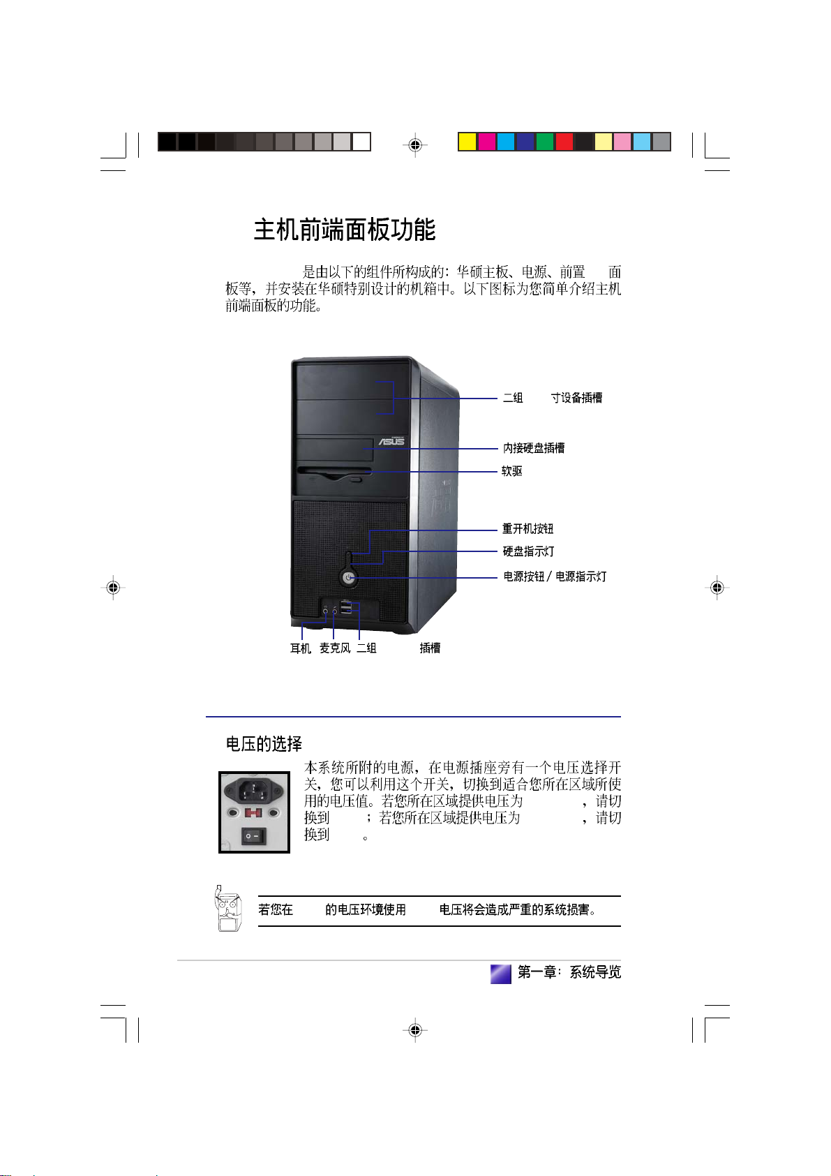
1.1
1.2
1.3
1.4
1.5
................................................................................
........................................................................................
........................................................................
........................................................................
................................................................................
11
12
14
15
16
Page 11
1.1
1.
2.
3.
4.
11
Page 12
1.2
1. Introduction
Intel 800MHz FSB
478
ZIF Socket-478 Pentium®4 512/256KB
L2 0.13 800/533/400MHz
6.4GB 4.3GB 3.2GB
Intel®Hyper-Threading Prescott
SiS661FX/963L
SiS¤ 661FX/963L SiS
SiS® 661FX
Intel® Pentium® 4 AGP 8X
AGP 1.5V 800MHz DDR400
SiS® 661FX HyperStreamingTM
SiS963L
ATA133 IDE USB 2.0/1.1
SiS963L LPC
AC 97 APM Advanced Power
Management 1.2 SiS MuTIOL
SiS963L 1GB
®
®
12
DDR400
PC3200/2700/
2100/1600 non-ECC DDR SDRAM Double Data Rate SDRAM
2GB
SDRAM 3.2GB
10/100 Mbps LAN
VIA 6103L LAN PHY SiS963L
10BASE-T/100BASE-TX
Page 13
Real256E
SiS Real256E 256 bit 3D
2D 64MB SiS Real256E
UltraAGPIITM
throughout 3.2GB
SiS Real256E
2048 x 1526 32bpp
USB 2.0
USB USB 2.0
USB USB
USB USB USB USB 2.0
USB 1.1 12 Mbps USB 2.0 480 Mbps
USB 2.0
USB 2.0 USB 1.1
VGA
13
Page 14
1.3
1. Introduction
Vintage-S800 I/O
5.25
14
USB 2.0
100-127V
115V 200-240V
230V
230V 115V
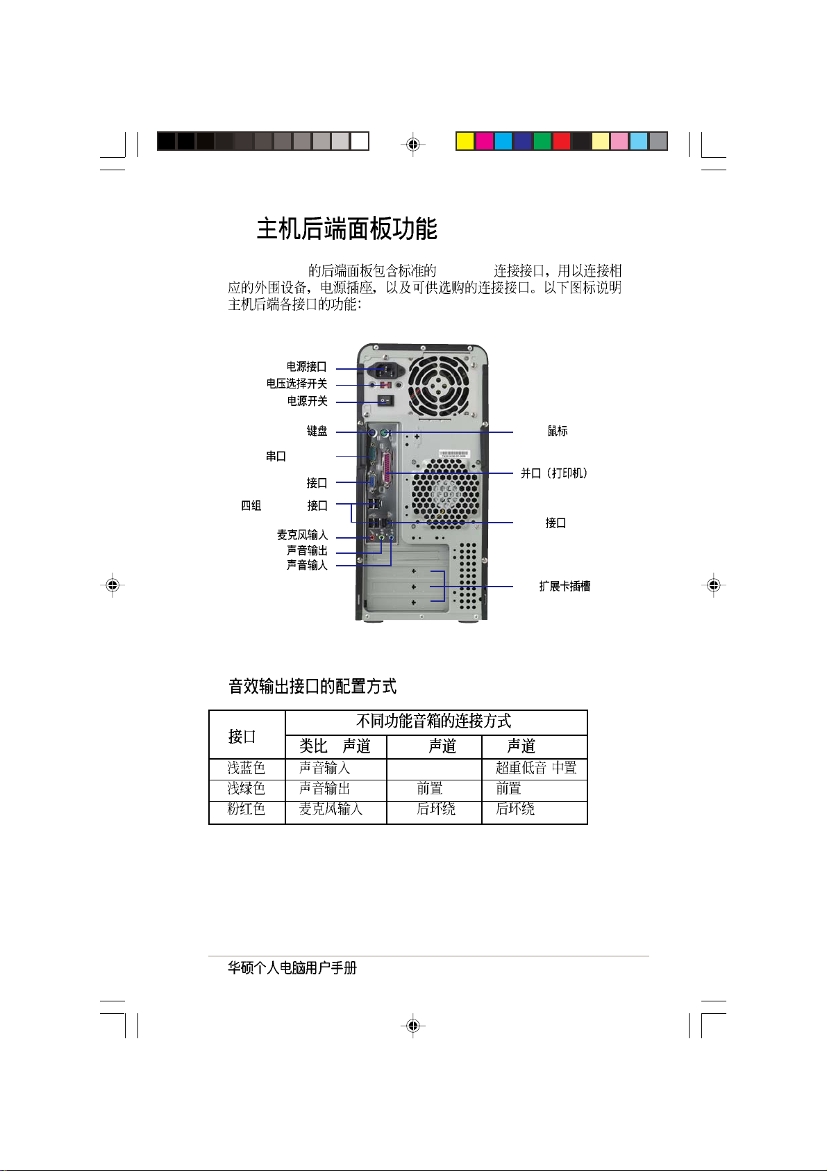
Page 15
1.4
Vintage-S800 PC99 I/O
(COM1)
VGA
USB 2.0
PS/2 PS/2
LAN (RJ-45)
PCI
2 4 6
- /
15
Page 16
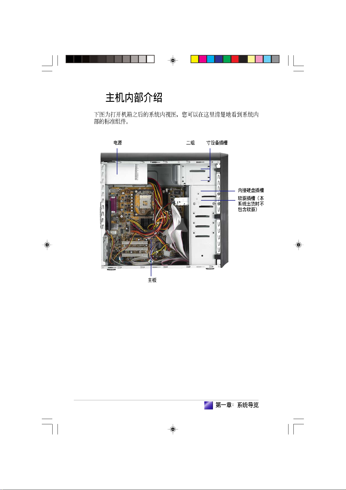
1.5
5.25
16
Page 17
step-by-step
Page 18
2.1
2.2
2.2.1
2.2.2
2.3 CPU
2.3.1 CPU
2.3.2
2.3.3 CPU
2.4
2.4.1
2.4.2
2.4.3
2.5
2.5.1 IDE
2.5.2
2.6
2.6.1
2.6.2 PCI
2.6.3 AGP
2.6.4
2.7
2.8
2.9
....................................................................................
........................................................................................
............................................................................
............................................................................
........................................................................................
....................................................................................
................................................................................
................................................................................
........................................................................................
....................................................................................
............................................................................................
................................................................................
................................................................................
........................................................................................
........................................................................................
19
21
20
21
....................................................................
..........................................................................
........................................................................
..........................................................................
...........................................................................
.........................................................................
.......................................................................
........................................................................
22
22
24
25
26
26
27
28
29
29
30
31
31
32
32
33
34
35
36
Page 19
2.1
d
1.
2.
3.
4.
5.
/
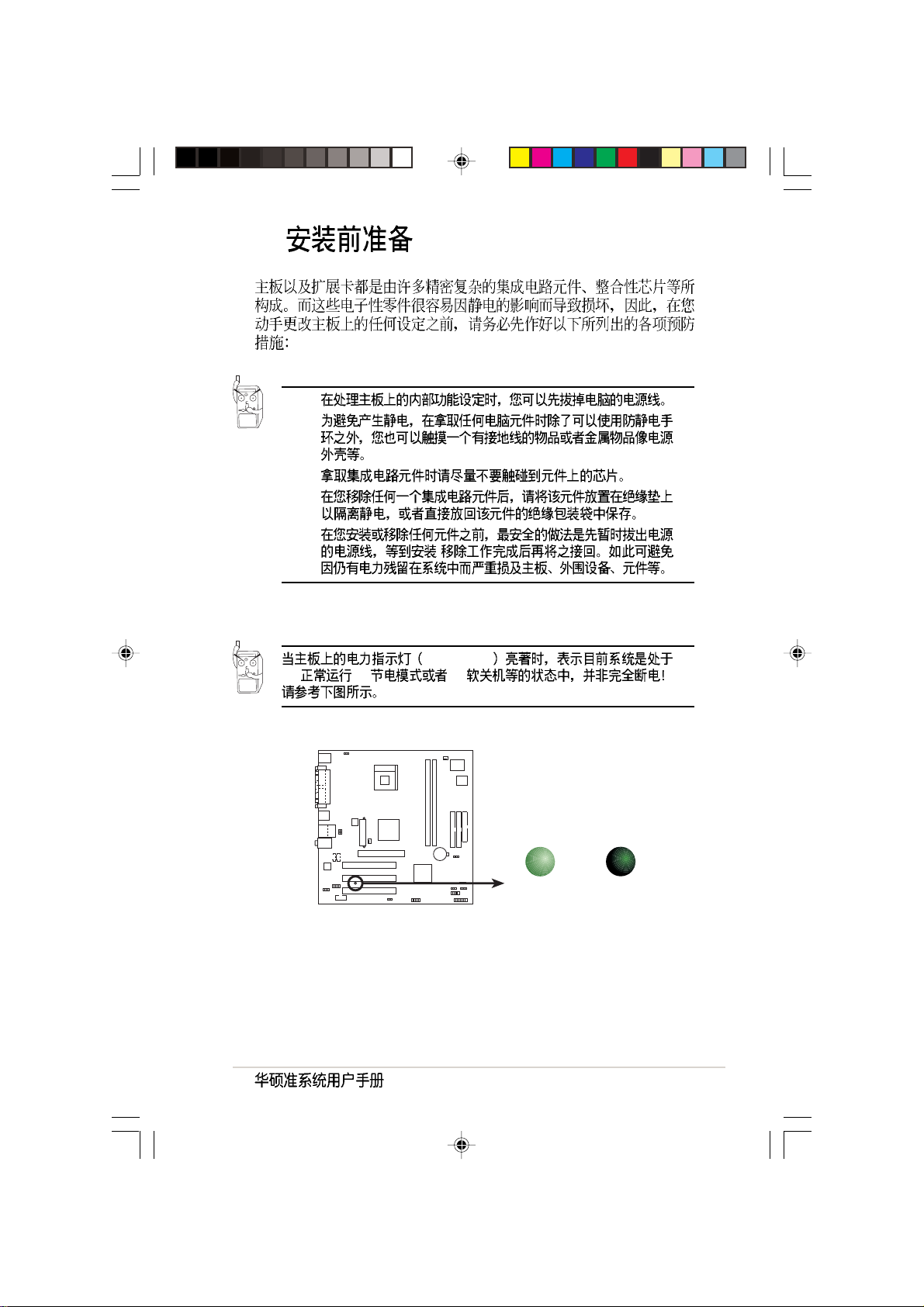
SB_PWR1
(1) (2) (3)
Onboard LED
ON
Standby
Power
SB_PWR1
OFF
Powere
Off
19
Page 20
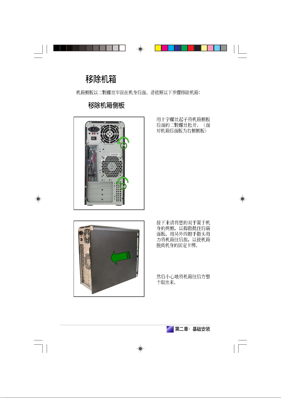
2.2
2.2.1
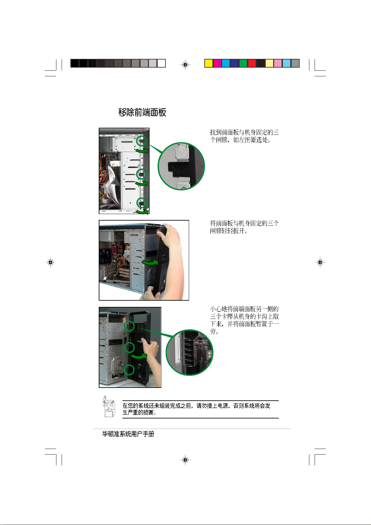
1.
20
2.
3.
Page 21
2.2.2
1.
2.
3.
21
Page 22
2.3 CPU
Vintage-S800 478
ZIF Intel Pentium 4 CPU
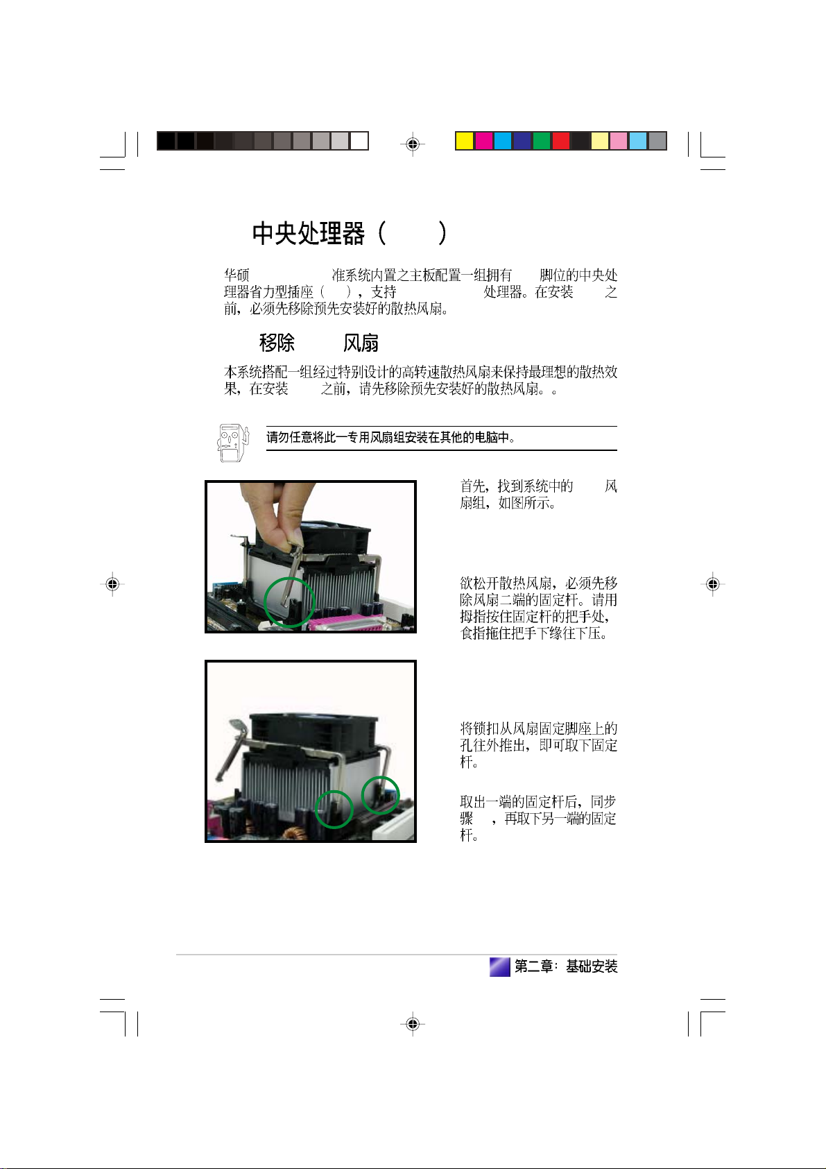
2.3.1 CPU
CPU
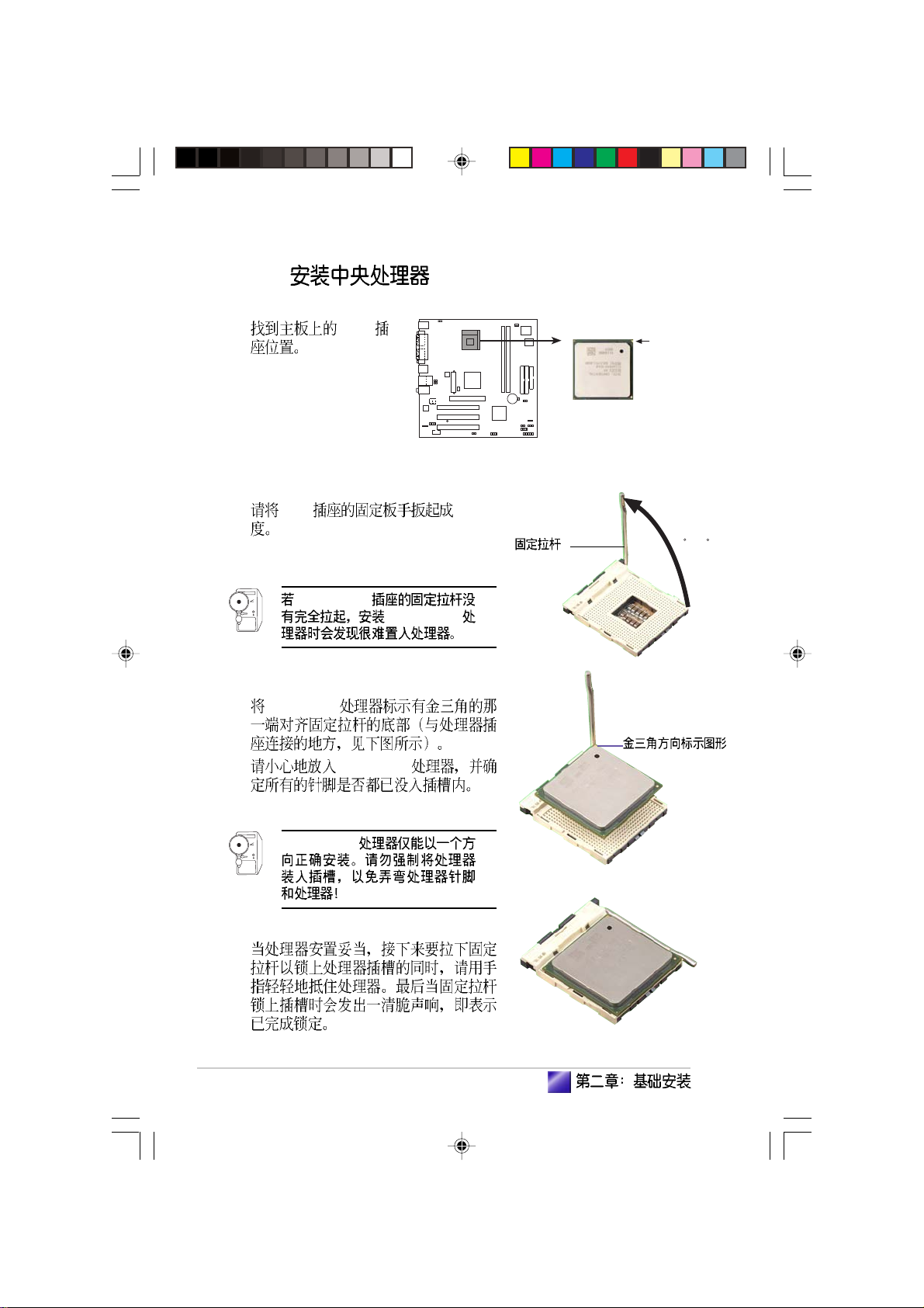
1. CPU
2.
22
3.
4.
2-3
Page 23
5.
6.
23
Page 24
2.3.2
0
1. CPU
CPU Socket 478
2. CPU 90-100
Socket-478
3. Pentium
®
4
4. Pentium
Pentium
®
®
4
4
Gold Arrow
90 -10
Pentium
®
4
5.
24
Page 25
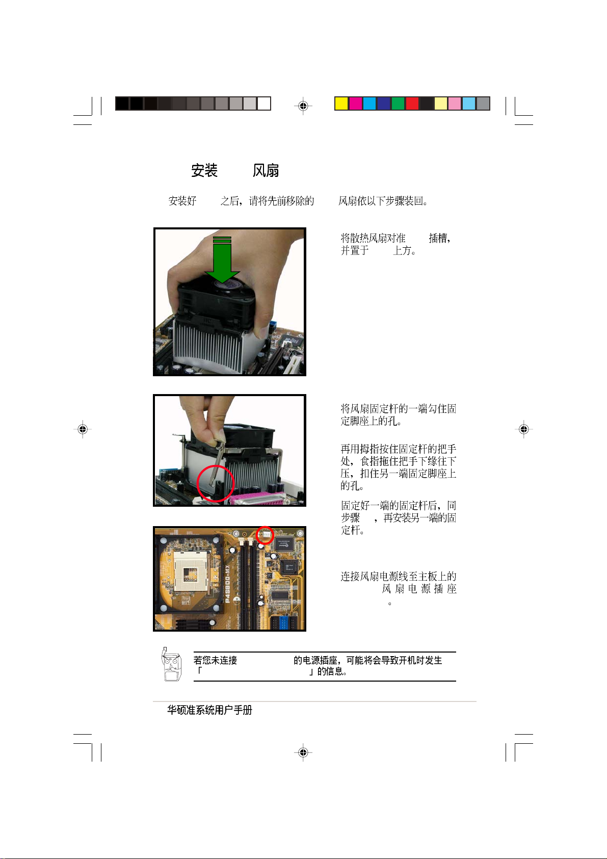
2.3.3 CPU
CPU CPU
1. CPU
CPU
2.
3.
CPU_FAN1
Hardware monitoring errors
4.
2-3
5.
CPU
CPU_FAN1
25
Page 26
2.4
184-pin DDR DIMM Double Data Rate
unbuffered non-ECC PC3200/2700/
2100/1600 DDR DIMM 2 GB
1.
2. AGP
AGP
2.4.1
64 128 256 512MB 1GB DDR DIMM
DDR400
/www.asus.com
http:/
1 DDR400
/
512MB MICRON MT16VDDT6464AG-40BC4 MICRON DS MT46V32M8TG-5BC
512MB CENTURY DXV2S8SSCCE3K27E SAMSUNG DS K4H560838E-TCCC
256MB CENTURY DXV6S8MC5BC3U27E MICRON SS MT46V32M8TG-5BC
256MB BRAIN POWER B6U808-256M-SAM-400 SAMSUNG SS K4H560838D-TCC4
256MB Transcend TS32MLD64V4F3 MOSEL SS V58C2256804SAT5
256MB Apacer 77.10636.465 SAMSUNG SS K4H560838D-TCC4
256MB ATP AG32L64T8SQC4S SAMSUNG SS K4H560838D-TCC4
256MB NANYA NT256D64S88B1G-5T NANYA SS NT5DS32M8BT-5T
256MB MICRON MT8VDDT3264AG-40BC4 MICRON SS MT46V32M8TG-5BC
512MB elixir M2U25664DS8HB3G-5T elixir DS N2DS25680BT-5T
SS - DIMM
DS - DIMM
26
Page 27
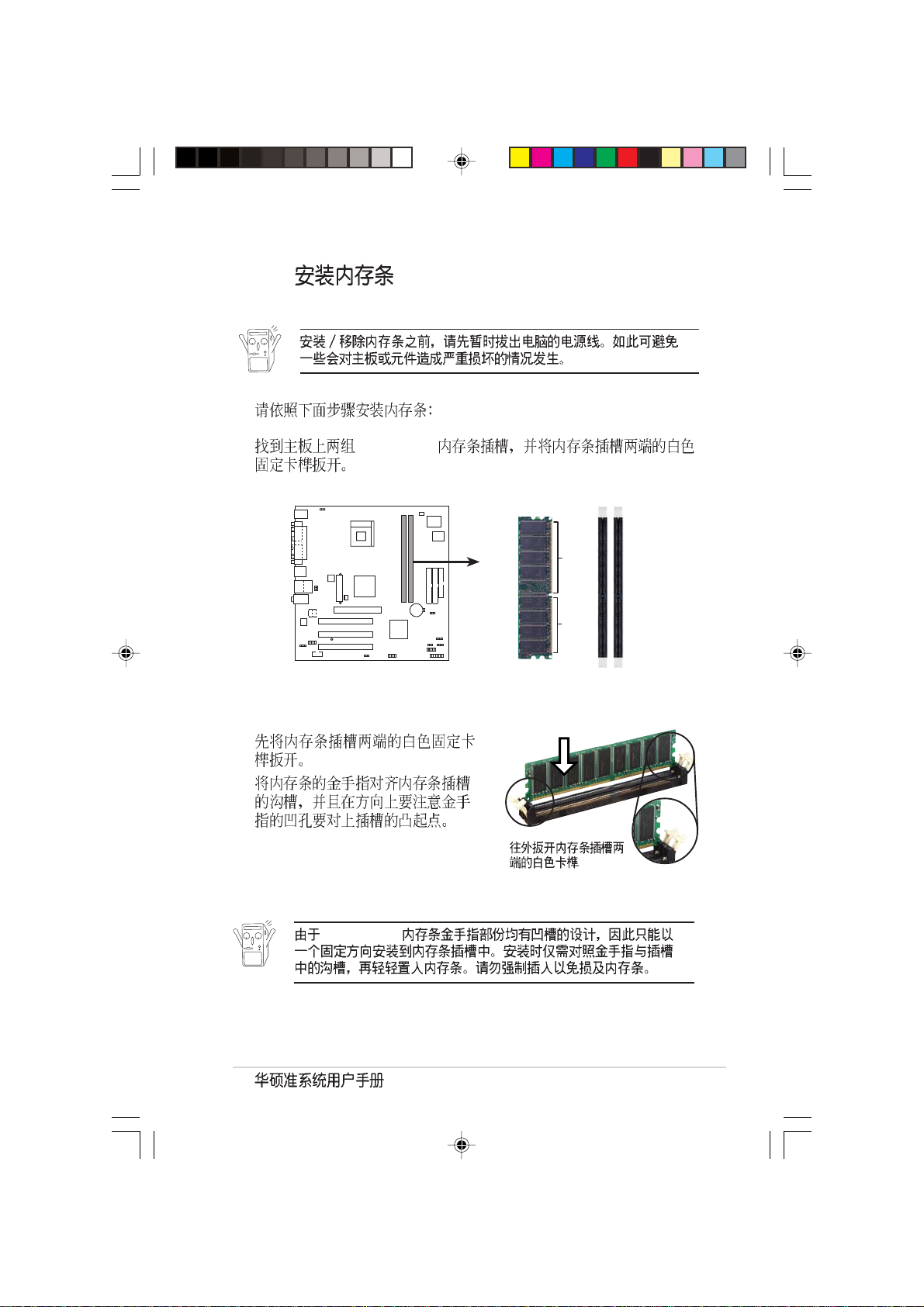
2.4.2
1. DDR DIMM
184-Pin DDR DIMM sockets
80 Pins 104 Pins
DIMM1
DIMM2
2.
3.
DDR DIMM
27
Page 28
4.
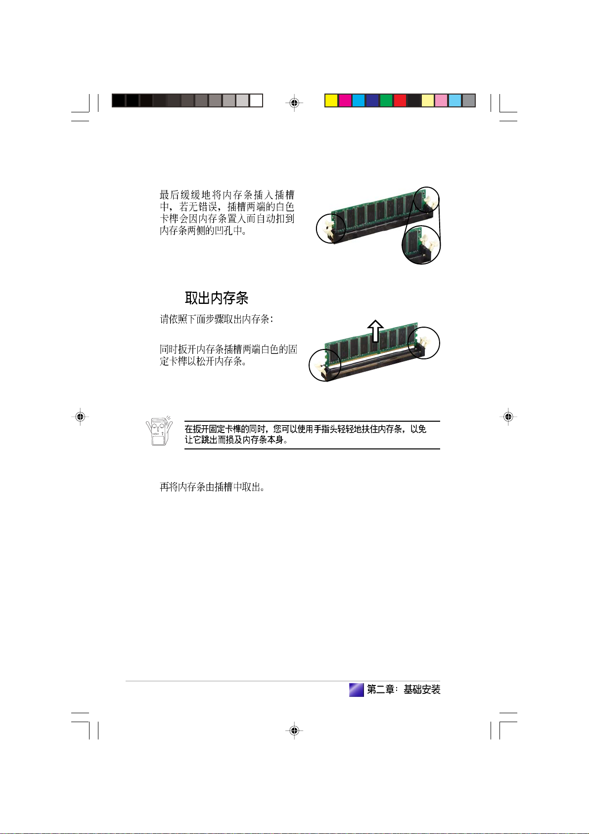
2.4.3
1.
28
2.
Page 29
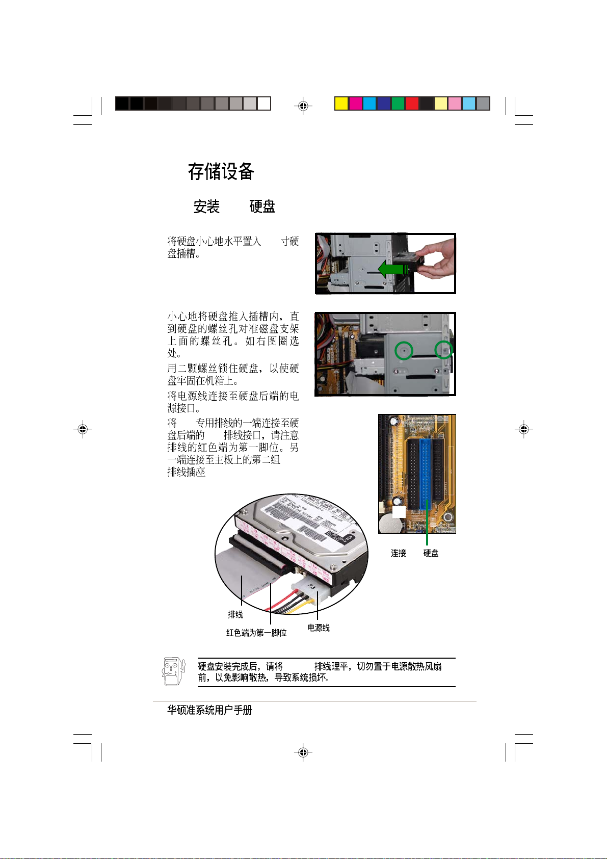
2.5
2.5.1 IDE
1. 3.5
2.
3.
4.
5. IDE
IDE
IDE
IDE
IDE
IDE
29
Page 30

2.5.2
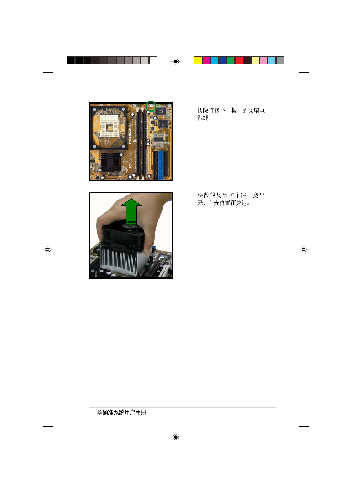
1.
2.
3.
4. IDE
IDE
5.
4-pin
CD-ROM/CD-RW/DVD-ROM/DVD-RW
CD-ROM
CD-ROM (CD1)
30
IDE
6. IDE
IDE
7.
CD1 4-pin
IDE
Page 31

2.6
2.6.1
32-bit PCI AGP
1.
2.
3.
4.
PCI
AGP
31
Page 32

2.6.2 PCI
SCSI USB PCI
PCI PCI PCI
2.6.3 AGP
AGP 8X AGP
AGP 1.5V
AGP
32
3.3V AGP 1.5V
AGP
Keyed for 1.5v
Accelerated Graphics Port (AGP)
Page 33

2.6.4
1. BIOS
BIOS
2. IRQ
3.
IRQ
01
12
2 N/A
3* 11 COM 2
4* 12 COM 1
5* 13
614
7* 15 LPT 1
83 CMOS/
9* 4 ACPI
10* 5 PCI
11* 6 PCI
12* 7 PS/2
13 8
14* 9 IDE
15* 10 IDE
*
( LPT2)
ABCDEFGH
1 PCI ------ 2 PCI - ----- 3 PCI -- -----
AGP -------
USB 1 ---- -- USB 2 ----- - USB 2.0 -------
--- ----
-- -----
33
Page 34

2.7
1.
2.
34
3.
Page 35

2.8
PS/2
PS/2
VGA
USB
RJ-45
AGP
PCI
35
Page 36

2.9
Min Nom Max
1 90V 115V 135V
2 180V 230V 265V
47 Hz to 63 Hz
AC 4A max at 115Vac
2A max. at 230Vac, maximum load
NOTES 90A max. at 115Vac,
full load cold start at 25
70% min. at nominal input,
maximum load
Output Load Range Regulation Ripple
Voltage Min Max Min Max Max
+5V 0.5A 4.0A -5% +5% 50mV
+12V 0.45A 9.5A -5% +5% 120mV
-12V 0A 0.2A -10% +10% 120mV
+5Vsb 0.05A 1.5A -5% +5% 50mV
+3V3 1A 8.0A -5% +5% 50mV
p-p
p-p
p-p
p-p
p-p
36
Over-Voltage Protection (OVP)
+5V 6.5V
+12V 15.6V
+3.3V 4.3V
+5V +12V -12V +3.3V
+5Vsb
Page 37

Page 38

3.1
3.2
3.3
3.3.1
3.3.2 Drivers Menu
3.3.3 Utilities Menu
3.3.4
3.4
................................................................................
........................................................................................
....................................................
........................................................................
............................................................................
39
39
40
................................................
......................................
.....................................
40
41
41
42
43
Page 39

3.1
3.2
Windows 2000/XP
Windows Windows
Windows
Windows
Windows
39
Page 40

3.3
3.3.1
http://www.asus.com.cn
40
Page 41

3.3.2 Drivers Menu
SiS AGP
SiS AGP
SiS VGA
SiS VGA
SoundMAX &
SoundMAX
SiS PCI
SiS PCI
3.3.3 Utilities Menu
ASUS PC Probe
41
Page 42

ASUS Live Update
BIOS
Microsoft DirectX 8.1
DirectX
Adobe Acrobat Reader
Adobe Acrobat Reader PDF Portable Document
Format
3.3.4
42
Page 43

3.4
CPU
Show up in next execution
\
- ASUS Utility\Probe Vx.xx Vx.xx
Tray
43
Page 44

CPU
CPU
CPU
CPU
CPU
44
Page 45

CPU
Always CPU
CPU Overheated CPU
CPU
When
CPU
FAT
45
Page 46

46
DMI
CPU
CPU
Page 47

CPU !!!
47
Page 48

48
Page 49

Jumper
BIOS
<Del> BIOS
( )
Page 50

4.1
4.2
4.3
4.4
4.4.1
4.4.2
................................................................................................
....................................................................................
........................................................................
................................................................
............................................................................
............................................................................
51
51
52
54
54
55
Page 51

4.1
24.5cm (9.6in)
4.2
PS/2KBMS
T: Mouse
B: Keyboard
COM1
VGA1
USB1
USB2
USB2.0
T: USB3
B: USB4
Top:Line In
Center:Line Out
Below:Mic In
AD1888
CODEC
SPDIF_OUT1
KBPWR1
+5V +5VSB
(Default)
PARALLEL PORT
Top:
RJ-45
FP_AUDIO1
COM2
2312
USBPW12
USBPW34
CD1AUX1
KBPWR1
ATX12V1
ATX Power Connector
CHA_FAN1
Accelerated Graphics Port (AGP1)
PCI1
PCI2
SB_PWR1
PCI3
USBPW12
USBPW34
3
2
2
1
+5V
+5VSB
(Default)
Socket 478
North Bridge
USBPW56
+5V
(Default)
SiS
661FX
+5VSB
USBPW56
2321
Chipset
CLRTC1
12 23
Normal Clear CMOS
(Default)
CPU_FAN1
Super
DDR DIMM1 (64 bit,184-pin module)
DDR DIMM2 (64 bit,184-pin module)
CR2032 3V
Lithium Cell
CMOS Power
SiS
963L
F_PANEL1
PLED1
1
PLED+
NC
PLED-
*
GAME1
F_PANEL1
PLED
HDLED
Requires an ATX power supply.
USB56
I/O
SEC_IDE1
PLED-
PLED+
HDLED-
HDLED+
RESET
2Mb
ISA
PRI_IDE1
CLRTC1
CHASSIS1
SPEAKER1PLED1
PWRBTN
PWR
GNDReset
Ground
FLOPPY1
24.5cm (9.6in)
51
Page 52

S
4.3
1. CMOS CLRTC1
CMOS
CMOS
1
2
3 CLRTC1 [1-2] [2-3]
CMOS [1-2]
4
5
6 <Del> BIOS
BIOS
CMOS
52
CLRTC1
12 23
Normal Clear CMO
(Default)
Clear RTC RAM
CMOS C.P.R. CPU
BIOS
Page 53

2. USB 3-pin USBPW12, USBPW34,
USBPW56
+5V USB S1
+5VSB S3 S4
USB
+5V [1-2]
USBPWR12 USBPWR34
USB USBPWR56 USB
1. USB +5VSB
1A/+5VSB
2.
+5VSB
USBPW12
USBPW34
3
2
USBPW56
+5VSB
2321
+5VSB
USB device wake-up
2
1
+5V
(Default)
+5V
(Default)
3. 3-pin KBPWR1
KBPWR1 [2-3]
+5VSB
1A/+5VSB BIOS
[1-2] +5V
(Default)
Keyboard power setting
KBPWR1
2312
+5V +5VSB
53
Page 54

4.4
1
2 3
4.4.1
4
5
6
11
1. PS/2 PS/2
2.
3. RJ-45 LAN Local Area
Network
4.
5.
6.
910
8
7
54
Page 55

s
7. USB 2.0 1 2 USB
USB 2.0
8. USB 2.0 3 4 USB
USB 2.0
9. VGA VGA VGA
10. 9-pin
11. PS/2 PS/2
4.4.2
1. IDE 40-1 pin PRI_IDE1, SEC_IDE1
IDE
IDE CD-ROM ZIP MO
Primary
Secondary Slave
UltraATA133 IDE
Master UltraATA133 IDE
1. IDE
Master
Slave
2. IDE
UltraDMA
3. UltraATA
IDE connectors
SEC_IDE1
PIN 1
NOTE: Orient the red marking
(usually zigzag) on the IDE
ribbon cable to PIN 1.
PRI_IDE1
Pin 1
55
Page 56

2. 20-pin ATXPWR1, 4-pin ATX12V1
ATX 12V
20 ATXPWR1
+12V
ATX 12V +5V 20
+5VSB 1
230
300
56
ATX Power connector
+12V DC
GND
ATX12V1
+12V DC
GND
ATXPWR1
+12.0VDC
+5VSB
PWR_OK
COM
+5.0VDC
COM
+5.0VDC
COM
+3.3VDC
+3.3VDC
+5.0VDC
+5.0VDC
-5.0VDC
COM
COM
COM
PS_ON#
COM
-12.0VDC
+3.3VDC
Page 57

3. 34-1 pin FLOPPY1
n
FLOPPY1
NOTE: Orient the red markings o
the floppy ribbon cable to PIN 1.
Pin 1
PIN 1
Floppy disk drive connector
4. 10-1 FP_AUDIO1
Intel
/
LINE OUT_R/BLINE_OUT_R
LINE OUT_L/BLINE_OUT_L
Front panel audio connector
FP_AUDIO1
AGND
MIC2
+5VA
MICPWR
BLINE_OUT_L
BLINE_OUT_R
NC
Line out_L
Line out_R
57
Page 58

5. 3-pin CPU_FAN1,
1
1
CHA_FAN1
350 4.2 1 12 /+12
+12V GND
CPU_FAN
GND
Rotation
+12V
CHA_FAN
GND
+12V
Rotation
58
Fan connectors
Page 59

6. USB 10-1 pin USB56
USB
USB USB
USB USB USB 2.0
480 Mbps USB 1.1 12 Mbps 40
USB+5V
USB56
USB connector
USB
1
USB+5V
7. 4-1 pin SPDIF_OUT1
S/PDIF S/PDIF
USB_P6-
USB_P6+
GND
GND
USB_P5-
USB_P5+
NC
Digital audio connector
S PSIF
SPDIF_OUT1
GND
+5V
SPDIFOUT
59
Page 60

1
)
8. 4-pin AUX1, CD1
MPEG
Left Audio Channel
Right Audio Channel
Internal audio connectors
9. 4-pin SPEAK1
Speaker out connector
AUX1 (White)
Ground
Ground
SPEAKER
1
+5V
GND
GND
CD1 (Black
Speak Out
60
Page 61

10. /MIDI 16-1 pin GAME1
MIDI
MIDI MIDI
MIDI
MIDI
+5V
J2B1
J2CX
MIDI_OUT
GAME1
Game connector
MIDI
+5V
J1B1
J1CX
GND
11. 3-1 pin PLED1
J2CY
GND
J2B2
MIDI_IN
J1B2
J1CY
+5V
PLED setting
PLED1 1.03
PLED1
1
NC
PLED+
PLED-
61
Page 62

12. 20-pin F_PANEL1
y.
PLED
F_PANEL1
PWRBTN
PLED-
PWR
PLED+
Ground
HDLED-
HDLED+
GNDReset
*
System panel connector
•
3-1 pin PLED
Requires an ATX power suppl
2-pin 3-pin 2-pin
3-pin
ATX / 2-pin PWR_BTN
•
BIOS
IDE 2-pin IDE_LED
•
IDE_LED IDE
IDE
HDLED
RESET
62
•
2-pin RESET
Reset
Page 63

BIOS
BIOS
( )
BIOS
BIOS
<Del> BIOS
Page 64

5.1 BIOS
5.1.1
5.1.2 AFUDOS BIOS
5.1.3 AFUDOS BIOS
5.1.4 EZ Flash BIOS
5.2 BIOS
5.2.1 BIOS
5.3 Main Menu
5.3.1 System Time [XX:XX:XX]
5.3.2 System Date [XX/XX/XXXX]
5.3.3 Legacy Diskette A [1.44M, 3.5 in.]
5.3.4 IDE Primary/Secondary IDE Master/Slave
5.3.5 System Information
5.4 Advanced menu
5.4.1 JumperFree
5.4.2 CPU Configuration
5.4.3 Chipset
5.4.4 OnBoard Devices Configuration
5.4.5 PCI PCI PnP
5.4.6 USB USB Configuration
5.5 Power menu
5.5.1 ACPI AWARE O/S
5.5.2 Suspend Mode [Auto]
5.5.3 Repost Video on S3 Resume [No]
5.5.4 ACPI APIC Support [Enabled]
5.5.5 APM Configuration
5.5.6 Hardware Monitor
5.6 Boot menu
5.6.1 Boot Device Priority
5.6.2 Boot Settings Configuration
5.6.3 Security
5.7 BIOS Exit menu
........................................................................
..............................................................................
.........................................................
.......................................
.......................................
........................................
...................................................................
.................................................................
.........................................................
....................................................
.............................................
.............................................
......................................................
.................................................................
..........................................
.................................................................
................................................
.............................................
............................................................
.....................................................................
.................................................................
..............................................
...................................................
.............................
.......................................
..............................................................
....................................
........................
............................................................
....................................................
.........
.................
65
65
66
67
68
70
71
73
73
73
73
74
75
76
76
77
78
81
82
83
84
84
84
84
84
85
87
88
88
89
90
93
64
BIOS
Page 65

5.1 BIOS
BIOS Basic Input/Output
System
1. ASUS EZ Flash Power-On Self
Test POST BIOS
2. ASUS AFLASH DOS BIOS
3. ASUS CrashFree BIOS BIOS BIOS
4. ASUS Update Windows BIOS
1. BIOS
BIOS AFLASH
BIOS
2. http://www.asus.com.tw
BIOS
5.1.1
1.
DOS
1.44MB DOS
format A:/S <Enter>
Windows
a. Windows
b. /
c.
d. 1.44MB
2. BIOS
65
Page 66

5.1.2 AFUDOS BIOS
AFUDOS.EXE BIOS
BIOS
1. DOS
afudos/0<filename>
filename
BIOS
A:\>afudos /oMYBIOS03.rom
AMI Firmware Update Utility - Version 1.10
Copyright (C) 2002 American Megatrends, Inc. All rights reserved.
Reading flash ..... 0x0008CC00 (9%)
2. BIOS
600KB
A:\>afudos /oMYBIOS03.rom
AMI Firmware Update Utility - Version 1.10
Copyright (C) 2002 American Megatrends, Inc. All rights reserved.
Reading flash ..... done
A:\>
BIOS DOS
66
BIOS
Page 67

5.1.3 AFUDOS BIOS
DOS AFUDOS.EXE BIOS
1. www.asus.com.tw BIOS
BIOS
BIOS
2. AFUDOS.EXE
BIOS
3.
4. DOS
afudos/i<filename>
filename
BIOS
BIOS
A:\>afudos /iP4X800-MX.rom
AMI Firmware Update Utility - Version 1.10
Copyright (C) 2002 American Megatrends, Inc. All rights reserved.
Reading file ..... done
Erasing flash .... done
Writing flash .... 0x0008CC00 (9%)
BIOS
DOS
67
Page 68

A:\>afudos /iP4X800-MX.rom
AMI Firmware Update Utility - Version 1.10
Copyright (C) 2002 American Megatrends, Inc. All rights reserved.
Reading file ..... done
Erasing flash .... done
Writing flash .... 0x0008CC00 (9%)
Verifying flash .. done
A:\>
5.1.4 EZ Flash BIOS
EZ Flash BIOS
DOS EZ Flash BIOS
Power-On Self
Test POST <Alt> + <F2> EZ Flash
EZ Flash BIOS
1. www.asus.com.tw BIOS
P4S800MX.BIN
2.
3. POST <Alt> + <F2>
EZ Flash
User recovery requested. Starting BIOS recovery...
Checking for floppy...
•
Floppy not found
•
P4S800MX.BIN not found
BIOS P4S800MX.BIN
BIOS
68
BIOS
Page 69

4. BIOS
EZ Flash BIOS
BIOS
User recovery requested. Starting BIOS recovery...
Checking for floppy...
Floppy found!
Reading file “p4s800-mx.bin”. Completed.
Start flashing...
Flashed successfully. Rebooting.
69
Page 70

5.2 BIOS
BIOS Basic Input and Output System
RUN SETUP BIOS
BIOS
EEPROM BIOS EEP ROM
BIOS BIOS
BIOS
CMOS RAM
BIOS
POST Power-On Self Test
Del
BIOS
BIOS
70
BIOS
BIOS
Page 71

5.2.1 BIOS
System Time [17:08:35]
System Date [Mon 04/19/2004]
Legacy Diskette A [1.44M, 3.5 in.]
Primary IDE Master [ST320410A]
Primary IDE Slave [Pioneer CD-ROM ATA]
Seconday IDE Master [Not Detected]
Secondary IDE Slave [Not Detected]
System Information
BIOS
Main
Advanced
Power
Boot
Exit BIOS
Use [ENTER], [TAB] or
[SHIFT-TAB] to select a
field.
Use [+] or [-] to
configure system time.
71
Page 72

[ Enter ]
System Time [17:08:35]
System Date [Mon 04/19/2004]
Legacy Diskette A [1.44M, 3.5 in.]
Primary IDE Master [ST320410A]
Primary IDE Slave [Pioneer CD-ROM ATA]
Seconday IDE Master [Not Detected]
Secondary IDE Slave [Not Detected]
System Information
[ Enter ]
Primary Graphics Adapter [AGP]
Search for MDA Resources [Yes]
AGP Mode [AGP 8X]
AGP Fast Write [Enabled]
Graphics Aperture Size [64MB]
Options
Enabled
Disabled
Use [ENTER], [TAB]
or [SHIFT-TAB] to
select a field.
Use [+] or [-] to
configure System
Time.
72
/ PageUp/ PageDown
BIOS
Page 73

5.3 Main Menu
BIOS
System Time [17:08:35]
System Date [Mon 04/19/2004]
Legacy Diskette A [1.44M, 3.5 in.]
Language [English]
Primary IDE Master [ST320410A]
Primary IDE Slave [Pioneer CD-ROM ATA]
Seconday IDE Master [Not Detected]
Secondary IDE Slave [Not Detected]
System Information
Use [ENTER], [TAB] or
[SHIFT-TAB] to select a
field.
Use [+] or [-] to
configure system time.
5.3.1 System Time [XX:XX:XX]
00 23 00 59 00 59 Tab
Tab + Shift
5.3.2 System Date [XX/XX/XXXX]
1 12 1 31 00 99 Tab
Tab + Shift
5.3.3 Legacy Diskette A [1.44M, 3.5 in.]
[360K 5.25 in.] [1.2M 5.
25 in.] [720K 3.5 in.] [1.44M 3.5 in,] [2.88M 3.5 in.][None]
73
Page 74

5.3.4 IDE Primary/Secondary IDE
Master/Slave
BIOS IDE
ATA IDE ATA
[Enter]
Primary IDE Master
Device : Hard Disk
Vendor : ST320410A
Size : 20.0GB
LBA Mode : Supported
Block Mode : 16 Sectors
PIO Mode : 4
Async DMA : MultiWord DMA-2
Ultra DMA : Ultra DMA-5
SMART Monitoring: Supported
Type [Auto]
LBA/Large Mode [Auto]
Block (Multi-Sector Transfer) M [Auto]
PIO Mode [Auto]
SMART Monitoring [Auto]
32Bit Data Transfer [Disabled]
Select the type of
device connected to the
system.
BIOS
N/A
Type [Auto]
IDE Auto
IDE CDROM IDE
ARMD (ATAPI )
IDE ZIP LS-120 MO [Not
Installed] [Auto] [CDROM] [ARMD]
LBA/Large Mode [Auto]
LBA [Auto]
LBA LBA
[Disabled] [Auto]
Block (Multi-sector Transfer) [Auto]
[Disabled][Auto]
74
[Auto]
[Disabled]
BIOS
Page 75

PIO Mode [Auto]
PIO [Auto] [0] [1] [2] [3] [4]
SMART Monitoring [Auto]
Smart Monitoring, Analysis, and Reporting
Technology [Auto] [Disabled] [Enabled]
32Bit Data Transfer [Disabled]
32 [Disabled] [Enabled]
5.3.5 System Information
BIOS
AMI BIOS
Version : 08.00.09
Build Date : 04/23/04
ID : A0088001
Processor
Type : Intel (R) Pentium (R) 4 Family
CPU 2.40 G
Speed : 2400MHz
Count: : 1
System Memory
Size : 224MB
AMI BIOS
Processor
System Memory
BIOS
75
Page 76

5.4 Advanced menu
JumperFree Configuration
CPU Configuration
Chipset
Onboard Devices Configuration
PCIPnP
USB Configuration
5.4.1 JumperFree
JumperFree
AI Overclock Tuner [Standard]
DRAM Frequency [Auto]
Configure System Frequency/Voltage
Configure CPU.
76
BIOS
Page 77

AI Overclock Tuner [Standard]
[Standard] [Manual]
CPU 100 - 300
[Standard] [Manual]
DRAM Frequency [Auto]
DDR [200 MHz] [266 MHz]
[333 MHz] [400 MHz] [450 MHz] [533 MHz] [Auto]
5.4.2 CPU Configuration
Configure Advanced CPU settings
Manufacturer: Intel(R)
Brand String: Intel(R) Pentium(R) 4 Family CPU
2.40G
Frequency : 2400Mhz
FSB Speed : 533Mhz
Cache L1 : 8 KB
Cache L2 : 512 KB
Cache L3 : 0 KB
Rario Status: Locked
Ratio Actual Value: 18
VID CMOS Setting: [ 62]
Max CPUID Value Limit: [Disabled]
CPU Internal Thermal Control [Auto]
VID CMOS Setting [ 62]
VID CMOS
Max CPUID Value Limit [Disabled]
extended CPUID CPU
[Enabled] [Disabled] [Enabled]CPU Internal
Thermal Control [Auto]
CPU Internal Thermal Control [Auto]
[Auto] [Disabled]
Sets the ration between
CPU Core Clock and the
FSB Freuency.
Note: If an invalid
ratio is set in CMOS,
then actual and setpoint
values may differ.
77
Page 78

5.4.3 Chipset
<Enter>
Northbridge SiS661FX Configuration
Southbridge SiS963/SiS963L Configuration
SiS661FX NorthBridget
Primary Graphics Adapter [PCI]
MA 1T/2T Select [Auto]
DRAM CAS# Latency [By SPD]
DRAM Precharge Delay [Auto]
DRAM RAS# to CAS# Delay [Auto]
DRAM RAS# Precharge [Auto]
Graphic Win Size [ 64MB]
Share Memory Size [ 32MB]
Options for NB.
Select which graphics
controller to use as the
primary boot device.
78
BIOS
Page 79

Primary Graphics Adapter [PCI]
[AGP] [Onboard AGP]
MA 1T/2T Select [Auto]
[MA2T] [MA1T]
DRAM CAS# Latency [By SPD]
SDRAM
SPD] [2T] [2.5T] [3T]
DRAM Precharge Delay [Auto]
[Auto] [6T] [7T] [5T] [4T] [8T] [9T]
DRAM RAS# to CAS# Delay [Auto]
SDRAM /
[Auto] [3T] [2T] [4T] [5T]
DRAM RAS# Precharge [Auto]
SDRAM Precharge
[Auto] [3T] [2T] [4T] [5T]
[PCI]
[By
Graphic Win Size [ 64MB]
[32MB] [64MB] [128MB]
Share Memory Size [ 32MB]
[16MB] [32MB] [64MB] [128MB] [Disabled]
79
Page 80

SiS963/SiS963L SouthBridget
Onboard AC97 Audio Device [Enabled]
Onboard SiS900 LAN Device [Enabled]
Onboard LAN Boot ROM [Disabled]
Onboard AC97 Audio Device [Auto]
AC97
[Auto][Disabled]
Onboard Sis900 LAN Device [Enabled]
[Enabled]
Onboard LAN Boot ROM [Disabled]
[Disabled]
ROM [Disabled] [Enabled]
80
Boot
BIOS
Page 81

5.4.4 OnBoard Devices
Configuration
Configure Win697 Super IO Chipset
Serial Port1 Address [3F8/IRQ4]
Serial Port2 Address [2F8/IRQ3]
Parallel Port Address [Disabled]
Onboard Game Port [Disabled]
Onboard MIDI Port [Disabled]
Serial Port1 Address [3F8/IRQ4]
COM 1 COM 1 COM 2
[Disabled] [3F8/IRQ4] [3E8/IRQ4] [2E8/IRQ3]
Serial Port2 Address [2F8/IRQ3]
COM 1 COM 1 COM 2
[Disabled] [2F8/IRQ3] [3E8/IRQ4] [2E8/IRQ3]
Parallel Port Address [Disabled]
[Disabled]
Allows BIOS to select
Serial Port1 Base
Addresses.
[378] [278] [3BC]
Onboard Game Port [Disabled]
[Disabled] [Enables]
Onboard MIDI Port [Disabled]
[Disabled] [300] [330]
81
Page 82

5.4.5 PCI PCI PnP
PCI/PnP PCI/PnP
IRQ DMA
Advanced PCI/PnP settings
WARNING: Setting wrong values in the sections below
may cause system to malfunction.
Plug And Play OS [No]
PCI Latency Timer [64]
Allocate IRQ to PCI VGA [Yes]
Palette Snooping [Disabled]
PCI IDE Bus Master [Enabled]
IRQ-3 assigned to [PCI Device]
IRQ-4 assigned to [PCI Device]
IRQ-5 assigned to [PCI Device]
IRQ-7 assigned to [PCI Device]
IRQ-9 assigned to [PCI Device]
IRQ-10 assigned to [PCI Device]
IRQ-11 assigned to [PCI Device]
IRQ-14 assigned to [PCI Device]
IRQ-15 assigned to [PCI Device]
Plug and Play O/S [No]
[No], BIOS
PCI Latency Timer [64]
PCI [32] [64]
[96] [128] [160] [192] [224] [248]
Allocate IRQ to PCI VGA [Yes]
PCI IRQ
[No] [Yes]
NO: Lets the BIOS
configure all the
devices in the system.
YES: Lets the
operating system
configure Plug and
Play (PnP) devices not
required for boot if
your system has a Plug
and Play operating
system.
[Yes] [No] [Yes]
Pallete Snoopping [Disabled]
VGA [Disabled]
[Disabled] [Enabled]
82
MPEG
[Enabled]
BIOS
Page 83

PCI IDE BusMaster [Enabled]
BIOS PCI
IDE [Disabled] [Enabled]
IRQ xx [Available]
IRQ PCI/PnP [Available]
ISA [Reserved] [Available]
[Reserved]
5.4.6 USB USB Configuration
USB
Onboard SiS USB1.1 Device [Enabled]
Onboard SiS USB2.0 Device [Enabled]
USB Configuration
Module Version - 2.23.2-9.4
USB Devices Enabled: None
Legacy USB Support [Auto]
USB 2.0 Controller Mode [FullSpeed]
Stop EHCI HC in OHCI handover [Enabled]
Onboard SiS USB1.1 Device [Enabled]
USB 1.1 [Enabled]
[Diabled]
Onboard SiS USB2.0 Device [Enabled]
USB 2.0 [Enabled]
[Diabled]
Legacy USB Support[Auto]
USB [Auto]
USB USB controller
legacy mode [Enabled] [Disabled][Auto]
USB 2.0 Controller Mode [HiSpeed]
USB 2.0 HiSpeed (480 Mbps) Full Speed
(12 Mbps) [HiSpeed ] [Full Speed]
83
Page 84

Stop EHCI HC in OHCI handover [Enabled]
[Enabled] BIOS OHCI handover
EHCI EHCI
5.5 Power menu
APM
ACPI Aware O/S [Yes]
Suspend Mode [Auto]
Repost Video on S3 Resume [No]
ACPI APIC Support [Enabled]
APM Configuration
Hardware Monitor
Select the ACPI state
used for System Suspend.
5.5.1 ACPI AWARE O/S
ACPI [Yes] [No]
5.5.2 Suspend Mode [Auto]
[S1 (POS) only] [S3 Only]
[Auto]
5.5.3 Repost Video on S3 Resume [No]
S3/STR VGA BIOS POST
[No] [Yes]
5.5.4 ACPI APIC Support [Enabled]
ACPI APIC RSDT
[Enabled] [Disabled]
84
BIOS
Page 85

5.5.5
Restore On AC Power Loss [Always OFF]
Power On By PS/2 KeyBoard [Disabled]
Power On By PS/2 Mouse [Disabled]
Power On By Internal MAC LAN [Disabled]
Power On By PCI Devices [Disabled]
Power On By External Modems [Disabled]
Power On By RTC Alarm [Disabled]
APM Configuration
Go into On/Off, or
Suspend when Power button
is pressed.
Restore on AC Power Loss [Power Off]
[Power Off] [Power
On] [Power Off]
[Power On]
Power On with PS/2 Keyboard [Disabled]
[Enabled] PS2
ATX 1 5VSB
[Disabled] [Enabled]
Power On with PS/2 Mouse [Disabled]
[Enabled] PS2
ATX 1 5VSB
[Disabled] [Enabled]
Power On By Internal MAC LAN [Disabled]
MAC [Disabled]
[Enabled]
Power Up On PCI Devices [Disabled]
[Enabled] PCI
ATX 1
5VSB [Disabled] [Enabled]
85
Page 86

Power On By External Modems [Disabled]
[Enabled] [Disabled]
[Disabled] [Enabled]
Power On By RTC Alarm [Disabled]
(RTC)
[Enabled]
[Disabled] [Enabled]
86
BIOS
Page 87

5.5.6 Hardware Monitor
Hardware Monitor
CPU Temperature [28.5°C/83°F]
MB Temperature [28°C/82°F]
CPU Fan Speed [2934RPM]
Chassis Fan Speed [N/A]
Q-Fan Control [Enabled]
Q-Fan Control Temperature [45 Degrees]
Q-Fan Control Tolerance [+-3]
VCORE Voltage [1.520V]
3.3V Voltage [3.344V]
5V Voltage [5.053V]
12V Voltage [11.904V]
Chassis Intrude [Disabled]
MB Temperature [xxxC/xxxF]
CPU Temperature [xxxC/xxxF]
CPU Fan Speed [xxxxRPM] or [N/A]
Chassis Fan Speed [xxxxRPM] or [N/A]
RPM Rotations Per Minute
CPU temperature.
Q-Fan Function [Enabled]
ASUS Q-Fan ASUS Q-Fan
[Disabled] [Enabled]
VCORE Voltage, +3.3V Voltage, +5V Voltage, +12V Voltage
CPU
: Hardware Monitor
found an error. Enter Power setup menu for details
Press F1 to continue or DEL to enter SETUP
F1 Del
87
Page 88

Chassis Intrude [Disabled]
[Disabled]
[Enabled]
5.6 Boot menu
Boot Settings
Boot Device Priority
Boot Settings Configuration
Security
5.6.1 Boot Device Priority
Specifies the Boot
Device Priority
sequence.
Boot Device Priority
1st Boot Device [1st FLOPPY DRIVE]
2nd Boot Device [PS-Pioneer CD-ROM]
1st~xxth Boot Device [1st Floopy Drive]
3rd
[1st Floppy Drive] [xxxxx Drive]
[Disabled]
88
Specifies the boot
sequence from the
available devices.
A device enclosed in
parenthesis has been
disabled in the
corresponding type
menu.
1st 2nd
BIOS
Page 89

5.6.2
Boot Settings Configuration
Boot Settings Configuration
Quick Boot [Enabled]
AddOn ROM Display Mode [Force BIOS]
Bootup Num-Lock [On]
PS/2 Mouse Support [Auto]
Wait for ‘F1’ If Error [Enabled]
Hit ‘DEL’ Message Display [Enabled]
Interrupt 19 Capture [Disabled]
Quick Boot [Enabled]
[Disabled] BIOS
[Disabled] [Enabled]
AddOn ROM Display Mode [Force BIOS]
BIOS] [Keep Current]
Bootup Num-Lock [On]
<NumLock>
[Off] [On]
Allows BIOS to skip
certain tests while
booting. This will
decrease the time
needed to boot the
system.
POST
[Force
PS/2 Mouse Support [Auto]
PS/2 mouse [Auto]
[Disabled] [Enabled]
Wait for ‘F1’ If Error [Enabled]
[Enabled]
<F1>
[Disabled] [Enabled]
89
Page 90

Hit ‘DEL’ Message Display [Enabled]
[Enabled] Press DEL
to run Setup [Disabled] [Enabled]
Interrupt 19 Capture [Disabled]
PCI SCSI
[Enabled] [Disabled] [Enabled]
5.6.3 Security
Security Settings
Supervisor Password Not Installed
User Password Not Installed
Change Supervisor Password
Change User Password
Clear User Password
<Enter> to change
password.
<Enter> again to disable
password.
Change Supervisor Password
Not Installed
Installed
(Supervisor Password)
1. Change Supervisor Password <Enter>
2. Enter Password
<Enter>
Confirm Password
90
BIOS
Page 91

3. Password Installed.
Password do not match!
Supervisor Password
Installed
Change Supervisor Word Enter
Password <Enter> Password
uninstalled.
Security Settings
Supervisor Password Not Installed
User Password Not Installed
Change Supervisor Password
User Access Level [Full Access]
Change User Password
Password Check [Setup]
User Access Level [Full Access]
BIOS
BIOS [No Access] [View Only]
[Limited] [Full Access]
No Access BIOS
View Only BIOS
Limited BIOS
Full Access BIOS
<Enter> to change
password.
<Enter> again to disable
password.
91
Page 92
Change User Password
Not Installed
Installed
(User Password)
1. Change User Password <Enter>
2. Enter Password
<Enter>
Confirm Password
3. Password Installed
Password do not match!
User Password
Installed
Change User Password Enter
Password <Enter> Password
uninstalled.
Clear User Password
CMOS
RTC 4.3
Password Check [Setup]
[Setup] BIOS BIOS
92
[Always] BIOS
[Setup] [Always]
BIOS
Page 93

5.7 BIOS Exit menu
BIOS BIOS
Exit Options
Exit & Save Changes
Exit & Discard Changes
Discard Changes
Load Setup Defaults
Exit system setup after
saving the changes.
F10 key can be used for
this operation.
Exit Saving Changes
BIOS
CMOS Enter [OK]
CMOS BIOS [Cancel]
BIOS
BIOS Esc
BIOS Discard
configuration changes and exit now? [OK]
BIOS [Cancel] BIOS
Exit Discarding Changes
Enter [OK]
CMOS BIOS
[Cancel] BIOS
BIOS
93
Page 94

Discard Changes
<Enter> [OK]
BIOS
Load Setup Defaults
F5 <Enter>
[OK] BIOS
[Cancel] BIOS
BIOS
BIOS [Cancel]
94
BIOS
 Loading...