


Disassembly procedure
A
Chapter
Disassembly Procedure
Please follow the information provided in this section to perform the complete
disassembly procedure of the notebook. Be sure to use proper tools
described before.
SUS S6Fm Series Notebook consists of various modules. This chapter describes the
procedures for the complete notebook disassembly. In addition, in between procedures,
the detailed disassembly procedure of individual modules will be provided for your
service needs.
The disassembly procedure consists of the following steps:
• Battery Module
• Memory Module
• ODD Module
• Keyboard
• Top Case Module
• Motherboard
• HDD Module
• CPU FAN Module
• LCD Module
2 - 1
Disassembly procedure
BATTERY
BATTERY
MODULE
REMOVAL
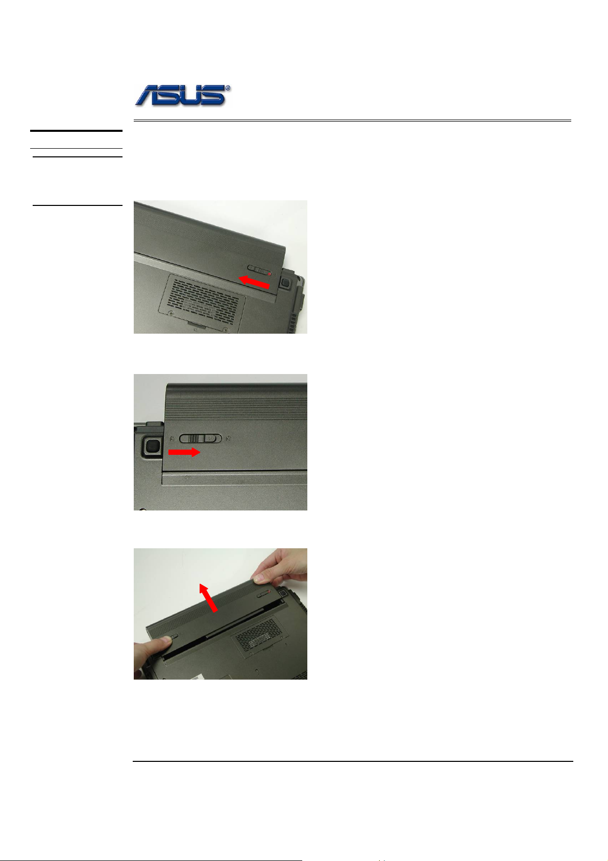
Battery Module
The illustration below shows how to remove the battery module.
1. Unlock and hold the latch No (1).
1
2. Slide the battery lock (No.2) and pull the battery pack out.
2
3. Pull the battery pack out.
2 - 2
Disassembly procedure
3
MEMORY
MODULE
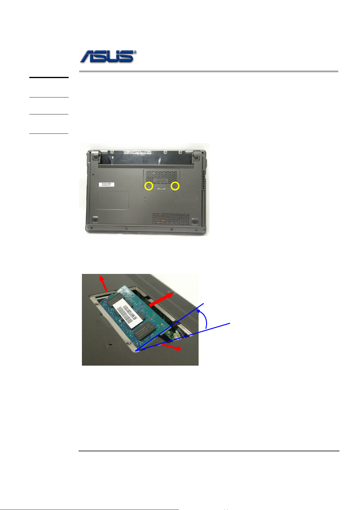
Memory Module
The S6Fm Series Notebook has 512 RAM onboard. There is one SO-DIMM sockets
for installing SO-DIMM RAM. It can upgrade the total memory size up to 1GB.
MEMORY
REMOVAL
Removing Memory module
1. Remove 2 screws (M2*3L (K)) and remove the DIMM cover.
M2*3L
2. Open the 2 latches aside (No. 1, 2), which will pop the memory module up to an
angle of 30°, then pull out the memory module in that angle (No. 3).
1
30o
2
2 - 3
Disassembly procedure
OPTICAL
DRIVE
DEVICE
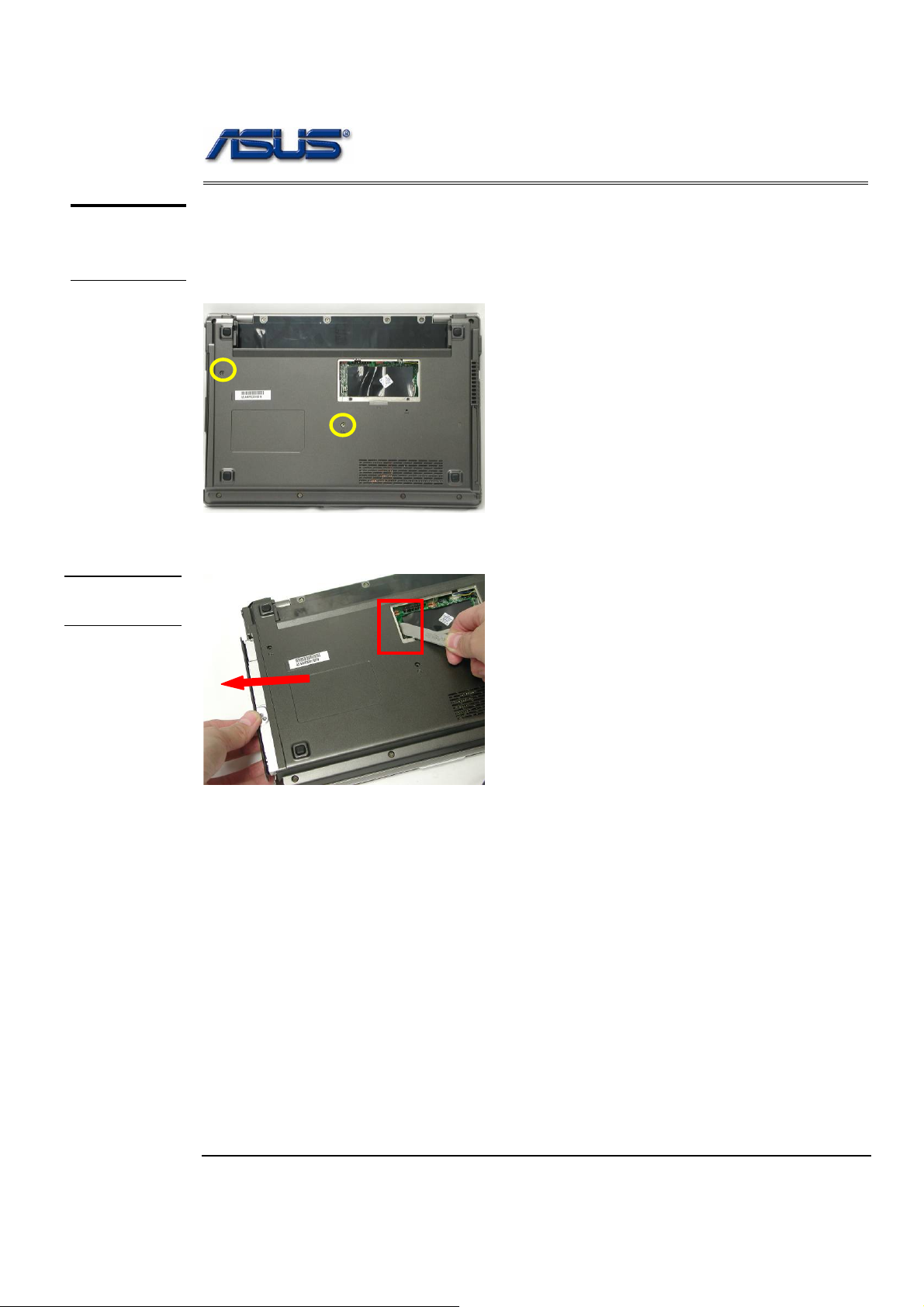
ODD Module
The illustration below shows how to remove the ODD module.
1. Remove 2 screws (M2*4L (K)).
M2*4L
2. Push the ODD Module out by a pair of tweezers.
ODD
REMOVAL
2 - 4
Disassembly procedure
KEYBOARD
K/B REMOVAL
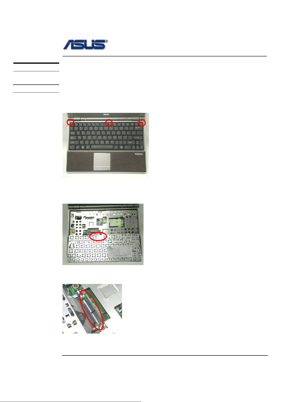
Keyboard
The illustration of below shows how to remove the keyboard.
Removing Keyboard
1. Push the 3 latches in (No.1, No.2, No.3) with a pair of tweezers or a single-slotted
screwdriver and lift the keyboard plate up.
1 2 3
2. Lay the keyboard down over the Touch Pad module. *Do not remove the
keyboard yet. The keyboard cable is still attached.
3. Disconnect the FPC connector by a pair of tweezers.
2 - 5
CABLE
REMOVAL
Disassembly procedure
Removing Keyboard Cable
1. Use a flexible connector tool to unlock the cable connector on both ends (no. 1).
2. Carefully pull out the keyboard cable (no. 2) with a pair of tweezers.
3. Lock the connector (no. 3) again to avoid possible breakage.
2. Cable out
TOP CASE
MODULE
1. Unlock
3.
1. Unlock
3.
4. Remove keyboard from the top case.
T op Case Module
The illustrations below show how to disassemble and remove the top case module of the notebook.
The module contains the top case itself.
Removing top Case Module
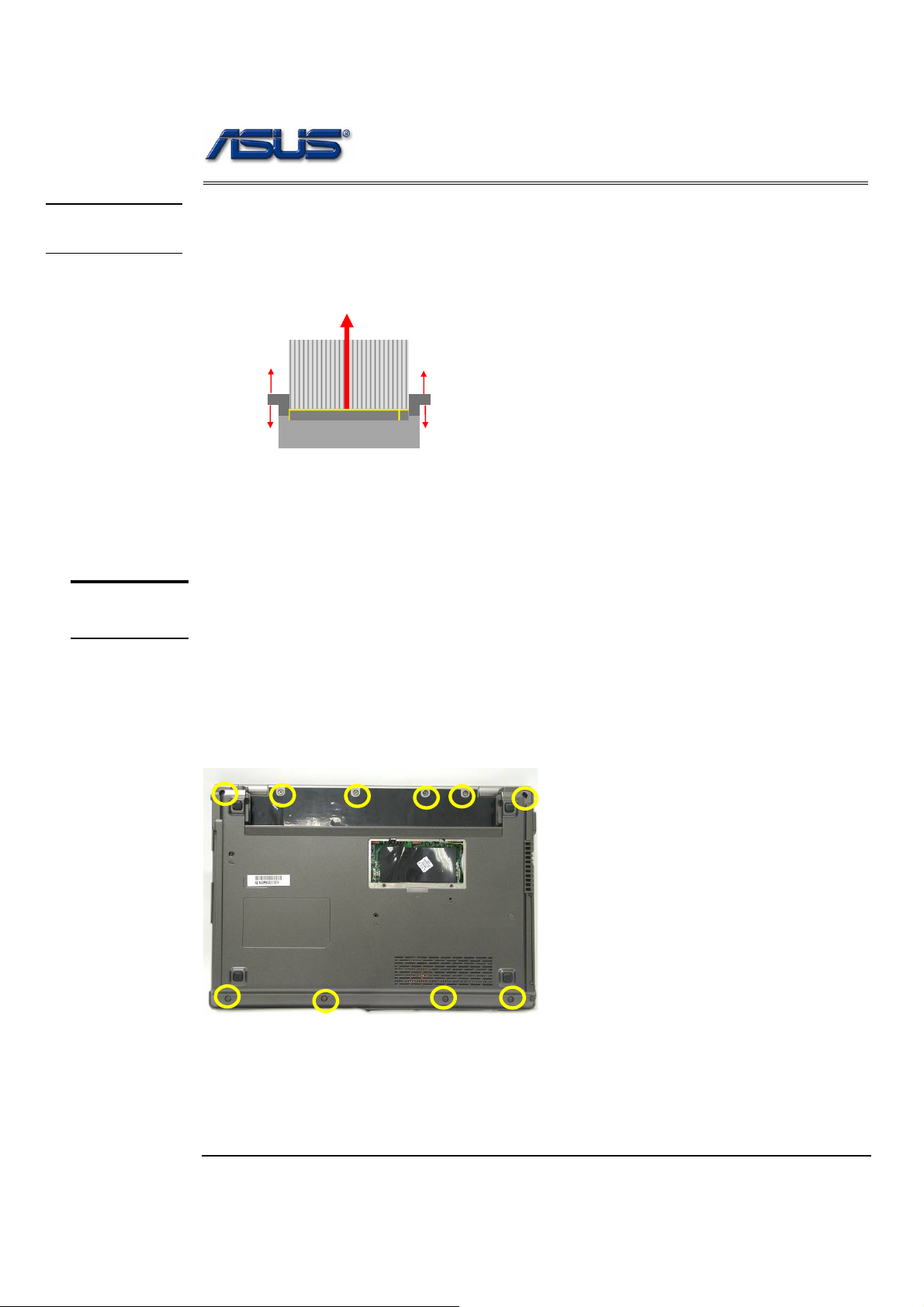
1. Remove 10 screws (M2*8L(K)) on the bottom case.
M2.5*8L
2 - 6

Disassembly procedure
2. Disconnect all cables & FPC on Top case.
Bluetooth cable
Mic cable
LED FBC
Gear cable
Touchpa d FBC
3. Remove 7 screws (M2*8L (K)) & 1 screws (M2*13L (K)) & 3 screws (M2*4L (K)) on
the bottom case.
M2*8L
M2*4L
M2*13L
4. Take away the top case from the bottom case.
2 - 7

TOP CASE
REMOVAL
Disassembly procedure
Top Case Module
5. Take away the LED & Bluetooth & Gear boards & MIC module on the top case.
LED board BT board
Gear board
MIC module
Touchpad bottom board
6. Remove 2 screws (M2*3L(K)) on the LED board and take away the L ED board.
7. Disconnect the LED FFC.
M2*3L
8. Take away the Bluetooth board and disconnect the Bluetooth cable.
2 - 8

Disassembly procedure
9. Take away the MIC module from the top case.
10. Remove 1 piece of tape and 1 screw (M2*3L(K)) on the Gear board then take away
the Gear board from the Top case.
11. Disconnect the Gear board cable.
M2*3L
12. Tear off 1 piece of tape and disconnect 2 FFC on Touchpad bottom board.
FFC cable
2 - 9

Disassembly procedure
13. Remove 4 screws (M2*3L(K)) and take away the Touchpad bottom board from the
Top case.
M2*3L
WALN
MODULE
WALN
REMOVAL
WALN Module
The illustrations below show how to remove the WALN module from the notebook.
Removing WALN Module
1. Tear off 1 piece of tape and disconnect 2 antenna cables.
2. Remove the Wireless LAN module by opening 2 latches aside, and pull it out.
2 - 10

Disassembly procedure
MOTHER
BOARD
MOTHERB
OARD
REMOVAL
Motherboard
The illustrations below show how to disassemble and remove the Motherboard.
Removing Motherboard
1. Tear off 2 pieces of tapes.
2. Disconnect coaxial & inverter & speaker cables.
Coaxial ca ble
Speaker cable
Inverter cable
3. Arrange all cables and remove 4 screws (M2*5L (K)) on both hinge.
M2*5L M2*5L
2 - 11

Disassembly procedure
4. Separate the LCD module from bottom case.
5. Disconnect the IO FPC and cable.
IO FPC
IO
MB
Board
IO cable
2 - 12

Disassembly procedure
6. Remove 1 screw (M2*5L (K)) on the IO board.
7. Remove the IO board from the bottom case.
8. Remove 3 screws (M2*5L (K)) on the MB.
M2*5L
2 - 13

Disassembly procedure
9. Remove the MB from the bottom case.
HDD
MODULE
HDD Module
The illustrations below show how to remove the HDD module from the notebook.
HDD
MODULE
REMOVAL
Removing HDD Module
1. Remove 2 screws (M3*6L (K)) on the MB and turn over the MB.
M3*6L
2. Tear off 1 piece of tape on the HDD FPC.
2 - 14

Disassembly procedure
3. Disconnect the HDD FPC and take away the HDD module from MB.
4. Disconnect the HDD FPC.
5. Remove 2 screws (M3*3L (K)) and take away the HDD bracket.
M3*3L
2 - 15

Disassembly procedure
CPU FAN
MODULE
CPU FAN
REMOVAL
CPU FAN Module
The illustrations below show how to remove the CPU FAN module from the notebook.
Removing CPU FAN Module
1. Remove 4 screws (M2.5*5L (K)) and disconnect the CPU Fan cable then remove
the FAN module.
M2.5*5L
2. Tear off 1 piece of tape.
3. Remove 2 screws (M2*3L (K)) and disconnect the modem cable then remove the
modem module.
CPU
Memory
M2*3L
2 - 16

Disassembly procedure
LCD MODULE
LCD MODULE
DISASSEMBLY
LCD Module
The illustrations below show how to remove and disassemble the LCD module. The
module contains LCD panel, Inverter board, LCD bezel, LCD back cover.
Disassembling LCD Module
1. Remove 3 rubber pads and 3 screws (M2 x 3L) from LCD module.
2. Prying the inside edges of the LCD bezel, and then separates it from LCD back
cover.
M2*3L
3. Tear off 1 piece of tape.
.
4. Disconnect 2 cables and remove 1 screw (M2 *2.3L (K)) then take away the
inverter board.
M2*2.3L
2 - 17

Disassembly procedure
5. Remove 2 screws (M2 *3L (K)) & 2 screws (M2*4L (K)) then take away the LCD
panel from the LCD back cover.
M2*3L
M2*4L
6. Remove 1 piece of tape and disconnect the coaxial cable.
7. Remove 2 piece of tapes and 4 screws (M2 *2.5L (K)) on the speaker module
then take them away.
M2*2.5L
2 - 18

Disassembly procedure
8. Remove 4 screws (M2 *2L (K)) on both hinge and take both hinge away.
2 - 19
 Loading...