


Assembly procedure
A
Chapter
Assembly Procedure
Please follow the information provided in this section to perform the complete
assembly procedure of the notebook. Be sure to use proper tools described
before.
fter you have completed the previous chapter of complete disassembly, please follow this
chapter to assemble the notebook back together. This chapter describes the procedures
of the complete notebook assembly. In addition, in between procedures, the detailed
assembly procedure of individual modules will be provided for your service needs.
The assembly procedure consists of the following steps:
• LCD Module
• CPU FAN Module
• HDD Module
• Motherboard
• WLAN module
• Top Case Module
• Keyboard
• ODD Module
• Memory Module
• Battery Module
3 - 1
Assembly procedure
LCD MODULE
LCD
MODULE
ASSEMBLY
LCD Module
The illustrations below show how to assemble and install the LCD module of the
notebook.
I
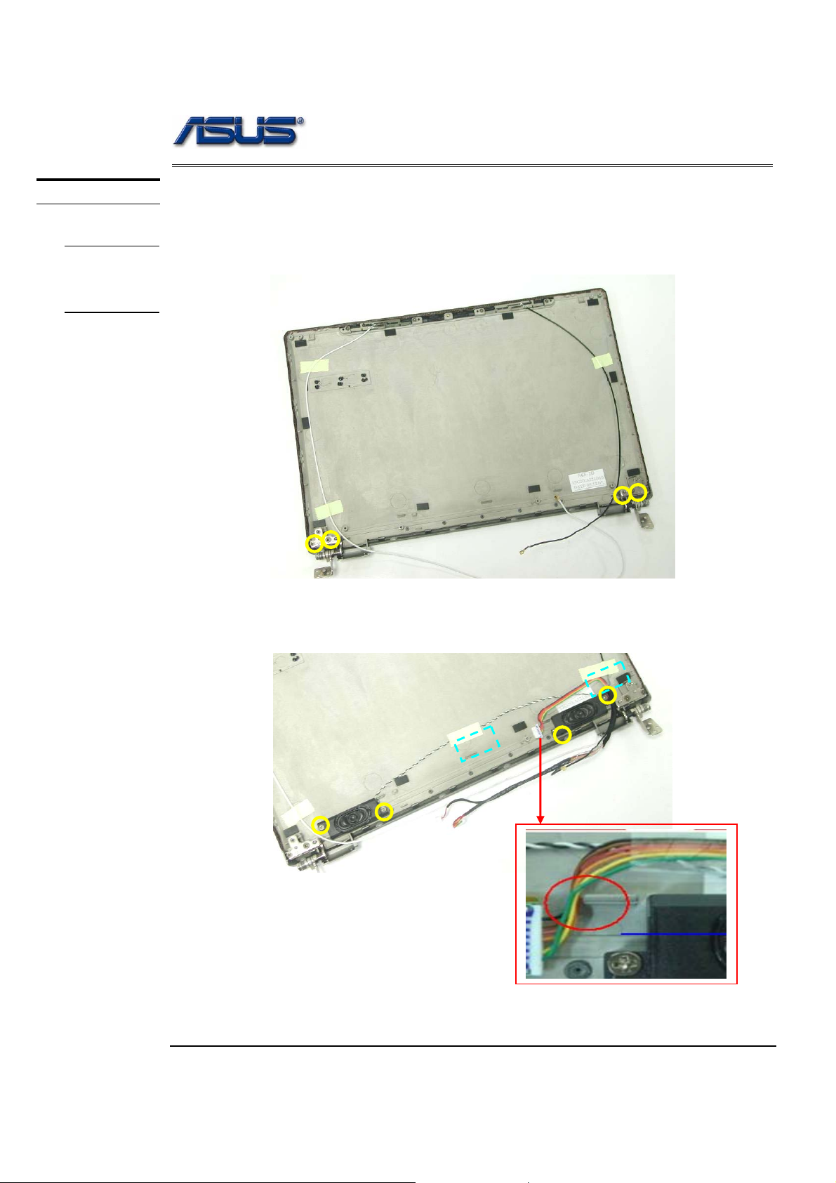
1. Inser the both hinge and secure 4 screws (M2 *2L (K)) on the LCD back cover.
M2*2L
2. Inster the speaker module and secure 2 piece of tapes and 4 screws (M2 *2.5L (K))
to secure it.
M2*2.5L
Arrange the cable at the left side of the hook.
3 - 2
Assembly procedure
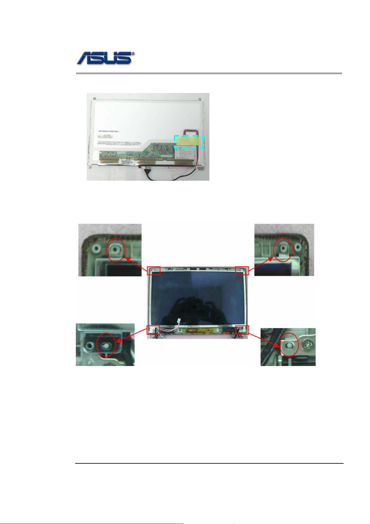
3. Connect the coaxial cable and paste 1 piece of tape.
Assembly LCD Module
1. Put LCD panel in correct position, and assemble into LCD Back cover.
3 - 3
Assembly procedure
2. Secure 2 screws (M2 *2L (K)) & 2 screws (M2.5*4L (K)) to secure it.
M2*2L
M2.5*4L
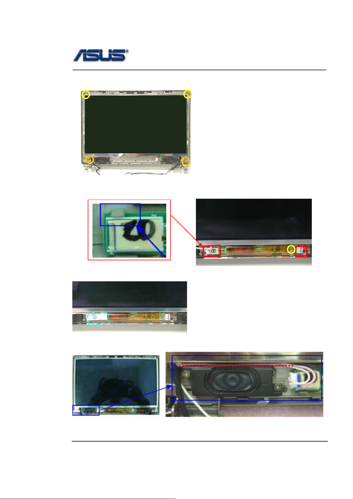
3. Inserter the inverter board into to the right po sition and se cure 1 scre w (M2 *2L (K))
to secure it.
The right position
M2*2.3L
at the hook
4. Paste 1 piece of tape on the inverter board.
5. Arrange the LCD power cable between LCD panel and speaker.
3 - 4
Assembly procedure
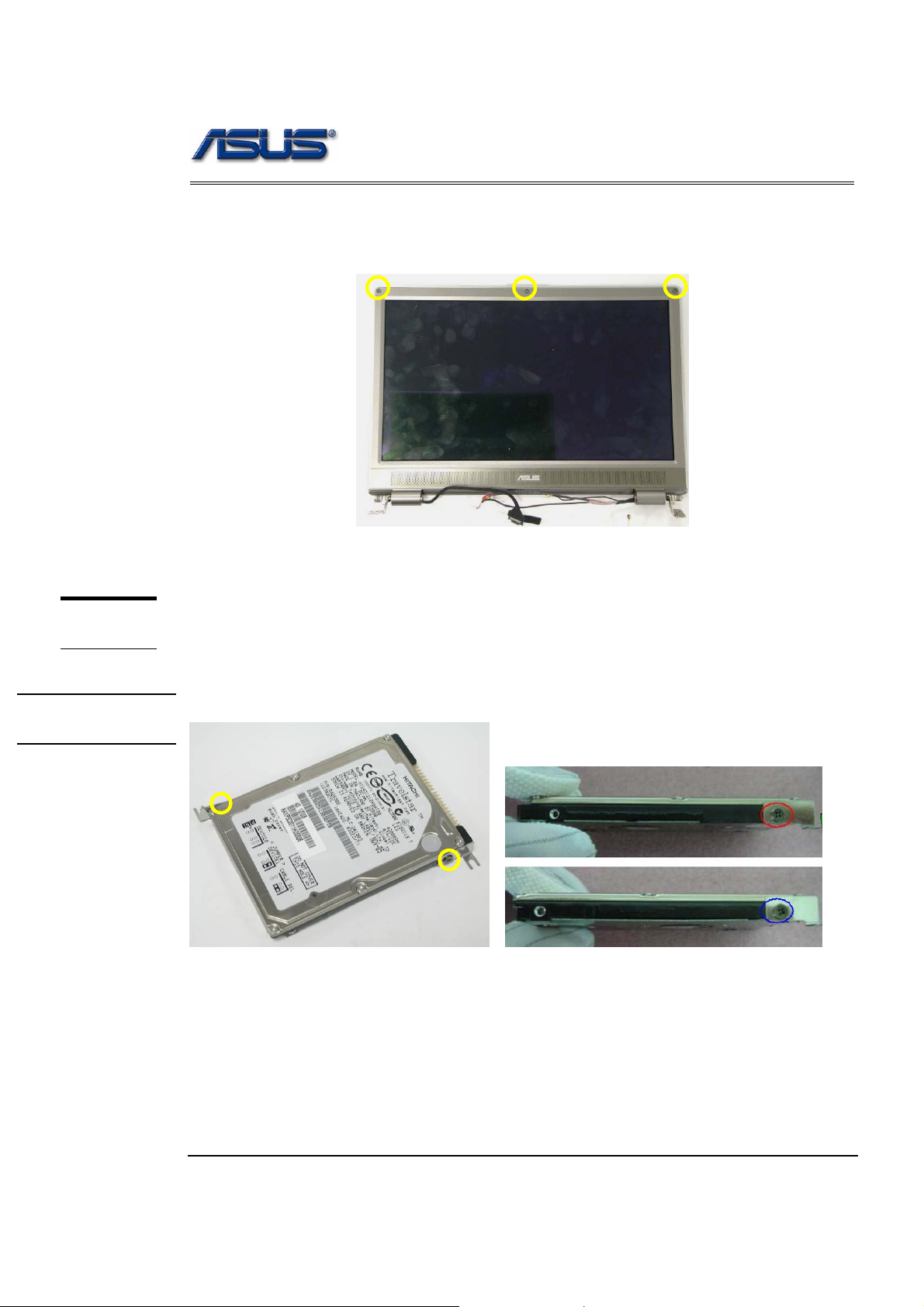
6. Combine the LCD bezel and LCD Cover properly and press on all four edges until
them snap into position.
7. secure 3 screws (M2.5 x 7L) and 3 rubber pads on LCD module.
M2*3L
HDD
MODULE
HDD
INSTALLATION
HDD Module
The illustrations below show how to assemble and install the HDD module of the
notebook
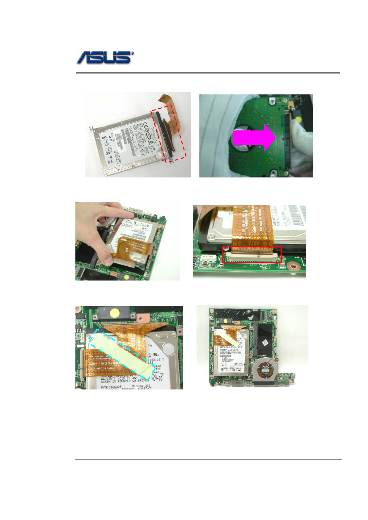
1. Secure 2 screws (M3*3L (K)) to fix HDD into HDD bracket.
M3*3L
3 - 5
Assembly procedure
2. Connect the HDD FPC.
3. Install the HDD module into the MB and connect the HDD FPC to secure it.
4. Paste1 piece of tape on the HDD FPC.
3 - 6
Assembly procedure
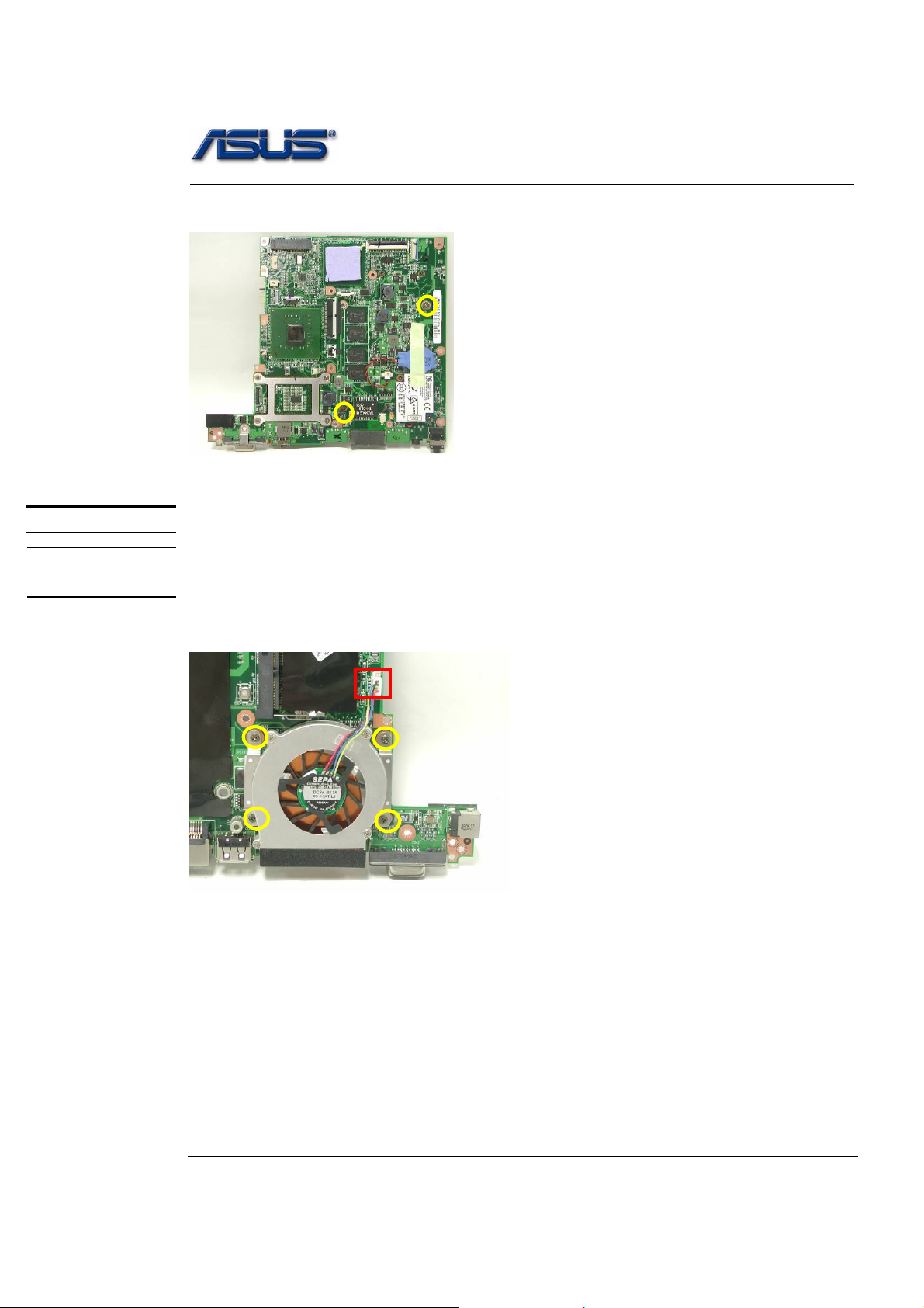
5. Turn over the MB and secure 2 screws (M2.5*5L (K)) to secure the HDD module.
M2.5*5L
CPU MODULE
CPU
INSTALLATION
CPU Module Assembly
The illustration below shows how to install CPU and the CPU heat sink of the notebook.
1. Install the FAN module and secure 4 screws (M2.5*5L (K)) and connect the CPU
Fan cable to secure it.
M2.5*5L
3 - 7

MOTHERBOARD
MOTHERBOARD
ASSEMBLY
Assembly procedure
Motherboard
The illustrations below show how to assemble and install the motherboard of the
notebook.
1. Install the modem board and secure 2 screws (M2.5*5L (K)).
2. Connect the modem cable and paste 1 piece of tape.
M2*3L
CPU
Memory
3. Assemble MB into Bottom case, and notify that the switch parts of MB should be
assembled well with the WLAN switch button of bottom case.
3 - 8

Assembly procedure
4. Secure 3 screws (M2*5L (K)) to secure the MB.
M2*5L
5. Install the IO board into the bottom case.
6. The IO board must be the right position.
f
3 - 9

Assembly procedure
I
7. Secure 1 screw (M2*5L (K)) to secure the IO board.
M2*5L
8. Insert the IO FPC & cable into the MB and press well.
IO
MB
Board
Confirm the FPC is
curved upward
IO FPC
When opening and closing the
Latch, should force the two ends
of Latch at the same time ends of
the Latch damaged.
3 - 10

TOP CASE
MODULE
TOP CASE
MODULE
ASSEMBLY
Assembly procedure
T op Case Module
The illustrations below show how to assemble and install the top case module of the
notebook.
1. Combine the Top case module and LCD module.
2. Secure 4 screws (M2*5L (K)) to fix the hinge.
M2*5L
M2*5L
3. Arrange the Antenna-White into the hook of the bottom case. Notify the cable
should be straight, don’t hang down.
3 - 11

Assembly procedure
4. Arrange all cables and paste 1 piece of tape to fix them.
Don’t across
the hole.
5. Connect coaxial & inverter & speaker cables.
6. Paste 1 piece of tape.
Coaxial cable
Speaker cable
Inverter cable
3 - 12

Assembly procedure
WALN
MODULE
WALN
INSTALLATION
Assembling WLAN Module
The illustrations below show how to assemble and install the WALN module to the
notebook.
1. Insert the WALN module into the WALN socket by an angle of 30 degree, and push
down to latch.
2. Connect 2 antenna cables and paste 1 piece of tape.
TOP CASE
ASSEMBLE
Top Case Module
1. Insert the Touchpad bottom board into the right position and secure 4 screws
(M2*3L(K)) to secure it.
3 - 13

Assembly procedure
2. Disconnect 2 FFC cables on Touchpad bottom board.
FPC
3. Connect the Gear board cable and insert the Gear board to the right position.
4. Secure 1 screw (M2*3L(K)) and paste 1 piece of tape on the Gear bo ard
M2*3L
3 - 14

Assembly procedure
5. Insert the MIC module on the top case and paste 1 piece of tape to secure it.
6. Connect the Bluetooth cable and insert the Bluetooth board to the top case.
7. Connect the LED FFC.
8. Insert the LED board and secure 2 screws (M2*3L(K)) on the top case.
M2*3L
3 - 15

Assembly procedure
Assembling top Case Module
9. Combine the top case and LCD module.
10. Secure 7 screws (M2*8L (K)) & 1 screws (M2*13L (K)) & 3 screws (M2*4L (K)) on
the bottom case.
M2*8L
M2*4L
M2*13L
3 - 16

Assembly procedure
11. Connect all cable & FBC on the Top case.
Bluetooth cable
MIC cable
Coaxial FBC
Gear cable
Touchpa d FBC
12. Secure 10 screws (M2*8L(K)) on the bottom case.
M2.5*8L
3 - 17

Assembly procedure
KEYBOARD
KEYBOARD
ASSEMBLY
Assembling Keyboard
The illustrations below show how to assemble and install the Keyboard of the notebook.
1. Place the Keyboard module on front side of the bottom case. Then connect
Keyboard FPC Cable w ith a pair of twee zers .
2. Install Keyboard properly and note the lower side should inset first. Push the 3
latches to fix the keyboard.
1 2
3
3 - 18

Assembly procedure
ODD MODULE
ODD MODULE
INSTALLATION
ODD Module
The illustrations below show how to assemble and install the ODD Module of the
notebook.
1. Install the ODD Chassis.
2. Secure 2 screws (M2*4L (K)) to fix it.
M2*4L
3 - 19

Assembly procedure
MEMORY
MODULE
MEMORY
INSTALLATION
Assembling Memory Module
The illustrations below show how to assemble and install the memory module to the
notebook.
1. I nsert the Memory module into the memory socket by an angle of 30 degree, and
push down to latch the memory module.
30o
2. Insert the DIMM cover and secure 2 screws (M2*3L (K)) to fix it.
M2*3L
3 - 20

Assembly procedure
BATTERY
MODULE
BATTERY
INSTALLATION
Battery Module
The illustrations below show how to install battery module of the notebook.
1. Install the battery module. Slide the battery latch to close t he battery lock.
3 - 21
 Loading...