

Page 1

Disassembly procedure
Chapter
Disassembly Procedure
Please follow the information provided in this section to perform the complete
disassembly procedure of the notebook. Be sure to use proper tools described
before.
37E Notebook consists of various modules. This chapter describes the procedures for the
complete notebook disassembly. In addition, in between procedures, the detailed
S
The disassembly procedure consists of the following steps:
• Battery Module
• CPU Module
• Memory Module
• WLAN Module
• HDD Module
• Optical Drive Module
• Keyboard Module
• Top Case Module
• Motherboard Module
• LCD Module
disassembly procedure of individual modules will be provided for your service needs.
2 - 1
Page 2
Disassembly procedure
BATTERY
Battery Module
The illustration below shows how to remo ve the battery m odule.
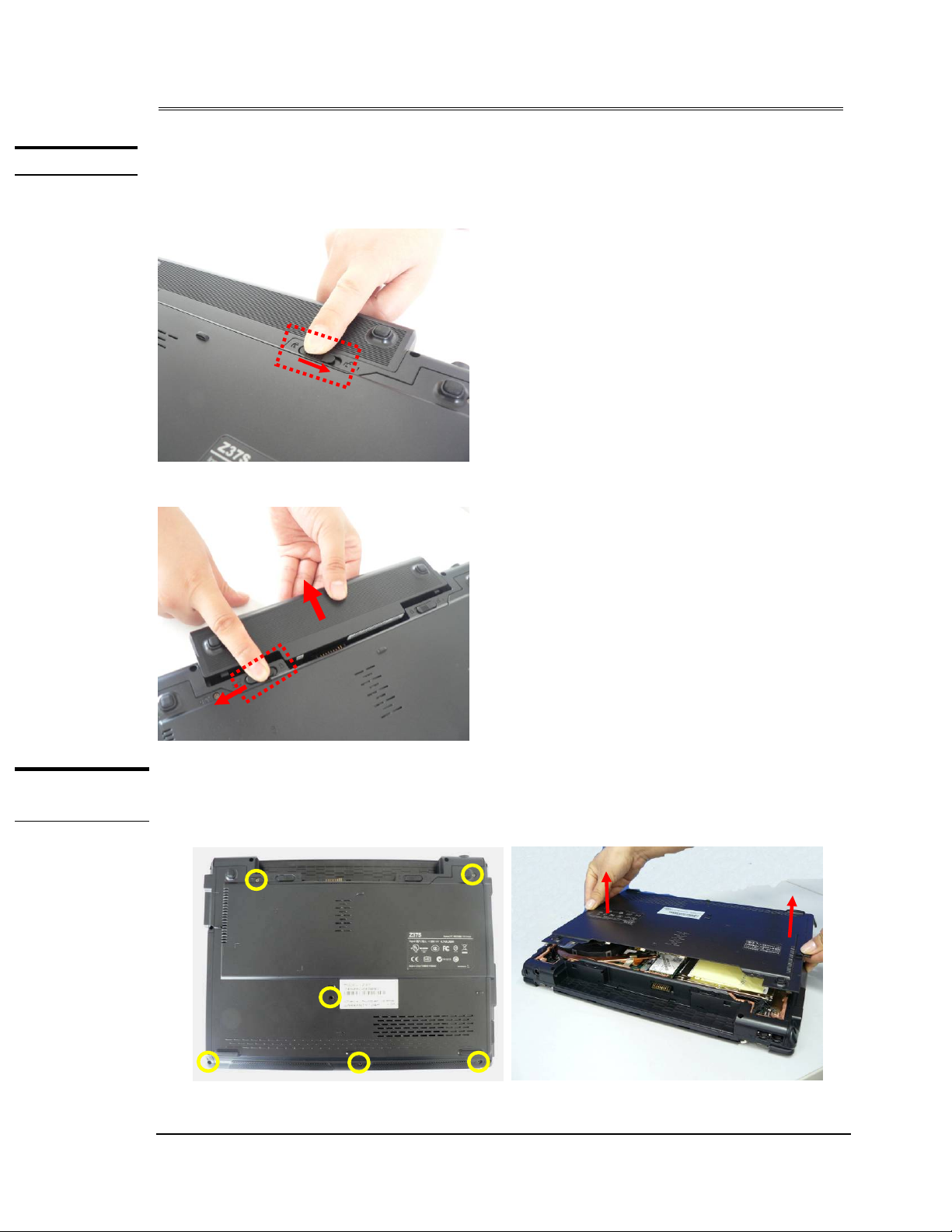
Remove Battery module
1.Slide the battery latch 1 to open battery lock
2.Slide the battery latch 2 and pull the whole battery out.
CPU MODULE
REMOVAL
CPU Module
The illustrations below show how to remo ve the CPU modul e from the notebo ok.
Removing CPU module
1. Remove 6 screws on CPU door and take the CPU door away.
2 - 2
Page 3
Disassembly procedure
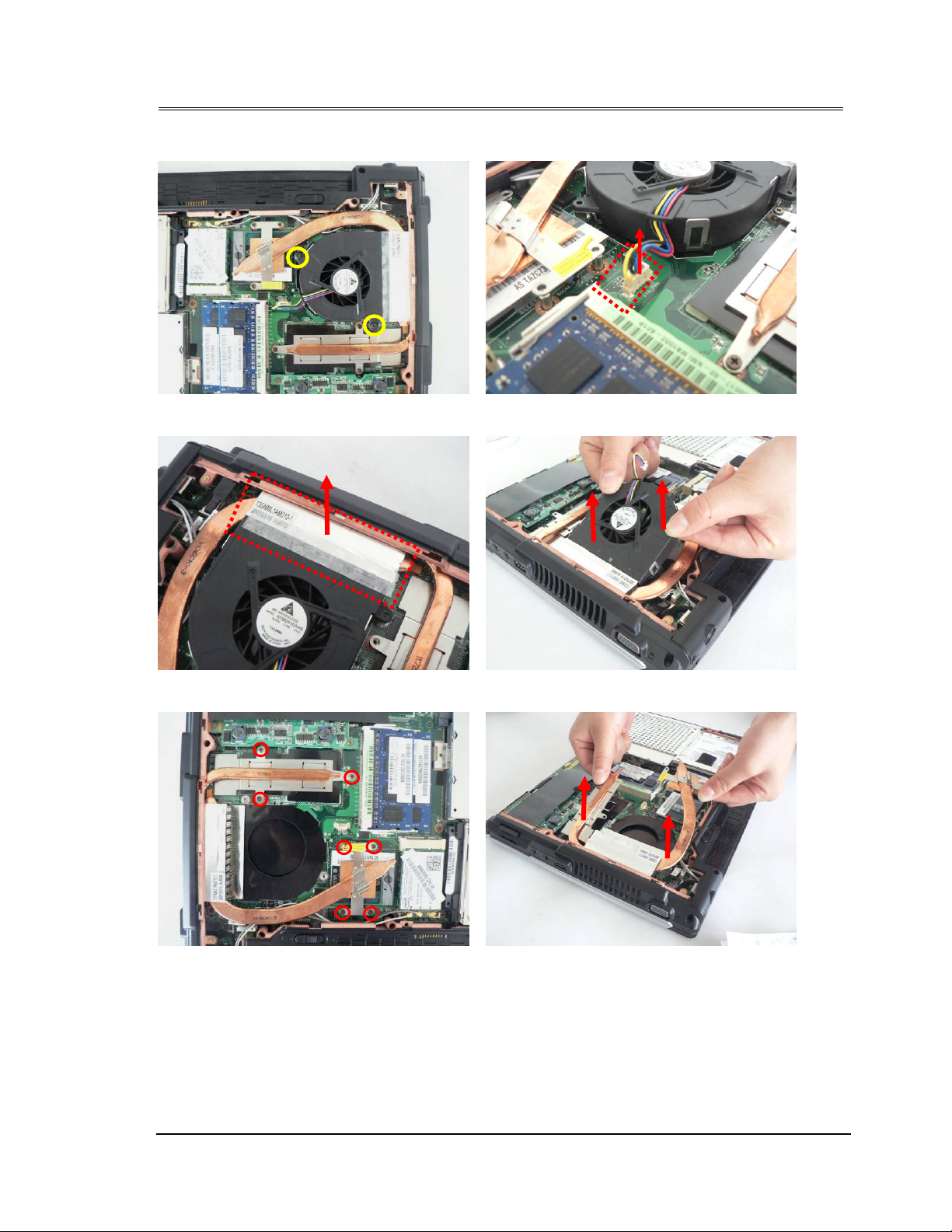
2. Remove 2 screws and then disconnect the CPU fan cable.
3. Remove 1 piece of tape here and take away the CPU fan from the system.
4. Remove 7 screws on heat sink and take away the heat sink module.
2 - 3
Page 4
Disassembly procedure
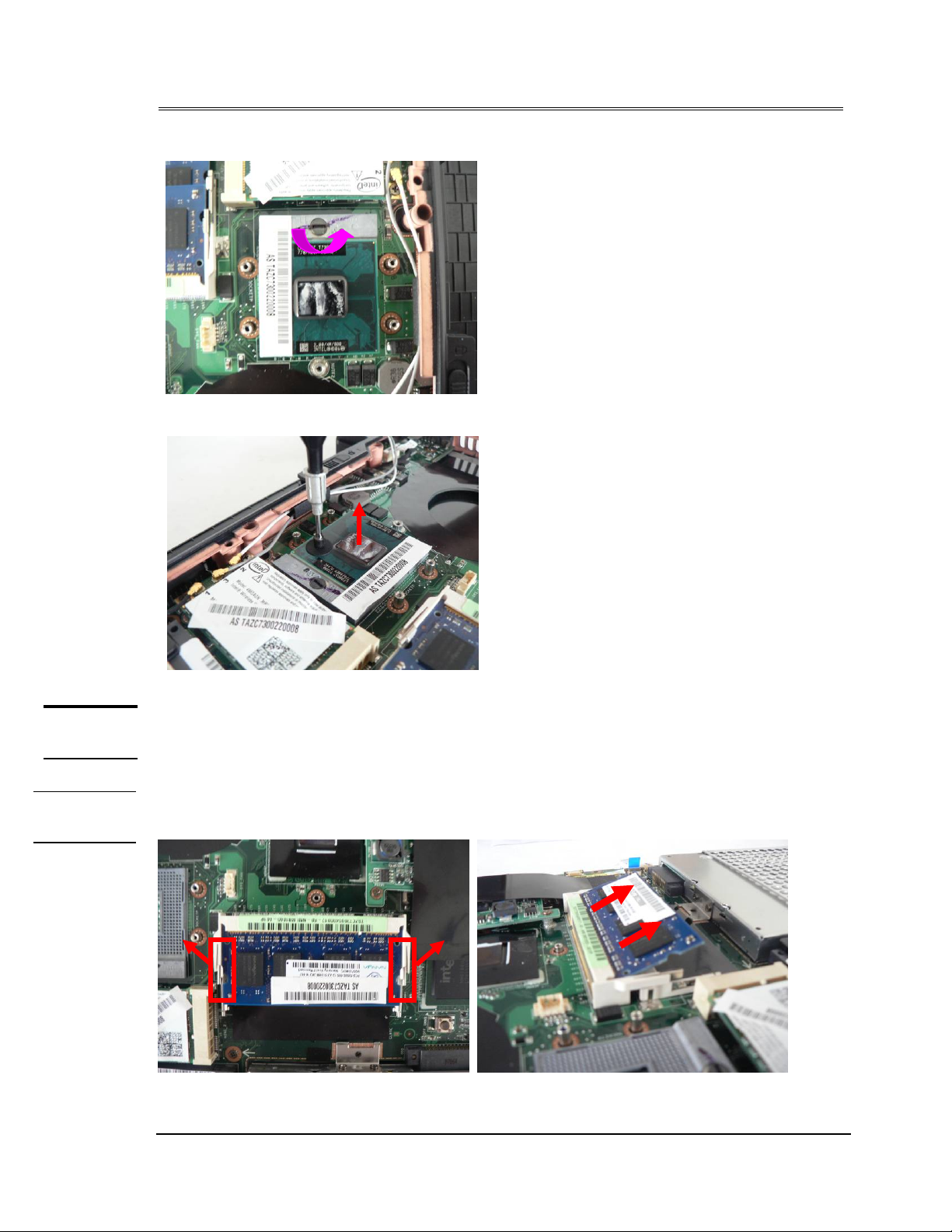
5. Turn the non-removable screw here 180 degrees counter-clockwise to loosen the CPU.
6. Squeeze the vacuum handling pump on the CPU and use it to lift the CPU away.
MEMORY
MODULE
MEMORY
REMOVAL
Memory Module
The illustration shows how to remove the memory modu le form the notebo ok.
Removing Memory module
1. Pull two latches here to pop the Memory module up at 45° angles, and then pull out the
module at that angle.
2 - 4
Page 5
Disassembly procedure
WLAN
MODULE
WLAN
MODULE
REMOVAL
WLAN Module
The illustration below shows how to remo ve the WLAN m odule from the note book.
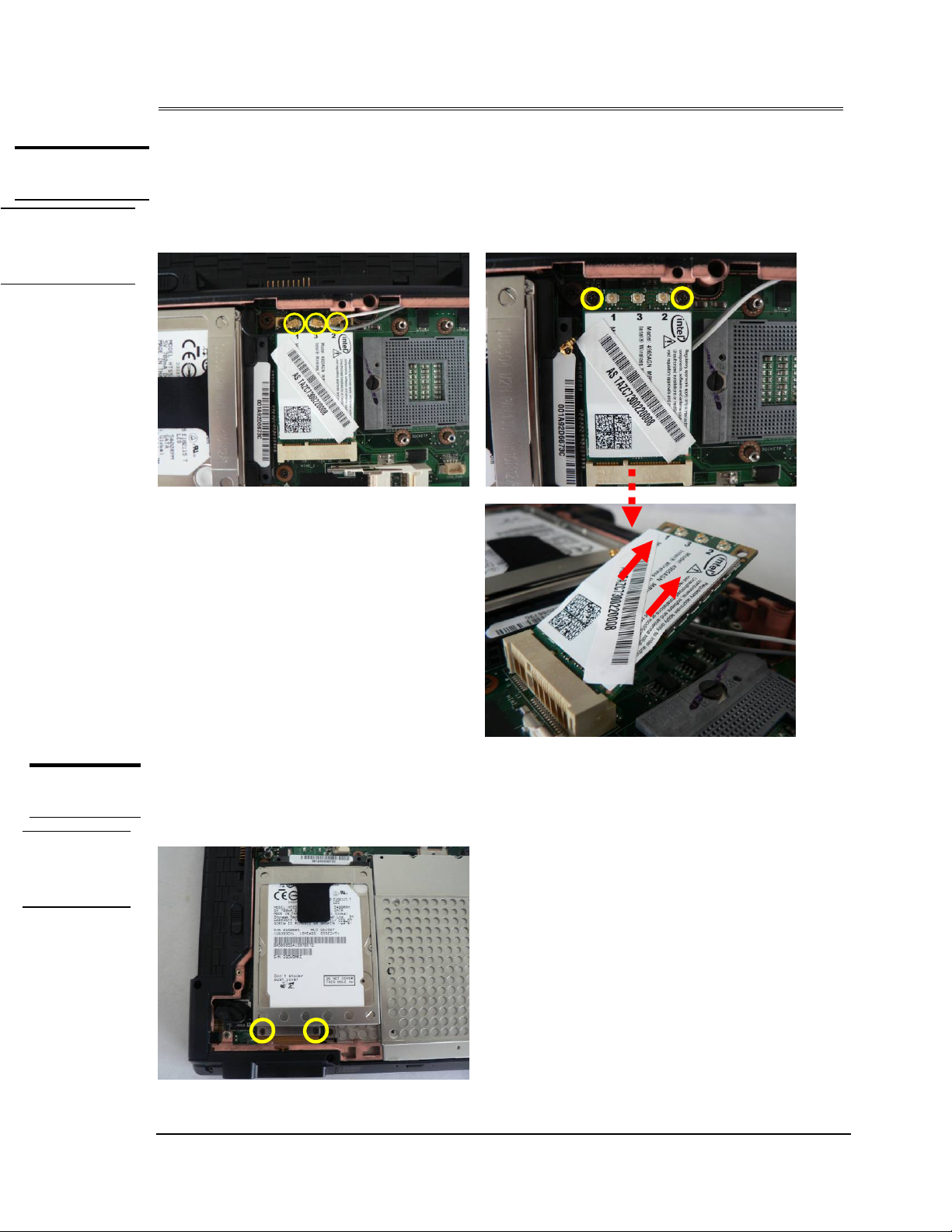
Remove WLAN module
1. Disconnect the three antennas here and then remove two screws to pop it up at 45 degree
angles and then pull it out at that angle.
HDD
MODULE
HDD
MODULE
REMOVAL
HDD Module
The illustrations below show how to remove the HDD module from the notebook.
Removing HDD Module
1. Remove 2 screws here.
2 - 5
Page 6

Disassembly procedure
2. Pull the hard disk module toward the direction of the arrow and then lift it up and take it
out.
3. Remove 4 screws to separate HDD from HDD housing.
2 - 6
Page 7
Disassembly procedure
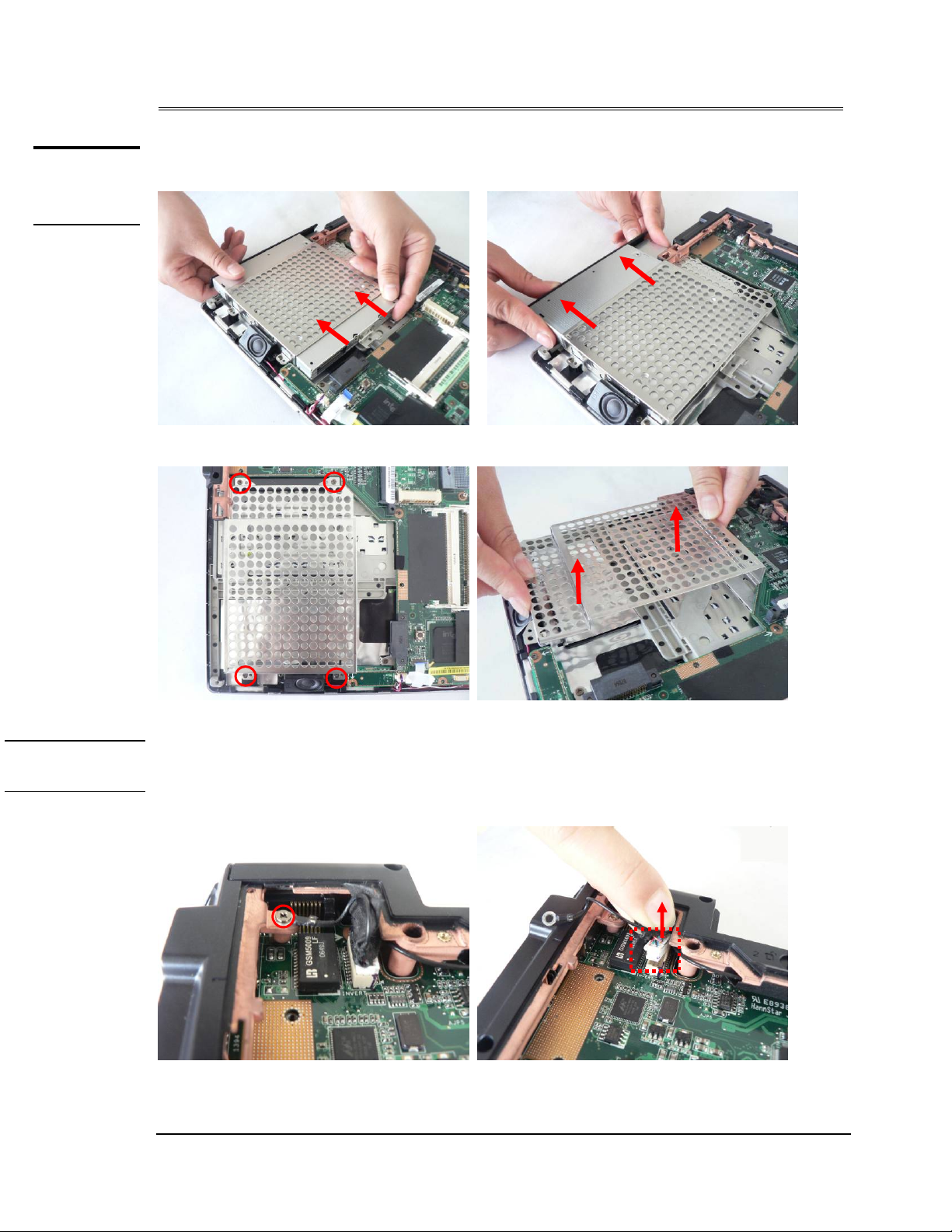
OPTICAL
DRIVE
REMOVAL
Optical Drive Module
1. Push the ODD module softly and slowly pull the ODD module out.
2. Remove 4 screws here and remove the ODD bracket.
BOTTOM CASE
REMOVAL
Bottom Case Module
The illustrations below show how to disassemble a nd remove th e bottom case mod ule of the notebook.
The module contains the bottom case itself.
1. Remove 1 screw here and disconnect the cable.
2 - 7
Page 8

Disassembly procedure
2. Put the WLAN antennas through the hole of bottom case.
3. Disconnect the two cables here.
4. Remove 10 screws here on bottom case.
2 - 8
Page 9

Disassembly procedure
5. Remove the left side cover, right side cover and the bottom case orderly.
2 - 9
Page 10

Disassembly procedure
KEYBOAR
Keyboard Module
The illustrations below show how to remove the keyboard.
Removing Keyboard
1. Open 4 latches (Esc, F5, F10 and Pause) on keyboard module.
2. Turn over the keyboard plate and disconnect the keyboard FPC, and then remove the
keyboard plate.
2 - 10
Page 11

Disassembly procedure
Removing Keyboard Cable
1. Use a flexible connector tool to unlock the cable connector on both ends (no. 1).
2. Carefully pull out the keyboard cable (no. 2) with a pair of tweezers.
3. Lock the connector (no. 3) again to avoid possible breakage.
2. Cable out
THERBOARD
MODULE
1. Unlock
3.
1. Unlock
3.
Motherboard module
The illustrations below show how to disassemble and remove the Motherboard
module
1. Tear this mylar here and remove 5 screws here.
2. Remove the Card Board module.
2 - 11
Page 12

Disassembly procedure
3. Remove both hinge covers and remove 2 screws on each hinge.
4. Put the cables and antennas through the hinge holes.
2 - 12
Page 13

Disassembly procedure
5. Take the LCD module away.
6. Tear 1 piece of tape here, and then disconnect the fingerprint FPC and speaker cable from
mother board.
Fingerprint FPC
Touchpad cable
7. Remove 7 screws here on mother board and then remove the mother board.
2 - 13
Page 14

Disassembly procedure
8. Remove the TPM board.
9. Remove 6 pieces of tape here and then disconnect the modem cable from mother board.
10. Remove 2 screws here and remove the modem module.
2 - 14
Page 15

Disassembly procedure
TOP CASE
REMOVAL
T op Case Module
The illustrations below show how to disassemble a nd remove th e top case module of the notebook.
The module contains the top case itself.
Removing Top Case Module
1. Tear 1 piece of tape here and remove the Bluetooth module.
2. Remove 2 screws on each speaker.
3. Take the speaker lines out of the slot and then remove the speaker module.
2 - 15
Page 16

Disassembly procedure
4. Remove this black Mylar here and disconnect the fingerprint FPC and touchpad FPC here.
5. Remove 4 screws on fingerprint bracket and take it away.
6. Remove 2 screws here to separate the fingerprint bracket from the fingerprint board.
2 - 16
Page 17

Disassembly procedure
LCD MODULE
CD MODULE
ISASSEMBLY
LCD Module
The illustrations below show how to remove and disassemble the LCD module. The
module contains LCD panel, Inverter board, LCD bezel, LCD back cover.
Disassembling LCD Module
1. Remove 6 rubber pads and 6 screws on LCD front bezel.
2. Pry the inside edges softly to separate LCD front bezel from LCD panel and take it away .
3. Remove 2 screws here.
2 - 17
Page 18

Disassembly procedure
4. Disconnect the LCD cable and inverter cable from inverter board, and then take it away.
5. Remove 4 screws here.
2 - 18
Page 19

Disassembly procedure
6. Take the LCD panel away.
7. Remove 3screws on each LCD bracket and take both brackets away.
8. Remove the white transparent Mylar here and disconnect Coaxial cable from LCD panel, and
then remove the coaxial cable.
2 - 19
Page 20

Disassembly procedure
9. Remove 2 screws on each hinge and take both hinges away.
10. Remove 1 screw here and tear 6 pieces of tape.
11. Take out the camera module and microphone module, and then remove them together.
2 - 20
Page 21

Disassembly procedure
12. Tear the tape and remove the black antenna.
13. Tear 9 pieces of tape and remove the white antenna and gray antenna.
1 1 2
5
3 4
2 - 21
 Loading...