

Page 1

S370-DL
®
CPU Card
Installation Guide
E593
Page 2

ASUS Technical Support Information
ASUSTeK COMPUTER INC. (Asia-Pacific)
MB/Accessories (Tel):+886-2-2890-7121 (English)
Fax: +886-2-2895-9254
Email: [email protected]
WWW: www.asus.com.tw
FTP: ftp.asus.com.tw/pub/ASUS
ASUS COMPUTER INTERNATIONAL (America)
FTP: ftp.asus.com/Pub/ASUS
ASUS COMPUTER GmbH (Europe)
Hotline: MB/Accessories: +49-2102-9599-0
Fax: +49-2102-9599-11
Email: www.asuscom.de/de/support (for online support)
WWW: www.asuscom.de
FTP: ftp.asuscom.de/pub/ASUSCOM
2 ASUS S370-DL Installation Guide
Page 3

Introduction
The ASUS S370-DL CPU card allows Slot 1 motherboards to accept socket
370 processors with Front Side Bus running at up to 133MHz. The S370DL CPU card supports single Coppermine/Celeron and dual Coppermine/
Celeron (PPGA only) processors to give Slot 1 motherboard owners an
inexpensive way to upgrade their Pentium II/III computers using lower
costing socket 370 processors. Since socket 370 processors are designed
on the Pentium II/III design, the only difference is the package form factor. Additionally, the S370-DL CPU card can acquire temperature data
from the processor’s thermal diode and send it to the motherboard that
supports CPU thermal monitoring.
The following page displays a picture of the ASUS S370-DL CPU card with
black plastic retainers attached to the edges. The retainers are used to hold
the ASUS S370-DL CPU card in place using the motherboard’s Slot 1 retention mechanisms.
ASUS S370-DL Installation Guide 3
Page 4
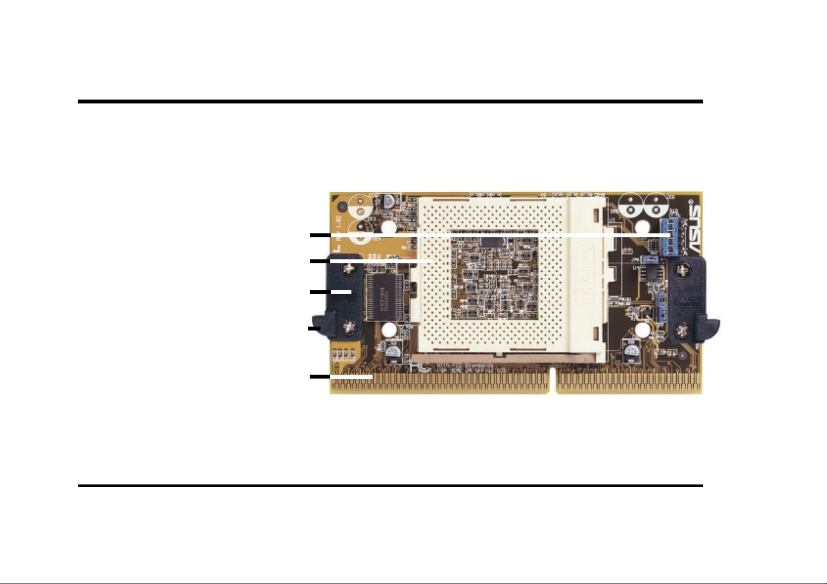
S370-DL CPU Card
ASUS S370-DL CPU Card
CPU Voltage Jumpers
Socket 370
Retainer
Fin
Slot 1 Compatible Connector
4 ASUS S370-DL Installation Guide
Page 5

Using the S370-DL CPU card
The general procedure for using the ASUS S370-DL CPU card:
1. Check the voltage setting for your socket 370 processor using the jumpers on the card if necessary. For current socket 370 processors, the default setting should be used.
2. Install the socket 370 processor . Lift the brown lever to 90° to install the
processor and lower the brown lever to lock the processor.
3. Install the CPU fan heatsink.
4. Mount the ASUS S370-DL CPU card over Slot 1 on the motherboard.
The two fins on the sides of the ASUS S370-DL CPU card must catch
on the retention mechanism so that it locks in place.
5. Connect the processor’s fan power connector to the motherboard.
Windows 98
6. Make sure that no wires or objects come in contact with the fan.
ASUS S370-DL Installation Guide 5
Page 6

Setting up the S370-DL CPU card
Setting the CPU voltage is not necessary for current socket 370 processors.
If required, your socket 370 processor should have its voltage requirement
printed on its surface or documentation. If no voltage is indicated or you are
not sure, use the “CPU Def.” setting as shown on the next page. Notice that
JP7 should be configured to distinguish between Coppermine and Celeron
processors.
WARNING! Exceeding your socket 370 processor’s required voltage
can damage your processor permanently! Make sure that the jumpers are
as shown for “CPU Def.” unless otherwise specified before powering on
your motherboard.
6 ASUS S370-DL Installation Guide
Page 7
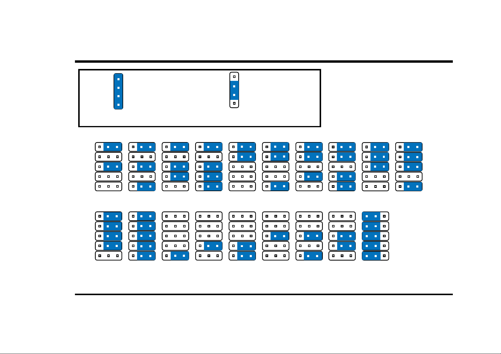
Setting up the S370-DL CPU card
4
3
2
JP7
Using Coppermine Processors
(Default)
1
123
123
123
JP5
JP4
JP3
JP2
JP1
1.50Volts
123
1.55Volts
123
1.60Volts
123
1.65Volts
JP5
JP4
JP3
JP2
JP1
2.00Volts
2.05Volts
2.10Volts
2.20Volts
Socket 370 CPU Voltage
4
3
2
JP7
Using Celeron Processors
123
123
1
123
1.70Volts
123
2.30Volts
123
1.75Volts
123
2.40Volts
123
1.80Volts
123
2.50Volts
123
1.85Volts
123
2.60Volts
123
1.90Volts
123
CPU Def.
(Default)
123
1.95Volts
ASUS S370-DL Installation Guide 7
Page 8

P/N 15-xxxxxxxxx
®
S370-DL CPU Card
 Loading...