

Page 1
RX3141
User’s Manual
Revision 1.01
Oct. 21, 2004
Page 2

Table of Contents
1
2
Introduction ..............................................1
1.1
Features................................................................................................................1
1.2
System Requirements..........................................................................................1
1.3
Using this Document ............................................................................................2
1.3.1
Notational conventions...............................................................................2
1.3.2
Typographical conventions........................................................................2
1.3.3
Special messages......................................................................................2
Getting to Know RX3141 .........................3
2.1
Parts List...............................................................................................................3
2.2
Hardware Features...............................................................................................3
2.3
Software Features................................................................................................3
2.3.1
NAT Features.............................................................................................3
2.3.2
Firewall Features........................................................................................4
2.3.2.1
Stateful Packet Inspection.............................................................4
2.3.2.2
Packet Filtering – ACL (Access Control List)................................4
2.3.2.3
Defense against DoS Attacks........................................................4
3
2.4.1.1
Application Level Gateway (ALG).................................................5
2.4.1.2
Log..................................................................................................5
2.4
Finding Your Way Around....................................................................................6
2.4.1
Front Panel.................................................................................................6
2.4.2
Rear Panel..................................................................................................7
2.4.3
Bottom View...............................................................................................8
2.5
Placement Options...............................................................................................9
2.5.1
Desktop Placement....................................................................................9
2.5.2
Magnet Mount Instructions.........................................................................9
2.5.3
Wall Mount Instructions:.............................................................................9
Quick Start Guide...................................11
3.1
Part 1 — Connecting the Hardware...................................................................11
3.1.1
Step 1. Connect an ADSL or a cable modem.........................................11
3.1.2
Step 2. Connect computers or a Network...............................................11
3.1.3
Step 3. Attach the AC adapter.................................................................12
3.1.4
Step 4. Power on RX3141, the ADSL or cable modem and power up
your computers.........................................................................................12
3.2
Part 2 — Configuring Your Computers..............................................................13
ii
Page 3

4
3.2.1
Before you begin......................................................................................13
3.2.2
Windows® XP PCs:.................................................................................13
3.2.3
Windows® 2000 PCs:..............................................................................13
3.2.4
Windows® 95, 98, and Me PCs ..............................................................14
3.2.5
Windows® NT 4.0 workstations:..............................................................15
3.2.6
Assigning static IP addresses to your PCs .............................................15
3.3
Part 3 — Quick Configuration of the RX3141....................................................16
3.3.1
Setting Up the RX3141............................................................................16
3.3.2
Testing Your Setup ..................................................................................17
3.3.3
Default Router Settings............................................................................18
Using the Configuration Manager..........19
4.1
Log into the Configuration Manager...................................................................19
4.2
Functional Layout ...............................................................................................20
4.2.1
Menu Navigation......................................................................................20
4.2.2
Commonly Used Buttons and Icons........................................................21
4.3
Overview of System Configuration.....................................................................22
5
Router Connection Setup.......................23
5.1
LAN Configuration..............................................................................................23
5.1.1
LAN IP Address........................................................................................23
5.1.2
LAN Configuration Parameters................................................................23
5.1.3
Configuring the LAN IP Address..............................................................24
5.2
WAN Configuration.............................................................................................25
5.2.1
WAN Connection Mode...........................................................................25
5.2.2
PPPoE......................................................................................................26
5.2.2.1
WAN PPPoE Configuration Parameters.....................................27
5.2.2.2
Configuring PPPoE for WAN.......................................................28
5.2.2.3
Configuring PPPoE Multi-session for WAN................................28
5.2.3
PPPoE Unnumbered................................................................................31
5.2.3.1
WAN PPPoE Unnumbered Configuration Parameters..............32
5.2.3.2
Configuring PPPoE Unnumbered for WAN................................33
5.2.4
Dynamic IP...............................................................................................33
5.2.4.1
Configuring Dynamic IP for WAN................................................33
5.2.5
Static IP.....................................................................................................34
5.2.5.1
WAN Static IP Configuration Parameters...................................34
5.2.5.2
Configuring Static IP for WAN.....................................................34
iii
Page 4

6
7
8
DHCP Server Configuration...................35
6.1
DHCP (Dynamic Host Control Protocol)............................................................35
6.1.1
What is DHCP?........................................................................................35
6.1.2
Why use DHCP?......................................................................................35
6.1.3
Configuring DHCP Server........................................................................35
6.1.4
Viewing Current DHCP Address Assignments.......................................37
Configuring Static Routes......................39
7.1
Overview of IP Routes........................................................................................39
7.1.1
Do I need to define static routes?............................................................39
7.2
Static Route ........................................................................................................40
7.2.1
Static Route Configuration Parameters...................................................40
7.2.2
Adding Static Routes................................................................................41
7.2.3
Deleting Static Routes..............................................................................42
7.2.4
Viewing the Static Routing Table.............................................................42
Configuring DDNS .................................43
8.1
DDNS Configuration Parameters.......................................................................44
9
8.2
Configuring HTTP DDNS Client.........................................................................45
Configuring Firewall/NAT Settings.........47
9.1
Firewall Overview...............................................................................................47
9.1.1
Stateful Packet Inspection .......................................................................47
9.1.2
DoS (Denial of Service) Protection..........................................................47
9.1.3
Firewall and Access Control List (ACL)...................................................47
9.1.3.1
Priority Order of ACL Rule...........................................................47
9.1.3.2
ACL Rule and Connection State Tracking..................................48
9.1.4
Default ACL Rules....................................................................................48
9.2
Router Security Settings.....................................................................................49
9.2.1
Basic Router Security Configuration Parameters...................................49
9.2.2
DoS Configuration....................................................................................49
9.2.2.1
DoS Protection Configuration Parameters..................................50
9.2.2.2
Configuring DoS Settings............................................................51
9.3
ACL Rule Configuration Parameters .................................................................52
9.3.1
ACL Rule Configuration Parameters.......................................................52
iv
9.4
Configuring Inbound ACL Rules........................................................................55
9.4.1
Add Inbound ACL Rules..........................................................................55
Page 5

10
9.4.2
Figure 9.4. Sample Inbound ACL L ist Tabl eModify In bound ACL Rules
..................................................................................................................56
9.4.3
Delete Inbound ACL Rules......................................................................56
9.4.4
Display Inbound ACL Rules.....................................................................57
9.5
Configuring Outbound ACL Rules .....................................................................57
9.5.1
Add an Outbound ACL Rule....................................................................57
9.5.2
Modify Outbound ACL Rules...................................................................58
9.5.3
Delete Outbound ACL Rules...................................................................59
9.5.4
Display Outbound ACL Rules..................................................................59
9.6
Configuring Self-Access ACL Rules – (Router Setup Î S elf -Ac ces s AC L)......59
9.6.1
Add a Self-Access Rule...........................................................................60
9.6.2
Modify a Self-Access Rule.......................................................................60
9.6.3
Delete a Self-Access Rule.......................................................................61
9.6.4
View Configured Self-Access Rules........................................................61
9.7
Firewall Log – (Router Setup Î Log)................................................................61
9.7.1
Log Format...............................................................................................62
Virtual Sever and Special Application....63
11
10.1 NAT Overview.....................................................................................................63
10.1.1 NAPT (Network Address and Port Translation) or PAT (P ort Address
Translation)................................................................................................63
10.1.2 Reverse NAPT / Virtual Server................................................................64
10.2 Configure Virtual Server.....................................................................................64
10.2.1 Virtual Server Configuration Parameters.................................................64
10.2.2 Virtual Server Example............................................................................66
10.2.3 Special Application Configuration Parameters........................................67
10.2.4 Special Application Example ...................................................................68
System Management.............................70
11.1 Login Password and System-Wide Settings.....................................................70
11.2 Viewing System Information...............................................................................72
11.3 Setup Date and Time .........................................................................................73
11.3.1 View the System Date and Time.............................................................74
11.4 Reset to Factory Default Settings......................................................................74
11.4.1 Reset to Factory Default Settings using GUI ..........................................74
11.4.2 Reset to Factory Default Settings using the Reset Button.....................75
11.5 Firmware Upgrade..............................................................................................75
11.6 System Reboot...................................................................................................78
v
Page 6

11.7 . System Configuration Management................................................................79
12
13
14
11.7.1 Backup System Configuration.................................................................79
11.7.2 Restore System Configuration.................................................................81
IP Addresses, Network Masks, and
Subnets..................................................83
12.1 IP Addresses.......................................................................................................83
12.1.1 Structure of an IP address.......................................................................83
12.2 Network classes..................................................................................................84
12.3 Subnet masks.....................................................................................................85
Troubleshooting.....................................87
13.1 Diagnosing Problem using IP Utilities................................................................88
13.1.1 ping...........................................................................................................88
13.1.2 nslookup ...................................................................................................89
Index ......................................................91
vi
Page 7

List of Figures
Figure 2.1. Front Panel LEDs...................................................................................................................................6
Figure 2.2. Rear Panel Connectors.........................................................................................................................7
Figure 3.1. Overview of Hardware Connections .................................................................................................. 12
Figure 3.2. Login Screen....................................................................................................................................... 16
Figure 3.3. System Status Page........................................................................................................................... 17
Figure 4.1. Configuration Manager Login Screen................................................................................................ 19
Figure 4.2. Typical Configuration Manager Page................................................................................................. 20
Figure 4.3. System Information Page................................................................................................................... 22
Figure 5.1. Router Connection Setup Configuration – LAN Configuration.......................................................... 24
Figure 5.2. Network Setup Configuration Page – WAN Configuration................................................................25
Figure 5.3. WAN – PPPoE Configuration............................................................................................................. 26
Figure 5.4. WAN – PPPoE Multi-session Example.............................................................................................. 28
Figure 5.5. WAN – PPPoE0 Settings ................................................................................................................... 29
Figure 5.6. WAN – PPPoE1 Settings ................................................................................................................... 29
Figure 5.7. WAN – First ACL Rule Settings (using network address/subnet mask) for Forwarding Packets to
PPPOE1 Session........................................................................................................................................... 29
Figure 5.8. WAN – Second ACL Rule Sett ings (usi ng domai n nam e) for Fo rwardi ng Packet s to PP POE1
Session........................................................................................................................................................... 29
Figure 5.9. WAN – Outbound ACL Rule Settings for PPPoE Multi-session Example........................................ 30
Figure 5.10. WAN – Default Outbound ACL Rule for PPPoE Multi-session Example....................................... 30
Figure 5.11. WAN – PPPoE Unnumbered Configuration.................................................................................... 31
Figure 5.12. WAN – Dynamic IP (DHCP client) Configuration............................................................................ 33
Figure 5.13. WAN – Static IP Configuration......................................................................................................... 34
Figure 6.1. DHCP Server Configuration Page......................................................................................................36
Figure 6.2. DHCP Lease Table.............................................................................................................................37
Figure 7.1. Routing Configuration Page.............................................................................................................. 40
Figure 7.2. Static Route Configuration................................................................................................................. 41
Figure 7.3. Sample Routing Table....................................................................................................................... 42
Figure 8.1. Network Diagram for HTTP DDNS.................................................................................................... 43
Figure 8.2. HTTP DDNS Configuration Page....................................................................................................... 45
Figure 9.1. Router Security Configuration Page................................................................................................... 51
Figure 9.2. Inbound ACL Configuration Page...................................................................................................... 55
Figure 9.3. Inbound ACL Configuration E xample.................................................................................................56
Figure 9.4. Sample Inbound ACL List Table................................................................................................. 56
Figure 9.5. Outbound ACL Configuration Page................................................................................................... 57
Figure 9.6. Outbound ACL Configuration Example..............................................................................................58
vii
Page 8

Figure 9.7. Sample Outbound ACL List Table......................................................................................................58
Figure 9.8. Self-Access ACL Configuration Page................................................................................................ 60
Figure 9.9. Self-Access ACL Configuration Example.......................................................................................... 60
Figure 9.10. Existing Self-Access ACL Rules...................................................................................................... 61
Figure 9.11 Sample Firewall Log.......................................................................................................................... 62
Figure 10.1 NAPT – Map Any Internal PCs to a Single Global IP Address........................................................ 63
Figure 10.2 Reverse NAPT – Relay ed Incomin g Packet s to the I nternal Host Ba se on th e Proto col, Port
Number or IP Address................................................................................................................................... 64
Figure 10.3. Virtual Server Example..................................................................................................................... 66
Figure 10.4. Virtual Server Example – Inbo und ACL Rule...........................................................................67
Figure 10.5. Special Application Configuration Page........................................................................................... 68
Figure 10.6. Special Application Example – Outbound ACL Rule....................................................................... 69
Figure 10.7. Outbound ACL Rule Table............................................................................................................... 69
Figure 11.1. System Administration Configuration Page..................................................................................... 70
Figure 11.2. System Status Page......................................................................................................................... 72
Figure 11.3. Date and Time Configuration Page.................................................................................................. 73
Figure 11.4. Factory Reset Page.......................................................................................................................... 74
Figure 11.5. Factory Reset Confirmation.............................................................................................................. 74
Figure 11.6. Factory Reset Count Down Timer.................................................................................................... 75
Figure 11.7. Firmware Upgrade Page.................................................................................................................. 75
Figure 11.8. File Manager..................................................................................................................................... 76
Figure 11.9. Firmware Upgrade Confirmation...................................................................................................... 76
Figure 11.10. Firmware Upgrade Status .............................................................................................................. 76
Figure 11.11. Firmware Upgrade Count Down Timer.......................................................................................... 77
Figure 11.12. System Reboot Page...................................................................................................................... 78
Figure 11.13. System Reboot Confirmation......................................................................................................... 78
Figure 11.14. System Reboot Countdown Timer................................................................................................. 78
Figure 11.15. System Configuration Backup Page.............................................................................................. 79
Figure 11.16. System Configuration Backup Page – File Download Dialog....................................................... 79
Figure 11.17. System Configuration Backup Page – Save As Dialog.................................................................80
Figure 11.18. System Configuration Backup Status............................................................................................ 80
Figure 11.19. System Configuration Restore Page ............................................................................................. 81
Figure 11.20. System Configuration Restore Page – Choose File Dialog.......................................................... 81
Figure 11.21. System Configuration Restore Status............................................................................................ 82
Figure 13.1. Using the ping Utility......................................................................................................................... 89
Figure 13.2. Using the nslookup Utility................................................................................................................. 90
viii
Page 9

List of Tables
Table 2.1. DoS Attacks.............................................................................................................................................5
Table 2.2. Front Panel Label and LEDs ..................................................................................................................6
Table 2.3. Rear Panel Labels and LEDs.................................................................................................................7
Table 3.1. LED Indicators...................................................................................................................................... 12
Table 3.2. Default Settings Summary................................................................................................................... 18
Table 4.1. Description of Commonly Used Buttons and Icons............................................................................ 21
Table 5.1. LAN Configuration Parameters............................................................................................................23
Table 5.2. WAN PPPoE Configuration Parameters............................................................................................. 27
Table 5.3. WAN PPPoE Unnumbered Configuration Parameters...................................................................... 32
Table 5.4. WAN Static IP Configuration Parameters........................................................................................... 34
Table 6.1. DHCP Configuration Parameters........................................................................................................ 36
Table 7.1. Static Route Configuration Parameters............................................................................................... 40
Table 8.1. DDNS Configuration Parameters........................................................................................................ 44
Table 9.1. Firewall Basic Configuration Parameters............................................................................................ 49
Table 9.2. DoS Attack Definition........................................................................................................................... 50
Table 9.3. ACL Rule Configuration Parameters................................................................................................... 52
Table 10.1. Virtual Server Configuration Paramet ers.......................................................................................... 65
Table 10.2. Port Numbers for Popular Applications............................................................................................. 65
Table 10.3. Virtual Server Configuration Paramet ers.......................................................................................... 67
Table 10.4. Port Numbers for Popular Applications............................................................................................. 68
Table 12.1. IP Address Structure.......................................................................................................................... 83
ix
Page 10

Page 11

RX3141 User’s Manual Chapter 1. Introduction
1
Congratulations on becoming the owner of RX3141. Your LAN (local area network) will now be able to access
the Internet using your high-speed broadband connection such as those with ADSL or cable modem.
This User Manual will show you how to set up the RX3141, and how to customize its configuration to get the
most out of this product.
Introduction
1.1 Features
f LAN: 4-port Gigabit switch, jumbo frame sup ports up to 9Kbyte.
f WAN: 10/100Base-T Ethernet provides Internet access f or all compute rs on your LAN
f Firewall & NAT (Network Address T ranslat ion) fu nctions provi de se cure Inte rnet acce ss for yo ur LAN
f Automatic network address assignment through DHCP Server
f Services including IP route, DNS and DDNS configuration
f Configuration program accessible via a web browser, such as Microsoft Internet Explorer 6.0 or newer.
1.2 System Requirements
In order to use the RX3141 for Intern et acce ss, you must hav e the f ollo wing:
f ADSL or cable modem and the corresponding service up and running, with at least one public Internet
address assigned to your WAN
f One or more computers each containing an Ethernet 10Base-T or 100Base-T or 1000Base-T network
interface card (NIC)
f (Optional) An Ethernet hub/switch, if you want to connect the router to more than four computers on
an Ethernet network.
f For system configuration using the we b-based GUI: web brow ser such as Microsoft IE 6. 0 or newer.
Page 12
Chapter 1. Introduction RX3141 User’s Manual
1.3 Using this Document
1.3.1 Notational conventions
f Acronyms are defined the first time they appear in th e text.
f For brevity, RX3141 is sometimes referred to as the “router” or the ”gateway”.
f The terms LAN and network are used interchangeably to refer to a group of Ethernet-connected
computers at one site.
f Sequence of mouse actions is denoted by the “Δ character. For instance, Router Setup Î
Connection means double click the Router Setup menu and then click the Connecti on submenu.
1.3.2 Typographical conventions
f Boldface type text is used for items you select from menus and drop-down lists, and text strings you
type when prompted by the program.
1.3.3 Special messages
This document uses the followi ng icon s to call y our attention to specific instructions or explanations.
Note
Definition
WARNING
Provides clarification or non-essential information on the curre nt
topic.
Explains terms or acronyms that may be unfamiliar to many
readers. These terms are also included in the Glossary.
Provides messages of high importance, including messages
relating to personal safety or system integrity.
2
Page 13

RX3141 User’s Manual Chapter 2. Getting to Know
2
Getting to Know RX3141
2.1 Parts List
In addition to this document, RX 3141 sh ould co me with the f ollowin g:
f The System unit, RX3141
f AC Adapter
f User Manual
f Compact Disk of Multi-language Quick installation Guide
2.2 Hardware Features
f LAN
• 4-port Gigabit switch
• Auto speed negotiation
• 9KB jumbo frame support
• 4K MAC address table w/ auto learning and aging
f WAN
• 10/100M Ethernet
• Auto MDI/MDIX
2.3 Software Features
2.3.1 NAT Features
RX3141 provides NAT to share a single high-speed Internet connection and to save the cost of multiple
connections required for the hosts on the LAN segments connected to it. This feature conceals network
address and prevents them from becoming public. It maps unregistered IP address of hosts connected to the
LAN with valid ones for Internet access. RX3141 also provides reverse NAT capability, which enables users to
host various services such as e-mail servers, web servers, etc. The NAT rules drive the translation
mechanism. The following types of NAT are supported by RX3141.
f NAPT (Network Address and Port Translation) – Also called IP Masquerading or ENAT (Enhanced
NAT). Maps many internal hosts to only one globally vali d IP address. The ma pping usually cont ains a
pool of network ports to be used for t ransla tion. Every pa cket is tran slated with t he glob ally valid IP
address; the port number is translat ed with a f ree pool fr om the pool of netwo rk ports.
f Reverse NAPT – Also called inbound mapping, port mapping, or vi rtual server. Any packet comi ng to
the router can be relayed to an internal host based on the protoc ol, port number and/ or IP Address
specified in the rule. This is useful when multiple servi ces are hosted on diffe rent internal host s.
3
Page 14

Chapter 2. Getting to Know RX3141 User’s Manual
2.3.2 Firewall Features
The firewall as implemented in RX3141 provides the following features to protect your network from being
attacked and to prevent your network from being used as the springboard for attacks.
f Stateful Packet Inspection
f Packet Filtering (ACL)
f Defense against Denial of Service Attacks
f Log
2.3.2.1 Stateful Packet Inspection
The RX3141 Firewall uses “stateful packet inspe ction” that extra cts state-related inform ation required for the
security decision from the packet and mainta ins this info rmation for ev aluating sub sequent conne ction
attempts. It has awareness of application and creates dynamic sessions that allow dynamic connections so
that no ports need to be opened other than the required ones. This provides a solution which is highly secure
and that offers scalability and extensibility.
2.3.2.2 Packet Filtering – ACL (Access Control List)
ACL rule is one of the basic buildin g blo cks for net work secu rity. Fire wall monit ors each i ndividua l packet,
decodes the header information of inbound and outbound traffic and then either blocks the packet from
passing or allows it to pass based on the contents of the source address, destination address, source port,
destination port, and proto col def ined in t he ACL rules.
ACL is a very appropriate measure f or providi ng is olation of o ne subnet f rom anoth er. It can be used a s the
first line of defense in the network to block inbound packet s of specific types from ever reaching the protected
network.
The RX3141 Firewall’s ACL methodology supports:
f Filtering based on destination and source IP address, port number and protocol
f Use of the wild card for composin g filter ru les
f Filter Rule priorities
2.3.2.3 Defense against DoS Attacks
The RX3141 Firewall has an Attack Defen se Engine that prote cts internal net works from know n types of
Internet attacks. It provides automatic protecti on from Denial of Service (DoS) attacks such as SYN flooding,
IP smurfing, LAND, Ping of Death and all re-assembly attacks. For exampl e, the RX3141 Firewall provid es
protection from “WinNuke”, a widely used program to remotely crash unprotected Windows systems in the
Internet. The RX3141 Firewall also provides protection from a variety of comm on Internet attacks such as IP
Spoofing, Ping of Death, Land Attack, and Reassembly attacks.
The type of attack protections/ detectio ns provid ed by the RX314 1 is list ed in Tabl e 2. 1.
4
Page 15

RX3141 User’s Manual Chapter 2 Getting to Know
Table 2.1. DoS Attacks
Type of Attack Name of Attacks
Re-assembly attacks
Bonk, Boink, Teardrop (New Tear), Overdrop,
Opentear, Syndrop, Jolt, IP fragmentation overlap
ICMP Attacks Ping of Death, Smurf, Twinge
Flooders
Logging only for ICMP Flooder, UDP Flooder, SYN
Flooder
Logging only for TCP SYN Scan
Port Scans
Attack packets dropped: TCP XMAS Scan, TCP Null
Scan, TCP Stealth Scan
Protection with PF Rules Echo-Chargen, Ascend Kill
Miscellaneous Attacks IP Spoofing, LAND, Targa, Winnuke
2.4.1.1 Application Level Gateway (ALG)
Applications such as FTP open connections dynamically based on the respective application parameter. To go
through the firewall on the RX3141, packet s pertaini ng to an applicati on, requi re a correspondi ng allow rule. In
the absence of such rules, the packets will be dropped by the RX3141 Firewall. As it is not feasible to create
policies for numerous applications dynamically (at the same time without compromising security), intelligence
in the form of Application Level Gateways (ALG), is built to parse packets for applications and open dynamic
associations. The RX3141 NAT provides a number of ALGs for popular applications such as FTP, and
Netmeeting.
2.4.1.2 Log
Events in the network, that could be attempts to affect its security, are recorded in the RX 3141 syst em log file.
The log maintains a minimum lo g detai ls such as, time of packet arrival, d escriptio n of action t aken by F irewall
and reason for action.
5
Page 16
Chapter 2. Getting to Know RX3141 User’s Manual
2.4 Finding Your Way Around
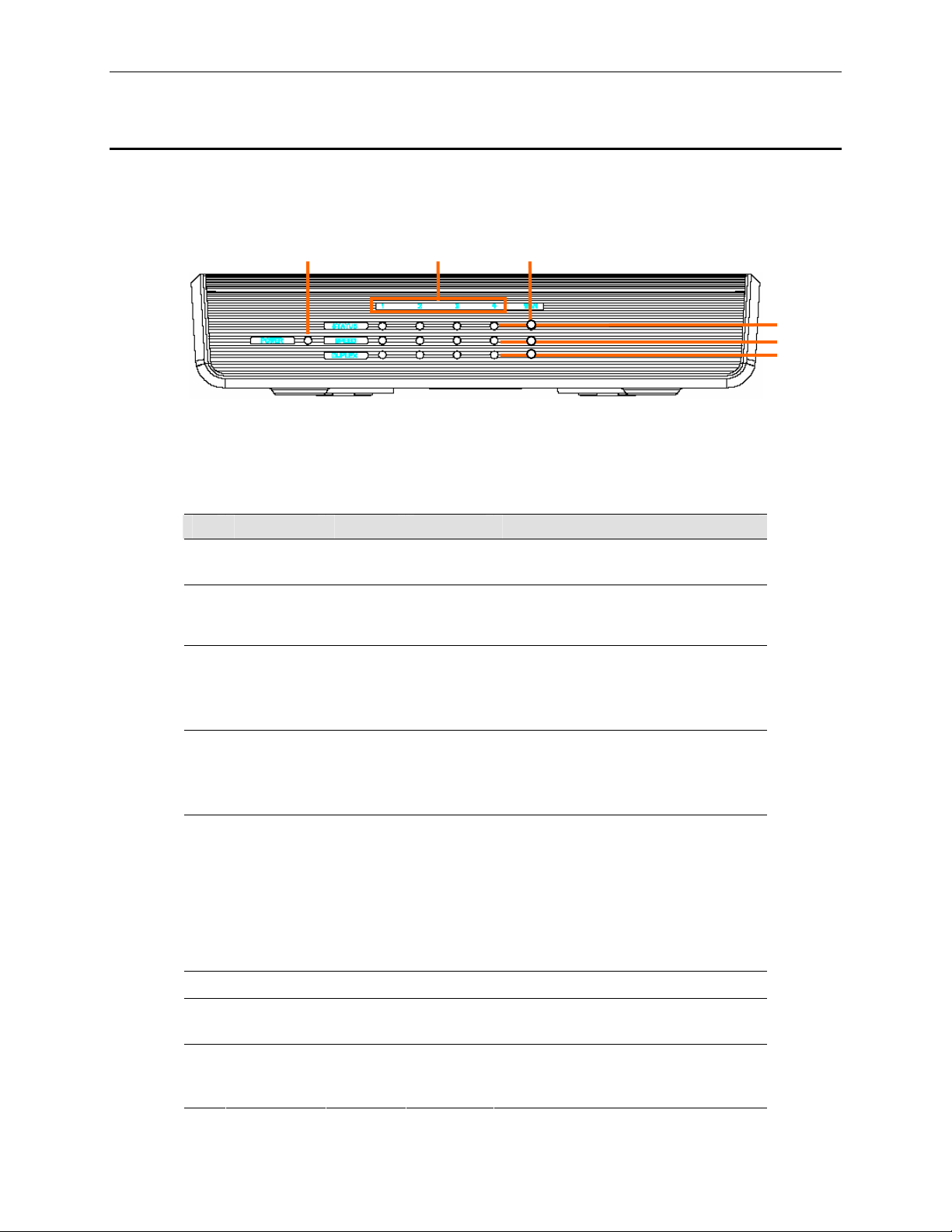
2.4.1 Front Panel
The front panel contains LED indicators th at show the status of the u nit.
1
○
○
Figure 2.1. Front Panel LEDs
Table 2.2. Front Panel Label an d LEDs
2
○
6
3
○
4
○
5
○
LED Label Color Status Indication
○
○
1
2
POWER
1 – 4
Green ON
OFF
RX3141 is powered on
RX3141 is powered off
Identifies the LAN port LEDs. Status of
each LAN port is indicated by 3 LEDs:
STATUS, SPEED and DUPLEX.
3
○
○
STATUS Green ON
4
SPEED Green
Amber
Blinking
OFF
ON
ON
OFF
Ethernet link is established and active
Data is transmitted or received via the
connection
No Ethernet link
Speed is 1000Mbps
Speed is 100Mbps
Speed is 10Mbps or no link is
established.
○
5
DUPLEX Amber
ON
Blinking
OFF
The LAN port is operating in full-duplex
mode.
The LAN port is operating in half-
duplex mode and collision is
occurring.
The LAN port is operating in half
duplex mode and no collision is
detected.
○
○
○
6
WAN
3
STATUS Green ON
4
SPEED Green ON
Identifies the WAN port LED
Ethernet link is established and active.
OFF
No Ethernet link is established.
Speed is 100Mbps
Blinking
Green: Data is transmitted or received
via the connection
6
Page 17

RX3141 User’s Manual Chapter 2 Getting to Know
LED Label Color Status Indication
Amber ON
Blinking
Speed is 10Mbps
Data is transmitted or received via the
connection
OFF No link is established.
○
5
DUPLEX Amber
ON
OFF
The LAN port is operating in full-duplex
mode.
The LAN port is operating in half
duplex mode and no collision is
detected.
2.4.2 Rear Panel
The rear panel contains the ports for the unit's data and power connections.
7
○
○
Figure 2.2. Rear Panel Connectors
Table 2.3. Rear Panel Labels and LEDs
8
10
○9○
Label Indication
○
7
1 – 4
LAN Ports: connects to your PC's Ethernet port, or
to the uplink port on your LAN's hub/switch, using
the Ethernet cable.
○
8
WAN
WAN Port: connects to your WAN device, such as
ADSL or cable modem.
9
RESET Reset Button
○
1. Reboots the device
2. Reset s the syst em config uration t o the f acto ry
defaults if pressed for more than 5 second s.
○
10
POWER
Power Input Jack: connects to the supplied AC
adapter
7
Page 18
Chapter 2. Getting to Know RX3141 User’s Manual
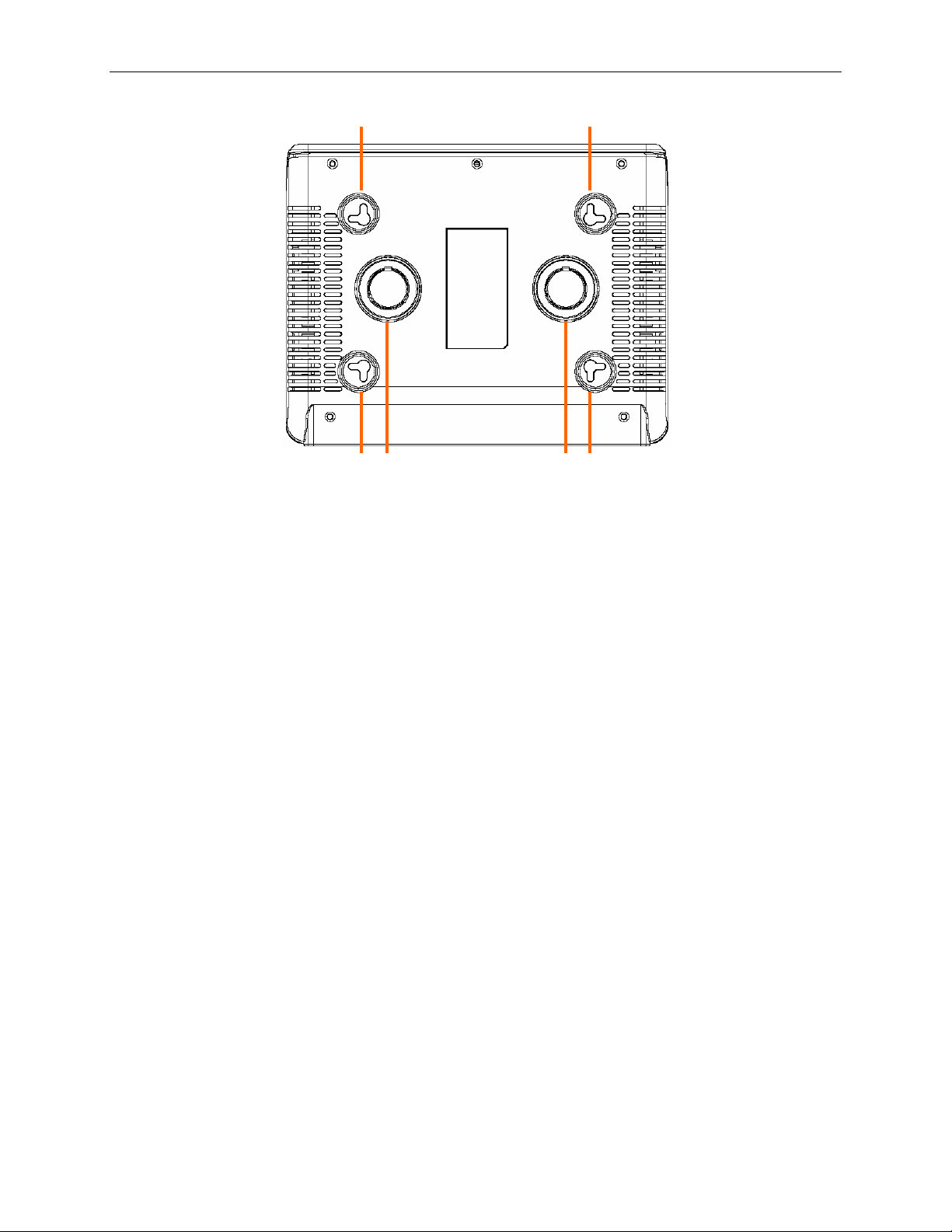
11
○
2.4.3 Bottom View
11
Wall Mount Slots: You may use these slots to hang RX3141 on the wall to save space. Depending on your
○
○
11
12
○
○
12
○
11
11
○
particular requirement by taking into account the location of the power outlet, power cord length, Ethernet
cable length and etc., you can hang RX3141 in 4 different orient ations: front pan el up, rear panel up, left
side up or right side up.
12
Magnets: The magnets allow you to place RX3141 on any metal surface to save space.
○
8
Page 19
RX3141 User’s Manual Chapter 2 Getting to Know
2.5 Placement Options
Depending on your environment, you may choose one of the three supported placement options for RX3141 –
desktop placement, magnet mount and wall mount.
2.5.1 Desktop Placement
You may place RX3141 on any flat surface. The space- saving design of RX31 41 occupies only a smal l area
on your desk.
2.5.2 Magnet Mount Instructions
Place RX3141 onto any metal surface that attracts magnet, such as most desktop computer housings,
cabinets and etc.
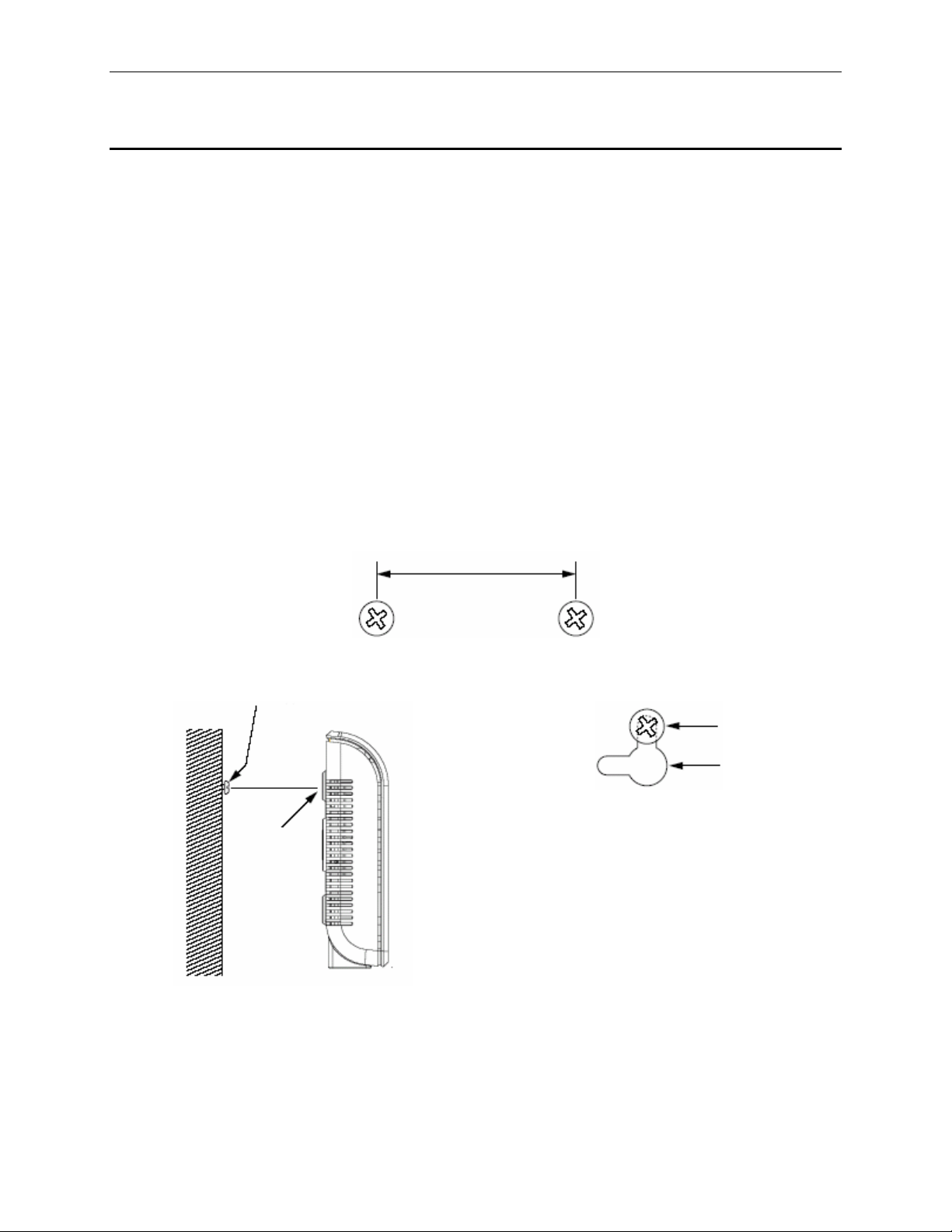
2.5.3 Wall Mount Instructions:
1. Attach two screws on the wall, separated by 115mm if you want the front or rear panel facing
upward, 76mm if you want left or right side facing upward. Make sure that the two screws are
leveled. Note that there are four wall mount slots and you may choose any adjacent slots for wall
mounting.
115mm or 76mm
2. Line up the wall mount slots with the screws and maneuver RX3141 so that both screws are
inserted into the wall mount slots as indicated in the following figures.
Screws
Screws
Wall
mount
Wall
mount
slots
Line up the wall mount slots w/ both screws.
Maneuver the switch so that both screws
are inserted into the wall mount slots.
slots
9
Page 20

Page 21
RX3141 User’s Manual Chapter 3. Quick Start Guide
3
This Quick Start Guide provides basic instructions for connecting the RX3141 to a computer or a network and
to the Internet.
f Part 1 provides instructions to set up the hardware.
f Part 2 describes how to configure Internet properties on your computer(s).
f Part 3 shows you how to configure basic settings on the RX3141 to get your LAN connected to the
After setting up and configuring th e devi ce, you can fo llow the instru ctions on p age 17 to v erify th at it is wo rking
properly.
This Quick Start Guide assumes that y ou have alrea dy establi shed ADS L or cabl e modem servic e with you r
Internet service provider (ISP). These instructions provide a basic configuration that should be compatible with
your home or small office network setup. Refer to the subsequent chapters for additional configuration
instructions.
Quick Start Guide
Internet.
3.1 Part 1 — Connecting the Hardware
In Part 1, you connect the device to an ADSL or a cable modem (which in turn is connected to a phone jack or
a cable outlet), the power outlet, and your comput er or networ k.
Before you begin, turn the power o ff for all d evices. These
include your computer(s), your LAN hub/swit ch (if appli cable),
WARNING
and the RX3141.
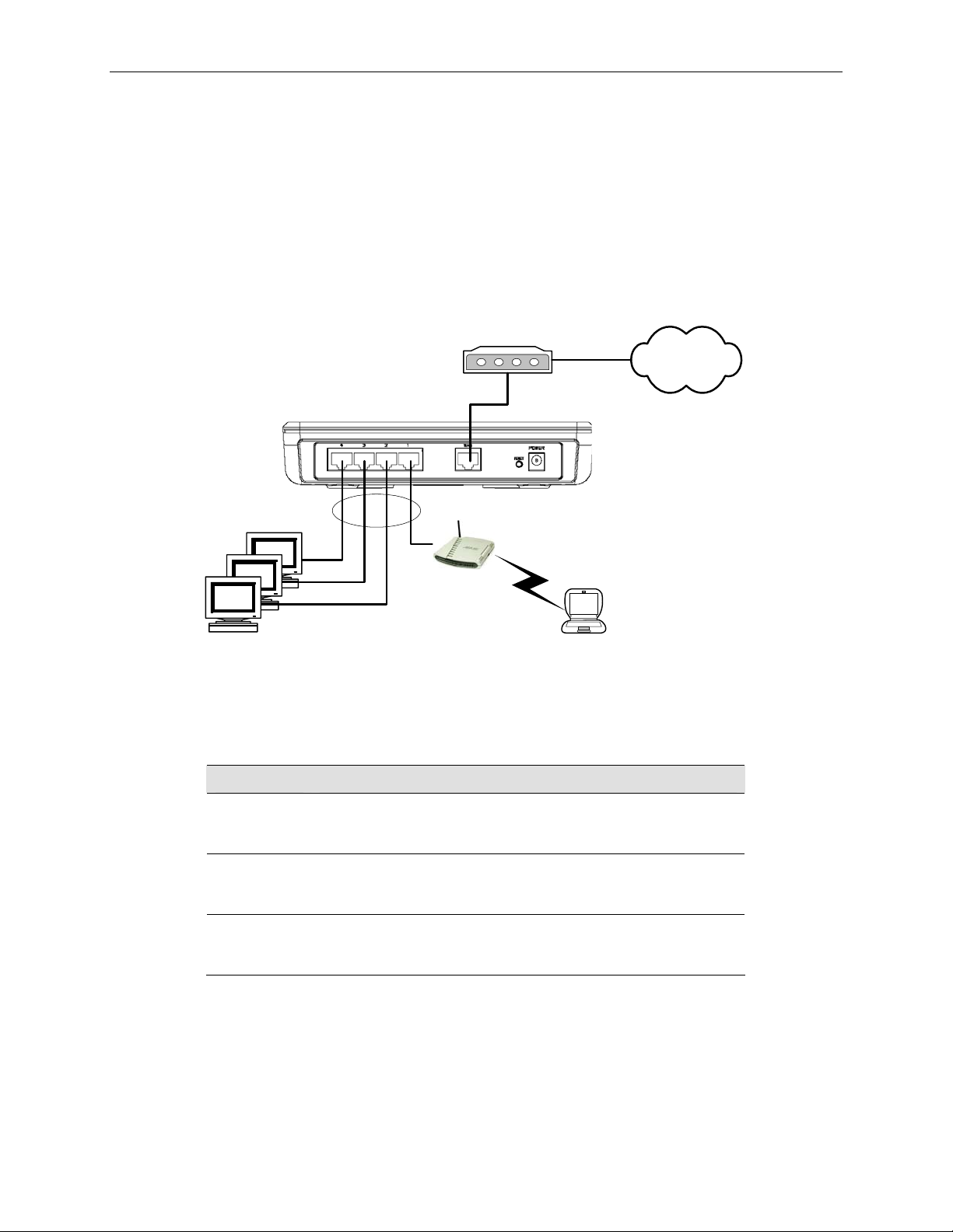
Figure 3.1 illustrates the hardware connections. Please follow the steps that follow for specific instructions.
3.1.1 Step 1. Connect an ADSL or a cable modem.
For the RX3141: Connect one end of the Ethernet cable to the po rt labeled WAN o n the rear panel of the
device. Connect the other en d to the Et hernet port on th e ADSL or cable mod em.
3.1.2 Step 2. Connect computers or a Network.
If your LAN has no more than 4 computers, you can use an Ethernet cable to connect computers directly to
the built-in switch on the device. Note that you should atta ch one end of the Ethernet cabl e to any of the port
labeled 1 – 4 on the rear pane l of the router a nd conne ct the other end to t he Ethe rnet port of a comput er.
If your LAN has more than 4 computers, you can attach one end of an Ethe rnet cable to a hub or a swit ch
(probably an uplink port; plea se refer to t he hub o r switch do cumentati ons for i nstru ctions) a nd the oth er to the
Ethernet switch port (labeled 1 – 4) on the RX3141.
Note that either the crossover or straight-through Ethernet cable can be used to connect the built-in switch and
computers, hubs or switches as the built-in switch is smart enough to make connections with either type of
cables.
11
Page 22
Chapter 3. Quick Start Guide RX3141 User’s Manual
3.1.3 Step 3. Attach the AC adapter.
Attach the AC adapter to the POWE R input j ack on the back of t he dev ice and pl ug in th e adapter to a wall
outlet or a power strip.
3.1.4 Step 4. Power on RX3141, the ADSL or cable modem and power up your
computers.
Plug the AC adapter to the powe r input ja ck of RX 3141. Turn o n your ADS L or cabl e mode m. Turn on an d
boot up your computer(s) and/or any LAN devices su ch as wireless A P, hubs or switches.
Internet
Cable or ADSL Modem
RX3141i
Ethernet
cable
Wireless AP
Figure 3.1. Overview of Hardware Connections
You should verify that the LEDs are illuminated as indica ted in Table 3.1.
Table 3.1. LED Indicators
This LED: ...should be:
POWER
1 – 4
STATUS
LED
WAN
If the LEDs illuminate as expected, the RX3141 is working properly.
Solid green to indicate that the device is turned on. If this light
is not on, check if the AC adapter is attached to the RX3141
and if it is plugged into a po wer sou rce.
Solid green to indicate that the device can communicate with
your LAN or flashing when the device is sending or receiving
data to/from your LAN com puter(s).
Solid green to indicate that the device has successfully
established a connection with your ISP or flashing when the
device is sending or receiving data to/from the Internet.
12
Page 23
RX3141 User’s Manual Chapter 3. Quick Start Guide
3.2 Part 2 — Configuring Your Computers
Part 2 of the Quick Start Guide provides instru ctions fo r configuring t he network se ttings on your comput ers to
work with the RX3141.
3.2.1 Before you begin
By default, the RX3141 automatically assigns all required network settings (e.g. IP address, DNS server IP
address, default gateway IP address) to your PCs. You need only to configure your PCs to accept the network
settings provided by the RX3141.
In some cases, you may want to configure network se ttings
manually to some or all of your computers rather than allow the
Note
f If you have connected your PC via Et hernet to t he RX 3141, foll ow the i nstructi ons that correspo nd to
the operating system installed on you r PC.
RX3141 to do so. See “Assigning static IP addresses to your PCs”
in page 15 for instructions.
3.2.2 Windows® XP PCs:
1. In the Windows task bar, click the
2. Double-click the Network Connections icon.
3. In the LAN or High-Speed Internet window, right-click on icon corresponding to your network
interface card (NIC) and select
The Local Area Connection dialog box displ ays with a list of current ly installed net work items.
4. Ensure that the check box to the left of the item labeled Internet Protocol TCP/IP is checked, and
click
<Properties>
5. In the Internet Protocol (TCP/IP) Properties dialog box, click the radio button labeled
IP address automatically
automatically
<OK>
6. Click
button twice to confirm your changes, and close the Control Panel.
button.
. Also click the radio button labeled
.
<Start>
Properties
button, and then click
. (Often this icon is labeled Local Area Connection).
Control Panel
Obtain DNS server address
.
Obtain an
3.2.3 Windows® 2000 PCs:
First, check for the IP protocol and, if ne cessary, instal l it:
1. In the Windows task bar, click the
Panel
.
2. Double-click the
3. In the Network and Dial-up Connections window, right-click the
and then select
Network and Dial-up Connections
Properties
.
<Start>
button, point to
icon.
Settings
, and then click
Local Area Connection
Control
icon,
The Local Area Connection Properties dialog box displays a list of currently installed network
components. If the list includes Internet Protocol (TCP/IP), then the protocol has already been
enabled. Skip to step 10.
4. If Internet Protocol (TCP/IP) does not display as an installed component, click
13
<Install>
button.
Page 24

Chapter 3. Quick Start Guide RX3141 User’s Manual
5. In the Select Network Component Type dialog box, select
6. Select
Internet Protocol (TCP/IP)
in the Network Protocols list, and then click
Protocol
, and then click
You may be prompted to install files from your Windows 2000 installation CD or other media. Follow
the instructions to install t he files.
7. If prompted, click
<OK>
button to restart your computer with the new settings.
Next, configure the PCs to accept IP a ddresses a ssigned by t he RX3 141:
8. In the Control Panel, double-click the
9. In Network and Dial-up Connections window, right-click the
then select
Properties
.
10. In the Local Area Connection Properties dialog box, select
click
<Properties>
button.
Network and Dial-up Connections
Local Area Connection
Internet Protocol (TCP/IP)
icon.
11. In the Internet Protocol (TCP/IP) Properties dialog box, click the radio button labeled
IP address automatically
automatically
12. Click
<OK>
.
button twice to confirm and save your changes, and then close the Control Panel.
. Also click the radio button labeled
Obtain DNS server address
3.2.4 Windows® 95, 98, and Me PCs
1. In the Windows task bar, click the
Panel
.
<Start>
button, point to
Settings
, and then click
<OK>
Control
<Add>
button.
button.
icon, and
, and then
Obtain an
2. Double-click the
In the Network dialog box, look for an entry start ed w/ “
adapter, and then click
Network
icon.
<Properties>
TCP/IP ->
” and the name of your network
button. You may have to scroll down the list to find this entry.
If the list includes such an entry, then the TCP/IP protocol has already been enabled. Skip to step 8.
3. If Internet Protocol (TCP/IP) does not display as an installed component, click
4. In the Select Network Component Type dialog box, select
5. Select
list, box and then click
Microsoft
in the Manufacturers list box, and then click
<OK>
button.
Protocol
TCP/IP
, and then click
in the Network Protocols
<Add>
<Add>
You may be prompted to install files from your Windows 95, 98 or Me installation CD or other
media. Follow the instruction s to instal l the file s.
6. If prompted, click
<OK>
button to restart your computer with the new settings.
Next, configure the PCs to accept IP i nformation a ssigned by t he RX3 141:
7. In the Control Panel, double-click the Network icon.
8. In the Network dialog box, select an entry started with “
adapter, and then click
<Properties>
button.
9. In the TCP/IP Properties dialog box, click the radio button labeled
automatically
10. In the TCP/IP Properties dialog box, click the “
.
Default Gateway
default LAN port IP address of the RX3141) in the “
TCP/IP ->”
New gatewa y
and the name of your network
Obtain an IP address
” tab. Enter 192.168.1.1 (the
” address field and click
button to add the default gateway entry.
button.
button.
<Add>
11. Click
<OK>
button twice to confirm and save your changes, and then close the Control Panel.
12. If prompted to restart your computer, click
14
<OK>
button to do so with the new settings.
Page 25

RX3141 User’s Manual Chapter 3. Quick Start Guide
3.2.5 Windows® NT 4.0 workstations:
First, check for the IP protocol and, if ne cessary, instal l it:
1. In the Windows NT task bar, click the
Panel
.
2. In the Control Panel window, double click the
3. In the Network dialog box, click the
The Protocols tab displays a li st of currently in stalle d network protocol s. If the li st include s TCP/IP
Protocol, then the protocol has already been enabled. Skip to step 9.
4. If TCP/IP does not display as an installed component, click
5. In the Select Network Protocol dialog box, select
You may be prompted to install files from your Windows NT installation CD or other media. Follow
the instructions to install t he files.
After all files are installed, a window di splays t o inform y ou that a TCP/IP servi ce call ed DHCP can
be set up to dynamically assign IP information.
6. Click
7. Open the Control Panel window, and then double-click the
8. In the Network dialog box, click the
9. In the Protocols tab, select
10. In the Microsoft TCP/IP Properties dialog box, click the radio button labeled
<Yes>
button to continue, and then click
Next, configure the PCs to accept IP a ddresses a ssigned by t he RX3 141:
TCP/IP
address from a DHCP server
.
<Start>
Protocols
Protocols
, and then click
button, point to
Network
tab.
<OK>
tab.
icon.
TCP/IP
, and then click
button if prompted to restart your computer.
<Properties>
Settings
<Add>
Network
button.
button.
, and then click
<OK>
button.
icon.
Obtain an IP
Control
11. Click
<OK>
button twice to confirm and save your changes, and then close the Control Panel.
3.2.6 Assigning static IP addresses to your PCs
In some cases, you may want to assign IP addresses to some or all of your PCs di rectly (often called
“statically”), rather than allowing the RX3141 to assign them. This option may be desirable (but not required) if:
f You have obtained one or mo re public IP addresse s that yo u want to always asso ciate wit h spe cific
computers (for example, if you are using a computer as a public web server).
f You maintain different subnets on your LAN.
However, during the first time configurati on of yo ur RX3141, y ou must assi gn an IP ad dress in the 192.16 8.1.0
network for your PC, say 192.168.1.2, in order to establish connection between the RX3141 and your PC as
the default LAN IP on RX3141 is pre-configured a s 192.168. 1.1. Ente r 255.25 5.255. 0 for t he subn et mask an d
192.168.1.1 for the default gateway. These sett ings may be changed lat er to reflect your true net work
environment.
On each PC to which you want to assign static information, follow the instructions on pages 13 through 15
relating only to checking fo r and/or instal ling th e IP protoco l. Once it is i nstall ed, conti nue to foll ow the
instructions for displaying each of the Internet Protocol (TCP/IP) properties. Instead of enabling dynamic
assignment of the IP addresse s for the computer, DNS serv er, and default gat eway, click th e radio button s that
enable you to enter the informatio n manually.
Your PCs must have IP addresses that place them in the same subnet as the RX3141’s
LAN port. If you manually assi gn IP inform ation t o all you r LAN P Cs, you can foll ow the
Note
instructions in the section 5.1.1 to chan ge the LAN port IP add ress accordin gly.
15
Page 26
Chapter 3. Quick Start Guide RX3141 User’s Manual
3.3 Part 3 — Quick Configuration of the RX3141
In Part 3, you log into the Configuration Manager o n the RX3141 and conf igure basic setting s for your route r.
Your ISP should provide you wit h the necessa ry inform ation to complete thi s step. Note the i ntent here i s to
quickly get the RX3141 up and running, instructions are concise. You may refer to corresponding chapters for
more details.
3.3.1 Setting Up the RX3141
Follow these instructions to setup the RX3141:
1. Before accessing the Configuration Manager in RX3141, make sure that the HTTP proxy setting
is disabled in your browser. In IE, click “
“
LAN settings…
2. On any PC connected to one of the four LAN ports on the RX3141, open your Web browser, and
type the following URL in the address/location box, and press
This is the predefined IP address for the LAN port on the RX3141.
A login screen displays, as shown in Figure 3.2.
” and then uncheck “
Tools
” Î “
Internet Options…
Use proxy server for your LAN …
<Enter>
http://192.168.1.1
” Î “
”
:
Connections
” tab Î
Figure 3.2. Login Screen
If you have problem connecting to the RX3141, you may want to check if your PC is configured to
accept IP address assignment from the RX3141. Another method is to set the IP address of your PC
to any IP address in the 192.168.1.0 network, such as 192.1 68.1.2.
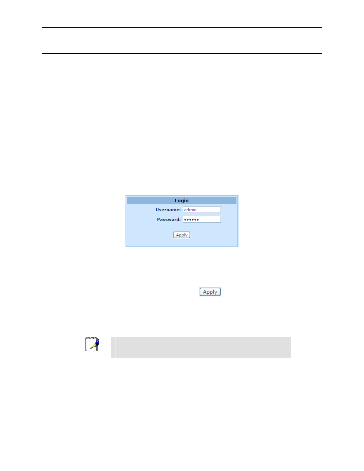
3. Enter your username and password, and then click
The first time you log into this program, use these defaults:
Default Username:
Default Password:
You can change the password at any time (see section 11.1 Lo gin
Note
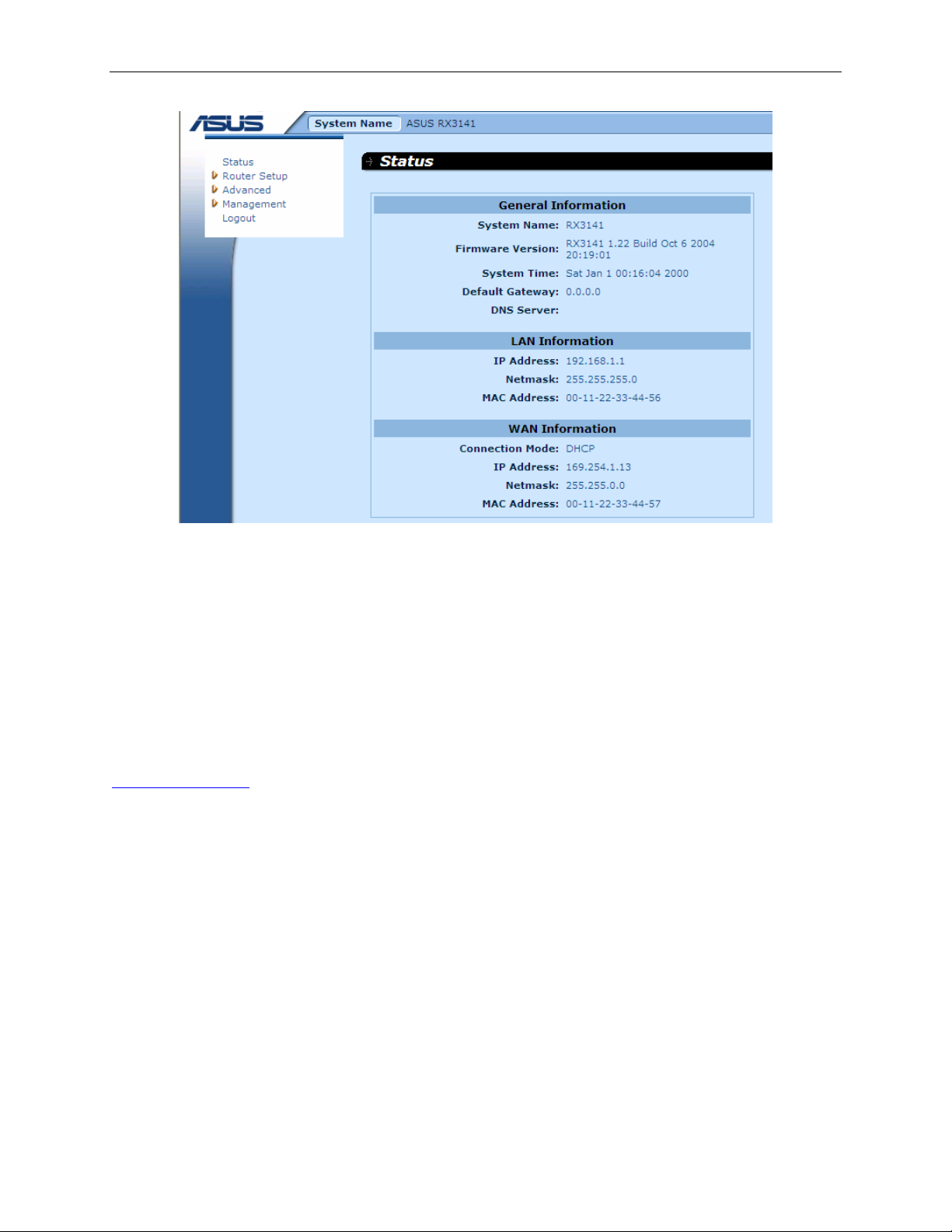
The System Information page di splays each time y ou log into t he Co nfiguratio n Manag er (sho wn in
Figure 3.3).
Password and System-Wide Settings ).
admin
admin
to enter the Configuration Manager.
16
Page 27
RX3141 User’s Manual Chapter 3. Quick Start Guide
Figure 3.3. System Status Page
4. Follow the instructions described in Chapter 5 "Router Connection Setup” to set up the LAN and
WAN settings for RX3141.
After completing the basic conf iguratio n for RX3141, re ad the foll owing section t o determi ne if you can access
the Internet.
3.3.2 Testing Your Setup
At this point, the RX3141 should enable any comput ers on your LA N to use the RX314 1’s ADSL or cable
modem connection to access the Internet.
To test the Internet connection, open you r web brow ser, and ty pe the URL of any exte rnal webs ite (such as
http://www.asus.com
connects to the site. You should also be able to browse the web site through your web browser.
If the LEDs do not illuminate as expected or the web page does not display, see Appendix 13 for
troubleshooting suggestions.
). The LED labeled WAN should be blinkin g rapidly and may appear solid as the
device
17
Page 28

Chapter 3. Quick Start Guide RX3141 User’s Manual
3.3.3 Default Router Settings
In addition to handling the DSL connection to your ISP, the RX314 1 can provide a variety of service s to your
network. The device is pre-configured wit h default setti ngs for use with a typical ho me or small office net work.
Table 3.2 lists some of the most important default setting s; these and othe r features are describ ed fully in the
subsequent chapters. If you are familiar with network configuration settings, review the settings in Table 3.2 to
verify that they meet the needs of your network. F ollow the instructions to change them if necessary. If you are
unfamiliar with these settings, t ry using t he devi ce without modification, or contact your ISP for assistance.
Before you modifying any settings, review Chapter 4 for ge neral informati on about accessi ng and using the
Configuration Manager program. We strongly recommend that you contact your ISP prior to changing the
default configuration.
Table 3.2. Default Settings Summ ary
Option Default Setting Explanation/Instructions
DHCP (Dynamic
Host
Configuration
Protocol)
DHCP server enabled with the
following pool of addresses:
192.168.1.100 through
192.168.1.149
The RX3141 maintains a pool of priv ate IP
addresses for dynamic assignment to your
LAN computers. To use thi s service, you
must have set up your computers to
accept IP information dynamically, a s
described in Part 2 of the Quick Start
Guide. See section 6.1 for a n expla nation
of the DHCP service.
LAN Port IP
Address
Static IP address: 192.168.1.1
subnet mask: 255.255.255. 0
This is the IP address of the LA N port on
the RX3141. The LAN port connects the
device to your Ethernet network. Typi cally,
you will not need to change this address.
See section 5.1.1 LAN IP Address for
instructions.
18
Page 29
RX3141 User’s Manual Chapter 4. Using the Configuration Manager
4
The RX3141 includes a preinstalled program called the Configuration Manager, which provides an interface to
the software installed on the device. It enables y ou to conf igure th e device sett ings to m eet the ne eds of y our
network. You access it through your web browser fro m any PC co nnected t o the RX 3141 via
WAN ports.
This chapter describes the general guides for using the Configuration Manager.
Using the Configuration Manager
the LAN or the
4.1 Log into the Configuration Manager
The Configuration Manager program is preinstalled on the RX3141. To access the program, you need the
following:
f A computer connected to the LAN or WAN port on the RX3141 as described in the Quick Start Guide
chapter.
f A web browser installed on the computer. The program is designed to work best with Microsoft
Internet Explorer® 6.0 or later.
You may access the program from any computer connected to the RX3141 via the L AN or WAN ports.
However, the instructions p rovided here are fo r compute rs conne cted via t he LA N ports.
1. From a LAN computer, open your web browser, type the following in the web address (or
location) box, and press
<Enter>
:
http://192.168.1.1
This is the predefined IP address for the LAN port on the RX3141. A login screen displays, as shown
in Figure 4.1.
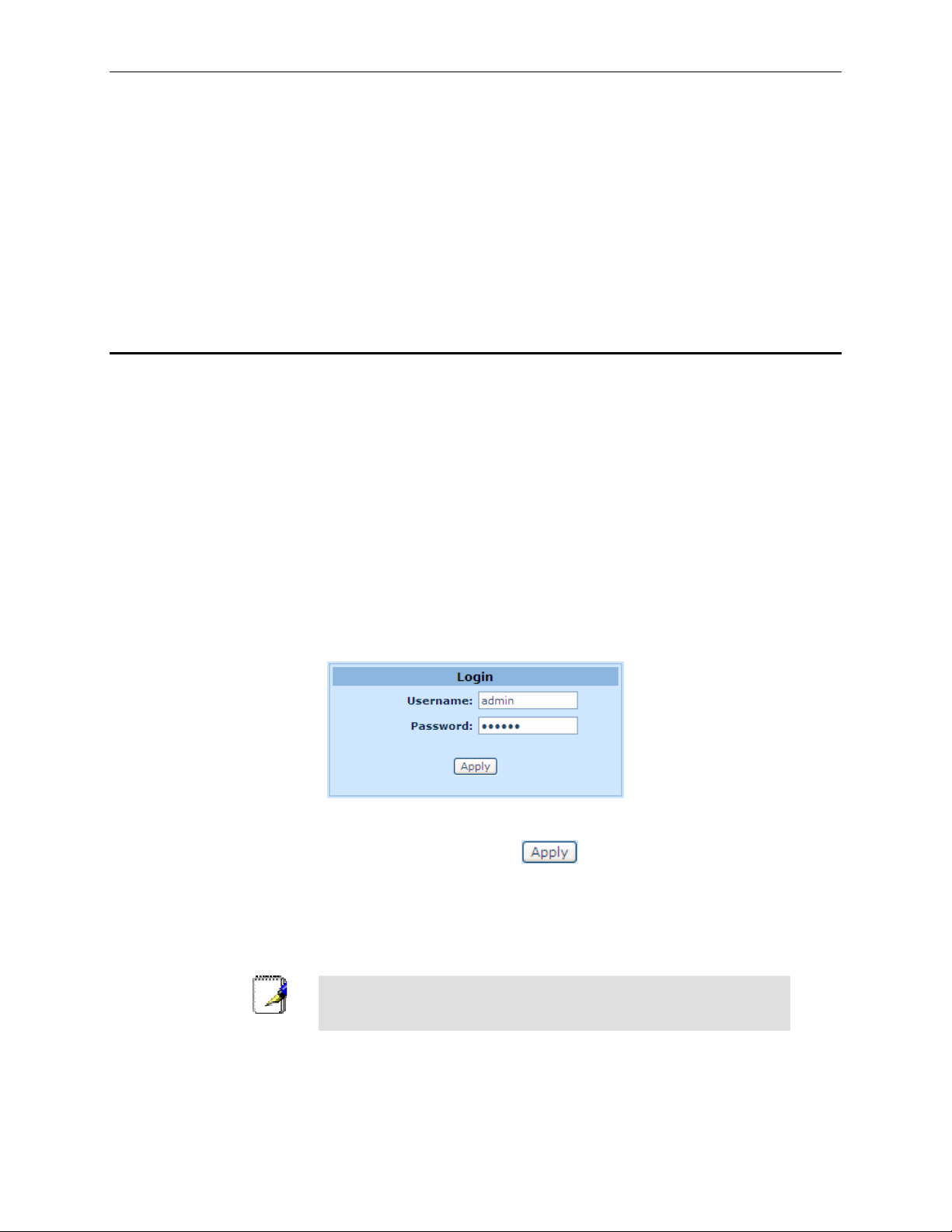
Figure 4.1. Configuration Manager Login Screen
2. Enter your username and password, and then click
The first time you log into the program, use thes e defaults:
Default Username:
Default Password:
You can change the password at any time (see section 11.1 Lo gin
Note
The System Information page displays ev ery time you log int o the Configurati on Manag er (shown in
Figure 4.3 on page 22).
Password and System-Wide Settings ).
admin
admin
.
19
Page 30
Chapter 4. Using the Configuration Manager RX3141 User’s Manual
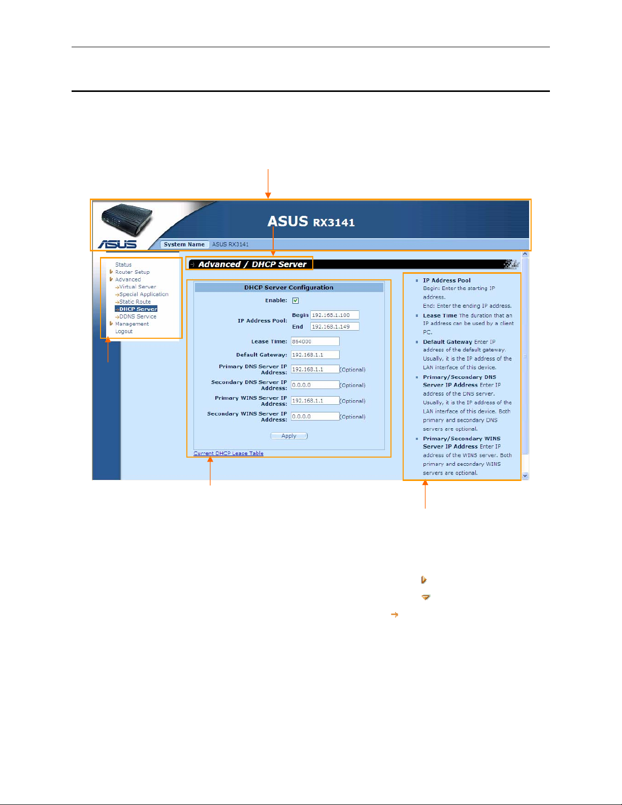
4.2 Functional Layout
Typical Typical Configuration page consis ts of several elem ents – banner, men u, menu navigatio n tips,
configuration, and on-line help. You can click on any menu item to expand/contract any menu groups or to
access a specific configuration page. The conf iguratio n pane is where you int eract wit h the Configur ation
Manager to configure the settings for RX3141. Menu navigation tips show how the current configuration can
be accessed via the menus.
Banner
Menu navigation tips
Menu
Configuration
Figure 4.2. Typical Configur ation Man ager Page
4.2.1 Menu Navigation
f To expand a group of related menus: double cli ck the menu or th e icon, .
f To contract a group of related menus: double click the menu or the icon,
f To open a specific configuration page, click the menu or the ico n,
Online Help
.
.
20
Page 31

RX3141 User’s Manual Chapter 4. Using the Configuration Manager
4.2.2 Commonly Used Buttons and Icons
The following buttons or icon s are used th roughout th e appli cation. T he follo wing ta ble descri bes the fu nction
for each button or icon.
Table 4.1. Description of Commonly Used Button s and Icons
Button/Icon Function
Stores any changes you have made on the current page.
Adds a new configuration to the syste m, e.g. a static route or a fire wall ACL rule and et c.
Modifies existing configuration in the sy stem, e.g. a stat ic route or a fire wall ACL rule an d etc.
Redisplays the current page with updated statistics or settings.
Selects the item for editi ng.
Trash -
Browse
Undo
Cancel
OK
Open
Save
Folder Off
Folder On
Item
Deletes the selecte d item.
21
Page 32

Chapter 4. Using the Configuration Manager RX3141 User’s Manual
4.3 Overview of System Configuration
To view the overall system configuratio n, log into the Config uration Man ager, and then cl ick
Figure 4.3 shows sample inform ation av ailable in the Sy stem I nformati on page.
Status
menu.
Figure 4.3. System Information Page
22
Page 33

RX3141 User’s Manual Chapter 5 Router Connection Setup
5
This chapter describes how to configure the basic settings for your router so that the computers on your LAN
can communicate with each other and have access to the Internet. Network setup consists of LAN and WAN
configurations.
Router Connection Setup
5.1 LAN Configuration
5.1.1 LAN IP Address
If you are using RX3141 with multipl e PCs on y our LAN, you must co nnect you r LAN t o the Ethernet ports on
the built-in Ethernet switch. You must assign a uniq ue IP address to each dev ice residi ng on your LAN. The
LAN IP address that identifies the RX3141 as a node on your network must be in the same subnet as the PCs
on your LAN. The default LAN IP address for the RX3141 is 192.168.1.1.
A network node can be thought of as any interface where a
device connects to the network, such as the RX3141’ s LAN port
Definition
You can change the default IP address to reflect the true IP address that you want to use with your netwo rk.
and the network interface cards on your PCs. See Appendix 12 for
an explanation of subnets.
5.1.2 LAN Configuration Parameters
Table 5.1 describes the config uration pa ramet ers av ailabl e for LA N IP conf igurat ion.
Table 5.1. LAN Configuration Paramete rs
Setting
Host Name
IP Address
Subnet Mask
Description
For identification only.
The LAN IP address of the RX3141. This IP address is used by your
computers to identify the RX3141’s LAN port. Note that the public IP address
assigned to you by your ISP
address identifies the WAN port on the RX3141 to the Internet.
The LAN subnet mask identifies which parts of the LAN IP Address refer to
your network as a whole and which parts refer specifically to nodes on the
network. Your device is preconf igured wit h a def ault sub net mask of
255.255.255.0.
is not
your LAN IP address. The public IP
23
Page 34

Chapter 5 Router Connection Setup RX3141 User’s Manual
5.1.3 Configuring the LAN IP Address
Follow these steps to change the default LAN IP address.
1. Log into Configuration Manager, and then double click
Router Setup
Î
Connection
menu. The
Router Connection Setup configuration page is then displayed as shown in Figure 5.1.
Figure 5.1. Router Connection Setup Configuration – LAN Configuration
2. (Optional) Enter the host name for RX3141. Note that the host name is used for identification only
and is not used for any other purpose.
3. Enter the LAN IP address and subnet mask for the RX3141 in the spaces provided.
4. Proceed to the WAN Configuration section for instructions on setting up the WAN port if you have
not yet done so.
5. Click
to save the settings. If you are using an Ethernet connection for the current
session, and change the IP address, the connection will be terminated.
6. You will see the following message displayed as shown below.
7. You will then be prompted to log back into the Configuration Manager once the timer elapses.
24
Page 35

RX3141 User’s Manual Chapter 5 Router Connection Setup
5.2 WAN Configuration
This section describes how to config ure WAN settings fo r the WA N int erface on t he RX31 41 that
communicates with your ISP. You’l l learn to config ure IP add ress, DHCP and DNS serve r for y our WAN in this
section.
5.2.1 WAN Connection Mode
Four modes of WAN connection are supported by the RX3141 – PPPoE (multi-session), PPPoE unnumbered,
dynamic IP and static IP. You may select one of the WAN connection modes required by your ISP from the
Connection Mode drop-down list in Network Setup Configuration page as shown in Figure 5.2.
Connection
Mode dropdown list
Figure 5.2. Network Setup Configuration Pa ge – WAN Con figuration
25
Page 36

Chapter 5 Router Connection Setup RX3141 User’s Manual
5.2.2 PPPoE
PPPoE connection is most often used by ADSL service providers.
Connection
Mode dropdown list
Figure 5.3. WAN – PPPoE Configuration
26
Page 37

RX3141 User’s Manual Chapter 5 Router Connection Setup
5.2.2.1 WAN PPPoE Configuration Parameters
Table 5.2 describes the configuration parameters available for PPPoE connection mode.
Table 5.2. WAN PPPoE Configuration Parameters
Setting Description
Connection Mode
Select
PPPoE
from the connection mode drop-down list.
PPPoE Session
Enable
Connection on Demand
Disconnect after Idle (min)
User Name and Password
Service Name
IP Address
Primary/Secondary DNS
Server
Status
Manual
Disconnect/Connect
Select the PPPoE session ID for th is PPPoE sessio n. Note th at only two
simultaneous PPPoE sessions are supported.
Check or uncheck this box to activate this PPPoE session.
Check “
Enable
” or “
Disable
” radio button to enable/ disabl e this opti on.
Enter the inactivity timeout period at which you want to disconnect the Internet
connection when there is no traffic. A value of 0 means no activity time out.
Note that SNTP service may interfere wit h this function if there are activities
from the service.
Enter the username and password y ou use to log into y our ISP. (Not e: this is
different from the information you used t o log into Configurati on Manager.)
Enter the service name provided by your ISP. Servic e name is option al but
may be required by some ISP.
Enter a static IP address here only when your service provider requires a
static IP for PPPoE connection. This IP address must be provided by your
service provider. Most service providers do not require user to use a static IP
for PPPoE connection.
IP address of the primary and/or secondary DNS are optional as PPPoE will
automatically detect the DNS IP addr esses conf igured at your ISP. However,
if there are other DNS servers y ou woul d rather use, enter the IP addre sses
in the spaces provided.
On: PPPoE connection is active.
Off: PPPoE connection is inactive.
Connecting: RX3141 is trying to connect to your ISP using PPPoE connection
mode.
Click the
Disconnect
or
Connect
button to disconnect or connect to your
service provider using the PPPoE connection mode.
27
Page 38

Chapter 5 Router Connection Setup RX3141 User’s Manual
5.2.2.2 Configuring PPPoE for WAN
Follow the instructions below to configure PPPoE settings:
1. Open the Router Connection configuration page by double clicking the
Connection
2. Select
menu.
PPPoE
from the WAN Connection Mode drop-down list as shown in Figure 5.3.
Router Setup
Î
3. Select PPPoE session ID from the PPPoE session ID drop-down list. Currently, two sessions are
supported.
4. Enter the user name and password provided by your ISP.
5. (Optional) Enter the service name if required by your ISP.
6. Enter appropriate connection settings for “
Demand
7. Click
”.
to save the settings.
Disconnect after Idle (min)
” and “
Connect on
5.2.2.3 Configuring PPPoE Multi-session for WAN
Follow the instructions below to configure PPPoE multi-session settings for the PPPoE mult i-session ex ample
as shown in Figure 5.4.
myService
Internet
ISP
211.0.0.0/8
*.myserv.net
PPPoE0
PPPoE1
RX3141
Figure 5.4. WAN – PPPoE Multi-session Example
1. Open the Router Connection configuration page by double clicking the
Connection
menu.
Router Setup
2. Configure PPPoE settings as you normally would for each PPPoE session as described in
section 5.2.2.2 “Configuring PPPoE for WAN”. Note that maximum of two PPPoE sessions are
supported. The following figures show the settings for the two PPPoE sessions.
28
Î
Page 39

RX3141 User’s Manual Chapter 5 Router Connection Setup
Figure 5.5. WAN – PPPoE0 Settings Figure 5.6. WAN – PPPoE1 Settings
3. Configure firewall outbound ACL rules to forward the designated traffic to each intended PPPoE
session. Please refer to section 9.5 “Configuring Outbound ACL Rules” for instructions on setting
up ACL rules. Figure 5.7 and Figure 5.8 show the settings for the two outbound ACL rules – one
specify the destination network using the network address and subnet mask and the other using
the domain name. Only one of the two ACL rules is needed. However, if you intend to use IP
address and the domain name to access the myService network, you’ll need to configure both
rules.
Figure 5.7. WAN – First ACL Rule Settings (using
network address/subnet mask) for Forwarding
Packets to PPPOE1 Session
Figure 5.8. WAN – Second ACL Rule Se ttings
(using domain name) for Forwarding Pa ckets to
PPPOE1 Session
4. Verify that you have all the rules properly configured as indicated in the “Existing Outbound ACL”
table as shown in Figure 5.9. Note that the third rule is the default outbound ACL rule that allows
all the outbound traffic to go through the firewall. You’ll have to configure this rule (see the default
outbound ACL settings in Figure 5.10) if you had deleted. The third rule is used to forward all the
outbound traffic to PPPoE0 session except those intended for PPPoE1 session.
29
Page 40

Chapter 5 Router Connection Setup RX3141 User’s Manual
Figure 5.9. WAN – Outbound ACL Rule Settings for PPPoE Multi-session Example
Figure 5.10. WAN – Default Outbound ACL Rule for PPPoE Multi-session Example
30
Page 41

RX3141 User’s Manual Chapter 5 Router Connection Setup
5.2.3 PPPoE Unnumbered
Some of the ADSL service providers may offer PPPoE unnumbered service. Choose this connection mode if
your ISP provides such service.
Connection
Mode dropdown list
Figure 5.11. WAN – PPPoE Unnumbered Configuration
31
Page 42

Chapter 5 Router Connection Setup RX3141 User’s Manual
5.2.3.1 WAN PPPoE Unnumbered Configuration Parameters
Table 5.3 describes the configuration parameters available for PPPoE unnumbered connection mode.
Table 5.3. WAN PPPoE Unnumbered Configuration Parameters
Setting Description
Connection Mode
Enable NAPT
Select
PPPoE Unnumbered
from the connection mode drop-down list.
Traditionally, each network interface must have a unique IP add ress.
However, an unnumbered interface does not have to have a unique IP
address. This means that when this optio n is selected, the WAN and the LA N
use the same IP address. Network resources are therefore conserved
because fewer network IP addresses a re used and ro uting table i s smaller.
Check or uncheck this box to enable NAPT for this connection.
Connect on Demand
Disconnect after Idle
(min)
IP Address
Unnumbered network
address
Unnumbered netmask
User Name and
Password
Service Name
Status
Manual
Disconnect/Connect
Check “
Enable
” or “
Disable
” radio button to enable/ disabl e this opti on.
Enter the inactivity timeout period at which you want to disconnect the Internet
connection when there is no traffic. A value of 0 means no activity time out.
Note that SNTP service may interfere wit h this function if there are activities
from the service.
Enter a static IP address here for the PPPoE unnumbered connection. This
IP address must be provided by your service provider.
Enter the network address provi ded by y our ISP.
Enter the subnet mask provided by your ISP.
Enter the username and password y ou use to log int o your ISP. (Not e: this is
different from the information you used t o log into Configurati on Manager.)
Enter the service name provided by your ISP. Servic e name is option al but
may be required by some ISPs.
On: PPPoE unnumbered connection is active.
Off: No PPPoE unnumbered connection is inactive.
Connecting: RX3141 is trying to connect to your ISP using PPPoE
unnumbered connection mode.
Click the
Disconnect
or
Connect
button to disconnect or connect to your
service provider using the PPPoE unnumbered connection mode.
32
Page 43

RX3141 User’s Manual Chapter 5 Router Connection Setup
5.2.3.2 Configuring PPPoE Unnumbered for WAN
Follow the instructions below to configure PPPoE unnumbered settings:
1. Open the Router Connection configuration page by double clicking the
Connection
2. Select
5.11.
3. Enter user name and password provided by your ISP..
4. (Optional) Enter the service name if required by your ISP.
5. Enter appropriate connection settings for “
Demand
6. Click
menu.
PPPoE Unnumbered
”.
to save the settings.
from the WAN Connection Mode drop-down list as shown in Figure
Disconnect after Idle (min)
5.2.4 Dynamic IP
Dynamic IP is most often used by the cable mod em service provi ders.
Figure 5.12. WAN – Dynamic IP (DHCP client) Configuration
Router Setup
” and “
Connect on
Connection
Mode dropdown list
Î
5.2.4.1 Configuring Dynamic IP for WAN
Follow the instructions belo w to confi gure dyna mic IP sett ings:
1. Open the Router Connection configuration page by double clicking the
2. Select Dynamic from the Connection Mode drop-down list as shown in Figure 5.12. Note that the
IP addresses for the primary and/or the secondary DNS servers are automatically assigned by
the DHCP server of your ISP.
3. Click
33
to save the settings.
Router Setup
Î menu.
Page 44

Chapter 5 Router Connection Setup RX3141 User’s Manual
5.2.5 Static IP
Connection
Mode dropdown list
Figure 5.13. WAN – Static IP Configuration
5.2.5.1 WAN Static IP Configuration Parameters
Table 5.4 describes the configuration parameters available for static IP connection mode.
Table 5.4. WAN Static IP Configuration Parameters
Setting Description
Connection Mode
IP Address
Subnet Mask
Gateway Address
Primary/Secondary
DNS Server
Select
Static
from the connection mode drop-down list.
WAN IP address provided by your ISP.
WAN subnet mask provided by your ISP. Typically, it is set as 255.255.255.0.
Gateway IP address provided by your ISP. It must be in the same subnet as
the WAN on the RX3141.
You must at least enter the IP address of the primary DNS server. Secondary
DNS server is optional
5.2.5.2 Configuring Static IP for WAN
Follow the instructions below to configure static IP settin gs:
1. Open the Router Connection configuration page by double clicking the
Connection
2. Select Static from the Connection Mode drop-down list as shown in Figure 5.13.
3. Enter WAN IP address in the IP Address field. This information should be provided by your ISP.
4. Enter Subnet Mask for the WAN. This information should be provided by your ISP. Typically, it is
255.255.255.0.
menu.
Router Setup
Î
5. Enter gateway address provided by your ISP in the space provided.
6. Enter the IP address of the primary DNS server. This information should be provided by your ISP.
Secondary DNS server is optional.
7. Click
.
34
to save the settings
Page 45

RX3141 User’s Manual Chapter Error! Reference source not found.. Error! Reference source not found.
6
DHCP Server Configuration
6.1 DHCP (Dynamic Host Control Protocol)
6.1.1 What is DHCP?
DHCP is a protocol that enables network administ rators to centrally man age the assignm ent and distri bution of
IP information to computers on a network.
When you enable DHCP on a network, you allow a device — such as the RX3141 — to assign temporary IP
addresses to your computers whenever they connect to your network. The assigning device is called a DHCP
server, and the receiving device is a DHCP client.
If you followed the Quick Sta rt Guide i nstru ction s, you eit her
configured each LAN PC with an IP address, or you specified that
Note
The DHCP server draws from a defined pool of IP addresses and “leases” them for a specified amount of time
to your computers when they request an Internet session. It monitors, collects, and redistributes the addresses
as needed.
it will receive IP information dynamically (automatically). I f you
chose to have the informati on assig ned dy namicall y, the n you
configured your PCs as DHCP clients that will accept IP
addresses assigned from a DCHP server such as the RX3141.
On a DHCP-enabled network, the IP information is assigned dynamically rather than statically. A DHCP client
can be assigned a different address from the pool eac h time it reconnect s to the network.
6.1.2 Why use DHCP?
DHCP allows you to manage and distribute IP addresses throughout your network fr om the RX31 41. Without
DHCP,
you would have to configure each computer separately with IP address and related information. DHCP
is commonly used with large networks and those that are frequently expanded or otherwise updated.
6.1.3 Configuring DHCP Server
The RX3141 is configured as a DHCP server on the LAN side,
with a predefined IP address pool of 192.168. 1.100 through
Note
First, you must configure your PCs to accept DHCP information assigned by a DHCP server:
1. Open the DHCP Server Configuration page, shown in Figure 6.1, by double clicking
Î
DHCP Server
192.168.1.149 (subnet mask 255.255.255.0). To change this
range of addresses, follow the procedures described in this
section.
menu.
Advanced
35
Page 46

Chapter 6 RX3141 User’s Manual
Figure 6.1. DHCP Server Configuration Page
2. Enter the information for the IP Address Pool (Begin/End Address), Subnet Mask, Lease Time
and Default Gateway IP Address, fields; others, such as Primary/Secondary DNS Server IP
Address and Primary/Secondary WINS Server IP Address are optional. However, it is
recommended that you enter the primary DNS server IP address in the space provided. You may
enter the LAN IP or your ISP’s DNS IP in the primary DNS Server IP Address field. Table 6.1
describes the DHCP configuration parameters in detail.
Table 6.1. DHCP Configuration Parameters
Field Description
Enable
Check or uncheck this box to enable or disable DHCP server service for your
LAN.
IP Address Pool
Specify the lowest and highest addresses in the DHCP address pool.
Begin/End
Lease Time
The amount of time in seconds the assigned address will be used by a device
connected on the LAN.
Default Gateway IP
Address
The address of the default gateway for computers that receive IP addresses
from this pool. The default gateway is t he dev ice that th e DHCP cli ent
computers first contacted to commu nicate with t he Inte rnet. Typi cally, it is t he
RX3141’s LAN port IP address.
Primary/Secondary
DNS Server IP
Address
36
The IP address of the Domain Name System server to be used by computers
that receive IP addresses from this pool. The DNS server translates common
Internet names that you type into your web browser into their equivalent
numeric IP addresses. Typically, the serv er(s) are lo cated with y our ISP.
However, you may enter LAN IP address of the RX3141 as it will serve as
DNS proxy for the LAN computers an d forward the DNS request from the
Page 47

RX3141 User’s Manual Chapter Error! Reference source not found.. Error! Reference source not found.
Field Description
LAN to DNS servers and relay the results back to the LAN com puters. Note
that both the primary and secondary DNS servers are optional.
Primary/Secondary
WINS Server IP
Address (optional)
The IP address of the WINS servers to be used by computers that receive IP
addresses from the DHCP IP address pool. You don’t need to enter this
information unless your network has WINS servers.
3. Click to save the DHCP server configurations.
6.1.4 Viewing Current DHCP Address Assignments
When the RX3141 functions as a DHCP server for your LAN, it keeps a record of any addresses it has leased
to your computers. To view a table of all current IP address assignments,
Configuration page and clic k on the li nk “
Current DHCP Lease Table
configuration page. A page displ ays sim ilar to that shown i n Figure 6.2.
The DHCP lease table lists any IP addresses leased and the corresponding MAC addresses.
just open the
DHCP Server
” located at the bottom of the
Figure 6.2. DHCP Lease Table
37
Page 48

Page 49

RX3141 User’s Manual Chapter 7. Configuring Static Routes
7
You can use Configuration Manager to define specific routes for your Internet and network data
communication. This chapter describes basic rout ing concepts and provi des instru ctions for creati ng static
routes. Note that most users do not need to define static routes.
Configuring Static Routes
7.1 Overview of IP Routes
The essential challenge of a router is: when it receives data intended for a particular destination, which next
device should it send that data to? When you define IP routes, you provid e the rules that the RX 3141 uses to
make these decisions.
7.1.1 Do I need to define static routes?
Most users do not need to define static routes. On a typical small home or office network, the existing routes
that set up the default gateway s for yo ur LAN computer s and for the RX3141 provi de the most ap propriate
path for all your Internet traffic.
f On your LAN computers, a default gateway dire cts all Internet traffic to th e LAN po rt on th e RX3141.
Your LAN computers know their default gateway either because you assigned it to them when you
modified their TCP/IP properties, or because yo u config ured them to re ceive the i nformation
dynamically from a server whenever they a ccess the Internet. (E ach of these proc esses is described
in the Quick Start Guide inst ructions, P art 2.)
f On the RX3141 itself, a defa ult gate way is def ined to di rect all o utbound Inte rnet tr affic to a ro uter at
your ISP. This default gateway is assigned automatically by your ISP whenever the device negotiates
an Internet connection. (The proc ess for adding a defaul t route is descri bed in secti on 7. 2.2 Addi ng
Static Routes.)
You may need to define static routes if your home setup includes two or more networks or subnets, if you
connect to two or more ISP services, or if you connect to a remote corporate LAN.
39
Page 50

Chapter 7. Configuring Static Routes RX3141 User’s Manual
7.2 Static Route
Figure 7.1. Routing Configuration Page
7.2.1 Static Route Configuration Parameters
The following table defines the avail able configu ration paramet ers for static routi ng configurat ion.
Table 7.1. Static Route Configuration P arameters
Field Description
Destination Address
Subnet Mask
Gateway
Interface
Specifies the IP address of the destinat ion com puter or an enti re desti nation
network. It can also be specified as all zeros to indicate that this route should
be used for all destinati ons f or which no othe r route i s def ined (t his is th e
route that creates the default gateway ). Note th at destination IP must be a
network ID. The default route uses a destination IP of 0.0.0.0. Refer to
Appendix 12 for an explanation of network ID.
Indicates which parts of th e dest ination a ddress refer to t he net work and
which parts refer to a computer on the network. Refer to Appendix 12, for an
explanation of network masks. The default route uses a 0.0.0.0 for su bnet
mask.
Gateway IP address
Available option include AUTO, Eth0 (LAN), Et h1 (WAN), PPP oE:0
(unnumbered), PPPoE:1 (1
st
PPPoE session), PPPoE:2 (2nd PPPoE session).
These options are selectable from the drop-down list. If AUTO is selected, the
router will automatically assig n an interf ace to rou te the packets based on t he
gateway IP address.
40
Page 51

RX3141 User’s Manual Chapter 7. Configuring Static Routes
7.2.2 Adding Static Routes
Figure 7.2. Static Route Configuration
Follow these instructions to ad d a static route to the ro uting table.
1. Open the Static Route configuration page by double clicking the
Advanced
Î
Static Route
menu.
2. Enter static routes information such as destination IP address, destination subnet mask, gateway
IP address and the interface in the corresponding fields.
For a description of these fiel ds, refer t o Tabl e 7.1. Stati c Route Configura tion Pa ramete rs.
To create a route that defines the default g ateway for your LA N, enter 0.0.0.0 i n both the
IP Address
3. Click
and
Subnet Mask
fields.
to add a new route.
Destination
41
Page 52

Chapter 7. Configuring Static Routes RX3141 User’s Manual
7.2.3 Deleting Static Routes
Figure 7.3. Sample Routing Table
Follow these instructi ons to delete a stati c rout e from t he routing ta ble.
1. Open the Static Route configuration page by double clicking the
menu.
2. Click on the
WARNING
icon of the route to be deleted in the Routing Table.
Do not remove the route for defa ult gatew ay unless you know
what you are doing. Removing the default route will render the
Internet unreachable.
Advanced
Î
Static Route
7.2.4 Viewing the Static Routing Table
All IP-enabled computers and routers maintai n a tabl e of IP addre sses t hat are co mmonly acce ssed by their
users. For each of these destination IP addresses, the table lists the IP address of t he first hop the data sho uld
take. This table is known as the device’s routing table.
To view the RX3141’s routing tabl e, doubl e click t he
displays at the upper half of t he Stati c Rout e Config uration page, as sh own in Figure 7.1:
The Routing Table display s a row f or ea ch existi ng route containi ng the IP ad dress of th e dest inatio n network,
subnet mask of destination network and t he IP of t he gateway t hat forward s the traf fic.
Advanced
Î
Static Route
menu. The Routing Table
42
Page 53

RX3141 User’s Manual Chapter 8. Configuring DDNS
8
Dynamic DNS is a service that a llows comput ers to u se the same dom ain name, even whe n the IP ad dress
changes from time to time (during reboot or when the ISP's DHCP server resets IP leases). RX3141 connects
to a Dynamic DNS service provider whenever the WAN IP address changes. It supports setting up the web
services such as Web server, FTP server using a domai n name instead of the IP addre ss. Dynami c DNS
supports the DDNS clients with the follo wing features:
f Update DNS records (addition) when an external interface comes up
f Force DNS update
Only HTTP DDNS client is supported.
HTTP Dynamic DNS Client
HTTP DDNS client uses the mechanism provided by the popular DDNS service providers for updating the
DNS records dynamically. In this case, the service provider updates DNS records in the DNS. RX3141 uses
HTTP to trigger this update. RX3141 supports HTTP DDNS update with the following service provider:
f www.dyndns.org
Configuring DDNS
Internet
HTTP DDNS Server
(DynDNS)
DynDNS
isr.homeunix.com
ISR
Figure 8.1. Network Diagram for HTTP DDNS
Whenever IP address of the configured DDNS interface changes, DDNS update is sent to the specified DDNS
service provider. RX3141 should be confi gured with the DDNS u sername and pa ssword that are obtai ned
from your DDNS service provider.
43
Page 54

Chapter 8. Configuring DDNS RX3141 User’s Manual
8.1 DDNS Configuration Parameters
Table 8.1 describes the configurati on pa ramet ers av ailabl e for DDNS serv ice.
Table 8.1. DDNS Configuration Parameters
Field Description
Status
Shows the state of DDNS.
Dynamic DNS
Enable Click on this radio button to enable the DDNS Service
Disable Click on this radio button to disable the DDNS Servic e
Domain Name
Enter the registered domain name provided by your ISP into this field. For example, If the h ost name of y our
RX3141 is “host1” and the domain name is “yourdomain.com”, The fully qualify domain name (FQDN) is
“host1.yourdomain.com”.
Username
Enter the username provided by your DDNS service p rovider in t his field.
Password
Enter the password provided by your DDNS se rvice provi der in this fiel d.
44
Page 55

RX3141 User’s Manual Chapter 8. Configuring DDNS
8.2 Configuring HTTP DDNS Client
Figure 8.2. HTTP DDNS Configuration Page
Follow these instructions to configure the HTTP DDNS:
1. First, you should have already registered a domain name to the DDNS service provider. If you
have not done so, please visit www.dyndns.org
2. Log into the Configuration Manager, and then click
the DDNS Configuration page.
3. In the DDNS Configuration page, select “Enable” for the Dynamic DNS.
4. Enter the domain name in the Domain Name field.
5. Enter the username and password provided by your DDNS service providers.
6. Click on
Note that DNS update request will also be sent to your DDNS Service provider automatically
whenever the WAN port status is changed.
button to send a DNS update request to your DDNS service provider.
for more details.
Advanced
Î
DDNS Service
menu to open
45
Page 56

Page 57

RX3141 User’s Manual Chapter 9. Configuring Firewall/NAT Settings
9
The RX3141 provides built-in firewal l/NAT function s, enabling you to prot ect the system ag ainst denial of
service (DoS) attacks and other types of malicious ac cesses to your LAN while provi ding Intern et access
sharing at the same time. You can also specify how to monitor atte mpted atta cks, and unwanted net work
access.
This chapter describes how to confi gure router secu rity settings, and creat e/modify/d elete ACL (Acces s
Control List) rules to control th e data passing through your network. Y ou wil l u se f i re wall co nfi gur at ion pa ges to :
f Configure router security and DoS settings
f Create, modify, delete and view inbo und/out bound/ self-access A CL rul es.
f View firewall log.
Note: When you define an ACL rule, you instruct the RX3141 to exam ine each data packet it recei ves to
determine whether it meets crit eria set fort h in the rule. The criteri a can incl ude th e network or Inte rnet
protocol it is carrying, the direction in whi ch it is tr aveling (for e xample, from the LAN to the Inte rnet or vice
versa), the IP address of the sendi ng com puter, t he dest ination IP address, and other characteri stic s of the
packet data.
If the packet matches the criteria established in a rule, the pa cket can either be accept ed (forwarded to wards
its destination), or denied (discarded), depending on the action specified in the rule.
Configuring Firewall/NAT Settings
9.1 Firewall Overview
9.1.1 Stateful Packet Inspection
The stateful packet inspection engin e in the RX3141 m aintains a stat e table that is used t o keep track of
connection states of all the packets passing through the firewall. The firewall will open a “hole” to allow the
packet to pass through if the stat e of the packet that belongs t o an alrea dy establi shed conn ection mat ches the
state maintained by the stateful packet inspe ction engin e. Otherwise , the packet will be drop ped. This “hole”
will be closed when the connection session terminat es. No configurati on is required for stat eful packet
inspection; it is enabled by default when the firewall is enable d. Please refer to section 9. 2.1 “Basic Rout er
Security Configuration Parameters” to enab le or disable fire wall servi ce on the RX314 1.
9.1.2 DoS (Denial of Service) Protection
Both DoS protection and stateful p acket inspe ction provi de first line of defe nse for your n etwork. No
configuration is required fo r both protectio ns on you r network a s long a s firewall is enabl ed for t he RX31 41. By
default, the firewall is enabled at the fa ctory. Ple ase refer to section 9 .2.1 “Ba sic Router Se curity Config uration
Parameters” to enable or disable firewall service on the RX3141.
9.1.3 Firewall and Access Control List (ACL)
9.1.3.1 Priority Order of ACL Rule
All ACL rules have a rule ID as signed – t he sm aller t he rule I D, the hig her the p riority . Firewal l monitors t he
traffic by extracting header information f rom the packet and then eit her drop s or forwards the packet by lo oking
for a match in the ACL rule table based on the header informati on. Note that t he A CL rule checki ng sta rts from
the rule with the smallest rule ID until a match is found or all the ACL ru les are examin ed. If no match is found,
47
Page 58

Chapter 9. Configuring Firewall/NAT Settings RX3141 User’s Manual
the packet is dropped; otherwise, the packet is either dropp ed or forwarded based on the action d efined in the
matched ACL rule.
9.1.3.2 ACL Rule and Connection State Tracking
The stateful packet inspection engine in the firewall keeps track of the state, or progress, of a network
connection. By storing information about each connection in a state table, RX3141 is able to quickly determine
if a packet passing through the firewall belongs to an already established connection. If it does, it is passed
through the firewall without going thro ugh ACL rule eval uation.
For example, an ACL rule allows outbound ICMP packet from 192.168.1.1 to 192.168.2.1. When 192.168.1.1
sends an ICMP echo request (i.e. a ping packet) to 192.168.2.1, 192.168.2.1 will respond with an ICMP echo
reply to 192.168.1.1. In the RX314 1, you don’t need to create a nother inb ound ACL rule beca use st ateful
packet inspection engine tracks the connection state and allows the ICMP echo reply to pass through the
firewall
9.1.4 Default ACL Rules
The RX3141 supports three types of default access rules:
f Inbound Access Rules: for controlling incoming access to your LAN.
f Outbound Access Rules: for controll ing outbound acce ss to external networks for hosts on yo ur LAN.
f Self-Access Rules: for controlling access to the RX3141 itself.
Default Inbound Access Rules
No default inbound access rule is configured. That is, all traffic from ex ternal hosts to the internal host s is
denied.
Default Outbound Access Rules
The default outbound access rule allows a ll the traffi c origi nated from y our LAN t o be fo rwarded t o the ext ernal
network using NAT.
Default Self Access Rules
The default self access rules allow http, ping, DNS, DHCP access to the RX3141 router from the LAN.
It is not necessary to remove the default ACL rule from the ACL
rule table! It is better to create higher priority ACL rules to override
WARNING
the default rule.
48
Page 59

RX3141 User’s Manual Chapter 9. Configuring Firewall/NAT Settings
9.2 Router Security Settings
9.2.1 Basic Router Security Configuration Parameters
Table 9.1 describes the config uration p ara meter s avai lable for basi c router secu rity configurat ion.
Table 9.1. Basic Router Security Configur ation Paramete rs
Field Description
Firewall
NAT
Log Port Probing
Stealth Mode
To configure firewall basic settings, follow the instructions below:
1. Open the Router Security configuration page as shown in Figure 9.1 by double clicking on
Setup
Î
Security
2. Check or uncheck individual check box for each security option.
3. Click
Check or uncheck this box to enable or disable firewall.
Check or uncheck this box to enable or disable NAT.
Connection attempt to closed ports will be logged if this option is enabled.
If enabled, RX3141 will not respond to remote peer’s attempt to connect to
the closed TCP/UDP ports.
menu.
to save the settings.
Router
9.2.2 DoS Configuration
The RX3141 has an Attack Defense Engine th at protects intern al networks from Denial of Servi ce (DoS)
attacks such as IP spoofing, LAND, Ping of Death, smurf and all re-assembly attacks. It can drop ICMP
redirects and IP loose/strict source routi ng packets. For example, a security devi ce with the RX31 41 Firewall
provides protection from “WinNuke”, a widely used program to remotely crash unprotected Windows systems.
For a complete list of DoS protection provided by the RX31 41, please see Tabl es 2.1 and 9.2.
49
Page 60

Chapter 9. Configuring Firewall/NAT Settings RX3141 User’s Manual
9.2.2.1 DoS Protection Configuration Parameters
Table 9.2 provides explanati on for e ach ty pe of DoS atta cks. You m ay check o r unche ck the che ck box t o
enable or disable the protection or detection for each type DoS atta cks.
Field Description
IP Source
Intruder uses "source routing" in order to break into the ta rget system.
Route
IP Spoofing
Spoofing is the creation of TCP/IP packets using somebody else’s IP address. IP
spoofing is an integral part of many network attacks that do not need to see
responses.
Land
Attacker sends out packets to the system with the same sour ce and destination IP
address being that of the target syst em and cause s the target syst em trying t o
resolve an infinite series of connections to itself. This can cause the target system to
slow down drastically.
Ping of Death
An attacker sends out larger than 64KB packets to cause certain operating system
to crash.
Smurf
An attacker issues ICMP echo requests to some broadcast addresses. Each
datagram has a spoofed IP source address to be that of a real target-host. Most of
the addressed hosts will respond with an ICMP echo reply, but not to the real
initiating host, instead all replies carry th e IP address of the prev iously spoofed h ost
as their current destination and cause the vict im host or netwo rk to slow down
drastically.
SYN/ICMP/UDP
Flooding
Check or un-check this option to enable or disable the logging for SYN/ICMP/UDP
flooding attacks. These attacks involv e sendin g lots of T CP SYN/ICMP/UDP t o a
host in a very short period of time. RX3141 will not drop the flo oding packet s to
avoid affecting the normal traffic.
Table 9.2. DoS Attack Definition
TCP
XMAS/NULL/FI
N Scan
Teardrop
WinNUKE
50
A hacker may be scanning your system by sending these speci ally formatted
packets to see what services are available. Som etimes this is done in prepa ration
for a future attack, or sometime s it is done to se e if you r syst em might have a
service, which is susceptible to attack.
XMAS scan: A TCP packet has been seen with a sequence number of zero and the
FIN, URG, and PUSH bits are all set.
NULL scan: A TCP packet has been seen with a sequence number of zero and all
control bits are set to zero.
FIN scan: A hacker is scanning the target system using a "stealth" method. The goal
of the hacker is to find out if they can connect to the system without really
connecting using the “FIN” scanning. It attempts to close a non-existent
connection on the server. Either way, it is an error, but systems sometimes
respond with different error results depending upon whether the desired service
is available or not.
In the teardrop attack, the attacker' s IP puts a confu sing offset val ue in the second
or later fragment. If the receiving operating sy stem does not have a plan for thi s
situation, it can cause the system to crash.
Check or un-check this option to enable or disable protection against Winnuke
attacks. Some older versions of the Microsoft Windows OS are vul nerable to this
attack. If the computers in the LAN are not updated with rece nt versions/ patches,
you are advised to enable this protection by checking this check box.
Page 61

RX3141 User’s Manual Chapter 9. Configuring Firewall/NAT Settings
9.2.2.2 Configuring DoS Settings
To configure DoS settings, follow the instructions below:
1. Open the Router Security configuration page as shown in Figure 9.1 by double clicking on
Setup
Î
Security
menu.
2. Check or uncheck individual check box for each type DoS attack.
3. Click
to save the settings.
Router
Figure 9.1. Router Security Configuration Page
51
Page 62

Chapter 9. Configuring Firewall/NAT Settings RX3141 User’s Manual
9.3 ACL Rule Configuration Parameters
9.3.1 ACL Rule Configuration Parameters
Table 9.3 describes the co nfigurati on pa ramet ers fire wall inb ound, out bound and self -access A CL rule s.
Table 9.3. ACL Rule Configuration Parameters
Field Description
ID
Add New Clic k on this option to ad d a new ACL rule.
Rule Number Select a rule from the drop-down list, to modify its settings.
Mave
This option allows you to set a priority f or t his rule. T he RX31 41 Firewall acts on packet s based o n
the priority of the rules. Set a priority by specifying a numbe r for it s positio n in the list of rule s:
1 (First) Thi s number marks t he highest prio rity.
Other numbers Select other numbers to indicate the priority you wish to assign to the rule.
Action
Allow Sele ct this but ton to conf igure th e rule as an
allow
rule.
This rule when bound to the Firewall will allow matching packets to pass
through.
Deny Select th is button t o config ure the rule as a
This rule when bound to the Firewall will
deny
not allow
rule.
matching packets to
pass through.
Route to (only for outbound ACL)
This field is used for policy routing needed for PPPoE unnumbered or PPPoE multi-session.
Available options include AUTO, ppp0 (unnumbered), ppp1 (1
st
PPPoE session), ppp2 (2nd PPPoE
session). These options are selectable from the drop-down list. If AUTO is selected, the router will
route the packets based on t he info rmation in the rou ting tab le.
Log
Select or deselect the check box t o enabl e or disabl e loggi ng for thi s ACL rule.
Protocol
This option allows you to sel ect proto col type f rom a drop-down li st. Avail able sett ings are Al l, TCP,
UDP, ICMP, IGMP, AH and ESP.
Source IP
This option allows you to set the
source network
to which this rule should apply. Use the drop-down
list to select one of the followi ng option s:
Any This option allows you to apply t his rule t o all the comput ers in the so urce
network, such as those on the Internet f or the inboun d traffic or all t he
computers in the local network for outbound traffic.
IP Address This option allows you to specify an IP address on whic h this rule will be
applied.
IP Address Specify the appropriate network address
52
Page 63

RX3141 User’s Manual Chapter 9. Configuring Firewall/NAT Settings
Field Description
Subnet This option allows you to inclu de all th e compute rs that a re conne cted i n an
IP subnet. When this option is sele cted, the fo llowing f ields becom e
available for entry:
Address Enter the appropriate IP address.
Mask Enter the corresponding subnet mask.
Self (for self access
Indicates the router itself.
rule only)
Destination IP
This option allows you to set the
destination network
to which this rule should apply. Use the drop-
down list to select one of the followin g options:
Any This option allows you to apply t his rule t o all th e comput ers in the l ocal
network for inbound traffic or any compute r in the I nternet fo r outbound
traffic..
IP Address, Subnet Select any of these options and enter details as described in the
Source IP
section above.
Self (for self access
Indicates the router itself.
rule only)
Domain In order for this option to work, user’s PC must use RX3141 as its DNS
server. The domain name variable / IP addresses association is cleared
after every system restart. Multiple ACL rules ca n be associated t o the same
domain name / IP addresses association.
f Maximum of 30 domain name variables is supported.
f Each domain name variable / IP addresses association is updated
only when the LAN client issues the DNS query to RX3141. For
example, when entering the address “http://www yahoo.com” on
your browser, RX3141 will update the IP address association w/
www.yahoo.com
in the internal database referenced by the firewall.
f Each domain name variable can be associated up to 256 IP
addresses.
f Wild card character “*” is allowed in the domain name Its usage is
illurstrated in the followin g exampl es:
1. www.google.* : match www.google.com and ww.google.net
and does not match www.google.com.tw
2. www.google.*.*: match www.google.com.tw, and
www.google.com.sg and does not match www.google.com
3. .com.tw : match www.google.com.tw, www.com.tw and does
not match com.tw
4. *.com : match google.com and abc.com and does not match
www.google.com, com
5. *: match any domain name
6. . (a single dot): match any domain name
Source Port
This option allows you to set the source po rt to wh ich this rule should apply. Use t he dro p-down li st to
select one of the following options:
Any Select this option if you want this rule to apply to a ll appli cations with an
53
Page 64

Chapter 9. Configuring Firewall/NAT Settings RX3141 User’s Manual
Field Description
arbitrary source port number.
Single This option allows you to apply this rule to an application with a specific
source port number.
Port Number Enter the source port number
Range Select this option if you want this rule to apply to applications with this port
range. The following fields b ecome avail able for entry whe n this option is
selected.
Start Port Enter the starting port number of the range
End Port Enter t he en ding port number of t he range
Destination Port
This option allows you to set the destinat ion po rt to which th is rule should ap ply. Use the d rop-down
list to select one of the follo wing optio ns:
Any Select this option if you want this rule to apply to a ll appli cations with an
arbitrary destination port number.
Single, Range Select any of these and enter details as describe d in the
Source Port
section above.
ICMP (available only when protocol type is set to ICMP)
This option allows you to sel ect the I CMP message ty pe for th e ACL rul e. The supp orted ICMP
message types are:
• Any (default)
• 0: Echo reply
• 1: Type 1
• 2: Type 2
• 3: Dst unreach: destination unreachable
• 4: Src quench: source quench
• 5: Redirect
• 6: Type 6
• 7: Type 7
• 8: Echo req:
• 9: Router advertisement
• 10: Router solicitation
• 11: Time exceed: time exceeded
• 12: Parameter problem
• 13: Timestamp request
• 14: Timestamp reply
• 15: Info request: information request
• 16: Info reply: information reply
• 17: Addr mask req: address mask request
• 18: Addr mask reply: address mask reply
54
Page 65

RX3141 User’s Manual Chapter 9. Configuring Firewall/NAT Settings
9.4 Configuring Inbound ACL Rules
By creating ACL rules in Inbound A CL co nfigurati on page as shown i n Figu re 9.2, y ou can co ntrol (allow or
deny) incoming access to computer s on your LA N.
Options in this configuration page allow you to:
f Add a rule, and set parameters for it
f Modify an existing rule
f Delete an existing rule
f View configured inbound ACL rules
Figure 9.2. Inbound ACL Configura tion Page
9.4.1 Add Inbound ACL Rules
To add an inbound ACL rule, follow the instructions below:
1. Open the Inbound ACL Rule configuration page, as shown in Figure 9.2, by double clicking the
Router Setup
2. Select “
3. Set desired action (Allow or Deny) from the “
4. Make changes to any or all of the following fields: source/destination IP, source/destination port,
protocol, ICMP message type and log. Please see Table 9.3 for explanation of these fields.
5. Assign a priority for this rule by selecting a number from the “
the number indicates the priority of the rule with 1 being the highest. Higher priority rules will be
examined prior to the lower priority rules by the firewall.
6. Click on the
displayed in the inbound access control list table at the bottom half of the Inbound ACL
Configuration page.
55
Î
Add New
Inbound ACL
” from the “ID” drop-down list.
menu.
Action
button to create the new ACL rule. The new ACL rule will then be
” drop-down list.
Move to
” drop-down list. Note that
Page 66

Chapter 9. Configuring Firewall/NAT Settings RX3141 User’s Manual
Figure 9.3 illustrates how to creat e a rule t o allow i nbound HTTP (i.e. web server ) service. Thi s rule all ows
inbound HTTP traffic to be directed to the host w/ IP address 192.168.1.28. Note that the newly added inbound
ACL rule is displayed in the Existing Inbound ACL table shown in Figure 9.4.
Figure 9.3. Inbound ACL Configura tion Example
9.4.2 Figure 9.4. Sample Inbound ACL List TableModify Inbound ACL Rules
To modify an inbound ACL rule, follow the instructions below:
1. Open the Inbound ACL Rule configuration page, as shown in Figure 9.2, by double clicking the
Router Setup
2. Click on the
from the “
3. Make desired changes to any or all of the following fields: action, source/destination IP,
source/destination port, protocol, ICMP message type and log. Please see Table 9.3 for
explanation of these fields.
4. Click on the
then be displayed in the inbound access control list table at the bottom half of the Inbound ACL
Configuration page.
Î
Inbound ACL
icon of the rule to be modified in the inbound ACL table or select the rule number
ID
” drop-down list.
menu.
button to modify this ACL rule. The new settings for this ACL rule will
9.4.3 Delete Inbound ACL Rules
To delete an inbound ACL rule, open the Inbo und ACL Rule confi guration page by do uble clicki ng the
Setup
Î
Inbound ACL
56
menu and then click o n the in front of the rule to be deleted.
Router
Page 67

RX3141 User’s Manual Chapter 9. Configuring Firewall/NAT Settings
9.4.4 Display Inbound ACL Rules
To see existing inbound ACL rules, just open the Inbound ACL Rule configuration page by double clicking the
Router Setup
configuration page.
Î
Inbound ACL
menu. The existing inbound A CL rules are displ ayed at the b ottom of t he
9.5 Configuring Outbound ACL Rules
By creating ACL rules in outbound ACL configuratio n page as show n in Figure 9.5, you can co ntrol (allo w or
deny) Internet or external n etwork acce ss for comp uters on y our LA N.
Options in this configuration page allow you to:
f Add a rule, and set parameters for it
f Modify an existing rule
f Delete an existing rule
f View configured outbound ACL rules
Figure 9.5. Outbound ACL Configuration Page
9.5.1 Add an Outbound ACL Rule
To add an outbound ACL rule, follow the instruction s below:
1. Open the Outbound ACL Rule configuration page, as shown in Figure 9.5, by double clicking the
Router Setup
2. Select “
3. Set desired action (Allow or Deny) from the “
57
Î
Add New
Outbound ACL
” from the “ID” drop-down list.
menu.
Action
” drop-down list.
Page 68

Chapter 9. Configuring Firewall/NAT Settings RX3141 User’s Manual
4. Assign a priority for this rule by selecting a number from the “
Move to
” drop-down list. Note that
the number indicates the priority of the rule with 1 being the highest. Higher priority rules will be
examined prior to the lower priority rules by the firewall.
5. Select an interface through which to send the packets. Options available are “AUTO”, “ppp0
(unnumbered)”, “ppp1 (PPPoE 0)” and “ppp2 (PPPoE 1)”. Normally select AUTO for router to
determine where to send the traffic for packets matched this ACL rule.
6. Make changes to any or all of the following fields: source/destination IP, source/destination port,
protocol, ICMP message type and log. Please see Table 9.3 for explanation of these fields.
7. Click on the
button to create the new ACL rule. The new ACL rule will then be
displayed in the outbound access control list table at the bottom half of the Outbound ACL
Configuration page.
Figure 9.6 illustrates how to create a rule to allow outbound HTTP traffic. This rule allows outbound HTTP
traffic (destination port 80) to be forwarded to any host on the external network for a host in your LAN w/ IP
address 192.168.1.15. Not e that th e newly ad ded outb ound AC L rule is displayed i n the Ex isting O utbound
ACL table shown in Figure 9.7.
Figure 9.6. Outbound ACL Configuration Example
Figure 9.7. Sample Outbound ACL List Table
9.5.2 Modify Outbound ACL Rules
To modify an outbound ACL rule, follow the instru ctions below:
1. Open the Outbound ACL Rule configuration page, as shown in Figure 9.5, by double clicking the
Router Setup
58
Î
Outbound ACL
menu.
Page 69

RX3141 User’s Manual Chapter 9. Configuring Firewall/NAT Settings
2. Click on the icon of the rule to be modified in the outbound ACL table or select the rule number
from the “
3. Make desired changes to any or all of the following fields: action, source/destination IP,
source/destination port, protocol, ICMP message type and log. Please see Table 9.3 for
explanation of these fields.
ID
” drop-down list.
4. Click on the
then be displayed in the outbound access control list table at the bottom half of the Outbound
ACL Configuration page.
button to modify this ACL rule. The new settings for this ACL rule will
9.5.3 Delete Outbound ACL Rules
To delete an outbound ACL rule, just open the Outbound ACL Rule configuration page by double clicking the
Router Setup
Î
Outbound ACL
menu and then click on the in front of the rule to be deleted:
9.5.4 Display Outbound ACL Rules
Open the Outbound ACL Rule configuration p age by double clicki ng the
menu.
Router Setup
Î
Outbound ACL
9.6 Configuring Self-Access ACL Rules – (Router Setup Î Self-Access A CL)
Self-Access rules control access to/from the RX3141 itself. You may use Self-Access Rule Configuration page,
as illustrated in Figure 9.8, to:
f Add a Self-Access rule
f Modify an existing Self-Access rule
f Delete an existing Self-Access rule
f View existing Self-Access rules
59
Page 70

Chapter 9. Configuring Firewall/NAT Settings RX3141 User’s Manual
Figure 9.8. Self-Access ACL Configuration Page
9.6.1 Add a Self-Access Rule
To add a Self-Access rule, follow the instruction s below:
1. Open the Self-Access Rule configuration page, as shown in Figure 9.8, by double clicking the
Router Setup
2. Select “
3. Set desired action (Allow or Deny) from the “
4. Assign a priority for this rule by selecting a number from the “
the number indicates the priority of the rule with 1 being the highest. Higher priority rules will be
examined prior to the lower priority rules by the firewall.
5. Make desired changes to any or all of the following fields: source/destination IP,
source/destination port, protocol, ICMP message type and log. Please see Table 9.3 for
explanation of these fields.
6. Click on the
displayed in the Existing Self-Access ACL list table at the bottom half of the Self-Access ACL
configuration page.
Example
Figure 9.9 shows a sample self-access ACL confi guration to allo w TCP port 80 traffi c (i.e. HTTP traffi c) from
any one to RX3141.
Î
Add New
Self Access ACL
menu.
” from the “ID” drop-down list.
Action
button to create the new Self-Access rule. The new rule will then be
” drop-down list.
Move to
” drop-down list. Note that
Figure 9.9. Self-Access ACL Configuration Example
9.6.2 Modify a Self-Access Rule
To modify a Self-Access rule, follow the instructions below:
1. Open the Self-Access Rule configuration page, as shown in Figure 9.8, by double clicking the
Router Setup
2. Click on the
or select the Self-Access ACL from the
60
Î
Self Access ACL
menu.
icon of the Self-Access rule to be modified in the
ID
drop-down list.
Existing Self-Access ACL
table
Page 71

RX3141 User’s Manual Chapter 9. Configuring Firewall/NAT Settings
3. Make desired changes to any settings..
4. Click on the
will then be displayed in the
Self-Access ACL configuration page.
button to save the changes. The new settings for this Self-Access rule
Existing Self-Access ACL
table located at the bottom half of the
9.6.3 Delete a Self-Access Rule
To delete a Self-Access rule, o pen th e Self -Access Rul e configurati on page by doubl e clicking the
Setup
Î
Self Access ACL
menu and then click on the icon of t he rule to be delet ed.
Router
9.6.4 View Configured Self-Access Rules
To see existing Self-Access Rules, just open the Self-Access ACL configuration page by double clicking
Router Setup Î Self-Access ACL
menu.
Figure 9.10. Existing Self-Access ACL Rules
9.7 Firewall Log – (Router Setup Î Log)
You may open the firewall log page by double clicking
for any security breaches. Figure 9.11 shows a sample firewall log. You may click on the
at the bottom of the Log page to see the updated log messages.
Router Setup
Î
Log
menu to see any logged events
button
61
Page 72

Chapter 9. Configuring Firewall/NAT Settings RX3141 User’s Manual
Figure 9.11 Sample Firewall Log
9.7.1 Log Format
Two types of log are supported by the RX3141 – syste m security log and firewa ll access cont rol log. They are
designated by the two keywords, sys and fw respectiv ely. The log format is best ex plained by
examples:
Jan 1 00:01:22 2000 klogd: sys: TCP XMAS/NULL packet from 192.168.1.10 0.
System Security Log Example:
Explanation:
system security model;
Firewall Access Control Log Example:
Jan 1 00:01:22 2000
TCP XMAS/NULL
indicates the time of t he atta ck;
, the type of attack detected;
klogd: sys
192.168.1.100
, this attack is detected by the
, source of the attack.
Jan 1 00:03:11 2000 klogd: fw: OUTBOUND rule=1 allow ic mp from 192.168. 1.100 to 211.1. 1.1 type=8
code=0 id=512Explanation:
is related to firewall access control;
IP information of the traffic;
source of the traffic;
211.1.1.1
Jan 1 00:03:11 2000
OUTBOUND
allow
, action taken by the firewall;
indicates the time of the access;
, the direction of the traffic;
icmp
, protocol type of the traffic;
rule=1
klogd: fw
, indicates the log
, the rule that matches the
192.168.1.100
, destination of the traffic; type=8, ICMP message type; code=0, ICMP message
code; id=512, ICMP message ID.
,
62
Page 73

RX3141 User’s Manual Chapter 11. System Management
10
This chapter describes the configuration procedures for:
f Virtual Server
f Special Application
NAT is the technology used to support the above applications.
Virtual Sever and Special Application
10.1 NAT Overview
Network Address Translation allows use of a single device, such as the RX3141, to act as an agent between
the Internet (public network) and a local (priv ate) network. Th is means that a NAT IP addre ss can represent an
entire group of computers to any entity outside a network. Network Address Translation (NAT) is a mechanism
for conserving registered IP addresses in large networks and simplifying IP addressing management tasks.
Because of the translation of IP addresses, NAT also conceals true network address from privy eyes and
provide a certain degree security to th e local net work.
10.1.1 NAPT (Network Address and Port Translation) or PAT (Port Address Translation)
Also called IP Masquerading, this feat ure maps many i nternal hosts to one gl obally v alid I nternet addr ess. The
mapping contains a pool of netwo rk ports to b e used for translati on. Every packet is tran slated with the globa lly
valid Internet address and the port number is translat ed with an un-used port from the pool of network ports.
Figure 10.1 shows that all the h osts on t he local network gain acce ss to the Int ernet b y mappin g to only o ne
globally valid IP address and different port numbers from a free pool of network ports.
Figure 10.1 NAPT – Map Any Intern al PCs to a Single Gl obal IP Addre ss
63
Page 74

Chapter 11. System Management RX3141 User’s Manual
Figure 10.2 Reverse NAPT – Relayed Incoming Packets to the Internal Host Base on the Protocol, Port
Number or IP Address
10.1.2 Reverse NAPT / Virtual Server
Reverse NAPT is also called inbound mapping, port mappin g, or virtual serve r. Any packet coming to the
RX3141 can be relayed to the internal host based on the protocol, port number and/or IP address specified in
the ACL rule. This is useful when multiple services are hosted on diff erent intern al hosts. Figu re 10.2 shows
that web server (TCP/80) is host ed on PC A, telnet se rver (TCP/23) on PC B, DNS server (UDP/53) on PC C
and FTP server (TCP/21) on PC D. This means that the i nbound traffic of t hese four servi ces will be directed to
respective host hosting these services.
10.2 Configure Virtual Server
Virtual server allows you to configure up to ten pu blic serve rs, such as a Web, E-m ail, FTP serve r and etc.
accessible by external users of the Internet . Each servi ce is provided by a dedicated server configured with a
fixed IP Address. Although the internal service addresses are not directly accessible to the external users, the
router is able to identify the service requested by the serv ice port number and re directs the reque st to the
appropriate internal server.
RX3141 supports only one server of any particular type at a time.
Note
10.2.1 Virtual Server Configuration Parameters
Table 10.1 describes the configur ation p aramete rs av ailable f or virt ual serve r config uration.
64
Page 75

RX3141 User’s Manual Chapter 11. System Management
Table 10.1. Virtual Server Configuration Parameters
Setting Description
Enable
Select an application from the list of pre-configured applic ations. The
corresponding protocol and the redirect port range will be automatically
selected. Select “Manual Setting” if you want to configure the settings
yourself. To activate the policy, make sure the check box is checked. For a list
Protocol
Redirect Port Range
of pre-configured applications, please refer to
This option allows you to select protocol type from a drop-down list. Available settings
are All, TCP, UDP, TCP/UDP, and ESP.
Enter the desired port numbers.
Table 10.2
.
To IP Address
Enter the server IP address.
Table 10.2. Port Numbers for Popular Applicati ons
Application Service Port Numbers
AOE II(Server)
AUTH
Baldurs Gate II
Battle Isle
Counter Strike
Cu See Me
Diablo II
DNS
FTP
FTP
GOPHER
HTTP
2300-2400
113
2300-2400
3004-3004
27005-27015
7648-7648, 56800,24032
4000-4000
UDP 53-53
TCP 21-21
TCP 20(ALG)-21
TCP 70-70
TCP 80-80
HTTP8080
HTTPS
I-phone 5.0
ISAKMP
mIrc
MSN Messenger
Need for Speed 5
Netmeeting Audio
Netmeeting Call
Netmeeting Conference
Netmeeting File Transfer
65
TCP 8080-8080
TCP 443-443
TCP/UDP 22555-22555
UDP 500-500
6601-700
1863 ALG
9400-9400
TCP 1731-1731
TCP 1720-1720
UDP 49500-49700
TCP 1503-1503
Page 76

Chapter 11. System Management RX3141 User’s Manual
Application Service Port Numbers
Netmeeting or VOIP
NEWS
PC Anywhere
PC Anywhere
POP3
Powwow Chat
Red Alert II
SMTP
Sudden Strike
TELNET
Win VNC
1503-1503, 1720 (ALG)
TCP 119-119
TCP: 5631
TCP: 5631, UDP: 5632
TCP 110-110
13223-13223
1234-1237
TCP 25-25
2300-2400
TCP 23-23
UDP 5800-5900
10.2.2 Virtual Server Example
Following describes the p rocedu re to setu p a FTP serve r:
1. Open the Virtual Server configuration page, as shown in Figure 10.3, by double clicking the
Advanced
2. Select
Note that the protocol and the redirect port range are automatically selected.
Î
Virtual Server
FTP
from the Enable drop-down list and the check the check box to activate this policy.
menu.
3. Enter the IP address of the FTP server. Note that this IP address is a private IP address.
4. Click
to save the settings.
66
Figure 10.3. Virtual Server Example
Page 77

RX3141 User’s Manual Chapter 11. System Management
5. For security concerns, the RX3141 denies all the access requests from the external users unless
a proper inbound ACL rule is setup for each virtual server to allow external user s to access the
internal servers set up in the Virtual Server configuration page. For example, if you want to allow
any one in the external network to access the FTP server, define an inbound ACL rule as
configured in Figure 10.4. Note that the destination IP address is the IP address entered in the
“
To IP Address
Range
” in the Virtual Server configuration page. If you want to restrict access to the FTP server
” and the destination port is the port numbers entered in the “
Redirect Port
from particular IP addresses, change the settings for the source IP in the inbound ACL rule. For
example, if source IP in the inbound ACL rule is configured as 198.175.2.10, the RX3141 will
deny all the external access to the FTP server except those from this particular IP address. For
detail information about configuring an inbound ACL rule, please refer to the section
Configuring Inbound ACL Rules
.
9.4
Same as “To
IP Address”
Same as “Redirect
Port Range”
Figure 10.4. Virtual Server Example – Inbound ACL RuleConfi gure Special Application
Some applications use multi ple TCP/UDP ports t o trans mit data. Due to the NA T operati on, these appli cations
cannot work with the router. Special Application setting allows some of these applications to work properly.
Only one PC can use one particular special application at any time.
Note
10.2.3 Special Application Configuration Parameters
Table 10.1 describes the configu ration p aram eters av ailable f or S pecial A pplic ation conf igurat ion.
Table 10.3. Special Application Configuration Parameters
Setting Description
Enable
Select an application from the list of pre-configured applic ations. The
corresponding protocol and the redirect port range will be automatically
selected. Select “Manual Setting” if you want to configure the settings
yourself. To activate the policy, make sure the check box is checked.
67
Page 78

Chapter 11. System Management RX3141 User’s Manual
Setting Description
Application Name
The name identifying the applicati on.
Outgoing (Trigger)
Port Range
The port range this application uses when it sends outbound packets. The
outgoing port numbers act as t he trig ger. When t he router d etects the
outgoing packets with these port numbers, it will allow the corresponding
inbound packets with the incoming port numbers specified in the
Incoming Port Range
Port Range
by some popular applications, please refer to
The port range that the corresponding inbound packet used. For a list of port
field to pass through the ro uter. Fo r a list of port nu mbers u sed
Table 10.4
numbers used by some popular applications, please refer to
Table 10.4. Port Numbers for Popular Applicati ons
Application Outgoing Port Number Incoming Port Range
Battle.net
DialPad
ICU II
MSN Gaming Zone
PC to Phone
Quick Time 4
wowcall
6112 6112
7175 51200,51201,51210
2019
2000-2038, 2050-2051,
2069,2085,3010-3030
47624 2300-2400,28800-29000
12053 12120,12122,24150-24220
554 6970-6999
8000 4000-4020
.
Incoming
Table 10.4
.
10.2.4 Special Application Example
Figure 10.5. Special Application Configuration Page
68
Page 79

RX3141 User’s Manual Chapter 11. System Management
Following describes the procedu re to setup a special appli cation for Qui ck Time.
1. Open the Special Application configuration page, as shown in Figure 10.5, by double clicking the
Advanced
Î
Special Application
menu.
2. Select
Quick Time
from the Enable drop-down list and the check the check box to activate this
policy. Note that the application name, outgoing and incoming port range are automatically
selected.
3. Click
to save the settings.
4. The RX3141 has a default outbound ACL rule to forward all the outbound traffic to the external
networks. This default outbound ACL rule allows any one to use application defined in the Special
Application configuration page. If this is what you want, skip this step. However, for security
concerns or any other reasons, you may want to restrict the use of these applications to a
particular group of users. Then configure an outbound ACL rule to control outbound access as
illustrated in Figure 10.6. This example restricts the access to hosts in the IP address range from
192.168.1.110 to 192.168.1.115. Note that you must remove the default firewall outbound ACL
rule for the access restriction to work because the default outbound ACL rule allows any one to
use any applications setup in the Special Application configuration page. To delete the default
outbound ACL rule, just click the
icon in front of the default ACL rule in the Outbound ACL Rule
table located in the Outbound ACL Rule configuration page (as shown in Figure 10.7). For details
on configuring an outbound ACL rule, please refer to the section
ACL Rules
.
9.5 Configuring Outbound
Figure 10.6. Special Application Example – Ou tbound ACL Rul e
Default Outbound ACL Rule
Figure 10.7. Outbound ACL Rule Table
69
Page 80

Chapter 11. System Management RX3141 User’s Manual
11
This chapter describes the following administrative tasks that you can perform using the Configuration
Manager:
f Modify password and system-wide settings
f View system information
f Modify system date and time
f Reset system configuration
f Reboot system
f Update firmware
f Backup/restore system configuration
System Management
11.1 Login Password and System-Wide Settings
The first time you log into the Confi guratio n Manager, y ou use t he default username and passwo rd (admin an d
admin).
This username and password is only used for logging into the
Configuration Manager; it is not the same login password that you
Note
use to connect to your ISP.
70
Figure 11.1. System Administration Configur ation Page
Page 81

RX3141 User’s Manual Chapter 11. System Management
System Administration configu ration page, as shown in Figur e 11.1, allows you to ch ange login password an d
other global settings for RX3141. Follow the steps below to change password and/or system-wide settings:
1. Open the System Administration configuration page, as shown in Figure 11.1, by double clicking
the
Router Setup Î Administration
menu.
2. Changing login password
a) Type the new password in the New Password text field and again in the Confirm Password
text field. The password can be up to 16 characters long. When logging in, you must type the
new password in the same upper and lower case characters that you enter here.
3. Clone the MAC address for WAN
a) If you had previously registered a specific MAC addre ss with your ISP for Internet access,
enter the registered MAC address here; otherwise, keep the default setting – the factory
assigned MAC address for the WAN port.
4. Auto logout after idle (min): Click “Enable” radio button and enter in-activity time out period to
enable this option; otherwise, click on the “Disable” radio button, or enter 0 in the text field to
diable this option. When this option is enabled, you will be automatically disconnected from the
router when the idle timer expires during system configuration via your browser. You’ll have to log
into the RX3141 again if you want to continue system configuration.
5. Enable UPnP service: check or uncheck the check box to enable or disable UpnP service.
6. Enable DNS Proxy: Check or uncheck the check box to enable or disable DNS proxy service.
7. Allow Administration from Interface: check or uncheck the check box to enable or disable remote
management via WAN port.
8. Allow Ping Interface: You may check the LAN and/or WAN check box to allow ping to the RX3141
from the LAN or WAN interface. It is recommended that you enable this option for the LAN only.
9. Click on
button to save the settings.
71
Page 82

Chapter 11. System Management RX3141 User’s Manual
11.2 Viewing System Information
System Information page display s whenever yo u log int o RX3141. I t cont ains inf ormation f or the overal l
system settings.
Figure 11.2. System Status Page
72
Page 83

RX3141 User’s Manual Chapter 11. System Management
11.3 Setup Date and Time
RX3141 keeps a record of the current date and time, which it uses to calculate and report various data.
However, there is no real time clock inside RX3141; RX3141 relies on external time servers to maintain correct
time. RX3141 allows you to configure up to three external time serv ers. Make sure that the “
is checked to activate the SNTP (Simple Network Time Protocol) service for time keepin g.
Changing the date and time on RX3141 does not aff ect the date
Note
and time on your PCs.
Enable
” check box
Figure 11.3. Date and Time Configuration Page
The maintain accurate time for the router:
1. Open the Date and Time configuration page, as shown in,Figure 11.3 by double clicking the
Router Setup Î Timezone
2. Select your time zone from the drop-down list.
3. Check the
4. Enter IP addresses for the SNTP servers that will be used to update the system time.
5. Click on
You can manually enter the correct time, however t he time wi ll be re set to the def ault time, 1/1/ 2000 0 0:00:00,
after system is rebooted or powered off.
73
Enable
check box to activate the SNTP (Simple Network Time Protocol) service.
menu.
button to save the settings.
Page 84

Chapter 11. System Management RX3141 User’s Manual
11.3.1 View the System Date and Time
To view the updated system date and time, log into Configuration Manager, click the
Timezone
not enabled or none of the configured SNTP servers are not accessible after system is rebooted or powered
off.
menu. Note that the system will go ba ck to the d efault tim e, 1/1/2 000 00:0 0:00, if S NTP service is
Router Setup Î
11.4 Reset to Factory Default Settings
11.4.1 Reset to Factory Default Settings using GUI
At times, you may want to revert to the fa ctory def ault setti ngs to eli minate problems re sulted fro m incorrect
system configuration. Follow t he ste ps below to reset sy stem configurati on:
1. Log into Configuration Manager by double clicking the
The Default Settings Configuration page displays, as shown in Figure 11.4.
Management Î Factory Reset
menu.
Figure 11.4. Factory Reset Page
2. Click on
3. A dialog window as shown in Figure 11.5 will pop up to ask for confirmation. Click on the
button to proceed; otherwise, click on the button to cancel the action.
4.
button to set the system configuration back to factory default.
Figure 11.5. Factory Reset Confirmation
74
Page 85

RX3141 User’s Manual Chapter 11. System Management
5. RX3141 will then reboot thereafter to make the factory default configuration in effect. Note a
count down timer such as the one shown in Figure 11.6 will display to indicate when the reboot
process will be completed.
Figure 11.6. Factory Reset Count Down Timer
11.4.2 Reset to Factory Default Settings using the Reset Button
Sometimes, you may find that you have no way t o access the RX314 1, e.g.
you forget your password or the IP address of RX3141. The onl y way out in
this scenario is to reset the system co nfiguration to the fa ctory de fault by
Note
pressing the reset button (located on the rear panel the ro uter) for at lea st 5
seconds. The system configuration will be reverted back to the factory
default settings after RX3141 is rebooted.
11.5 Firmware Upgrade
ASUSTeK may from time to time provide you with an updat e to the fi rmware running o n the RX 3141. All
system software is contained in a singl e file, called an im age. Confi guration M anager provi des an easy way to
upload the new firmware image. To upgr ade the im age, foll ow this pro cedure:
1. Open the Firmware Upgrade page, as shown in Figure 11.7, by double clicking the
Î
Firmware Upgrade
menu.
Management
Figure 11.7. Firmware Upgrade Page
75
Page 86

Chapter 11. System Management RX3141 User’s Manual
2. In the Firmware text box, enter the path and name of the firmware image file. Alternatively, you
may click on
button to open a file manager to search for the firmware image on your
computer.
Figure 11.8. File Manager
3. Click on
button to update the firmware. A dialog window, such as the one below,
will pop up to ask for confirmation of the firmware upgrade. Click the
proceed; otherwise, click the
button to cancel the action.
Figure 11.9. Firmware Upgrade Confirmation
4. Firmware upgrade status and progress will be shown as illustrated in .
button to
76
Figure 11.10. Firmware Upgrade Statu s
Page 87

RX3141 User’s Manual Chapter 11. System Management
5. A count down timer will display, as shown in Figure 11.11, after the firmware upgrade is
completed. You’ll be reconnected back to RX3141 when the counter returns to zero. You may
need to manually connect back to the RX3141 if you are not connected back to RX3141
automatically.
Figure 11.11. Firmware Upgrade Count Down Timer
6. When you are reconnected to the RX3141, click
Status
menu to check if the new firmware is
properly upgraded. Note that you probably need to clear the cache of your web browser to see
the new System Information page. Following is the procedure to clear the browser cache for
Microsoft Internet Explorer:
a) Click on “Tools” menu
b) Click on “Internet Options…” menu
c) Click on “Delete Files…” button to clear the browser cache.
77
Page 88

Chapter 11. System Management RX3141 User’s Manual
11.6 System Reboot
1. Open the System reboot page, as shown in Figure 11.12, by double clicking the
Reboot
2. Click on the
menu.
button in the reboot the system.
Figure 11.12. System Reboot Page
3. A dialog window will popup, as illustrated in Figure 11.13. Click on the
proceed or click on the
button to cancel.
Management
button to
Î
Your browser will be reconnected back to the RX3141 when the timer, as illustrated in
4. Figure 11.14, elapses.
78
Figure 11.13. System Reboot Confirmation
Figure 11.14. System Reboot Countdown Timer
Page 89

RX3141 User’s Manual Chapter 11. System Management
11.7 . System Configuration Management
11.7.1 Backup System Configuration
Follow the steps below to backup system configuration:
1. Open the System Configuration Backup/Restore page, as illustrated in Figure 11.15, by double
clicking the Management Î Backup/Restore menu.
Figure 11.15. System Configuration Backup Page
2. Click the “
3. Click the
4. If you are using Microsoft Windows, a “
Backup system configuration
button to backup the system configuration.
button as illustrated in Figure 11.16.
” radio button.
File Download
” dialog window will pop up, click on the
Figure 11.16. System Configuration Backup Page – File Download Dialog
79
Page 90

Chapter 11. System Management RX3141 User’s Manual
5. Enter the desired filename for the backup configuration file as illustrated in Figure 11.17and click
on the
button to continue.
Enter desired filename
Figure 11.17. System Configuration Backup Page – Save As Dialog
6. Finally, a message, as shown in Figure 11.18, will display to let you know whether the system
configuration is successfully saved to your computer.
Figure 11.18. System Configuration Backup Status
80
Page 91

RX3141 User’s Manual Chapter 11. System Management
11.7.2 Restore System Configuration
Follow the steps below to backup system configuration:
1. Open the
Management
System Configuration Backup/Restore
Î
Backup/Restore
menu.
configuration page by double clicking the
2. Enter the path and filename of the system configuration file that you want to restore in the text
field.
Figure 11.19. System Configuration Restore Page
Alternatively, you may click on the
button to search for the system configuration file
on your computer. A window similar to the one shown in Figure 11.20 will pop up for you to select
the configuration file to restore. Select the desired configuration file, and then click on the
button to continue.
Figure 11.20. System Configuration Restore Page – Choose File Dialog
81
Page 92

Chapter 11. System Management RX3141 User’s Manual
3. Click on button to restore the system configuration.
4. A message will pop up, as illustrated in Figure 11.21, to let you know whether the system
configuration is successfully restored. Note that you must reboot the RX3141 to make the new
system configuration in effect.
Figure 11.21. System Configuration Restore Status
82
Page 93

RX3141 User’s Manual Chapter 12. IP Addresses, Network Masks, and Subnets
12
IP Addresses, Network Masks, and Subnets
12.1 IP Addresses
This section pertains only to IP addresses for IPv4 (ve rsion 4 of
the Internet Protocol). IPv6 addresses a re not covered.
Note
IP addresses, the Internet's version of telephone number s, are used to identify ind ividual nodes (com puters or
devices) on the Internet. Every IP address contains four numbers, each from 0 to 255 and separated by dots
(periods), e.g. 20.56.0.211. These num bers are called, f rom left to right, fiel d1, field2, field3, an d field4.
This style of writing IP addresses as decimal numbers separated by dots is called dotted decimal notation. The
IP address 20.56.0.211 is read "twe nty dot fifty-six dot ze ro dot two-el even."
12.1.1 Structure of an IP address
IP addresses have a hiera rchical design si milar to t hat of telephon e numbe rs. For ex ampl e, a 7-di git tele phone
number starts with a 3-digit prefix that identifies a group of thousands of telephone lines, and ends with four
digits that identify one specific line in that group.
Similarly, IP addresses contai n two kind s of informat ion.
This section assumes basic knowled ge of binary numbe rs, bits,
and bytes. For details on this subject, see Appendix 12.
f Network ID
Identifies a particular network within t he Intern et or Int ranet
f Host ID
Identifies a particular computer or devi ce on the network
The first part of every IP address contains the network ID, and the rest of the address cont ains the host ID.
The length of the network ID depends on the network's class (see following section). Table 12.1 shows the
structure of an IP address.
Table 12.1. IP Address Structur e
Field1 Field2 Field3 Field4
Class A Netw ork ID Host ID
Class B Network ID Host ID
Class C Network ID Host ID
Here are some examples of valid IP addresses:
Class A: 10.30.6.125 (network = 10, host = 30.6.12 5)
Class B: 129.88.16.49 (network = 129. 88, host = 16.49 )
Class C: 192.60.201.11 (network = 192.60.201, host = 11)
83
Page 94

Chapter 12. IP Addresses, Network Masks, and Subnets RX3141 User’s Manual
12.2 Network classes
The three commonly used network classes ar e A, B, and C. (There is also a class D but it has a specia l use
beyond the scope of this discussion.) These classes have different uses and characteristics.
Class A networks are the Internet's largest net works, each with room f or over 16 mill ion hosts. Up to 126 of
these huge networks can exist, f or a tot al of over 2 billio n hosts. Because of t heir huge si ze, these networ ks
are used for WANs and by organizations at the infrastructure level of the Internet, such as your ISP.
Class B networks are smaller but still quite large, each able to hol d over 65,000 host s. There can be up t o
16,384 class B networks in existence. A class B network might be appropriate for a large organization such as
a business or government agency.
Class C networks are the smallest, only able to hold 254 hosts at most, but the total possible number of class
C networks exceeds 2 million (2,097,152 to be exact). LANs connected to the Internet are usually class C
networks.
Some important notes regarding IP addresses:
f The class can be determined easily from field1:
field1 = 1-126: Class A
field1 = 128-191: Class B
field1 = 192-223: Class C
(field1 values not shown are reserved for special uses)
f A host ID can have any value ex cept all fie lds set to 0 or all fie lds set to 255, as tho se values are
reserved for special use s.
84
Page 95

RX3141 User’s Manual Chapter 12. IP Addresses, Network Masks, and Subnets
12.3 Subnet masks
A mask looks like a regular IP address, but contains a pattern of
Definition
mask
Subnet masks are used to define subnets (what you get after dividing a network into smaller pieces). A
subnet's network ID is created by "bo rrowing" o ne or mo re bits fro m the host ID portion of the address. T he
subnet mask identifies these host ID bits.
For example, consider a class C network 192.16 8.1. To split this into tw o subnets, you wo uld use the subnet
mask:
255.255.255.128
It's easier to see what's happening if we write this in binary:
11111111. 11111111. 11111111.10000000
As with any class C address, all of the bits in field1 through field 3 are part of t he network ID, but note how the
mask specifies that the first bit i n field 4 is also i ncluded. Sinc e this extr a bit has on ly two valu es (0 an d 1), this
means there are two subnets. Each subnet uses the remaining 7 bits in field4 for its host IDs, which range from
0 to 127 (instead of the u sual 0 to 2 55 for a clas s C add ress).
bits that tells what parts of an I P addre ss are the net work ID and
what parts are the host ID: bits set to 1 mean "thi s bit is part of the
network ID" and bits set to 0 mean "t his bit i s part of the host ID."
Similarly, to split a class C network into four subnets, the mask is:
255.255.255.192 or 11111111. 11111111. 11111111.11000000
The two extra bits in field4 can have four values (00, 01, 10, 11), so there are four subnets. Each subnet uses
the remaining six bits in field4 for its host IDs, ranging from 0 to 63.
Sometimes a subnet mask does not specify any additional
network ID bits, and thus no subnet s. Such a mask i s called a
default subnet mask. These masks are:
Note
Class A: 255.0.0.0
Class B: 255.255.0.0
Class C: 255.255.255.0
These are called default because they are used when a network is
initially configured, at which time it has no subnets.
85
Page 96

Page 97

RX3141 User’s Manual Appendix
13
This appendix suggests solutions for problems you may encounter in installing or using the RX3141, and
provides instructions for usi ng several I P utiliti es to di agnose problems.
Contact Customer Support if these suggestions do not resolve the problem.
Troubleshooting
Problem Troubleshooting Sugges tion
Power LED does not
illuminate after
product is turned on.
LINK WAN LED
does not illuminate
after Ethernet cable
is attached.
LINK LAN LED does
not illuminate after
Ethernet cable is
attached.
Verify that you are using the AC adapter provided wit h the
device and that it is securely connected to the RX3141 and a
wall socket/power strip.
Verify that an Ethernet cable like the one provided is securely
connected to the Ethernet port of your ADSL or cable modem
and the WAN port of the RX3141. Make sure that your ADSL or
cable modem is powered on. Wait 30 seconds to allo w the
RX3141 to negotiate a connection with your broadband modem.
Verify that the Ethernet cable is securely connected to your LAN
hub or PC and to the RX3141. Make sure the PC and/or hub is
turned on.
Verify that your cable is sufficie nt for your network requirem ents.
A 100 Mbit/sec network (100BaseTx) should use cables labeled
Cat 5. 10Mbit/sec cables may tolerate lower quality cables.
Internet Access
PC cannot access
Internet
Use the ping utility, discussed in th e followi ng sect ion, to check
whether your PC can communicate wit h the RX3141’ s LAN IP
address (by default 192.168.1.1). If it cannot, check the Ethernet
cabling.
If you statically assigned a private IP a ddress to th e compute r,
(not a registered public addres s), verify the following:
• Check that the gateway IP address on the computer is
your public IP address (see the Quick Start Guide
chapter, Part 2 for instructions on viewing the IP
information.) If it is not, correct the address or configure
the PC to receive IP information automatically.
• Verify with your ISP that the DNS server specified for the
PC is valid. Correct the address or configure the PC to
receive this information automatically.
• Verify that a Network Address Translation rule has been
defined on the RX3141 to translate the private address
to your public IP address. The assigned IP address must
be within the range specified in the NAT rules. Or,
configure the PC to accept an address assigned by
another device (see section 3.2 "Part 2 — Configuring
Your Computers”). The default configuration includes a
NAT rule for all dynamically assigned addresses within a
predefined pool
87
Page 98

Appendix RX3141 User’s Manual
Problem Troubleshooting Sugges tion
PCs cannot display
web pages on the
Internet.
Configuration Manager Program
You forgot/lost your
Configuration
Manager user ID or
password.
Verify that the DNS server specified o n the PCs i s correct fo r
your ISP, as discussed in the item ab ove. You can use t he ping
utility, discussed in the following se ction, t o test conn ectivity wit h
your ISP’s DNS server.
If you have not changed the password from the default, try using
“admin” as the user ID and “admin” for the password. Otherwise,
you can reset the device to the default configuration by following
the instructions provided in section 11.4 “Reset to Fact ory
Default Settings”.
any custom settings and returns all settings to their default
values.
WARNING:
Resetting the device removes
Cannot access the
Configuration
Manager program
from your browser.
Changes to
Configuration
Manager are not
being retained.
Use the ping utility, discussed in th e followi ng sect ion, to check
whether your PC can communicate wit h the RX3141’ s LAN IP
address (by default 192.168.1.1). If it cannot, check the Ethernet
cabling.
Verify that you are using Internet Explorer 6.0 or newer. Support
for Javascript® must be enabled in your browser. Support for
Java® may also be required.
Verify that the PC’s IP address is defined as being on the same
subnet as the IP address assigned to the LAN port on the
RX3141.
Be sure to click on
button to save any changes.
13.1 Diagnosing Problem using IP Utilities
13.1.1 ping
Ping is a command you can use to check whether your PC can recognize other computers on your network
and the Internet. A ping command se nds a me ssage to t he compute r you spe cify. If the comp uter rece ives the
message, it sends messages in reply. To use it, you mu st know the I P addr ess of the computer wit h which yo u
are trying to communicate.
On Windows-based computers, you can execute a ping command from the Start menu. Click the Start button,
and then click Run. In the O pen text box, t ype a st atement such as the followin g:
ping 192.168.1.1
Click . You can substitute any private IP address on your LAN or a public IP address for an Internet
site, if known.
If the target computer receives the message, a Command Prompt wi ndow di splays l ike that sh own in Fig ure
13.1.
88
Page 99

RX3141 User’s Manual Appendix
Figure 13.1. Using the ping Utility
If the target computer cannot be located, you will receive the message “Request timed out.”
Using the ping command, you can t est wh ether the path to the RX314 1 is working (using t he pre configu red
default LAN IP address 192.168.1.1) or another address you assigned.
You can also test whether access to th e Internet is workin g by typin g an ext ernal addre ss, such a s that for
www.yahoo.com
(216.115.108.243). If you do not know the IP address of a particular Internet location, you can
use the nslookup command , as expl ained in the f ollowin g sect ion.
From most other IP-enabled operating systems, you can execute the same command at a comman d prompt
or through a system administration utility.
13.1.2 nslookup
You can use the nslookup command to determine the IP address associated with an Internet site name. You
specify the common name, and the nslookup command looks up the name on your DNS server (usually
located with your ISP). If that name is not an entry in your ISP’s DNS table, the request is then referred to
another higher-level serve r, and so on, until the entry is fou nd. The server then returns the as sociated IP
address.
On Windows-based computers, you can execute the nslookup command from the Start menu. Click the Start
button, and then click Run. In the Open text box, type the following:
nslookup
Click . A Command Prompt window displays with a br acket prompt (>). At the prom pt, type the
name of the Internet address you are interested in, such as www.absnews.com
The window will display the associate IP address, if known, as shown in Figure 13.2.
.
89
Page 100

Appendix RX3141 User’s Manual
Figure 13.2. Using the nslookup Utility
There may be several addresses associated with an Internet name. This is common for web sites that receive
heavy traffic; they use multiple, redunda nt server s to carry t he same i nformati on.
To exit from the nslookup utility, type
exit
and press
<Enter>
at the command prompt.
90
 Loading...