

Page 1

RX3041H
User’s Manual
Revision 1.3
19, 2004
Aug.
Page 2

ii
Page 3

Table of Contents
1 Introduction ..............................................1
1.1 Features................................................................................................................1
1.2 System Requirements..........................................................................................1
1.3 Using this Document............................................................................................1
1.3.1 Notational conventions...............................................................................1
1.3.2 Typographical conventions........................................................................1
1.3.3 Special messages......................................................................................2
2 Getting to Know the RX3041H.................3
2.1 Parts List...............................................................................................................3
2.2 Front Panel ...........................................................................................................3
2.3 Rear Panel............................................................................................................4
2.4 Major Features......................................................................................................4
2.4.1 Firewall and NAT Features........................................................................4
2.4.1.1 Address Sharing and Management..............................................5
2.4.1.2 ACL (Access Control List) .............................................................5
2.4.1.3 Stateful Packet Inspection.............................................................5
2.4.1.4 Defense against DoS Attacks........................................................6
2.4.1.5 Application Command Filtering.....................................................6
2.4.1.6 Application Level Gateway (ALG).................................................7
2.4.1.7 URL Filtering..................................................................................7
2.4.1.8 Log and Alerts................................................................................7
2.4.1.9 Remote Access..............................................................................7
3 Quick Start Guide.....................................9
3.1 Part 1 — Connecting the Hardware.....................................................................9
3.1.1 Step 1. Connect an ADSL or a cable modem...........................................9
3.1.2 Step 2. Connect computers or a LAN........................................................9
3.1.3 Step 3. Attach the AC adapter...................................................................9
3.1.4 Step 4. Turn on the RX3041H, the ADSL or cable modem and power up
your computers.........................................................................................10
3.2 Part 2 — Configuring Your Computers..............................................................11
3.2.1 Before you begin......................................................................................11
iii
Page 4

3.2.2 Windows® XP PCs:.................................................................................11
3.2.3 Windows® 2000 PCs:..............................................................................11
3.2.4 Windows® 95, 98, and Me PCs ..............................................................12
3.2.5 Windows® NT 4.0 workstations:..............................................................12
3.2.6 Assigning static IP addresses to your PCs .............................................13
3.3 Part 3 — Quick Configuration of the RX3041H.................................................13
3.3.1 Buttons Used in Setup Wizard.................................................................14
3.3.2 Setting Up the RX3041H..........................................................................14
3.3.3 Testing Your Setup ..................................................................................20
3.3.4 Default Router Settings............................................................................20
4 Getting Started with the Configuration
Manager.................................................21
4.1 Log into the Configuration Manager ..................................................................21
4.2 Functional Layout...............................................................................................22
4.2.1 Setup Menu Navigation Tips....................................................................22
4.2.2 Commonly Used Buttons and Icons........................................................22
4.3 Overview of System Configuration ....................................................................23
5 Configuring LAN Settings.......................25
5.1 LAN IP Address..................................................................................................25
5.1.1 LAN IP Configuration Parameters...........................................................25
5.1.2 Configuring the LAN IP Address..............................................................25
5.2 DHCP (Dynamic Host Control Protocol)............................................................26
5.2.1 Introduction...............................................................................................26
5.2.1.1 What is DHCP?............................................................................26
5.2.1.2 Why use DHCP?..........................................................................26
5.2.2 DHCP Server Configuration.....................................................................27
iv
5.2.2.1 DHCP Configuration Parameters................................................27
5.2.2.2 Configuring DHCP Server...........................................................27
5.2.2.3 Viewing Existing IP Address Lease.............................................28
5.2.3 Fixed DHCP Lease..................................................................................28
5.2.3.1 Fixed DHCP Lease Configuration Parameters...........................28
5.2.3.2 Add a Fixed DHCP Lease...........................................................29
5.2.3.3 Delete a Fixed DHCP Lease.......................................................29
Page 5

5.2.3.4 Viewing Fixed DHCP Lease Table..............................................29
5.3 DNS.....................................................................................................................29
5.3.1 About DNS................................................................................................29
5.3.2 Assigning DNS Addresses.......................................................................30
5.3.3 Configuring DNS Relay............................................................................30
5.4 Viewing LAN Statistics........................................................................................31
6 Configuring WAN Settings.....................33
6.1 WAN Connection Mode......................................................................................33
6.2 PPPoE ................................................................................................................33
6.2.1 WAN PPPoE Configuration Parameters.................................................33
6.2.2 Configuring PPPoE for WAN...................................................................35
6.3 Dynamic IP..........................................................................................................36
6.3.1 WAN Dynamic IP Configuration Parameters..........................................36
6.3.2 Configuring Dynamic IP for WAN............................................................36
6.4 Static IP...............................................................................................................37
6.4.1 WAN Static IP Configuration Parameters...............................................37
6.4.2 Configuring Static IP for WAN.................................................................37
6.5 Viewing WAN Statistics......................................................................................38
7 Configuring Routes................................41
7.1 Overview of IP Routes........................................................................................41
7.1.1 Do I need to define IP routes?.................................................................41
7.2 Dynamic Routing using RIP (Routing Information Protocol).............................41
7.2.1 Dynamic Routing (RIP) Configuration Parameters.................................41
7.2.2 Configuring RIP........................................................................................42
7.3 Static Routing......................................................................................................43
7.3.1 Static Route Configuration Parameters...................................................43
7.3.2 Adding a Static Route ..............................................................................43
7.3.3 Deleting a Static Route ............................................................................43
7.3.4 Viewing the Routing Table.......................................................................44
8 Configuring DDNS .................................45
8.1 DDNS Configuration Parameters.......................................................................46
8.2 Configuring RFC-2136 DDNS Client.................................................................47
v
Page 6

8.3 Configuring HTTP DDNS Client.........................................................................48
8.4 Configuring Local Host Table.............................................................................48
8.4.1.1 Add a Host Table Entry ...............................................................49
8.4.1.2 Modify a Host Table Entry...........................................................49
8.4.1.3 Delete a Host Table Entry ...........................................................49
8.4.1.4 View the Host Table.....................................................................49
9 Configuring Firewall/NAT Settings.........51
9.1 Firewall Overview...............................................................................................51
9.1.1 Stateful Packet Inspection .......................................................................51
9.1.2 DoS (Denial of Service) Protection..........................................................51
9.1.3 Firewall and Access Control List (ACL)...................................................51
9.1.3.1 Priority Order of ACL Rule...........................................................51
9.1.3.2 Tracking Connection State..........................................................52
9.1.4 Default ACL Rules....................................................................................52
9.2 NAT Overview.....................................................................................................52
9.2.1 Static (One to One) NAT..........................................................................52
9.2.2 Dynamic NAT...........................................................................................53
9.2.3 NAPT (Network Address and Port Translation) or PAT (Port Address
Translation)...............................................................................................54
9.2.4 Reverse Static NAT..................................................................................55
9.2.5 Reverse NAPT / Virtual Server................................................................55
9.3 ACL Rule Configuration Parameters.................................................................55
9.4 Configuring Inbound ACL Rules........................................................................57
9.4.1 Add an Inbound ACL Rule.......................................................................58
9.4.2 Modify an Inbound ACL Rule...................................................................58
9.4.3 Delete an Inbound ACL Rule...................................................................59
9.4.4 Display Existing Inbound ACL Rules.......................................................59
9.5 Configuring Outbound ACL Rules .....................................................................59
9.5.1 Add an Outbound ACL Rule....................................................................59
9.5.2 Modify an Outbound ACL Rule................................................................60
9.5.3 Delete an Outbound ACL Rule................................................................60
9.5.4 Display Existing Outbound ACL Rules....................................................61
vi
9.6 Configuring URL Filters......................................................................................61
9.6.1 URL Filter Configuration Parameters......................................................61
9.6.2 Add an URL Filter Rule............................................................................61
9.6.3 Modify an URL Filter Rule........................................................................62
Page 7

9.6.4 Delete an URL Filter Rule........................................................................62
9.6.5 View Existing URL Filter Rules................................................................62
9.7 Configuring Advanced Firewall Featu res – (Firewall Î Advanced).................62
9.7.1 Configuring Self Access Rules ................................................................63
9.7.1.1 Self Access Configuration Parameters.......................................63
9.7.1.2 Add a Self Access Rule...............................................................63
9.7.1.3 Modify a Self Access Rule...........................................................64
9.7.1.4 Delete a Self Access Rule...........................................................64
9.7.1.5 View Configured Self Access Rules............................................64
9.7.2 Configuring Service List...........................................................................64
9.7.2.1 Service List Configuration Parameters.......................................64
9.7.2.2 Add a Service...............................................................................65
9.7.2.3 Modify a Service ..........................................................................65
9.7.2.4 Delete a Service...........................................................................66
9.7.2.5 View Configured Services...........................................................66
9.7.3 Configuring DoS Settings.........................................................................66
9.7.3.1 DoS Protection Configuration Parameters..................................66
9.7.3.2 Configuring DoS Settings............................................................67
9.8 Firewall Policy List – (Firewall Î Policy List) ....................................................68
9.8.1 Configuring Application Filter...................................................................69
9.8.1.1 Application Filter Configuration Parameters...............................69
9.8.1.2 Add an Application Filter..............................................................70
9.8.1.2.1 FTP Example: Add a FTP Filter Rule to Blo ck FTP DE LETE
Command.....................................................................................71
9.8.1.2.2 HTTP Example: Add a HTTP Filter Rule to Block JAVA Applets
and Java Archives .......................................................................73
9.8.1.3 Modify an Application Filter .........................................................74
9.8.1.4 Delete an Application Filter..........................................................75
9.8.2 Configuring IP Pool..................................................................................75
9.8.2.1 IP Pool Configuration Parameters...............................................75
9.8.2.2 Add an IP Pool.............................................................................75
9.8.2.3 Modify an IP Pool.........................................................................76
9.8.2.4 Delete an IP Pool.........................................................................76
9.8.2.5 IP Pool Example..........................................................................77
9.8.3 Configuring NAT Pool..............................................................................78
9.8.3.1 NAT Pool Configuration Parameters...........................................78
9.8.3.2 Add a NAT Pool...........................................................................79
9.8.3.3 Modify a NAT Pool.......................................................................79
vii
Page 8

9.8.3.4 Delete a NAT Pool.......................................................................80
9.8.3.5 NAT Pool Example......................................................................80
9.8.4 Configuring Time Range..........................................................................81
9.8.4.1 Time Range Configuration Parameters......................................81
9.8.4.2 Add a Time Range.......................................................................82
9.8.4.3 Modify a Time Range ..................................................................82
9.8.4.4 Delete a Time Range...................................................................82
9.8.4.5 Delete a Schedule in a Time Range...........................................82
9.8.4.6 Time Range Example..................................................................83
9.9 Firewall Statistics – Firewall Î Statistics...........................................................83
10 Configuring Remote Access..................85
10.1 Remote Access ..................................................................................................85
10.2 Manage User Groups and Users.......................................................................85
10.2.1 User Group Configuration Parameters....................................................85
10.2.2 Add a User Group and/or a User.............................................................86
10.2.3 Modify a User Group or a User................................................................87
10.2.4 Delete a User Group or a User................................................................87
10.2.5 User Group and Users Configuration Example ......................................88
10.3 Configure Group ACL Rules ..............................................................................88
10.3.1 Group ACL Specific Configuration Parameters......................................88
10.3.2 Add a Group ACL Rule............................................................................88
10.3.3 Modify a Group ACL Rule........................................................................89
10.3.4 Delete a Group ACL Rule........................................................................90
10.3.5 Display Existing Group ACL Rules..........................................................90
10.4 Remote User Login Process..............................................................................90
10.5 Configure Firewall for Remote Access ..............................................................91
11 System Management.............................93
11.1 Configure System Services................................................................................93
11.2 Change the Login Password and Management Station IP Addresses............93
11.2.1 Change the Login Password....................................................................93
viii
11.2.2 Configure Management Stations.............................................................94
11.2.2.1 Management Station Configuration Parameters.....................................94
11.2.2.2 Add a Management Station Group..........................................................95
Page 9

11.2.2.3 Modify a Management Station Group .....................................................96
11.2.2.4 Delete a Management Station Group......................................................96
11.3 Configure System Identity..................................................................................96
11.4 Setup Date and Time .........................................................................................96
11.4.1 Date/Time Configuration Parameters......................................................97
11.4.2 Maintain Date and Time...........................................................................97
11.4.3 View the System Date and Time.............................................................98
11.5 SNMP Setup.......................................................................................................98
11.5.1 SNMP Configuration Parameters............................................................98
11.5.2 Configuring SNMP ...................................................................................99
11.6 System Configuration Management ..................................................................99
11.6.1 Reset to Factory Settings.........................................................................99
11.6.1.1 Reset to Factory Settings Using Configuration Manager .......................99
11.6.1.2 Reset to Factory Settings Using Reset Button......................................100
11.6.2 Backup System Configuration...............................................................100
11.6.3 Restore System Configuration...............................................................100
11.7 Upgrade Firmware............................................................................................101
11.8 Reset the RX3041H .........................................................................................102
11.9 Logout Configuration Manager ........................................................................102
A ALG Configuration ...............................105
B System Specifications..........................109
B.1 Hardware Specification ....................................................................................109
B.2 Default Settings ................................................................................................109
C IP Addresses, Network Masks, and
Subnets................................................113
C.1 IP Addresses ....................................................................................................113
C.1.1 Structure of an IP address.....................................................................113
C.2 Network classes................................................................................................113
C.3 Subnet masks...................................................................................................114
D Troubleshooting...................................117
ix
Page 10

D.1 Diagnosing Problem using IP Utilities..............................................................118
D.1.1 Ping.........................................................................................................118
D.1.2 Nslookup.................................................................................................119
E Glossary...............................................121
F Index ....................................................127
List of Figures
Figure 2.1. Front Panel LEDs...................................................................................................................................3
Figure 2.2. Rear Panel Connections........................................................................................................................4
Figure 3.1. Overview of Hardware Connections .................................................................................................. 10
Figure 3.2. Login Screen....................................................................................................................................... 14
Figure 3.3. Setup Wizard Home Page.................................................................................................................. 15
Figure 3.4. Setup Wizard – Password Configuration Page................................................................................. 15
Figure 3.5. Setup Wizard – System Identity Configuration Page........................................................................ 16
Figure 3.6. Setup Wizard – Date/Time Configuration Page.................................................................................16
Figure 3.7. Setup Wizard – LAN IP Configuration Page...................................................................................... 17
Figure 3.8. Setup Wizard – LAN DHCP Server Configuration Page...................................................................17
Figure 3.9. Setup Wizard – WAN PPPoE Configurat ion Page............................................................................ 18
Figure 3.10. Setup Wizard – WAN Dynamic IP Configuration Page...................................................................18
Figure 3.11. Setup Wizard – WAN Static IP Configuration Page........................................................................ 19
Figure 4.1. Configuration Manager Login Screen................................................................................................ 21
Figure 4.2. Typical Configuration Manager Page................................................................................................. 22
Figure 4.3. System Information Page................................................................................................................... 23
Figure 5.1. LAN IP Address Configuration........................................................................................................... 26
Figure 5.2. DHCP Configuration........................................................................................................................... 28
Figure 5.3. Sample DHCP Lease Table............................................................................................................... 28
Figure 5.4. Fixed DHCP Lease Configuration Page............................................................................................ 29
Figure 5.5. LAN Statistics Page............................................................................................................................ 31
Figure 6.1. WAN PPPoE Configuration Page...................................................................................................... 35
Figure 6.2. WAN PPPoE Configuration Summary............................................................................................... 35
Figure 6.3. WAN Dynamic IP (DHCP client) Configuration ................................................................................. 36
Figure 6.4. WAN Dynamic IP (DHCP client) Configuration Summary................................................................ 37
Figure 6.5. WAN Static IP Configuration.............................................................................................................. 38
x
Page 11

Figure 6.6. WAN Static IP Configuration.............................................................................................................. 38
Figure 6.7. WAN Statistics Page........................................................................................................................... 39
Figure 7.1. RIP Configuration............................................................................................................................... 42
Figure 7.2. Static Route Configuration................................................................................................................. 43
Figure 7.3. Routing Table..................................................................................................................................... 44
Figure 8.1. Network Diagram for RFC-2136 DDNS.............................................................................................45
Figure 8.2. Network Diagram for HTTP DDNS.................................................................................................... 46
Figure 8.3. RFC-2136 DDNS Configuration......................................................................................................... 47
Figure 8.4. HTTP DDNS Configuration ................................................................................................................ 48
Figure 8.5. Host Table Configuration.................................................................................................................... 49
Figure 8.6. Host Table........................................................................................................................................... 49
Figure 9.1 Static NAT – Mapping Four Private IP Addresses to Four Globally Valid IP Addresses.................. 53
Figure 9.2 Dynamic NAT – Four Private IP addresses Mapped to Three Valid IP Addresses.......................... 53
Figure 9.3 Dynamic NAT – PC-A can get an NAT association after PC-B is disconnected............................... 53
Figure 9.4 NAPT – Map Any Internal PCs to a Si ngle Global IP Address.......................................................... 54
Figure 9.5 Reverse Static NAT – Map a Global IP Address to An Internal PC................................................... 54
Figure 9.6 Reverse NAPT – Relayed Incoming Packets to the Internal Ho st Base on the Protocol, Port
Number or IP Address................................................................................................................................... 54
Figure 9.7. Inbound ACL configuration Example................................................................................................. 58
Figure 9.8. Inbound ACL List................................................................................................................................ 58
Figure 9.9. Outbound ACL Configuration Example..............................................................................................60
Figure 9.10. Outbound ACL List ........................................................................................................................... 60
Figure 9.11. URL Filter Configuration Example.................................................................................................... 62
Figure 9.12. URL Filter List ................................................................................................................................... 62
Figure 9.13. Self Access Rule Configuration Example........................................................................................ 63
Figure 9.14. Service List Configuration................................................................................................................. 65
Figure 9.15. Service List........................................................................................................................................ 65
Figure 9.16. DoS Attack Protection List................................................................................................................ 68
Figure 9.17. DoS Configuration Page................................................................................................................... 68
Figure 9.18 Network Diagram for FTP Filter Example – Blocking FTP Delete Command................................. 71
Figure 9.19. FTP Filter Example – Configuring FTP Filter Rule.......................................................................... 71
Figure 9.20 FTP Filter Example – Firewall Configuration Assistant.................................................................... 72
Figure 9.21 FTP Filter Example – Add an FTP Filter to Deny FTP Delete Command....................................... 72
Figure 9.22. FTP Filter Example – Associate FTP Filter Rule to an ACL Rule................................................... 72
Figure 9.23. HTTP Filter Example – Configuring HTTP Filter Rule..................................................................... 73
Figure 9.24. HTTP Filter Example – Associate HTTP Filter Rule to an ACL Rule............................................. 74
Figure 9.25. Modify an Application Filter............................................................................................................... 74
xi
Page 12

Figure 9.26 IP Pool Configuration.........................................................................................................................76
Figure 9.27. Network Diagram for IP Pool Configuration..................................................................................... 77
Figure 9.28. IP Pool Example – Add Two IP Pools – MISgroup1 and MISgroup2............................................. 77
Figure 9.29. IP Pool Example – Deny QUAKE-II Connection for MISgroup1..................................................... 78
Figure 9.30. NAT Pool configuration..................................................................................................................... 79
Figure 9.31. Network Diagram for NAT Pool Example........................................................................................ 80
Figure 9.32. NAT Pool Example – Create a Static NAT Pool.............................................................................. 80
Figure 9.33. NAT Pool Example – Associate a NAT Po ol to an ACL Rule......................................................... 81
Figure 9.34. Time Range Configuration ............................................................................................................... 82
Figure 9.35. Time Range Example – Create a Time Range............................................................................... 83
Figure 9.36. Time Range Example – Deny FTP Access for MISgroup1 During OfficeHours............................ 83
Figure 9.37. Firewall Statistics.............................................................................................................................. 84
Figure 10.1. User Group Configuration................................................................................................................. 86
Figure 10.2. User Group and Users Configuration Example............................................................................... 88
Figure 10.3. Group ACL Configuration Example..................................................................................................89
Figure 10.4. Group ACL List ................................................................................................................................. 89
Figure 10.5. Login Console................................................................................................................................... 90
Figure 10.6. Login Status Screen ......................................................................................................................... 90
Figure 10.7. Network Diagram for Inbound Remote Access............................................................................... 91
Figure 10.8. User and User Group Configuration Example................................................................................. 92
Figure 10.9. Group ACL Configuration Example..................................................................................................92
Figure 11.1. System Services Configuration........................................................................................................ 93
Figure 11.2. Password Configuration................................................................................................................... 94
Figure 11.3. Management Station Configuration ................................................................................................. 95
Figure 11.4. Management Station Summary ....................................................................................................... 96
Figure 11.5. System Identiy Configuration........................................................................................................... 96
Figure 11.6. Date and Time Configuration Page.................................................................................................. 98
Figure 11.7. SNMP Configuration.........................................................................................................................99
Figure 11.8. Existing SNMP Configuration...........................................................................................................99
Figure 11.9. Default Setting Configuration............................................................................................................99
Figure 11.10. Counter Timer for Default Setting Configuration......................................................................... 100
Figure 11.11. Backup System Configuration...................................................................................................... 100
Figure 11.12. Restore System Configuration..................................................................................................... 101
Figure 11.13. Windows File Browser.................................................................................................................. 101
Figure 11.14. Firmware Upgrade Page.............................................................................................................. 102
Figure 11.15. Counter Down Counter for Firmware Update.............................................................................. 102
Figure 11.16. Router Reset Page....................................................................................................................... 102
xii
Page 13

Figure 11.17. Counter Down Counter for Router Reset .................................................................................... 102
Figure 11.18. Logout Page.................................................................................................................................. 103
Figure 11.19. Confirmation for Closing Browser (IE)......................................................................................... 103
Figure D.1. Using the ping Utility......................................................................................................................... 119
Figure D.2. Using the nslookup Utility................................................................................................................. 120
List of Tables
Table 2.1. Front Panel Label and LEDs..................................................................................................................3
Table 2.2. Rear Panel Labels and LEDs.................................................................................................................4
Table 2.3. DoS Attacks.............................................................................................................................................6
Table 3.1. LED Indicators...................................................................................................................................... 10
Table 3.2. Default Settings Summary................................................................................................................... 20
Table 4.1. Description of Commonly Used Buttons and Icons............................................................................ 23
Table 5.1. LAN IP Configuration Parameters.......................................................................................................25
Table 5.2. DHCP Server Configuration Parameters............................................................................................ 27
Table 5.3. DHCP Address Assignment Parameters............................................................................................ 28
Table 5.4. Fixed DHCP Lease Configuration Parameters...................................................................................29
Table 6.1. WAN PPPoE Configuration Parameters............................................................................................. 33
Table 6.2. WAN Dynamic IP Configuration Parameters......................................................................................36
Table 6.3. WAN Static IP Configuration Parameters........................................................................................... 37
Table 7.1. Dynamic Routing (RIP) Configuration Parameters............................................................................. 41
Table 7.2. Static Route Configuration Parameters............................................................................................... 43
Table 8.1. DDNS Configuration Parameters........................................................................................................ 46
Table 9.1. ACL Rule Configuration Parameters................................................................................................... 55
Table 9.2. URL Filter Configuration Parameters.................................................................................................. 61
Table 9.3. Self Access Configuration Parameters............................................................................................... 63
Table 9.4. Service List configuration parameters................................................................................................. 64
Table 9.5. DoS Protection Configuration Parameters.......................................................................................... 66
Table 9.6. Application Filter Configuration Parameters........................................................................................69
Table 9.7. IP Pool Configuration Parameters....................................................................................................... 75
Table 9.8. NAT Pool Configuration Parameters................................................................................................... 78
Table 9.9. Time Range Configuration Parameters............................................................................................... 81
Table 10.1. User Group Configuration Parameters..............................................................................................85
Table 10.2. Group ACL Specific Configuration Parameters................................................................................ 88
Table 11.1. Management Station Configuration Parameters.............................................................................. 95
Table 11.2. Date/Time Configuration Parameters................................................................................................ 97
xiii
Page 14

Table 11.3. Fixed DHCP Lease Configuration Parameters................................................................................. 98
Table A.1. Supported ALG..................................................................................................................................105
Table B.1. Hardware Specification......................................................................................................................109
Table B.2. System Default Settings.................................................................................................................... 109
Table C.1. IP Address structure..........................................................................................................................113
xiv
Page 15

RX3041H User’s Manual Chapter 1. Introduction
1 Introduction
Congratulations on becoming the owner of the high-speed router, RX3041H. Your LAN (local area network)
will now be able to access the Internet using your broadband connection such as those with ADSL or cable
modem.
This User Manual will show you how to set up your router, and how to customize its configurat ion to get the
most out of this product.
1.1 Features
10/100Base-T router providing Internet connectivity for all computers on your LAN
4-port 10/100Base-T (auto MDI/MDIX, auto speed negotiation) Ethernet switch
High performance firewall, and NAT (Network Address Translation) to provide secure Internet access
for your LAN
Automatic network address assignment through DHCP Server
Service s including IP route, DNS and DDNS conf iguration, RI P, and IP performa nce monitoring
Configurat ion program accessibl e via a web browser, such as Micro soft Internet Explorer 5.5,
Netscape 7.0.2 or newer.
1.2 System Requirements
In order to use the RX3041H for Internet access, you must have the following:
ADSL or cable modem and the corresponding service up and running, with at least one public Internet
address assigned to your WAN
One or more com puters each co ntaining a n Ethernet 10Base -T/100Ba se-T network interface ca rd
(NIC)
(Optional) An Ethernet hub/switch, if you are connecting the device to more than four computers on an
Ethernet network.
For system configuration using the supplied web-based program: a web browser such as Internet
Explorer v5.5 or newer.
1.3 Using this Document
1.3.1 Notational conventions
Acronyms are defined the first time they appear in text and in the glossary (Appendix E).
For brevity, the RX3041H is sometimes referred to as “the router” or “your router”.
The term s LAN an d network are used interchangeably to refer to a group of Ethernet-connected
computers at one site.
Sequence of mouse actions is denoted by the “Δ character. For instance, System Î System Info
means click the System me nu and then cl ick the System Info submenu.
1.3.2 Typographical conventions
Italics is used to identify terms that are defined in the glossary (Appendix E).
Boldface type text is used for items you select from menus and drop-down lists, and text strings you
type when prompted by the program.
Page 16
Chapter 1. Introduction RX3041H User’s Manual
1.3.3 Special messages
This document uses the follo wing ic ons to call y our attention to specific instructions or explanations.
Note
topic.
Explains terms or acronyms that may be unfamiliar to many
Provides clarification or non-essential informatio n on the current
Definition
readers. These terms are also included in the Glossary.
Provides messages of high importance, including messages
relating to personal safety or system integrity.
WARNING
2
Page 17
RX3041H User’s Manual Chapter 2. Getting to Know the RX3041H
2 Getting to Know the RX3041H
2.1 Parts List
In addition to this document, your router should come with the following:
RX3041H High Speed Router
AC adapter
Ethernet cable (“straight-through” type)
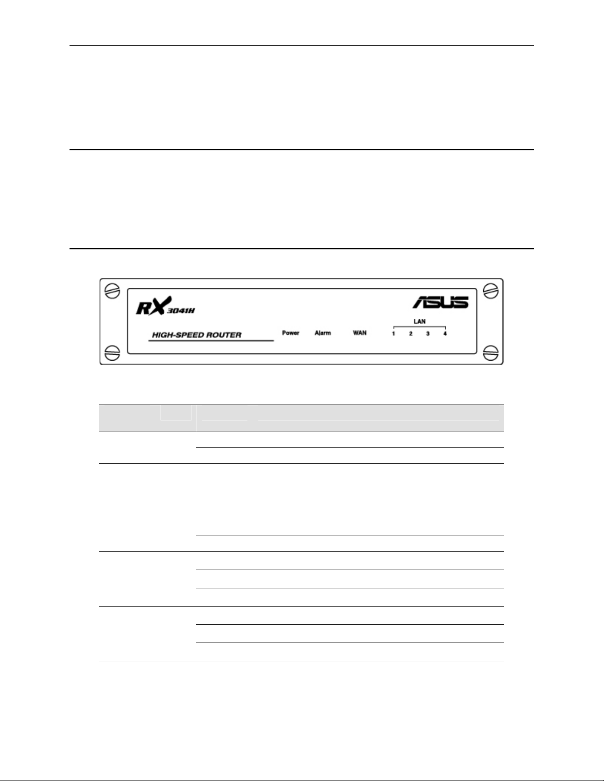
2.2 Front Panel
The front panel contains LED indicators th at show the status of the u nit.
LED
Label
POWER
ALARM
WAN
LAN1 –
LAN4
Figure 2.1. Front Panel LEDs
Table 2.1. Front Panel Label an d LEDs
Color Status Indication
Green
Green
Green
Green
On Unit is powered on
Off Unit is powered off
System malfunctioned if this LED stays on. Note that the
LED is lit during system bo oting a nd is turn ed off
On
Off System functions normally.
On
Flashing
Off
On
Flashing
Off
afterwards. This LED is also used along w/ reset bu tton
during system configuration re set. Please refe r to the
section 11.6.1.2 “
Button” for further detail s.
WAN link established and activ e
Data is transmitted or received via WAN connection
No WAN link
LAN link is established
Data is transmitted or received via LAN connection
No LAN link
Reset to Factory Settings Using Reset
3
Page 18
Chapter 2. Getting to Know the RX3041H RX3041H User’s Manual
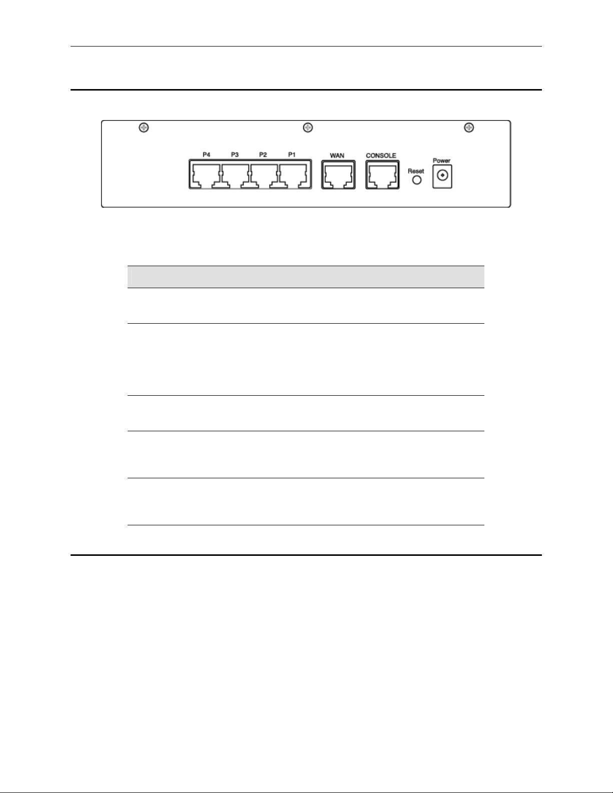
2.3 Rear Panel
The rear panel contains the ports for the unit's data and power connections.
Figure 2.2. Rear Panel Connecti ons
Table 2.2. Rear Panel Labels and LEDs
Label Function
POWER
Reset
CONSOLE
WAN
P1 – P4
Power Input Jack
Connects to the supplied AC adapter
Reset Button
1. Reboots the device
2. Used for resetting the syst em co nfigurati on to th e facto ry
settings. Please refer to the section 11.6.1.2 “
Settings Using Reset Button
Console Port
For ASUSTeK internal use only.
WAN Port
Connects to your WAN device, such as an ADSL or a cable
modem.
LAN Ports
Connects to your PC's Ethernet port, or to the uplink port on the
hub or the switch
2.4 Major Features
2.4.1 Firewall and NAT Features
Reset to Factory
” for further details.
The firewall implemented in your router provid es the following feature s to protect your network fro m being
attacked and to prevent your network from being used as the springboard for attacks.
Address Sharing and Management
Packet Fi ltering
Stateful Packet Inspection
Defense agai nst Denial of Servi ce Attacks
Applicati on Content Filterin g
Log and Alert
Remote Access
4
Page 19
RX3041H User’s Manual Chapter 2 Getting to Know the RX3041H
Keyword ba sed URL Filterin g
2.4.1.1 Address Sharing and Management
The RX3041H Firewall provides NAT to share a single high-speed Internet connection and to save the cost of
multiple connections required for the hosts on the LAN segments connected to the RX3041H. This feature
conceals network address and prevents them from becoming public. It maps unregistered IP addresses of
hosts connected to the LAN with valid ones for Internet access. The RX3041H Firewall also provides reverse
NAT capability, which enables SOHO users to host various servi ces such as e-m ail servers, web servers, et c.
The NAT rules drive the translation mechani sm at the NAT router. T he followin g types of NAT are sup ported
by the RX3041H.
Static NAT – Maps an internal host address to a globally valid Internet address (one-to-one). All
packets are directly translated with t he inf ormation co ntaine d in the map.
Dynamic NAT – Maps an internal host address dynamically to a globally valid Internet address (m-to-
n). The map usually contains a pool of internal IP addresses (m) and a p ool of glo bally valid I nternet I P
addresses (n) with m usually greater than n. Each internal IP address is mapped to one external IP
address on a first come first serve basis.
NAPT (Network Address and Port Translation) – Also called IP Masquerading. Maps many internal
hosts to only one globally v alid Internet addre ss. The m ap usua lly contain s a pool of network p orts to
be used for translation. Every packet is tran slated with the globally val id Internet address; the port
number is translated with a free pool from the pool of net work ports.
Reverse Static – This is inbound mapping that maps a globally valid Internet address to an internal
host address. All packets coming to that external address are relayed to the internal address. This is
useful when hosting services in an internal machin e.
Reverse NAP T – Also called inbo und mapp ing, port mapping, and virt ual serv er. Any packet coming
to the router can be relayed to the internal host based on the protoc ol, port number or IP Addres s
specified in the rule. This is useful when multiple service s are hosted on different int ernal machines.
Note
Appendix A “ALG Configuration” on.
2.4.1.2 ACL (Access Control List)
For a complete listing of all NAT ALGs supported, refer to
ACL rule is one of the basic buil ding blo cks for net work secu rity. Fire wall monito rs each i ndividua l packet,
decodes the header information of inbound and outbound traffic and then either blocks the packet from
passing or allows it to pass based on the contents of the source address, destination address, source port,
destination port, protocol and ot her criteri on, e.g. applicat ion filter, ti me ranges, d efined in t he ACL rules.
ACL is a very appropriate measure for providing isolat ion of one subnet from another. It can be u sed as the
first line of defense in the network to block inbound packets of specific type s from ev er reaching t he prote cted
network.
The RX3041H Firewall’s ACL methodology supports:
Filtering based on destination and source IP address, port number and protocol
Use of the wild card fo r compos ing filter ru les
Filter Rule priorities
Time based filt ers
Applicati on specific filters
User group based f ilters for remote acce ss
2.4.1.3 Stateful Packet Inspection
The RX3041H Firewall uses “stateful packet inspection” that extracts state-related information required for the
security decision from the packet and mainta ins this info rmation for ev aluating subs equent conne ction
attempts. It has awareness of application and creates dynamic sessions that allow dynamic connections so
5
Page 20

Chapter 2. Getting to Know the RX3041H RX3041H User’s Manual
that no ports need to be opened other than the required ones. This provides a solution which is highly secure
and that offers scalability and extensibility.
2.4.1.4 Defense against DoS Attacks
The RX3041H Firewall has an Attack Defense Engine that protects internal networks from known types of
Internet attacks. It provides automatic prote ction from Denial of Servic e (DoS) attacks such a s SYN flooding,
IP smurfing, LAND, Ping of Death and all re-assembly attacks. It can drop ICMP redirects and IP loose/strict
source routing packets. For example, the RX3041H Firewall provides protection from “WinNuke”, a widely
used program to remotely crash unprotected Windows systems in the Internet. The RX3041H Firewall also
provides protection from a variety of common Internet atta cks su ch a s IP Spoofi ng, Ping of Death, Land Att a ck,
Reassembly and SYN flooding.
The type of attack protections provided by the RX304 1H are listed in Table 2. 3.
Table 2.3. DoS Attacks
Type of Attack Name of Attacks
Re-assembly attacks
Bonk, Boink, Teardrop (New Tear),
Overdrop, Opentear, Syndrop, Jolt
ICMP Attacks Ping of Death, Smurf, Twinge
Flooders
Port Scans
TCP Attacks
ICMP Flooder, UDP Flooder, SYN
Flooder
TCP XMAS Scan, TCP Null Scan
TCP SYN Scan, TCP Stealth Scan
TCP sequence number prediction, TCP
out-of sequence attacks
Protection with PF Rules Echo-Chargen, Ascend Kill
IP Spoofing, LAND, Targa, Tentacle
Miscellaneous Attacks
MIME Flood, Winnuke, FTP Bounce, IP
unaligned time stamp attack
2.4.1.5 Application Command Filtering
The RX3041H Firewall allows network administrators to block, monitor, and report on network users access to
non-business and objectionable content. This high-performance content access control results in increased
productivity, lower bandwidth usage and reduced legal liability.
The RX3041H Firewall has the ability to handle active content filtering on certain application protocols such as
HTTP, FTP, SMTP and RPC.
HTTP – You can define HTT P extension based filteri ng schemes for bl ocking
ActiveX
Java Archive
Java Applet s
Microsoft Archives
URLs based on file extensions.
FTP – allows you to def ine and enfo rce the file transf er policy for t he site or group of users
SMTP – allows you to filter operations such as VRFY, EXPN, etc. which reveal excess information
about the recipient.
RPC – allo ws you to filter prog rams based on the assigned RPC p rogram num bers.
6
Page 21

RX3041H User’s Manual Chapter 2 Getting to Know the RX3041H
2.4.1.6 Application Level Gateway (ALG)
Applications such as FTP, games etc., open connectio ns dynamically base d on the respective appl ication
parameter. To go through the firewall on the RX3041H, packets pertaining to an application, require a
corresponding allow rule. In the absence of such rules, the packets will be dropped by the RX3041H Firewall.
As it is not feasible to create policies for numerous applications dynamically (at the same time without
compromising security), intelligence in the form of Application Level Gateways (ALG), is built to parse packets
for applications and open dynamic associations. The RX3041H Firewall provides a number of ALGs for
popular applications such as FTP, H.323, RTSP, Microsoft Games, SIP, etc.
2.4.1.7 URL Filtering
A set of keywords that should not appear in the URL (Uniform Resource Locator, e.g. www.yahoo.com) can be
defined. Any URL containing one or more of these keywords will be bl ocked. This is a pol icy independent
feature i.e. it cannot be associated to ACL rules. T his feature can be in dependently enabled or disabl ed, but
works only if firewall is enabled.
2.4.1.8 Log and Alerts
Events in the network, that could be attempts to affect its security, are record ed in the RX3041 H System log
file. Event details are recorded in WELF (WebTrends Enhanced Log Format ) format so that statistical tools
can be used to generate custom reports. The RX3041H Firewall can also forward Syslog information to a
Syslog server on a private network.
The RX3041H Firewall supports:
Alerts sent t o the a dministrat or via e-mai l.
Maintai ns at a minimum, log detai ls such as, time of packet arriv al, description of a ction taken by
Firewall and reason for action.
Supports the UNIX Syslog format.
Sends log report e-mails as scheduled by the network administrator or by default when the log file is
full.
All the messages a re sent in the WELF format.
ICMP logging to sh ow code and type.
2.4.1.9 Remote Access
The RX3041H Firewall allows the network administrator to segregate the user community into Access Policies
per group. A user can log in using the login page (Refer to “User Login Process” on page 67). After a user is
authenticated successfully, the RX3041H Firewall dynamically activates the user-group’s set of access policies.
These policies will subsequently be enforced until the user logs out of the session or until inactivity timeout
period has lapsed.
7
Page 22

Page 23
RX3041H User’s Manual Chapter 3. Quick Start Guide
3 Quick Start Guide
This Quick Start Guide provides basic instructions for connecting your router to a computer or a LAN and to
the Internet.
Part 1 provides instructions to set up the hardware.
Part 2 describes how to configure Internet properties on your computer(s).
Part 3 shows you how to configure basic settings on the RX3041H to get your LAN connected to the
Internet.
After setting up and configuring your router, you can follow the instructions on page 20 to verify that it is
working properly.
This Quick Start Guide assumes that y ou have already establi shed ADSL o r cable modem serv ice with your
Internet service provider (ISP). These instructions provide a basic configuration that should be compatible with
your home or small office network setup. Refer to the subs equent chapters for addit ional confi guration
instructions.
3.1 Part 1 — Connecting the Hardware
In Part 1, you connect the device to an ADSL or a cable modem (which in turn is connected to a phone jack or
a cable outlet), the power outlet, and your comput er or networ k.
Before you begin, turn the power off for all devices. These
include your computer(s), your LAN hub/ switch (if appli cable),
WARNING
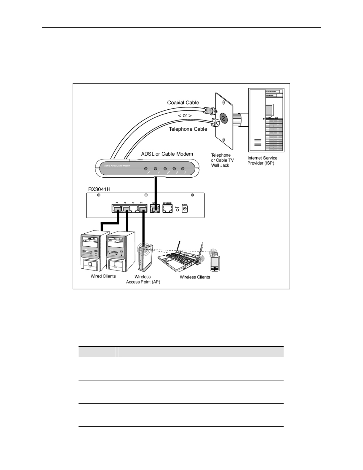
Figure 3.1 illustrates the hardware connections. Please follow the steps that follow for specific instructions.
and the router.
3.1.1 Step 1. Connect an ADSL or a cable modem.
For the RX3041H: Connect one end of the Ethernet cable to the port labe led WAN on the rea r panel of the
device. Connect the other en d to the Et hernet port on th e ADSL or cable mod em.
3.1.2 Step 2. Connect computers or a LAN.
If your LAN has no more than 4 computers, you can use an Ethernet cable to connect computers directly to
the built-in switch on the device. Note that you should atta ch one end of the Ethernet cable t o any of the port
labeled LAN1 – LAN4 on the rear panel of the device and connect the other end to the Ethernet port of a
computer.
If your LAN has more than 4 computers, you can attach one end of an Ethe rnet cable to a hub or a swit ch
(probably an uplink port; plea se refer to t he hu b or switch d ocument ations fo r inst ructions) and the other to th e
Ethernet switch port (labeled LAN1 – LAN4) on the RX3041H.
Note that either the crossover or straight-through Ethernet cable can be used to connect the built-in switch and
computers, hubs or switches as the built-in switch is smart enough to make connections with either type of
cables.
3.1.3 Step 3. Attach the AC adapter.
Connect the AC adapter to the POWER input jack on the rear panel of your router and plug the adapter to a
power outlet or a power strip.
9
Page 24
Chapter 3. Quick Start Guide RX3041H User’s Manual
3.1.4 Step 4 – Power up devices.
Turn on the RX3041H, the ADSL or cable modem and power up your computers.
Press the Power switch on the rear panel of the RX3041H to the ON position. Tu rn on your ADSL or cabl e
modem. Turn on and boot up your computer(s) and any LAN devi ces such as hubs o r switches.
Figure 3.1. Overview of Hardware Connections
You should verify that the LEDs are illuminated as indica ted in Table 3.1. If the LEDs ill uminate as expe cted,
the RX3041H is working properly.
Table 3.1. LED Indicators
This LED: ...should be:
POWER
Solid green to indicate that the device is turned on. If this light
is not on, check if the AC adapter is attached to the RX3041H
and if it is plugged into a po wer sou rce.
LAN1 –
LAN4
Solid green to indicate that the device can communicate with
your LAN or flashing when the device is sending or receiving
data to/from your LAN com puter.
WAN
Solid green to indicate that the device has successfully
established a connection with your ISP or flashing when the
device is sending or receiving data to/from the Internet.
10
Page 25
RX3041H User’s Manual Chapter 3. Quick Start Guide
3.2 Part 2 — Configuring Your Computers
Part 2 of the Quick Start Guide provides instru ctions fo r configuring t he Internet set tings on your comput ers to
work with the RX3041H.
3.2.1 Before you begin
By default, the RX3041H automatically assigns all required Internet settings to your PCs. You need only to
configure the PCs to accept the inf ormatio n whe n it is assi gned.
In some cases, you may want to configure network se ttings
manually to some or all of your computers rather than allow the
Note
If you have co nnected y our PC via Et hernet to t he RX30 41H, follo w the in struction s that corre spond to
the operating system installed on you r PC.
3.2.2 Windows[CT6]® XP PCs:
1. In the Windows task bar, click the <Start> button, and then click Control Panel.
RX3041H to do so. See “Assigning static IP addresses to your PCs”
in page 13 for instructions.
2. Double-click the Net work Connections icon.
3. In the LAN or High-Speed Internet window, right-click on icon corresponding to your network
interface card (NIC) and select Properties. (Often this icon is labeled Local Area Connection).
The Local Area Connection dialog box displ ays with a list of currently in stalled net work items.
4. Ensure that the check box to the left of the item labeled Internet Protocol T CP/IP is che c ked, and
click <Properties> button.
5. In the Internet Protocol (TCP/IP) Properties dial og box, click the radio button labeled Obtain an
IP address automatically. Also click the radio button labeled Obtain DNS server address
automatically.
6. Click <OK> button twice to confirm your changes, and close the Control Panel.
3.2.3 Windows® 2000 PCs:
First, check for the IP protocol and, if n ecessary, in stall it:
1. In the Windows task bar, click the <Start> button, point to Settings, and then click Control Panel.
2. Double-click the Network and Dial-up Connections icon.
3. In the Network and Dial-up Conn ections window, right-click the Local Area Connection icon,
and then select Properties.
The Local Area Connection Properties dialog box displays a list of currently installed network
components. If the list includes Internet Protocol (TCP/IP), then the protocol has already been
enabled. Skip to step 10.
4. If Internet Protocol (TCP/IP) does not display as an installed component, click <Install> button.
5. In the Select Network Component Type dialog box, select Protocol, and then click <Add> button.
6. Select Internet Protocol (TCP/IP) in the Network Protocols list, and then click <OK> button.
You may be prompted to install files from your Windows 2000 installation CD or other media. Follow
the instructions to install t he files.
11
Page 26

Chapter 3. Quick Start Guide RX3041H User’s Manual
7. If prompted, click <OK> button to restart your computer with the new settings.
Next, configure the PCs to accept IP addresses assigned by the RX3041H:
8. In the Control Panel, double-click the Network and Dial-up Connections icon.
9. In Network and Dial-up Co nnections window, right-click the Local Area Connection icon, and
then select Properties.
10. In the Local Area Connection Properties dialog box, select Internet Protocol (TCP/IP), and then
click <Properties> button.
11. In the Internet Protocol (TCP/IP) Properties dialog box, click the radio button labeled Obtain an
IP address automatically. Also click the radio button labeled Obtain DNS server address
automatically.
12. Click <OK> button twice to confirm and save your changes, and then close the Control Panel.
3.2.4 Windows® 95, 98, and Me PCs
1. In the Windows task bar, click the <Start> button, point to Settings, and then click Control Panel.
2. Double-click the Network icon.
In the Network dialog box, look for an entry st arted w/ “TCP/IP ->” and the name of you r network
adapter, and then click <Properties> button. You may have to scroll down the list to find this entry.
If the list includes such an entry, then the TCP/IP protocol has already been enabled. Skip to step 8.
3. If Internet Protocol (TCP/IP) does not display as an installed component, click <Add> button.
4. In the Select Network Component Type dialog box, select Protocol, and then click <Add> button.
5. Select Microsoft in the Manufacturers list box, and then click TCP/IP in the Network Protocols list,
box and then click <OK> button.
You may be prompted to install files from your Windows 95, 98 or Me insta llation CD or other me dia.
Follow the instructions to install the files.
6. If prompted, click <OK> button to restart your computer with the new settings.
Next, configure the PCs to accept IP i nformatio n assigned by the RX 3041H:
7. In the Control Panel, double-click the Ne twork icon.
8. In the Network dialog box, select an entry started with “TCP/IP ->” and the name of your network
adapter, and then click <Properties> button.
9. In the TCP/IP Properties dialog box, click the radio bu tton labeled Obtain an IP address
automatically.
10. In the TCP/IP Properties dialog box, click the “Default Gateway” tab. Enter 192.168.1.1 (the
default LAN port IP address of the RX3041H) in the “New gateway” address field and click
<Add> button to add the default gateway entry.
11. Click <OK> button twice to confirm and save your changes, and then close the Control Panel.
12. If prompted to restart your computer, click <OK> button to do so with the new settings.
3.2.5 Windows® NT 4.0 workstations:
First, check for the IP protoc ol and, if n ecessary, in stall it:
1. In the Windows NT task bar, click the <Start> button, point to Settings, and then click Control
Panel.
12
Page 27
RX3041H User’s Manual Chapter 3. Quick Start Guide
2. In the Control Panel window, double cli c k the Network icon.
3. In the Network dialog box, click the Protocols tab.
The Protocols tab displays a list of currently in stalle d network protocol s. If the li st includes TCP/IP
Protocol, then the protocol has already been enabled. Skip to step 9.
4. If TCP/IP does not display as an installed component, click <Add> button.
5. In the Select Network Protocol dialog box, select TCP/IP, and then click <OK> button.
You may be prompted to install files from your Windows NT installat ion CD or other media. Fol low
the instructions to install t he files.
After all files are installed, a window displays to inform you that a TCP/IP service called DHCP can
be set up to dynamically assign IP information.
6. Click <Yes> button to continue, and then click <OK> button if prompted to restart your computer.
Next, configure the PCs to accept IP addresses assigned by the RX3041H:
7. Open the Control Panel window, and then double-click the Network icon.
8. In the Network dialog box, click the Protocols tab.
9. In the Protocols tab, select TCP/IP, and then click <Properties> button.
10. In the Microsoft TCP/IP Properties dialog box, click the radio button labeled Obtain an IP
address from a DHCP server.
11. Click <OK> button twice to confirm and save your changes, and then close the Control Panel.
3.2.6 Assigning static IP addresses to your PCs
In some cases, you may want to assign IP addresses to some or all of your PCs di rectly (often called
“statically”), rather than allowing the RX3041H to assign them. This option may be desirable (but not required)
if:
You have o btained one or mo re public IP addresse s that you want to al ways associat e with specific
computers (for example, if you are using a computer as a public web server).
You maintain different subnets on your LAN.
However, during the first time co nfigurati on of your RX3041H, you must assign an IP address in the
192.168.1.0 network for your PC, say 192.168.1.2, in order to establish connection between the RX3041H and
your PC as the default LAN IP on RX3041H i s pre-confi gured a s 192.16 8.1.1. Ent er 255. 255.25 5.0 for t he
subnet mask and 192.168.1. 1 for the d efault gat eway. T hese setting s may be ch anged lat er to refle ct your true
network environment.
On each PC to which you want to assign static information, follow the instructions on pages 11 through 12
relating only to checking fo r and/or instal ling th e IP protoco l. Once it is i nstall ed, conti nue to foll ow the
instructions for displaying each of the Internet Prot ocol (TCP/IP) properties. Instead of enabling dynamic
assignment of the IP addresse s for the computer, DNS serv er, and default gat eway, cl ick the radio buttons th at
enable you to enter the informatio n manually.
Your PCs must have IP addresses that place them in the same
subnet as the router’s LAN port. If you manually assign IP
Note
addresses to all your LAN PCs, you can fo llow the i nstructi ons in
Chapter 5 to change the router’s LAN port IP address accordingly.
3.3 Part 3 — Quick Configuration of Your Router
In Part 3, you log into the Configuration Manager o n the router and conf igure basic settin gs for your Internet
connection. Your ISP should provide you with the necessary information to complete this step. Note the intent
13
Page 28
Chapter 3. Quick Start Guide RX3041H User’s Manual
here is to quickly get the router up and running, instructions are concise. You may refer to corresponding
chapters for more details.
3.3.1 Buttons Used in Setup Wizard
The RX3041H provides a preinstalled software program called Configuration Manager that enables you to
configure the RX3041H via your Web browser. The settings that you are most likely to need to change before
using the device are grouped onto sequence of configuration pages guided by Setup Wizard. The following
table shows the buttons that you’ll encounter in Setup Wizard.
Button Function
Click this button to save the information and proceed to the next
configuration page.
Click this button to go back to the previous confi guration page.
3.3.2 Setting Up the RX3041H
Follow these instructions to setup the RX3041H:
1. Before accessing the Configuration Manager in the RX3041 H, make sure that the HTTP proxy
setting is disabled in your browser. In IE, click “Tools” Î “Internet Options…” Î
“Connections” tab Î “LAN settings…” and then uncheck “Use proxy server for your LAN …”
2. On any PC connected to one of the four LAN ports on the RX3041H, open your Web browser,
and type the following URL in the address/location box, and press <Enter>:
http://192.168.1.1
This is the predefined IP address for the LAN port on the RX3041H.
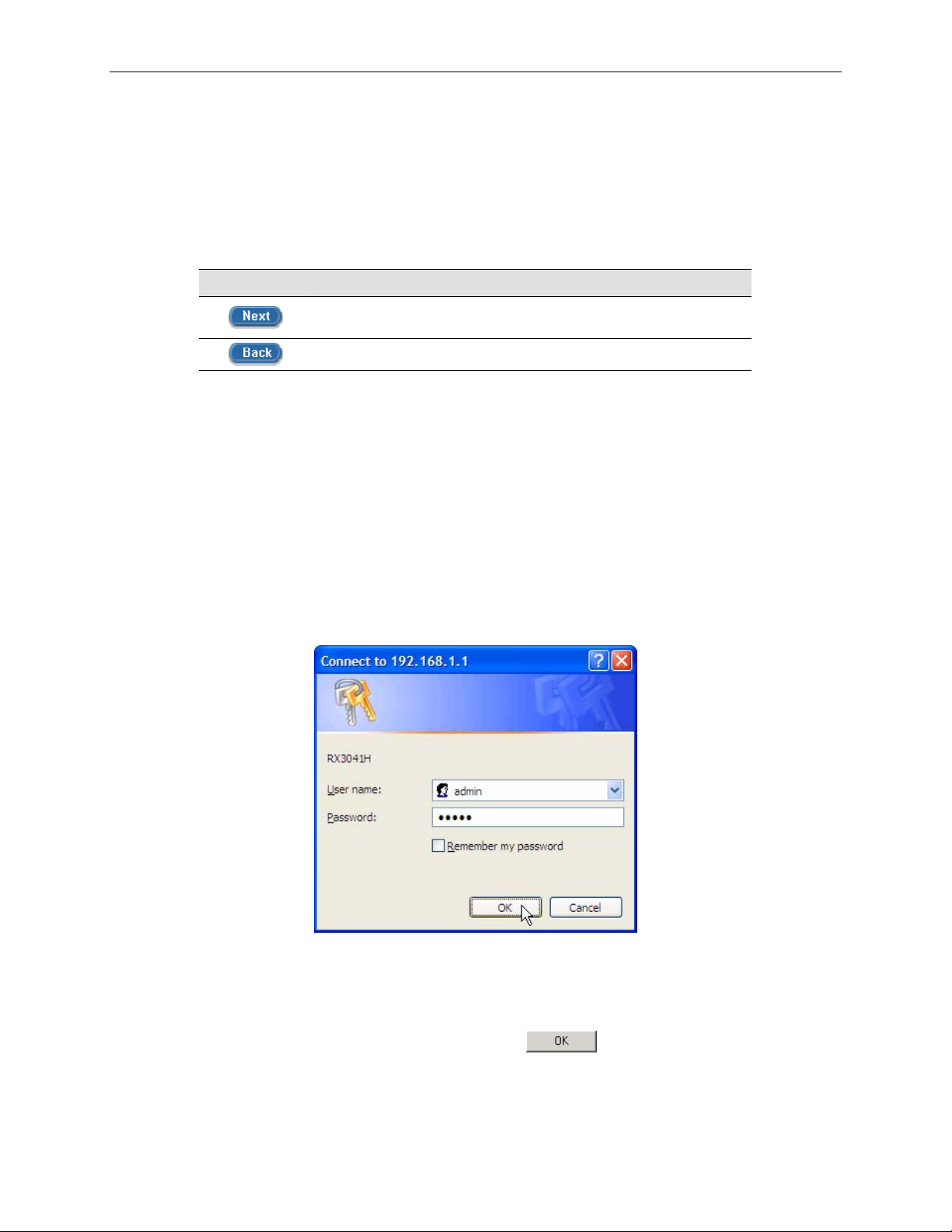
A login screen displays, as shown in Figure 3.2.
Figure 3.2. Login Screen
If you have problem connecting to the RX3041H, you may want to check if your PC is configured to
accept IP address assignment from the RX3041H. Another method is to set the IP address of your PC
to any IP address in the 192.168.1.0 network, such as 192.1 68.1.2.
3. Enter your user name and password, and then click
Manager. The first time you log into this program, use these defaults:
Default User Name:
14
admin
to enter the Configuration
Page 29
RX3041H User’s Manual Chapter 3. Quick Start Guide
admin
Default Password:
You can change the password at any time (see section 11.2
Note
Change the Login Password on page 93).
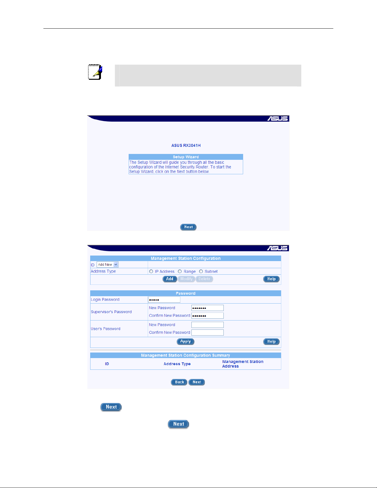
The Setup Wizard home page di splays ea ch time you log into t he Con figuration M anage r (show n in
Figure 3.3 on page 15).
Figure 3.3. Setup Wizard Home Pa ge
Figure 3.4. Setup Wizard – Passwor d Configura tion Page
4. Click on the
button to enter the password configuration page as shown in Figure 3.4.
Change the password in the spaces provided if desired. Otherwise, proceed to the next
configuration page by clicking on the
15
button.
Page 30
Chapter 3. Quick Start Guide RX3041H User’s Manual
When changing passwords, make sure you enter the existing login password in the Login Password
field, make any changes for the passwords and click the
button to save the changes.
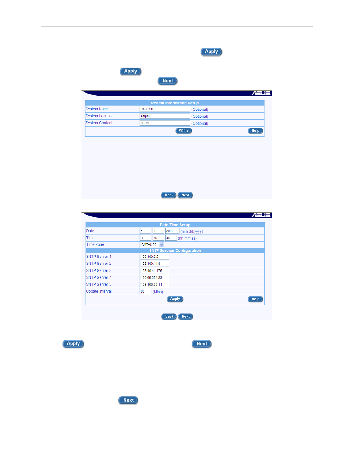
5. Now we are at the System Information se tup page; enter the requested information in the spaces
provided and click the
configuration page by clicking on the
button to save the changes. Otherwise, proceed to the next
button.
Figure 3.5. Setup Wizard – System Identity Configuration Page
Figure 3.6. Setup Wizard – Date/Time Configuration Pag e
6. Set the time zone for your router by selecting one from the Time Zone drop -down list. Click
to save the settings and then click on the button to go to the next configuration
page.
There is no real time clock inside the router. The syst em date and time may be mainta ined by external
time servers. There is no need to set the date and time here unless you don’t hav e access to a time
server and you want the router to maintain its own time.
7. It is recommended that you keep the default LAN IP settings for now until after you have
completed the rest of the configurations and confirm that your Internet connection is working
properly. Click on the
16
button to proceed to the next configuration page.
Page 31

RX3041H User’s Manual Chapter 3. Quick Start Guide
Figure 3.7. Setup Wizard – LAN IP Configura tion Page
Figure 3.8. Setup Wizard – LAN DHCP Server Configuration Page
8. It is recommended that you keep the default settings for the DHCP server until after you have
completed the rest of the configurations and confirm that your Internet connection is working
properly. Click on the
button to proceed to the next configuration page.
9. Now we are at the last page of the Setup Wizard, which is to configure the WAN settings for the
router. Depending on the connection mode required for your ISP, select one from the Connection
Mode drop-down list (see Figure 3.9): PPPoE, Dynamic and Static. PPPoE is usually used by
ADSL service providers and Dynamic connection mode is used by most cable modem service
providers.
17
Page 32

Chapter 3. Quick Start Guide RX3041H User’s Manual
Connection
Mode dropdown list
Figure 3.9. Setup Wizard – WAN PPPoE Configuration Page
Connection
Mode dropdown list
18
Figure 3.10. Setup Wizard – WAN Dynamic IP Configuration Page
Page 33

RX3041H User’s Manual Chapter 3. Quick Start Guide
a) PPPoE Connection Mode (see Figure 3.9)
• You don’t need to enter primary/secondary DNS IP addresses as PPPoE is able to
automatically obtain this information for you from your ISP. However, if you prefer to use
your favorite DNS servers, you may enter them in the space provided.
• Host name is optional. You may leave it empty if your ISP did not provide such
information.
• Enter the user name and password provided by your ISP.
• Click on
button to save the PPPoE settings.
b) Dynamic IP Connection Mode (see Figure 3.10)
• You don’t need to enter primary/se condary DNS IP addresses as DHCP client is able to
automatically obtain this information for you from your ISP. However, if you prefer to use
your favorite DNS servers, you may enter them in the space provided.
• Host name is optional. You may leave it empty if your ISP did not provide such
information.
• If you had previously registered a specific MAC address with your ISP for Internet
connections, enter the registered MAC address here and make sure you check th e MAC
cloning check box.
• Click on
button to save the dynamic IP settings.
Connection
Mode dropdown list
Figure 3.11. Setup Wizard – WAN Static IP Configuration Page
c) Static IP Connection Mode
• Enter WAN IP address in the IP Address field. This information should be provided by
your ISP.
19
Page 34

Chapter 3. Quick Start Guide RX3041H User’s Manual
• Enter Subnet Mask for the WAN. This information should be provided by your ISP.
Typically, it is 255.255.255.0.
• Enter gateway address provided by your ISP in the space provided.
• Enter at lease the primary DNS IP address provided by your ISP. Secondary DNS IP
address is optional. Enter it in the space provided if you have such information from your
ISP.
• Click
You have now completed customizing basic conf iguratio n settings. Read th e following se ction to determine if
you have access to the Internet.
to save the static IP settings
3.3.3 Testing Your Setup
At this point, the RX3041H shoul d enable any comp uter on yo ur LAN t o use t he RX3 041H’s A DSL or ca ble
modem connection to access the Internet.
To test the Internet connection, open your web browser, an d type the URL of any external webs ite (such as
http://www.asus.com). The LED labeled WAN shoul d be blinking ra pidly and may app ear solid as the device
connects to the site. You should also be able to browse the web site through your web browser.
If the LEDs do not illuminate as expected or the web page does not display, see Appendix D for
troubleshooting suggestions.
3.3.4 Default Router Settings
In addition to handling the DSL connection to your ISP, the router provides a variety of services to your
network. The device is pre-configured wit h default setti ngs for use with a typical h ome or small office net work.
Table 3.2 lists some of the most important default setting s; these and othe r features are describ ed fully in the
subsequent chapters. For a complete list of default settings, please refer to the section B.2 “Default Settings”. If
you are familiar with network configuration setting s, review the settings in Tabl e 3.2 to verify that they meet the
needs of your network. Follow the instructions to change them if necessary. If you are unfamiliar with these
settings, try using the device with out modif ication.
Before modifying any settings, review Chapter 4 for general information about accessing and using the
Configuration Manager.
Table 3.2.
Option Default Setting Explanation/Instructions
DHCP (Dynamic
Host
Configuration
Protocol)
LAN Port IP
Address
20
DHCP server enabled with the
following pool of addresses:
192.168.1.10 through 192. 168.1. 200
Static IP address: 192.168.1.1
subnet mask: 255.255.255. 0
Default Settings Summary
The router maintains a pool of private IP
addresses for dynamic assignment to your
LAN computers. To use thi s service, you
must have set up your computers to
accept IP information dynamically, a s
described in Part 2 of the Quick Start
Guide. See section 5.2 for a n expla nation
of the DHCP service.
This is the IP address of the LA N port on
the RX3041H. The LAN port connects the
device to your Ethernet network. Ty pically,
you will not need to change this address.
See section 5.1 LAN IP Addre ss for
instructions.
Page 35

RX3041H User’s Manual Chapter 4. Getting Started with the Configuration Manager
4 Getting Started with the Configuration
Manager
Your router includes a preinstalled program called the Configuration Manager, which allows you to customiz e
the device settings to meet the needs of your network. You access the Config uration Manager th rough a web
browser from any PC that has access to the router via network connections.
This chapter describes the general guidelines for using the Configurati on Manag er.
[CT9]
4.1 Log into the Configuration Manager
To access the Configuration Manager, you need the following:
A computer that has access to the router via network connections as described in the Quick Start
Guide chapter.
A web browser on your computer. Configuration Manager is compatible with Microsoft Internet
Explorer® 5.5, Netscape 7.0 .2 or newe r.
Although you may log into the Configuration Manager from any compute r that can reach your router via the
LAN or WAN connections, the instructions provided here assumes that your computer is connected to the LAN
port of your router.
1. From a LAN computer, open your web browser, type the following in the web address (or location)
box, and press <Enter>:
http://192.168.1.
This is the predefined IP address f or the L AN port of your ro uter. A logi n screen display s, as shown in
Figure 4.1.
1
Figure 4.1. Configuration Manager Login Screen
2. Enter your user name and password, and then click
The first time you log into the program, use the se defaul ts:
Default User Name:
Default Password:
21
admin
admin
button.
Page 36

Chapter 4. Getting Started with the Configuration M anager RX3041H User’s Manual
You can change the password at any time (see section 11.2. 1
Note
The Setup Wizard page, as shown i n Figure 3. 3, disp lays each ti me you log int o the Conf iguratio n
Manager.
Change the Login Password on page 93).
4.2 Functional Layout
Typical Configuration Manager page consists of two separate frames. The left frame, as shown in Figure 4.2,
contains all the menus avail able fo r device config uration. Men us are i ndicat ed by fil e icons,
menus are grouped into categorie s, such as LAN, WA N and etc., and indicate d by folder icons,
depending on whether the group of menu s are expanded or not. You can cli ck on any of these to display a
specific configuration page.
, and related
or ,
Setup Menu Frame
Configuration Frame
Figure 4.2. Typical Configur ation Man ager Pag e
A separate page displays in the right-hand -side fram e for each menu. For exa mple, the confi guration pag e
displayed in Figure 4.2 is inten ded for DHCP config uration.
4.2.1 Setup Menu Navigation Tips
To expand a grou p of related menus: cl ick on the + sign next to the corre sponding file folde r icon, .
To contract a group of related menus: click on the – sign next to the “opened” file folder icon,
To open a specifi c configurat ion pa ge, click on t he file ico ns,
, next to the desired menu item.
.
4.2.2 Commonly Used Buttons and Icons
The following buttons or icon s are used th rougho ut the appl ication. T he follo wing ta ble descri bes the fu nction
for each button or icon.
22
Page 37

RX3041H User’s Manual Chapter 4. Getting Started with the Configuration Manager
Table 4.1. Description of Commonly Used Buttons an d Icons
Button/Icon Function
Stores any changes you have made on the current page.
Adds the existing configuration to the sy stem, e.g. a stat ic route
or a firewall ACL rule and etc.
Modifies the existing configuration in t he system, e.g. a static
route or a firewall ACL rule and etc.
Deletes the selected item, e.g. a static rout e or a firewall ACL rule
and etc.
Launches the online help for the current topic in a separate
browser window. Help is available from any main topic page.
Redisplays the current page with updated statistics or settings.
Selects the item for editi ng.
Deletes the selected ite m.
4.3 Overview of System Configuration
To view the overall system conf igurat ion, open the System Info page by clicking the System Info menu. Figure
4.3 shows the information availa ble in the System Inf o page.
Figure 4.3. System Information Page
23
Page 38

Page 39

RX3041H User’s Manual Chapter 5. Configuring LAN Settings
5 Configuring LAN Settings
This chapter describes how to configure LAN properties for the LAN interface on the RX3041H that
communicates with your LAN computers. You’ll learn to configure IP address, DHCP and DNS server for your
LAN in this chapter.
5.1 LAN IP Address
If you are using the RX3041H with multiple PCs on your LAN, you must connect the LAN via the Ethernet
ports on the built-in Ethernet switch. Y ou must assign a uniqu e IP address t o each device re sidin g on your
LAN. The LAN IP address identifies the RX3041H as a node on your network must be in the same subnet as
the PCs on your LAN. The default LAN IP for the RX3041H is 192.168.1.1.
A network node can be thought of as any interface where a
device connects to the network, such as the RX3041H’ s LAN port
Definition
and the network interface cards on your PCs. See Appendix A for
an explanation of subnets.
You can change the default to reflect t he true IP a ddress that y ou want to use wit h your n etwork.
The RX3041H itself can function as a DHCP server for your LAN
computers, as described in section 5.2.2, but not for its own
Note
LAN port.
5.1.1 LAN IP Configuration Parameters
Table 5.1describes the confi gurati on para meter s availa ble for LAN IP conf igurat ion.
Table 5.1. LAN IP Configuration Par ameters
Setting
IP Address
Subnet Mask
Description
The LAN IP address of the RX3041H. This IP is used by your computers to
identify the RX3041H’s LAN port. Note that the public IP address assigned to
you by your ISP is not your LAN IP address. The public IP address identifies
the WAN port on the RX3041H to the Internet.
The LAN subnet mask identifies which parts of the LAN IP Address refer to
your network as a whole and which parts refer specifically to nodes on the
network. Your device is preconf igured wit h a defau lt subnet mask of
255.255.255.0.
5.1.2 Configuring the LAN IP Address
Follow these steps to change the default LAN IP address.
1. Open the LAN configuration page by clicking the LAN Î IP menu.
2. Enter a LAN IP address and subnet mask for the RX3041H in the IP
Address and Subnet Mask fields as shown in Figure 5.1.
25
Page 40

Chapter 5. Configuring LAN Settings RX3041H User’s Manual
Figure 5.1. LAN IP Address Configuration
3. Click.
If you change the LAN IP address, the connection will be terminate d.
4. Reconfigure your PCs, if necessary, so that their IP addresses place them in the same subnet as
the new IP address of the LAN port. See the Quick Start Guide chapter, “Part 2 — Configuring
Your Computers,” for instructions.
5. Log into Configuration Manager by typing the new IP address in your Web browser’s
address/location box.
button to save the LAN IP address.
5.2 DHCP (Dynamic Host Configuration Protocol)
5.2.1 Introduction
5.2.1.1 What is DHCP?
DHCP is a protocol that enables network administ rators to centrally man age the assignment a nd distrib ution of
IP information to computers on a network.
When you enable DHCP on a network, you allow a device — such as the RX3041H — to assign temporary IP
addresses to your computers whenever they connect to your network. The assigning device is called a DHCP
server, and the receiving device is a DHCP client.
If you followed the Quick Sta rt Guide i nstru ction s, you eit her
configured each LAN PC with an IP address, or you specified that
Note
it will receive IP information dynamically (automat ically). If you
chose to have the informati on assign ed dynam ically, t hen you
configured your PCs as DHCP clients that will accept IP
addresses assigned from a DCHP server such as the RX3041H.
The DHCP server draws from a defined pool of IP addresses and “leases” them for a specified amount of time
to your computers when they request an Internet session. It monitors, collects, and redistributes the addresses
as needed.
On a DHCP-enabled network, the IP information is assigned dynamically rather than statically. A DHCP client
can be assigned a different address from the pool each t ime it reconnects to the net work.
5.2.1.2 Why use DHCP?
DHCP allows you to manage and distribute IP addresses throughout your network from the RX3041H. Without
DHCP,
you would have to configure each computer separately with IP address and related information. DHCP
is commonly used with large networks and those that are frequently expanded or otherwise updated.
26
Page 41

RX3041H User’s Manual Chapter 5. Configuring LAN Settings
5.2.2 DHCP Server Configuration
5.2.2.1 DHCP Configuration Parameters
Table 5.2 describes the con figuratio n para meter s availa ble for DHCP servi ce.
Table 5.2. DHCP Server Configuration Parameters
Field Description
IP Address Pool
Begin/End
Subnet Mask
Lease Time
Default Gateway IP
Address
Primary/Secondary
DNS Server IP
Address
Primary/Secondary
WINS Server IP
Address (optional)
Specify the lowest and highest addresses in the DHCP address pool.
Enter the subnet mask to be used for the DHCP address pool.
The amount of time the assigned address will be used by a device connected
on the LAN.
The address of the default gateway for computers that receive IP addresses
from this pool. The default gateway is t he devi ce that the DHCP clie nt
computers first contacted to commu nicate with t he Intern et. Typically , it is t he
RX3041H’s LAN port IP address.
The IP address of the Domain Name System server to be used by computers
that receive IP addresses from this pool. The DNS server translates common
Internet names that you type into your web browser into their equivalent
numeric IP addresses. Typically, the server(s) are located with your ISP.
However, you may enter LAN IP address of the RX3041H as it will serve as
DNS proxy for the LAN computers and fo rward the DNS request from the
LAN to DNS servers and relay the results back to the LAN com puters. Note
that both the primary and secondary DNS servers are optional.
The IP address of the WINS servers to be used by computers that receive IP
addresses from the DHCP IP address pool. You don’t need to enter this
information unless your network has WINS servers.
5.2.2.2 Configuring DHCP Server
By default, the RX3041H is configured as a DHCP server on the
LAN side, with a predefined IP addre ss pool of 1 92.168. 1.10
Note
First, you must configure your PCs to a ccept DHCP inf ormatio n assigned by a
DHCP server:
1. Open the DHCP server configuration page by clicking the LAN Î DH
menu. You will see the existing DHCP server configuration and the IP
lease table when you open the page.
2. Enter the information for the IP Address Pool (Begin/End Address),
Subnet Mask, Lease Time and Default Gateway IP Address fields; others, such as
Primary/Secondary DNS Server IP Address and Primary/Secondary WINS Server IP
Address are optional. However, it is recommended that you enter the primary DNS server IP
address in the space provided. You may enter the LAN IP or your ISP’s DNS IP address in the
primary DNS Server IP Address field. For details of each configuration parameter, please refer to
Table 5.2.
27
through 192.168.1.200 (sub net mask 255.255. 255.0). To ch ange
this range of addresses, follow the procedure s described in this
section.
CP
Page 42

Chapter 5. Configuring LAN Settings RX3041H User’s Manual
Figure 5.2. DHCP Configuration
3. Click
to save the DHCP server configurations.
5.2.2.3 Viewing Existing IP Address Lease
When the RX3041H functions as a DHCP server for your LAN, it keeps a record of all the addresses it has
leased to your computers. To view the existing lease table, just open the DHCP Server confi guration page by
clicking the LAN Î DHCP menu. A lease table similar t o that shown i n Figure 5.3 is di splayed at t he botto m
half of the DHCP configuration page.
Figure 5.3. Sample DHCP Lease Table
The DHCP Server Lease Table shows all the IP addresses that are currently provided to the LAN devices.
Table 5.3 describes the inform ation fo r each of th e paramet ers shown in t he DHCP l ease t able.
Table 5.3. DHCP Address Assignment Param eters
Field Description
MAC Address
Assigned IP Address
IP Address Expired
on
A hardware ID of the device that leases an IP address from the DHCP server.
The address that has been leased from the pool.
The time when the leased address is to be terminated.
5.2.3 Fixed DHCP Lease
Fixed DHCP lease is used in situation when a fixed IP addre ss is desired fo r a host that gets IP from the
DHCP server. First, you should configure your PCs to accept DHCP information as signed by a DHCP server:
5.2.3.1 Fixed DHCP Lease Configuration Parameters
Table 5.4 describes the con figuratio n para meter s availa ble for fix ed DHCP le ase.
28
Page 43

RX3041H User’s Manual Chapter 5. Configuring LAN Settings
Table 5.4. Fixed DHCP Lease Configuration Parameter s
Field Description
Fixed DHCP Lease
MAC
A hardware ID of the device that needs a fixed IP add ress fr om the DHCP
server.
Fixed DHCP Lease IP
The IP address leased from the DHCP server. Note that it is recommended
that this IP address be outside of the DHCP IP pool.
5.2.3.2 Add a Fixed DHCP Lease
To add a fixed DHCP lease, follow the instructions below:
1. Open the Fixed DHCP Lease configuration page by clicking the LAN Î
Fixed DHCP Lease menu.
2. Enter the MAC address and the desired IP address of the host requiring
a fixed IP address. For details of each configuration parameter, please refer to Table 5.4.
Figure 5.4. Fixed DHCP Lease Configuration Page
3. Click on the
button to add the new fixed DHCP lease entry.
5.2.3.3 Delete a Fixed DHCP Lease
To delete a fixed DHCP lease, just click on the icon in front of the specific fixed DHCP l ease.
5.2.3.4 Viewing Fixed DHCP Lease Table
To see existing fixed DHCP lease, just open the Fixed DHCP Lease config uration pag e by clicking the LAN Î
Fixed DHCP Lease menu.
5.3 DNS
5.3.1 About DNS
Domain Name System (DNS) servers map the user-friendly domain names that users type into their Web
browsers (e.g., “www.yahoo.com”) to the equivalent numerical IP addresses that are used for Internet routing.
When a PC user types a domain name into a browser, the PC must first send a request to a DNS serve r to
obtain the equivalent IP add re ss. T h e DNS se rve r wi ll att em pt t o l ook up th e dom ai n na me in it s o wn d at aba se,
and will communicate with higher -level DNS servers whe n the name cannot be found lo cally. When the
address is found, it is sent back to the requesting PC and is referenced in IP packets for the remainder of the
communication.
29
Page 44

Chapter 5. Configuring LAN Settings RX3041H User’s Manual
5.3.2 Assigning DNS Addresses
Multiple DNS addresses are useful to provide alternat ives when one of the serv ers is down or is encount ering
heavy traffic. ISPs typically provide primary and secondary DNS addresses, and may provide additional
addresses. Your LAN PCs learn these DNS addre sses in o ne of the fo llowing way s:
Statically: If your ISP provides you with their DNS server addresses, you can assign them to each PC
by modifying the PCs' IP properties.
Dynamically from a DHCP Se rver: You can configure the DNS a ddresses in the DHCP server in the
RX3041H and allow the DHCP server to distribute the DNS addresses to the PCs. Please refer to the
section 5.2.2.2 for instructions on configu ring DHCP server.
In either case, you can specify the actual addresses of the ISP's DNS servers (on the PC or in the DHCP pool),
or you can specify the address of the LAN port on the RX3041H (e.g., 192.168.1.1). When you specify the
LAN port IP address, the device performs DNS relay, as described in the following section.
Note
If you specify the actual DNS addresses on the PCs or in the
DHCP pool, the DNS relay feature is not used.
5.3.3 Configuring DNS Relay
When you specify the device's LAN port IP address as the DNS address, then the RX3041H automatically
performs “DNS relay”; i.e., because the device itself is not a DNS server, it forwards domain name lookup
requests from the LAN PCs to a DNS server at the ISP. It then relays the DNS server’s response to the PC.
When performing DNS relay, the RX3041H must maintain the IP addresses of the DNS servers it contacts. It
can learn these addresses in either or both of the following ways:
Learned through PPP oE or Dy namic IP Conne ction: If the RX3041H uses a PPPoE (see section
6.2.2 “Configuring PPPoE for WAN”) or Dyna mic IP (see section 6. 3.2 “Configuri ng Dynami c IP for
WAN”) connection to the ISP, the p rimary an d secon dary DNS add resses can be le arned via t he
PPPoE protocol. Using this option provides the advantage that you will not need to reconfigure the
PCs or the RX3041H if the ISP changes their DNS addresses.
Manually configure on the RX3041H: You can also specify the ISP's DNS addresse s in the WA N
configuration page as shown i n Figu re 6.1. WAN PPPo E Configur ation Pag e, Figur e 6.3. WA N
Dynamic IP (DHCP client) Configuration, or Figure 6.5. WAN Static IP Configuration.
Follow these steps to configure DNS relay:
1. Enter LAN IP in the DNS Server IP Address field in DHCP configuration page as shown in Figure
5.2.
2. Configure the LAN PCs to use the IP addresses assigned by the DHCP server on the RX3041H,
or enter the RX3041H's LAN IP address as their DNS server address manually for each PC on
your LAN.
30
Note
DNS addresses that are assigned to LAN PCs prior to enabling
DNS relay will remain in effect until the PC is rebooted. DNS relay
will only take effect when a PC's DNS address is the LAN IP
address.
Similarly, if after enabling DNS relay, you specify a DNS address
(other than the LAN IP address) in a DHCP pool or statically on a
PC, then that address will be used instead of the DNS relay
address.
Page 45

RX3041H User’s Manual Chapter 5. Configuring LAN Settings
5.4 Viewing LAN Statistics
You will not typically need to view the stati stics data for your LA N, but you may find
it helpful when working with your ISP to diagnose network and Internet data
transmission problems.
To view LAN IP statisti cs, open t he LAN Statistics page by cli cking t he LAN Î
Statistics menu. Figure 5.5 shows a sample LAN Statistics.
To see the updated statistics, click on the
Figure 5.5. LAN Statisti cs Page
button.
31
Page 46

Page 47

RX3041H User’s Manual Chapter 6. Configuring WAN Settings
6 Configuring WAN Settings
This chapter describes how to configure WAN settings for the WAN interface on the RX3041H that
communicates with your ISP. You’l l learn to config ure IP add ress, DHCP and DNS se rver for y our WAN in this
chapter.
6.1 WAN Connection Mode
Three modes of WAN connection are supported by the RX3041H – PPPoE, dynamic IP and static IP. The
configuration of each connection mode is descri bed in the details in th e following sectio ns.
6.2 PPPoE
6.2.1 WAN PPPoE Configuration Parameters
Table 6.1describes the configuration parameters available for WAN PPPoE connection mode.
Table 6.1. WAN PPPoE Configuration Parameters
Setting Description
Channel ID
Default Gateway
Unnumbered PPPoE
Host Name
User Name and
Password
Service Name
Access Concentrator
Name
Select the PPPoE channel for this PPPoE session. Note that only two
simultaneous PPPoE channels are supported.
Since more than one PPPoE sessi on may be active at t he same ti me, a
default gateway must be chosen to route packets addressed to net works not
explicitly listed in the routing table. Sel ect from t he drop down li st the int erface
to be used as the default gateway.
Click on the “Enable” or “Disable” radio button to enable or disable this option.
Traditionally, each network interface must have a unique IP add ress.
However, an unnumbered interface does not have to have a unique IP
address. This means that when this option is en abled, the WAN and the LA N
use the same IP address. Network resources are therefore conserved
because fewer network IP addresse s are used an d routing tabl e is smaller.
Enter the host name provided by your ISP. Host name is optional but may be
required by some ISP.
Enter the username and password y ou use to log int o your ISP. (Not e: this is
different from the information you used to log into Conf iguration Mana ger.)
Enter the service name provided by your ISP. Service name is optional but
may be required by some ISP.
Enter the access concentrator name provided by your ISP. Access
concentrator name is optional but may be required by some ISP.
33
Page 48

Chapter 6. Configuring WAN Settings RX3041H User’s Manual
Setting Description
Primary/ Secondary
DNS
IP address of the primary and/or secondary DNS are optional as PPPoE will
automatically detect the DNS IP addr esses conf igured at your ISP. However,
if there are other DNS servers y ou woul d rather use, enter the IP addres ses
in the spaces provided.
MSS Clamping
Click on the “Disable” or “Ena ble” radio butto n to di sable o r enabl e this option.
MSS (maximum segment size) clamping is used to tell remote networks not
to send packets exceeding the size specified by MT U (maximum
transmission unit) and MSS. For example, the MTU of Ethernet is 1500 bytes
and if you specify 40 bytes for MSS clampin g, then you are t elling oth er
networks not to send packets larger than 1460 bytes (i.e. 1500 – 40).
Value
Enter value for MSS clamping if MSS clamping is enabled.
Connection Options
Dial-On-Demand
Keep Alive
The default setting for this option is “Disable”. You can also select either DialOn-Demand or Keep-Alive if desired.
Enter the inactivity timeout period at which you want to disconn ect the Internet
connection when there is no traffic. The minimum value of inactivity timeout is
30 seconds. RIP and SNTP services may interfere with this function if there
are activities from these two serv ices. Ma ke sure that t he upd ate inte rval
setting of the system date and time (in the System Man agement / Date/Tim e
Setup configuration page – see 11.4 Setup Date an d Time for detail s) is
greater than the inactivity timeout v alue.
Enable this option if you wish to keep your Internet connection active, even
when there is no traffic. Ente r the v alue for the “Ech o Interva l” at whic h you
want the RX3041H to send out some data periodically to your ISP. The
default value of “Echo Interval” is 60 second.
Connection
Mode dropdown list
34
Page 49

RX3041H User’s Manual Chapter 6. Configuring WAN Settings
Figure 6.1. WAN PPPoE Configuration Page
6.2.2 Configuring PPPoE for WAN
Follow the instructions below to configure PPPoE settings:
1. Open the WAN configuration page by clicking on the WAN menu.
2. Select PPPoE from the Connection Mode drop-down list as shown in Figure
6.1.
3. Select PPPoE channel ID from the drop-down list. Currently, two channels
are supported.
4. Select default gateway interface – PPPoE:0 or PPPoE:1.
5. Choose to enable or disable PPPoE unnumbered option. The default setting is “Disable”.
6. (Optional) Enter host name in the space provided if required by your ISP.
7. If you are connecting to the Internet using PPPoE, you probably only have to enter User Name
and Password in the PPPoE configuration page as shown in Figure 6.1 unless you want to use
your preferred DNS servers.
8. (Optional) Enter the service name and/or access concentrator name if required by your ISP.
9. (Optional) Enter the IP addresses for the primary and secondary DNS servers if you want to use
your preferred DNS servers; otherwise, skip this step.
Figure 6.2. WAN PPPoE Configuration Summary
10. Choose to enable or disable MSS clamping option. If MSS clamping is enabled, a value of MSS
clamping must be entered.
35
Page 50

Chapter 6. Configuring WAN Settings RX3041H User’s Manual
11. Choose a connection option and enter appropriate setting if desired. The default setting is
“Disable”.
12. Click
summary of the WAN PPPoE configuration at the bottom half of the configuration page. Note that
if the default gateway address is not shown immediately, click on the WAN menu to open the
WAN configuration page again.
to save the PPPoE settings when you are done with the configuration. You’ll see a
6.3 Dynamic IP
6.3.1 WAN Dynamic IP Configuration Parameters
Table 6.2 describes the con figuration p aramet ers av ailable fo r dyna mic IP conne ction mod e.
Table 6.2. WAN Dynamic IP Configuration Parameters
Field Description
Host Name
Primary/ Secondary
DNS
MAC Cloning
6.3.2 Configuring Dynamic IP for WAN
Host name is optional but may be required by some ISP.
IP address of the primary and/or secondary DNS are optional as DHCP client
will automatically obtain the DNS IP addresses confi gured at your ISP.
However, if there are other DNS servers you would rather use, enter the IP
addresses in the spaces provided.
The default is to use the MAC add ress of t he WAN interf ace. Howeve r, if you
had registered a MAC address previously with your ISP, you may need to
enter that MAC address here.
Connection
Mode dropdown list
Figure 6.3. WAN Dynamic IP (DHCP client) Configuration
Follow the instructions belo w to config ure dyna mic IP sett ings:
1. Open the WAN configuration page by clicking on the WAN menu.
2. Select Dynamic from the Connection Mode drop-down list as shown in
Figure 6.3.
3. (Optional) Enter host name in the space provided if required by your ISP.
4. (Optional) Enter the IP addresses for the primary and secondary DNS servers if you want to use
your preferred DNS servers; otherwise, skip this step.
5. If you had previously registered a specific MAC address with your ISP for Internet access, enter
the registered MAC address here and make sure you check the MAC cloning check box.
36
Page 51

RX3041H User’s Manual Chapter 6. Configuring WAN Settings
6. Click to save the Dynamic IP settings when you are done with the configuration. You’ll
see a summary of the WAN configuration at the bottom half of the configuration page. Note that if
the default gateway address is not shown immediately, click on the WAN menu to open the WAN
configuration page again.
Figure 6.4. WAN Dynamic IP (DHCP client) Configuration Summary
6.4 Static IP
6.4.1 WAN Static IP Configuration Parameters
Table 6.3 describes the configuration parameters available for static IP connection mode.
Table 6.3. WAN Static IP Configuration Parameters
Setting Description
IP Address
Subnet Mask
Gateway Address
Primary/ Secondary
DNS
6.4.2 Configuring Static IP for WAN
Follow the instructions below to configure static IP settin gs:
1. Open the WAN configuration page by clicking on the WAN menu.
2. Select Static from the Connection Mode drop-down list as shown in Figure
6.5.
WAN IP address provided by your ISP.
WAN subnet mask provided by your ISP. Typically, it is set as 255.255.255.0.
Gateway IP address provided by your ISP. It must be in the same subnet as
the WAN on the RX3041H.
You must at least enter the IP address of the primary DNS server. Secondary
DNS is optional
3. Enter WAN IP address in the IP Address field. This information should be
provided by your ISP.
4. Enter Subnet Mask for the WAN. This information should be provided by your ISP. Typically, it is
255.255.255.0.
37
Page 52

Chapter 6. Configuring WAN Settings RX3041H User’s Manual
Connection
Mode dropdown list
Figure 6.5. WAN Static IP Configuration
5. Enter gateway address provided by your ISP in the space provided.
6. Enter the IP address of the primary DNS server. This information should be provided by your ISP.
Secondary DNS server is optional.
7. Click
summary of the WAN configuration at the bottom half of the configuration page.
to save the static IP settings when you are done with the configuration. You’ll see a
Figure 6.6. WAN Static IP Configuration
6.5 Viewing WA N Statistics
You w not typically need to view this data,
ill but you may find it helpful when working with
your ISP to diagnose network and Internet d
To view WAN IP statistics, open the WAN Statistics page by clicking WAN Î Statistics
menu. Figure 6.7 shows a sample WAN Statistics pag e:
ata transmission problems.
38
Page 53

RX3041H User’s Manual Chapter 6. Configuring WAN Settings
Figure 6.7. WAN Statistics Pag e
To see the updated statistics, click on the
button.
39
Page 54

Page 55

RX3041H User’s Manual Chapter 7. Configuring Routes
7 Configuring Routes
You can use Configuration Manager to define specific routes for your Internet and network data
communication. This chapter describes basi c routing concepts and provi des instruct ions for creating rout es.
Note that most users do not need to define routes.
7.1 Overview of IP Routes
The essential challenge of a router is: when it receives data intended for a particular destination, which next
device should it send that data to? When you define IP routes, you prov ide the rules that the RX 3041H uses to
make these decisions.
7.1.1 Do I need to define IP routes?
Most users do not need to defi ne IP routes. On a typi cal small ho me or offi ce LAN, the existin g routes t hat set
up the default gateways for your LAN computers and for the RX3041H provide the most appropriate path for
all your Internet traffic.
On your LAN com puters, a def ault gateway dire cts all Internet traffic to th e LAN po rt on the RX3041 H.
Your LAN computers know their default gateway either because you assigned it to them when you
modified their TCP/IP properties, or because you configured them to receive the information
dynamically from a server whenever they access the Internet. (Each of these processes is described
in the Quick Start Guide inst ructions, P art 2. )
On the RX3041H itself, a default gateway is defined to direct all outbound Internet traffic to a router at
your ISP. This default gateway is assigned automatically by your ISP whenever the device negotiates
an Internet connection. (The proc ess for adding a default rout e is d escribed in sectio n 7.3.2 A dding a
Static Route.)
You may need to define routes if your home setup includes two or more networks or subnets, if you connect to
two or more ISP services, or if you connect to a remote corporat e LAN.
7.2 Dynamic Routing using RIP (Routing Information Protocol)
RIP enables routing information exchange between routers; thus, routes are updated automatically without
human intervention. Please not e that RIP serv ice mu st be ena bled first i n the Sy stem Man agement / Sy stem
Services configuration page if you want to use RIP to exchan ge routing informat ion with other ro uters.
7.2.1 Dynamic Routing (RIP) Configuration Parameters
The following table defines the availa ble configuratio n parameters for dyn amic routing.
Table 7.1. Dynamic Routing (RIP) Configuration P arameters
Field Description
Interface
RIP
41
Select the interface throu gh which th e rout ing informat ion exch ange is
desired. You may configure all or some interface s to support routin g
information exchange.
Click the "Enable" or "Disabl e" radio button to enable or disable " RIP" for th e
interface selected. Note tha t you mu st enable RIP servic e first in t he System
Management / System Services configuration page if you want to enable RIP
to exchange routing information. The default setting i s “Enable”.
Page 56

Chapter 7. Configuring Routes RX3041H User’s Manual
Field Description
Passive Mode
Enable this mode if RIP configured for this interface will only receiv e routing
information from other routers and not se nd routing inf ormation to other
routers. Disable this mode if you want this interfa ce to send and receiv e
routing information to/from other router s. The default setting is “E nable”.
RIP Version (Send)
Select the RIP version for sending the routing inf ormatio n. Three option s are
available: Version 1. Version 2 and Bot h. The def ault settin g is “Versio n 2”.
RIP Version (Receive)
Select the RIP version for receiving the routing inf ormation. Thre e options are
available: Version 1. Versio n 2 and Bot h. The d efault se tting is “B oth”.
Authentication
Click on "Enable" or "Disable" radio button to enable/disable authentication for
exchanging the routing informati on. Note that all the ro uters exchangi ng
routing information must use th e same au thenticati on key. Th e default setti ng
is “Disable”.
RIP Authentication
Mode
Authentication Key
Select RIP authentication mode from the drop down list. Two modes are
available - Clear Text and MD5. The default setting is “Clear Text”.
Enter the authentication key for sha red by all the routers ex changing ro uting
information. The default authentication key is “admin ”.
7.2.2 Configuring RIP
Follow these instructions to configure RIP:
1. Open the routing configuration page by clicking on the Routing menu.
2. In the System Services configuration page (as shown in Figure 11.1), click
the “Enable” or “Disable” radio button depending on whether you want to
enable or disable RIP service. Skip this step, if you have already done so.
Figure 7.1. RIP Configuration
3. Select an interface from the drop-down list via which the routing information is to be exchanged.
4. Enable or disable RIP for the specified interface by clicking on the “Enable” or “Disable” radio
button.
5. Enable or disable RIP passive mode by clicking on the “Enable” or “Disable” radio button.
6. Select RIP version for sending and receiving routing information from the respective drop-down
list.
7. Enable or disable authentication by clicking on the “Enable” or “Disable” radio button. You must
also select the RIP authentication mode and enter authentication key if authentication is enabled.
42
Page 57

RX3041H User’s Manual Chapter 7. Configuring Routes
8. Repeat steps 3 to 7 if you want to configure another interface to support routing information
exchange.
9. Click
to save the RIP configuration.
7.3 Static Routing
7.3.1 Static Route Configuration Parameters
The following table defines the availa ble configurat ion paramete rs for static routin g configurat ion.
Table 7.2. Static Route Configuration Parameters
Field Description
Destination IP
Address
Destination Netmask
Gateway IP Address
Specifies the IP address of the destinat ion com puter or an enti re desti nation
network. It can also be specified as all zeros to indicate that this route should
be used for all destinati ons f or which no other route is defin ed (thi s is th e
route that creates the default gateway ). Note th at destination IP must be a
network ID. The default route uses a destination IP of 0.0.0.0. Refer to
Appendix A for an explanation of network ID.
Indicates which parts of th e dest ination a ddress refe r to t he netwo rk and
which parts refer to a computer on the network. Refer to Appendix A, for an
explanation of network masks. The default rout e uses a netmask of 0.0.0. 0.
Gateway IP address
7.3.2 Adding a Static Route
Follow these instructions to ad d a static route to the ro uting table.
1. Open the routing configuration page by clicking on the Routing menu.
2. Enter static routes information such as destination IP address, destination
netmask and gateway IP address in the corresponding fields.
For a description of these field s, refer t o Table 7. 2. Static Route Conf iguratio n Para meters.
To create a route that defines the default g ateway for your LA N, enter 0.0.0.0 i n both the Destin ation
IP Address and Destination Netmask fields.
Figure 7.2. Static Route Configuration
3. Click
to add a new route.
7.3.3 Deleting a Static Route
Follow these instructi ons to delete a stati c route f rom the routing ta ble.
43
Page 58

Chapter 7. Configuring Routes RX3041H User’s Manual
1. In the Static Routes configuration page (as shown in Figure 7.2), select the route from the service
drop-down list or click on the
icon of the route to be deleted in the Routing Table.
2. Click
to delete the selected route.
Do not remove the route for defa ult gate way unless you know
what you are doing. Removing the default route will render the
WARNING
Internet unreachable.
7.3.4 Viewing the Routing Table
All IP-enabled computers and routers maintai n a table of IP addre sses that are comm only accessed by their
users. For each of these destination IP addresses, the table lists the IP addre ss of th e first ho p the dat a shoul d
take. This table is known as the device’s routing table.
To view the RX3041H’s routing table, just open the Routing configuration page by clicking on the Routing
menu. The Routing Table display s at the bottom half of the Routi ng conf igurat ion p age, as sho wn in Figu re 7.3.
Figure 7.3. Routing Table
The routing table displays a row for each e xisting rout e containi ng the IP addres s and the subnet mask of the
destination network and the IP add ress of the gateway that f orward s the traffi c to th e destinati on network.
44
Page 59

RX3041H User’s Manual Chapter 8. Configuring DDNS
8 Configuring DDNS
Dynamic DNS is a service that a llows comput ers to u se the sam e dom ain name, even whe n the IP add ress
changes from time to time (during reboot or when the ISP's DHCP server resets IP lea ses). RX3041 H
connects to a Dynamic DNS service whenever the WAN IP address changes. It supports setting up the web
services such as Web server, FTP server using a domain name in stead of the IP address. Dy namic DNS
supports the DDNS clients with the follo wing features:
Update DNS records (addition) when an external interface comes up
Force DNS update
Dynamic DNS supports two modes, namely RFC-2136 DDNS Client and HT TP DDNS Client.
RFC-2136 DDNS Client
domain.com
isr.domain.com
ISR
Windows 2000
DNS Server
Figure 8.1. Network Diagram for RFC-2136 DDNS
Any interface status change to an external interface sends a DDNS update to the DNS server. When
connection to Primary DNS server fails, the RX3041H updates the Secondary DNS server. When a DNS
update is forced by the administrator, update is sent to the server for all activ e external interfaces.
HTTP Dynamic DNS Client
HTTP DDNS client uses the mechanism provided by the popular DDNS service providers for updating the
DNS records dynamically. In this case, the service provider updates DNS records in the DNS. RX3041H uses
HTTP to trigger this update.
The RX3041H supports HTTP DDNS update with the following service providers:
www.dyndns.org
www.zoneedit.com
www.dns-tokyo.jp
45
Page 60

Chapter 8. Configuring DDNS RX3041H User’s Manual
Internet
(DynDNS, TokyoDNS)
DynDNS
isr.homeunix.com
ISR
TokyoDNS
isr.dns-tokyo.jp
HTTP DDNS Server
Figure 8.2. Network Diagram for HTTP DDNS
Whenever IP address of the configured DDNS interface changes, DDNS update is sent to the specified DDNS
service provider. RX3041H should be configured with the DDNS username and password that are obtain ed
from the DDNS service provider.
8.1 DDNS Configuration Parameters
Table 8.1 describes the con figuratio n para meter s availa ble for DDNS servi ce.
Table 8.1. DDNS Configuration Parameters
Field Description
DDNS State
Enable Click on this radio button to enable the DDNS Service
Disable Click on this radio button to disable the DDNS Se rvice
DDNS Type – select a DDNS service type: HTTP or RFC-2136 DDNS
HTTP DDNS Click this radio button if HTTP DDNS is desired.
RFC-2136 DDNS Click this radio button if RFC-2136 DDNS is desired.
DNS Zone Name
Enter the registered domain name provided by your ISP into this field. (Note: The host name of RX3041H
has to be configured in the Syst em Info rmation Setu p page p roperly. Fo r exam ple, If the host name of your
RX3041H is “host1” and the DNS Zone Name is “yourdomain.com”, The fully qualify domain name (FQDN)
is “host1.yourdomain.com”.)
RFC-2136 DDNS Specific Settings
Primary/Secondary DNS Server [For RFC-2136 DDNS only]
Enter the IP addresses of the Primary and secondary DNS Servers in these fields. The IP addresses of
the primary and secondary DNS servers are inherited from the settings in the WAN conf iguration pa ge.
Unless you want to change these setti ngs for WA N, leave them as they a re.
46
Page 61

RX3041H User’s Manual Chapter 8. Configuring DDNS
Field Description
HTTP DDNS Specific Settings
DDNS Service [For HTTP DDNS only]
dyndns Please visit http://www.dyndns.org for more details.
zoneedit Please visit http://www.zoneedit.com for more details.
dyn-tokyo Please visit http://www.dns-tokyo.jp for more details.
DDNS Username [For HTTP DDNS only]
Enter the username provided by your DDNS service p rovider in thi s field.
DDNS Password [For HTTP DDNS only]
Enter the password provided by your DDNS se rvice provi der in this fiel d.
8.2 Configuring RFC-2136 DDNS Client
Follow these instructions to configu re the RFC-2136 DDNS:
1. First, you need to ask your system administrator to turn on the DNS dynamic update functionality
on your DNS server. If you are running Windows 2000/XP/2003 DNS server, Please refer to the
Microsoft Knowledge Base article “Q317590: Configure DNS Dynamic Update in Windows 2000”,
for details.
2. Make sure that you have a host name configured for the RX3041H;
otherwise, open the System Identity configuration page to configure one.
Please refer to the section 11.3 “Configure System Identity” for more details.
3. Open the DDNS configuration page by clicking on the DDNS menu.
4. Select “Enable” for the DDNS State and “RFC-2136 DDNS” for the DDNS
Type.
Figure 8.3. RFC-2136 DDNS Configuration
5. Enter the domain name in the DNS Zone Name field.
6. There is no need to change the settings for the primary and secondary DNS servers as they are
inherited from the settings in the WAN configuration page. Unless you want to change these
settings for WAN, leave them as they are.
7. Click on
Primary DNS and Secondary DNS fields. Note that DNS update request will also be sent to the
DNS Server automatically whenever the WAN port status is changed.
button to send a DNS update request to the DNS server(s) as specified in the
47
Page 62

Chapter 8. Configuring DDNS RX3041H User’s Manual
8.3 Configuring HTTP DDNS Client
Follow these instructions to configure the HTTP DDNS:
1. First, you should have already registered a domain name to the DDNS
service provider. If you have not done so, please visit
www.dyndns.org for more details.
2. Make sure that you have a host name configured for the RX3041H;
otherwise, open the System Identity configuration page to configure one.
Please refer to the section 11.3 “Configure System Identity” for more details.
3. Open the DDNS configuration page by clicking on the DDNS menu.
4. In the DDNS configuration page, select “Enable” for the DDNS State and “HTTP DDNS” for the
DDNS Type.
www.dns-tokyo.jp or
Figure 8.4. HTTP DDNS Configuration
5. Enter the domain name in the DNS Zone Name field.
6. Select a DDNS service from the DDNS Service drop-down list.
7. Enter the username and password provided by your DDNS service providers.
8. Click on
DNS update request will also be sent to your DDNS Service provider automatically whenever the
WAN port status is changed.
button to send a DNS update request to your DDNS service provider. Note that
8.4 Configuring Local Host Table
This is the local host table us ed by the router to ma p the host name t o its IP ad dress. Th is table m ay be used
for the servers deployed inside your LAN. Fo r example, you may create a ho st entry in this table for you r
48
Page 63

RX3041H User’s Manual Chapter 8. Configuring DDNS
servers to allow the LAN hosts t o access t he serve r using th e host name, e. g. telnet
myServer.myCompany.com.
8.4.1.1 Add a Host Table Entry
To add a host table entry, follow the instructions below:
1. Open the DDNS configuration page by clicking on the DDNS menu.
2. Select “Add New” from the Host Table drop-down list.
3. Enter the host name and the corresponding IP address in the respective fields. Figure 8.5
displays the screen with entries to add a new host table entry to map the host name,
myServer.myCompany.com to an IP address, 192.168.1.20.
Figure 8.5. Host Table Configuration
4. Click on the button to create the new host table entry. The new entry will then be
displayed in the host table at the bottom half of the DDNS configuration page as shown below.
Figure 8.6. Host Table
8.4.1.2 Modify a Host Table Entry
To modify a host table entry, follow the instructions below:
1. Open the DDNS configuration page by clicking on the DDNS menu.
2. Click on the
icon of the host table entry to be modified in the host table or select the host table
entry from the host table drop-down list.
3. You may then make desired changes to the host name and/or the IP address.
4. Click on the
button to save the changes. The new settings for this host table entry will
then be displayed in the host table located at the bottom half of the DDNS configuration page.
8.4.1.3 Delete a Host Table Entry
To delete a host table entry, click on the icon of the entry to be deleted or follow th e inst ruction be low:
1. Open the DDNS configuration page by clicking on the DDNS menu.
2. Click on the icon of the host table entry to be deleted in the host table or select the host table
entry from the host table drop-down list.
3. Click on the
button to delete the entry. Note that the entry deleted will be removed from
the host table located at the bottom half of the DDNS configuration page.
8.4.1.4 View the Host Table
To see existing host table, just op en the DDNS configu ration pa ge by cl icking on the DDNS menu.
49
Page 64

Page 65

RX3041H User’s Manual Chapter 9. Configuring Firewall/NAT Settings
9 Configuring Firewall/NAT Settings
The RX3041H provides built-in firewall/NAT functions, enabling you to protect the system against denial of
service (DoS) attacks and other types of malicious ac cesses to your LAN while provi ding Internet a ccess
sharing at the same time. You can also specify how to monitor atte mpted atta cks, and who should be
automatically notified.
This chapter describes how to cre ate/modif y/delete AC L (Access Control Li st) rules t o control the d ata passing
through your network. You will use firewall configuration pages to:
Create, m odify, de lete and view inbo und/out bound A CL rul es.
Create, modif y and delete pre -defined services, IP pools, NA T pools, appli cation filters and tim e
ranges to be used in inbound/outbound AC L configuration s.
View firewall statistics.
Note: When you define an ACL rule, you instruct the RX3041H to examine each data packet it receives to
determine whether it meets criteria set fo rth in the rule. The crit eria can include t he network or inte rnet protocol
it is carrying, the direction in whi ch it is tr aveling (f or exam ple, from the LA N to the Int ernet or vi ce versa), t he
IP address of the sending computer, the destinatio n IP address, and othe r characteristi cs of the packet data.
If the packet matches the criteria established in a rule, the pa cket can either be accept ed (forwarded to wards
its destination), or denied (discarded), depending on the action specified in the rule.
9.1 Firewall Overview
9.1.1 Stateful Packet Inspection
The stateful packet inspection e ngine in the RX 3041H maint ains a state ta ble that is used to ke ep track of
connection states of all the packets passing through the firewall. The firewall will open a “hole” to allow the
packet to pass through if the state of the packet that belong s to an al ready esta blished connectio n matche s the
state maintained by the stateful packet inspect ion engine. Oth erwise, the p acket will be dropped. Thi s “hole”
will be closed when the connection session termi nates. No config uration is required fo r stateful packet
inspection; it is enabled by default when the firewall is enable d. Please refer to section 1 1.1 Configure Syst em
Services to enable or disable firewall service on the RX3041H.
9.1.2 DoS (Denial of Service) Protection
Both DoS protection and stateful p acket inspe ction provi de first line of defe nse for yo ur network. No
configuration is required for both protections on your network as long as firewall is enabled for the RX3041H.
By default, the firewall is enabled at the f actory. Plea se refer to section 11. 1 Configu re Syst em Services t o
enable or disable firewall service on the RX3041H.
9.1.3 Firewall and Access Control List (ACL)
9.1.3.1 Priority Order of ACL Rule
All ACL rules have a rule ID a ssigne d – the sm aller t he rule I D, the hi gher the priority . Firewal l monito rs the
traffic by extracting header information f rom the packet and then eit her drops or f orwards the packet by loo king
for a match in the ACL rule table based on the header information. Not e that the ACL rule checki ng starts from
the rule with the smallest rule ID until a match is found or all the ACL ru les are examin ed. If no match is found,
the packet is dropped; otherwise, the packet is either drop ped or forwarded based o n the action defined in the
matched ACL rule.
51
Page 66

Chapter 9. Configuring Firewall/NAT Settings RX3041H User’s Manual
9.1.3.2 Tracking Connection State
The stateful inspection engine in the fire wall keeps track of the state, o r progress, of a network connect ion. By
storing information about each conne ction in a state tabl e, RX3041H is able t o quickly determine if a packet
passing through the firewall belongs to an already established connection. If it does, it is passed through the
firewall without going through A CL rule ev aluat ion.
For example, an ACL rule allows outbound ICMP p acket from 192.168.1. 1 to 192.168. 2.1. When 192. 168.1.1
send an ICMP echo request (i.e. a ping packet) to 192.168.2.1, 192.168.2.1 will send an ICMP echo reply to
192.168.1.1. In the RX3041H, you don’t need to create another inbound ACL rule because stateful packet
inspection engine will remember the connection state and allows the ICMP echo reply to pass through the
firewall.
9.1.4 Default ACL Rules
The RX3041H supports three types of default access rules:
Inbound Access Rules: for controlling incoming access to computers on your LAN.
Outboun d Access Rules: fo r controll ing out bound a ccess to external networks for hosts on y our LAN.
Self Access Rules: for controlling access to the RX3041H itself.
Default Inbound Access Rules
No default inbound access rule is configured. That is, all traffic from ex ternal host s to the internal ho sts is
denied.
Default Outbound Access Rules
The default outbound access rule allows a ll the traffi c originat ed from y our LAN t o be forwa rded to t he extern al
network using NAT.
It is not necessary to remove the default ACL rule from the ACL
rule table! It is better to create higher priority ACL rules to override
WARNING
the default rule.
9.2 NAT Overview
Network Address Translation allows use of a single device, such as the RX3041H, to act as an agent between
the Internet (public network) and a local (priv ate) network. Th is means that a NAT IP add ress can represe nt an
entire group of computers to any entity outside a network. Network Address Translation (NAT) is a mechanism
for conserving registered IP addresses in large networks and simplifying IP addressing management tasks.
Because of the translation of IP addresses, NAT also conceals true network address from privy eyes and
provide a certain degree security to th e local net work.
The NAT modes supported are static NA T, dynami c NAT, NAPT, reve rse static NAT and rev erse NAP T.
9.2.1 Static (One to One) NAT
Static NAT maps an internal host address to a globally valid Internet address (one-to-one). The IP address in
each packet is directly translated with a globally valid IP contained in the mappi ng. Figure 9.1 illust rates the IP
address mapping relationship between the four private IP addresses and the four globally valid IP addresses.
Note that this mapping is static, i.e. the mapping will not change over time until this mapping is manually
changed by the administrator. This means that a host will always use the same global valid IP address for all
its outgoing traffic.
52
Page 67

RX3041H User’s Manual Chapter 9. Configuring Firewall/NAT Settings
Figure 9.1 Static NAT – Mapping Fou r Private I P Addres ses to F our Globall y Valid IP Addres ses
9.2.2 Dynamic NAT
Dynamic NAT maps an internal host dynamically to a globally valid Internet address (m-to-n). The mapping
usually contains a pool of internal IP addresses (m) and a pool of globally valid Internet IP addresses (n) with
m usually greater than n. Each int ernal I P addre ss is map ped to on e external IP address on a first com e first
serve basis. Figure 9.2 shows that PC B, C and D are mapped to a globally vali d IP address respe ctively,
while PC A does not map to any globally valid IP address. If PC A wants to go to the Internet, PC A must wait
until a global valid IP address is available. For example, in Figure 9.3, PC B must disconnect from the Internet
first to allow PC A to access Internet.
Figure 9.2 Dynamic NAT – Four Privat e IP
addresses Mapped to Thr ee Valid IP Addresse s
Figure 9.3 Dynamic NAT – PC-A can get an NAT
association after PC-B is disc onnected
53
Page 68

Chapter 9. Configuring Firewall/NAT Settings RX3041H User’s Manual
9.2.3 NAPT (Network Address and Port Translation) or PAT (Port Address
Translation)
Also called IP Masquerading, this feat ure maps many i nternal hosts to one gl obally v alid Inte rnet addre ss. The
mapping contains a pool of netwo rk ports to b e used for translatio n. Every p acket i s translat ed with the gl obally
valid Internet address and the port number is translat ed with an un-used port from the pool of network ports.
Figure 9.4 shows that all the hosts on the lo cal net work gain access to the I ntern et by ma pping to only one
globally valid IP address and different port numbers from a free pool of network ports.
Figure 9.4 NAPT – Map Any Intern al PCs to a Single Gl obal IP Add ress
Figure 9.5 Reverse Static NAT – Map a Global IP
Address to An Internal PC
Figure 9.6 Reverse NAPT – Relayed Incoming
Packets to the Internal Host Base on the
Protocol, Port Number or IP Address
54
Page 69

RX3041H User’s Manual Chapter 9. Configuring Firewall/NAT Settings
9.2.4 Reverse Static NAT
Reverse static NAT maps a globally valid I P addre ss to an int ernal host add ress for the inboun d traffic. All
packets coming to that globally valid IP address are relayed to the Internal address. This is useful when
hosting services in an internal machine. Figure 9.5 shows that four globally valid IP addresses are mapped to
four hosts on the internal network and eac h can be used to host some serv ices for inbo und traffic, e.g. FTP
server.
9.2.5 Reverse NAPT / Virtual Server
Reverse NAPT is also called inbound mapping, port ma pping, or virtual serv er. Any packet coming to the
RX3041H can be relayed to the internal host based on the protocol, port number and/or IP address specified in
the ACL rule. This is useful when multiple services are ho sted on different int ernal mach ines. Figure 9. 6 shows
that web server (TCP/80) is hosted on PC A, telnet server (TCP/23) on PC B, DNS server (UDP/53) on PC C
and FTP server (TCP/21) on PC D. This means that t he inbound traff ic of th ese four services will be directed to
respective host hosting these services.
9.3 ACL Rule Configuration Parameters
Table 9.1 describes the con figuratio n paramet ers av ailabl e for fire wall ACL rule s.
Table 9.1. ACL Rule Configuration Parameters
Field Description
ID
Add New Click on this option to add a new ACL rule.
Rule Number Select a rule from the drop-down list, to modify its attrib utes.
Action
Allow Select this button to configu re the ru le as a n allo w rule.
This rule when bound to the Firewall will allow matching packets to pass
through.
Deny Select this button to configure th e rule a s a deny rule.
This rule when bound to the Firewall will not allow matching packets to
pass through.
Mave to
This option allows you to set a priority for this rule. The RX3041H Firewall acts on packets based on
the priority of the rules. Set a priority by specifying a numb er for it s posit ion in the list of ru les:
1 (First) This number marks the highest prio rity.
Other numbers Select other numbers to indicate the priority you wish to assign to the rule.
Source IP
This option allows you to set the source network to which this rule should apply. Use the drop-d own
list to select one of the followi ng optio ns:
Any This option allows you to apply t his rule t o all th e comput ers in the source
network, such as those on the Int ernet for in bound AC L rules and th ose on
the LAN for outbound ACL rules.
IP Address This option allows you to specify an IP address on which this rule wi ll be
applied.
55
Page 70

Chapter 9. Configuring Firewall/NAT Settings RX3041H User’s Manual
Field Description
IP Address Specify the appropriate network address
Subnet This option allows you to inclu de all th e compute rs that a re conne cted i n an
IP subnet. When this option is sele cted, th e following f ields be come
available for entry:
Address Enter the appropriate IP address.
Mask Enter the corresponding subnet mask.
Range This option allows you to include a range of IP addresses for applying this
rule. The following fields b ecome av ailabl e for entry when thi s option is
selected:
Begin Enter the starting IP address of the range
End Enter the ending IP address of the range
IP Pool This option allo ws you to associ ate a pre -configure d IP pool with t his rule.
The available IP pool can be sel ected fro m the IP p ool drop-do wn list.
Destination IP
This option allows you to set the destina tion net work to which this rule shoul d apply. Use the dropdown list to select one of the follo wing option s:
Any This option allows you to apply t his rule t o all th e comput ers in the
destination network such a s those on the L AN fo r inbo und ACL rules a nd
those on the Internet for outbound ACL rules.
IP Address, Subnet,
Range and IP Pool
Select any of these options and enter details a s described in the Source IP
section above.
Source Port
This option allows you to set the source po rt to wh ich this rule should apply. Use t he drop -down li st to
select one of the following option s:
Any Select this option if you want this rule to apply to all applications with an
arbitrary source port number.
Single This option allows you to apply this rule to an application with a specific
source port number.
Port Number Enter the source port number
Range Select this option if you want this rule to apply to applications with this port
range. The following fields b ecome avail able for entry whe n this option is
selected.
Begin Enter the starting port number of the range
End Enter the ending port number of t he range
Destination Port
This option allows you to set the desti nation po rt to whic h this rul e should a pply. Use the drop-do wn
list to select one of the followi ng optio ns:
Any Select this option if you want this rule to apply to all applications with an
arbitrary destination port number.
Single, Range Select any of these and enter details as described in the Source Port
section above.
56
Page 71

RX3041H User’s Manual Chapter 9. Configuring Firewall/NAT Settings
Field Description
Service This option allows you to sel ect any of th e pre-conf igured service s
(selectable from the drop-dow n list) i nstea d of the de stination port. T he
following are examples of services:
BATTLE-NET, PC-ANYWHERE, FINGER, DIABLO-II, L2TP, H323GK,
CUSEEME, MSN-ZONE, ILS, ICQ_2002, ICQ_2000, MSN, AOL, RP C,
RTSP7070, RTSP554, QUAKE, N2P, PPTP, MSG2, MSG1, IRC, I KE,
H323, IMAP4, HTTPS, DNS, SNMP, NNTP, POP3, SMTP, HTTP, FTP,
TELNET.
Note: service is a combination of protocol an d port numbe r. They appear
here after you add them in the “Firewal l Servi ce” confi guratio n page.
Protocol
This option allows you to sel ect proto col type f rom a drop-down list. Avail able sett ings ar e All, TCP,
UDP, ICMP, AH and ESP. Note that if you select “se rvice” for the destinati on port, this optio n will not
be available.
NAT
This option allows you to sel ect the ty pe of NA T for th e traffic.
None Select this option if you don’t intend to use NAT in this ACL rule.
IP Address For inbound ACL rules: select this option to specify the IP address of the
computer (usually a server in you r LAN) t hat you want t he in coming t raffic to
be directed. Note this option is called reverse NAPT or virtual serv er.
For outbound ACL rules: Select this option to specify the IP address that
you want the outbound traffic to use. Note this option is called NAPT or
overload.
NAT Pool Select this option to associ ate a p re-config ured NAT p ool to the rule. For
inbound ACL rules, only reverse static NAT and reverse NAPT pool can
be used. For outbound ACL rules, only static, dyna mic and overlo ad NAT
pool can be used.
Interface
(Outbound ACL only)
Time Ranges
Select a pre-configured time range during which the rule is a ctive. Sel ect “Alw ays” to make the rul e
active at all times.
Application Filtering
This option allows you to sel ect pre -config ured FTP, HT TP, RPC and/or SM TP applic ation filt ers
from the drop-down list.
This option is available for outbound ACL rules only. Select this option
to use the WAN interface IP address f or t he outbo und tr affic. Note t hat WA N
IP must be configured prior to selecting thi s option. Three opti ons are
available: eth0, pppoe0 and pppoe1. Select eth0 if your WAN interface type
is static or dynamic; pppoe0 if WAN interface is PPPoE0, and pppoe1 if
WAN interface is PPPoE1.
Log
Click on the “Enable” or “Disable” radio button to enable or disab le logging for thi s ACL rule.
9.4 Configuring Inbound ACL Rules
Inbound ACL rules are used to control (allow or deny) access to the local network.
57
Page 72

Chapter 9. Configuring Firewall/NAT Settings RX3041H User’s Manual
9.4.1 Add an Inbound ACL Rule
To add an inbound ACL rule, follow the instructions below:
1. Open the Inbound ACL Rule Configuration Page by clicking on the Fire
Î Inbound ACL menu.
2. Select “Add New” from the “ID” drop-down list.
3. Set desired action (Allow or Deny) from the “Action” drop-down list.
4. Make changes to any or all of the following fields: Source/Destination IP,
Source/Destination Port, Protocol, NAT, Time Ranges, Application
Filtering, and Log. Please see Table 9.1 for explanation of these fields.
Figure 9.7 illustrates how to create an ACL rule to allow inbound FTP
service for any host on the Internet to access to FTP server in the local network w/ IP address
192.168.1.123.
wall
Figure 9.7. Inbound ACL configuration Exampl e
5. Assign a priority for this rule by selecting a number from the “Move to” drop-down list. Note that
the number indicates the priority of the rule with 1 being the highest. Higher priority rules will be
examined prior to the lower priority rules by the firewall.
6. Click on the
inbound access control list table displayed at the bottom half of the Inbound ACL configuration
page as shown in Figure 9.8.
button to create the new ACL rule. You may verify the new ACL rule in the
Figure 9.8. Inbound ACL List
9.4.2 Modify an Inbound ACL Rule
To modify an inbound ACL rule, follow the instructions below:
1. Open the Inbound ACL Rule Configuration Page by clicking on the Firewall Î Inbound ACL
menu.
58
Page 73

RX3041H User’s Manual Chapter 9. Configuring Firewall/NAT Settings
2. Click on the icon of the rule to be modified in the inbound ACL table or select the rule number
from the “ID” drop-down list.
3. Make desired changes to any or all of the following fields: action, source/destination IP,
source/destination port, protocol, port mapping, time ranges, application filtering, and log. Please
see Table 9.1 for explanation of these fields.
4. Click on the
displayed in the inbound access control list table at the bottom half of the Inbound ACL
configuration page.
button to modify this ACL rule. The new settings for this ACL rule will then be
9.4.3 Delete an Inbound ACL Rule
To delete an inbound ACL rule, click on the in front of the rule to be deleted or follow the instructions below:
1. Open the Inbound ACL Rule Configuration Page by clicking on the Firewall Î Inbound ACL
menu.
2. Click on the
from the “ID” drop-down list.
3. Click on the
removed from the ACL rule table located at the bottom half of the same configuration page.
icon of the rule to be deleted in the inbound ACL table or select the rule number
button to delete this ACL rule. Note that the ACL rule deleted will be
9.4.4 Display Existing Inbound ACL Rules
To see existing inbound ACL rul es, just open the I nbou nd ACL Rule conf iguratio n page by clicking on the
Firewall Î Inbound ACL menu.
9.5 Configuring Outbound ACL Rules
Outbound ACL rules allow you to control (all ow or deny) Internet or ext ernal network ac cess for compute rs on
your LAN.
9.5.1 Add an Outbound ACL Rule
To add an outbound ACL rule, follow the instructio ns below:
1. Open the Outbound ACL Rule configuration page by clicking on the
Firewall Î Outbound ACL menu.
2. Select “Add New” from the “ID” drop-down list.
3. Set desired action (Allow or Deny) from the “Action” drop-down list.
4. Make changes to any or all of the following fields: source/destination IP,
source/destination port, protocol, NAT, time ranges, application filtering,
and log. Please see Table 9.1 for explanation of these fields. Figure 9.9
illustrates how to create a rule to deny outbound HTTP traffic for a host w/ IP address
192.168.1.15.
59
Page 74

Chapter 9. Configuring Firewall/NAT Settings RX3041H User’s Manual
Figure 9.9. Outbound ACL Configuration Example
5. Assign a priority for this rule by selecting a number from the “Move to” drop-down list. Note that
the number indicates the priority of the rule with 1 being the highest. Higher priority rules will be
examined prior to the lower priority rules by the firewall.
6. Click on the
in the outbound access control list table at the bottom half of the Outbound ACL configuration
page.
button to create the new ACL rule. The new ACL rule will then be displayed
Figure 9.10. Outbound ACL List
9.5.2 Modify an Outbound ACL Rule
To modify an outbound ACL rule, follow the instru ctions below:
1. Open the Outbound ACL Rule configuration page by clicking on the Firewall Î Outbound ACL
menu.
2. Click on the
number from the “ID” drop-down list.
3. Make desired changes to any or all of the following fields: action, source/destination IP,
source/destination port, protocol, NAT, time ranges, application filtering, and log. Please see
Table 9.1 for explanation of these fields.
4. Click on the
be displayed in the outbound access control list table at the bottom half of the Outbound ACL
configuration page.
icon of the rule to be modified in the outbound ACL table or select the rule
button to modify this ACL rule. The new settings for this ACL rule will then
9.5.3 Delete an Outbound ACL Rule
To delete an outbound ACL rule, just click on th e in front of the rule to be deleted or foll ow the in structi ons
below:
60
Page 75

RX3041H User’s Manual Chapter 9. Configuring Firewall/NAT Settings
1. Open the Outbound ACL Rule Configuration Page by clicking on the Firewall Î Outbound ACL
menu.
2. Click on the
from the “ID” drop-down list.
3. Click on the
removed from the ACL rule table located at the bottom half of the same configuration page.
icon of the rule to be deleted in the outbound ACL table or select the rule number
button to delete this ACL rule. Note that the ACL rule deleted will be
9.5.4 Display Existing Outbound ACL Rules
To see existing outbound ACL rule s, just open the Outboun d ACL Rul e config uration pa ge by cl ickin g on the
Firewall Î Outbound ACL menu.
9.6 Configuring URL Filters
Keyword based URL (Uniform Resource Locator, e.g. www.yahoo.com) filtering allows you to define one or
more keywords that should not appear in URL’s. Any URL containing one or more of these keywords will be
blocked. This is a policy independent feature i.e. it cannot be associated to ACL rules. This feature can be
independently enabled/disabl ed, but wo rks only if fire wall is en abled.
9.6.1 URL Filter Configuration Parameters
Table 9.2 describes the con figuratio n para meter s availa ble for an URL filter rule.
Table 9.2. URL Filter Configuration Parameters
Field Description
URL Filter State
Click on “Enable” or “Disable” radio butto n to enable or disable URL filteri ng.
Proxy Server Port
ID
Add New Click on this option to add a new URL filter rule.
Rule Number Select a rule from the drop-down list to modify its attribut es.
Keyword
Enter the proxy server (web server) port number configured for your web
browser. Note that the proxy serve r port chan ge requi res you to di sable and
enable the firewall to take effect.
Define a keyword that should not appear in the URL.
9.6.2 Add an URL Filter Rule
To add an URL Filter, follow the instructions below:
1. Open the URL Filter configuration page by clicking on the Firewall Î URL
Filter menu.
2. Select “Add New” from the “ID” drop-down list.
3. Enter a keyword to the Keyword field. Figure 9.11 shows an URL filter rule
example. It demonstrates:
a) How to add the keyword “schwab”. Any URL containing this keyword will
be blocked.
b) Set the proxy web server port number to 80 (you may use a different port number for your
proxy server). This means that this URL filter rule will be applied over the proxy server port 80
in case a proxy web server is used. If you don’t use a proxy server for your browser, this
setting will be ignored. Note that you must disable and then enable the firewall for this change
61
Page 76

Chapter 9. Configuring Firewall/NAT Settings RX3041H User’s Manual
to take effect. Please refer to section 11.1 Configure System Services on details of enabling
and disabling firewall services.
Figure 9.11. URL Filter Configu ration Exampl e
4. Click on the
URL Filter Configuration Summary table.
button to create the URL Filter rule. The new rule will then be displayed in the
Figure 9.12. URL Filter List
9.6.3 Modify an URL Filter Rule
To modify an URL Filter rule, you must first delete the existing URL filter rule (see Section 9. 6.4) and then add
a new one (see Section 9.6.2 Add an URL Filter Rule).
9.6.4 Delete an URL Filter Rule
To delete an URL Filter rule, just click on the in front of the rule to be deleted or follow the instructions below:
1. Open the URL Filter configuration page by clicking on the Firewall Î URL Filter menu.
2. Click on the
select the rule number from the “ID” drop-down list.
3. Click on the
icon of the rule to be deleted in the URL Filter Configuration Summary table or
button to delete this rule.
9.6.5 View Existing URL Filter Rules
To see existing URL filter rules, just open the URL Filter configu ration page by clic king on the Firewall Î URL
Filter menu.
9.7 Configuring Advanced Firewall Features – (Firewall Î Advanced)
This option sequence brings up the screen with the following sub-options for setting advanced firewall features:
Self Access – This option allows you to configure rules for controlling packets targeting the RX3041H
itself.
Services – Use this option to configure services (applications using specified port numbers). Each
service record contains the name of service record, th e IP protocol value and it s correspond ing port
number.
DoS – Use thi s option t o confi gure Do S – Denial of S erv ice – para meters. T his optio n lists t he def ault
set of DoS attacks against which the RX3041H firewall provides protection.
The following sections describe usage of the se options
62
Page 77

RX3041H User’s Manual Chapter 9. Configuring Firewall/NAT Settings
9.7.1 Configuring Self Access Rules
Self access rules are used to cont rol access t o the route r itself.
9.7.1.1 Self Access Configuration Parameters
Table 9.3 describes the con figuratio n para meters av ailabl e in the S elf Access co nfigurati on page.
Table 9.3. Self Access Configuration Param eters
Field Description
Protocol
Port
Select protocol from drop down list - TCP/ UDP/ICMP
Enter the Port Number.
Direction
Select the direction from which the traffic will be allowed.
From LAN Select Enable or Di sable t o allow or deny traffic fro m the LA N (inte rnal
network) to the RX3041H.
From WAN Select Enable or Disable to allow or d eny traffic from WAN (externa l
network) to the RX3041H.
9.7.1.2 Add a Self Access Rule
To add a Self Access rule, follow the instructions belo w:
1. Open the Self Access Rule configuration page by clicking on the Firewall
Î Advanced Î Self Access menu.
2. Select “Add New” from the Self Access rule drop-down list.
3. Select a protocol from the Protocol drop-down list. If you select TCP or
UDP protocol, you will need to enter port number as well.
Figure 9.13. Self Access Rule Configuration Example
4. Click on the button to create the new Self Access rule. The new rule will then be
displayed in the Self Access Rule list table at the bottom half of the Self Access Rule
configuration page.
Example
63
Page 78

Chapter 9. Configuring Firewall/NAT Settings RX3041H User’s Manual
Figure 9.13 displays the screen with ent ries to:
Add a new Self Access rule to:
• Allow TCP port 80 traffic (i.e. HTTP traffic) from the LAN and de ny the HTTP t raffic f rom the WAN
port (i.e. from the external network) to the RX3041H.
9.7.1.3 Modify a Self Access Rule
To modify a Self Access rule, follow the instructions below:
1. Open the Self Access Rule configuration page by clicking on the Firewall Î Advanced Î Self
Access menu.
2. Click on the
the Self Access rule from the Self Access rule drop-down list.
3. You may then disable or enable the traffic from LAN or WAN or both. Note that port number
cannot be changed if TCP or UCP protocol is selected. To modify the port number, you must first
delete the existing Self Access rule and add a new rule instead.
4. Click on the
then be displayed in the Self Access rule table located at the bottom half of the Self Access Rule
configuration page.
icon of the Self Access rule to be modified in the Self Access rule table or select
button to save the changes. The new settings for this Self Access rule will
9.7.1.4 Delete a Self Access Rule
To delete a Self Access rule, click on the icon of the rule to be deleted or follow the instruction below:
1. Open the Self Access Rule configuration page by clicking on the Firewall Î Advanced Î Self
Access menu.
2. Click on the
the Self Access rule from the Self Access rule drop-down list.
3. Click on the
Self Access rule table located at the bottom half of the same configuration page.
icon of the Self Access rule to be deleted in the Self Access rule table or select
button to delete the rule. Note that the rule deleted will be removed from the
9.7.1.5 View Configured Self Access Rules
To see existing Self Access Rules, just open the Self Access Rule configuration page by clicking on the
Firewall Î Advanced Î Self Access menu.
9.7.2 Configuring Service List
Services are a combination of Protocol and Port number. It is used in inbound and outbound ACL rule
configuration.
9.7.2.1 Service List Configuration Parameters
Table 9.4 describes the availa ble conf iguration paramet ers for firewa ll service li st.
Table 9.4. Service List co nfigur ation p arameters
Field Description
Service Name
Protocol
Port
64
Enter the name of the Service to be added. Note that only alphanumeric
characters are allowed in a name.
Enter the type of protocol the se rvice u ses.
Enter the port number that is set for this service.
Page 79

RX3041H User’s Manual Chapter 9. Configuring Firewall/NAT Settings
9.7.2.2 Add a Service
To add a service, follow th e inst ruction s below:
1. Open the Service List configuration page by clicking the Firewall Î
Advanced Î Service.
2. Select “Add New” from the service drop-down list.
3. Enter a desired name, preferably a meaningful name that signifies the
nature of the service, in the “Service Name” field. Note that only
alphanumeric characters are allowed in a name.
4. Make changes to any or all of the following fields: public port and protocol. Please see Table 9.4
for explanation of these fields.
Service drop-down list
Figure 9.14. Service List Configuration
5. Click on the
button to create the new service. The new service will then be displayed in
the service list table at the bottom half of the Service configuration page.
Edit icon
Figure 9.15. Service List
9.7.2.3 Modify a Service
To modify a service, follow the instructions below:
1. Open the Service List configuration page by clicking the Firewall Î Advanced Î Service.
2. Select the service from the service drop-down list or click on the
icon of the service to be
modified in the service list table.
3. Make desired changes to any or all of the following fields: service name, public port and protocol.
Please see Table 9.4 for explanation of these fields.
65
Page 80

Chapter 9. Configuring Firewall/NAT Settings RX3041H User’s Manual
4. Click on the button to modify this service. The new settings for this service will then be
displayed in the service list table at the bottom half of the Service configuration page.
9.7.2.4 Delete a Service
To delete a service, follow the instructions belo w:
1. Open the Service List configuration page by clicking the Firewall Î Advanced Î Service.
2. Select the service from the service drop-down list or click on the
modified in the service list table.
3. Click on the
from the service list table located at the bottom half of the same configuration page.
button to delete this service. Note that the service deleted will be removed
icon of the service to be
9.7.2.5 View Configured Services
To see a list of existing services, follow the instructions below:
1. Open the Service List configuration page by clicking the Firewall Î Advanced Î Service.
2. The service list table located at the bottom half of the Service configuration page shows all the
configured services.
9.7.3 Configuring DoS Settings
The RX3041H has a proprietary Attack Defense Engine that protects internal networks from Denial of Service
(DoS) attacks such as SYN flooding, IP smurfing, LAND, Ping of Death and all re-assembly attacks. It can
drop ICMP redirects and IP loose/stri ct source routing p ackets. For ex ample, a security dev ice with the
RX3041H Firewall provides protection from “WinNuke”, a widely used program to remotely crash unprotected
Windows systems in the Internet. The RX3041H Firewall also provides protection from a variety of common
Internet attacks such as IP Spoofing, Ping of Death, Land Attack, Reassembly and SYN flooding. For a
complete list of DoS protection provided by the RX3041H, please see Ta ble 2.3.
9.7.3.1 DoS Protection Configuration Parameters
Table 9.5 describes the con figuratio n para meters av ailabl e for DoS P rotectio n.
Table 9.5. DoS Protection Configuration Parameter s
Field Description
SYN Flooding
Winnuke
MIME Flood
FTP Bounce
66
Check or un-check this option to enable or disable protection against SYN
Flood attacks. This attack involves sending connection requests to a server,
but never fully completing the connections. This will cause some computers
to get into a "stuck state" where they cannot accept connectio ns from
legitimate users. ("SYN" is short for "SYNchronize"; this is the first step in
opening an Internet connecti on). You can sel ect this box if you wi sh to
protect the network from TCP SY N floodin g. By default, SYN Floo d
protection is enabled.
Check or un-check this option to enable or disable protection against
Winnuke attacks. Some older versions of the Microsoft Win dows OS are
vulnerable to this attack. If the co mpute rs in the LA N are not updat ed with
recent versions/patches, you are advised to e nable this protection by
checking this check box.
Check or un-check this option to enable or disable protection against MIME
attacks. You can select this box to protect the mail server in your network
against MIME flooding.
Check or un-check this option to enable or disable protection against FTP
Page 81

RX3041H User’s Manual Chapter 9. Configuring Firewall/NAT Settings
Field Description
PORT command in the FTP proto col. An atta cker can estab lish a
connection between the FTP server machine and an arbitrary port on
another system. This connection may be used to bypass access controls
that would otherwise apply.
IP Unaligned Time
Stamp
Sequence Number
Prediction Check
Sequence Number
Out of Range Check
ICMP Verbose
Maximum IP
Fragment Count
Check or un-check this option to enable or disable protection against
unaligned IP time stamp attack. Certain operatin g systems will crash if they
receive a frame with the IP ti mestam p opti on that i sn't ali gned on a 3 2-bit
boundary.
Check or un-check this option to enable or disable protection against TCP
sequence number prediction attacks. For TCP packets, sequence number is
used to guard against accidental receipt of unintended data and malicious
use by the attackers if the I SN (I nitial Se quence Number ) is gen erated
randomly. Forged packets w/ valid sequence numbers can be used to gain
trust from the receiving host. Attackers can then gain access to the
compromised system. Note that this atta ck affects only the TCP p ackets
originated or terminated at the RX3041H.
Check or un-check this option to enable or disable protection against TCP
out of range sequence number attacks. An attacker can send a TCP packet
to cause an intrusion dete ction sy stem (I DS) to b ecome unsyn chroniz ed
with the data in a connection. Subsequent frames sent in that connection
may then be ignored by the IDS. This may indicate an unsuccessful attempt
to hijack a TCP session.
Check or un-check this option to enable or disable protection against ICMP
error message attacks. ICMP message s can be u sed to flood y our n etwork
w/ undesired traffic. By default, this option is enabled.
Enter the maximum number of f ragment s the Fi rewall should al low fo r every
IP packet. This option is required if your connection to the ISP is through
PPPoE. This data is used during transmission or reception of IP fragments.
When large sized packets are sent via the RX3041H, the packets are
chopped into fragments as large as MTU (Maximum Transmission Unit). By
default, this number is set to 45. If MTU of the interface is 1500 (default for
Ethernet), then there can be a maximum of 45 fragments per IP packet. If
the MTU is less, then there can be more number of fragme nts and th is
number should be increased.
Minimum IP
Fragment Size
Enter the Minimum size of IP fragme nts to b e allowed t hrough Fi rewall. T his
limit will not be enforced on the last fragment of the packet. If the Internet
traffic is such that it generates many small sized fragment s, this value can
be decreased. This can be found if there are lots of packet loss, degradation
in speed and if the following log message is generated very often:”fragment
of size less than configured minimum fragment size det ected”.
9.7.3.2 Configuring DoS Settings
By default, your network is prote cted again st the attacks l isted in t he DoS Attac k Protect ion List t able, a s
shown in Figure 9.16. You may che ck or unch eck indivi dual opti on to en able or di sable a dditional prot ection
against specific type of attack.
67
Page 82

Chapter 9. Configuring Firewall/NAT Settings RX3041H User’s Manual
Figure 9.16. DoS Attack Protection List
To configure DoS settings, follow the instructions below:
1. Open the DoS configuration page by clicking on the Firewall Î Advanced
Î DoS menu.
2. Check or uncheck individual option to enable or disable additional protection
against specific type of attack. Note that SYN flooding and ICMP verbose
attack protection are enabled by default. For information regarding specific
type of attack, please refer to Table 9.5 for details.
3. Click the
button to save the DoS settings.
Figure 9.17. DoS Configuration Page
9.8 Firewall Policy List – (Firewall Î Policy List)
Firewall policy list provides a convenient way to manage firewall ACL rules (inbound/outbound ACL rules, and
group ACL rules).
Application Filters – This option allows you to configure Command Filters for FTP, HTTP, RPC and
SMTP applications. Configure filters here before attachi ng them to policies.
IP Pools – This opt ion all ows you t o confi gure log ical nam es for I P Pool s and set appr opriate IP
addresses. Each record contain s the name of th e IP record and the typ es of IP ad dress (single I P
address or a range of IP address or a subnet address).
NAT Pool s – This o ption al lows you t o confi gure NAT Pool s that will ensure m apping of t he inte rnal IP
address to public IP addres s. Config ure NAT Pool s here bef ore att aching t hem t o policies.
Time Ranges – This option allows you to configure time-windows for user-access to the networks
across the RX3041H.
68
Page 83

RX3041H User’s Manual Chapter 9. Configuring Firewall/NAT Settings
9.8.1 Configuring Application Filter
Application filter allows network administrator to block, monitor, and report on network users’ access to nonbusiness and objectionable conte nt. This high-perf ormance co ntent access cont rol results in incre ased
productivity, lower bandwidth usage and reduced legal liability.
The RX3041H has the ability to handle active content filtering on certain application protocols such as HTTP,
FTP, SMTP and RPC.
HTTP – You can define HTT P extension based filteri ng schemes for bl ocking
ActiveX – *.ocx
Java Archive – *.jar
Java Applets – *.class
Microsoft Archives – *.msar
Other URLs based on file extensions.
FTP – allows you to def ine and enfo rce the file transf er policy for t he site or group of users
SMTP – allows you to filter operations such as VRFY, EXPN, etc. which reveal excess information
about the recipient.
RPC – allo ws you to filter prog rams based on the assigned RPC p rogram num bers.
9.8.1.1 Application Filter Configuration Parameters
Table 9.6 describes the con figuratio n para meter s availa ble for ap plicat ion filte r.
Table 9.6. Application Filter Configuration Par ameters
Field Description
Filter Type
Filter Name
Protocol
Port
Select the type of filter: FTP, HTTP, RPC and SMTP.
Enter a name for the filter.
Select the protocol that Application Filter uses (TCP/UDP).
Enter the port number that the Application Filter uses.
Log
This option includes buttons to enable and disable logging for this Application Filter.
Enable Select this option to enable logging for this application filter.
Disable Select this option to disa ble loggi ng for thi s appli cation filt er.
Action
Allow Select this option to configure the rule as an “allow” rule. This rule when
bound to the Firewall will allow matching packets to pass through.
Deny Select this option to configure the rule as a “deny” rule. This rule when
bound to the Firewall will not allow matching packets to pass through.
Filter Commands
This section allows you to enter a command for the respective application. The list of supported
commands per application is as follows:
FTP Commands
Add the following command to an FTP filter to:
CWD Allow or deny of change directory.
LIST Allow or deny of Listing of files/directory.
MKD Allow or deny of Creating a directory.
NLST Allow Short listing of directory contents.
69
Page 84

Chapter 9. Configuring Firewall/NAT Settings RX3041H User’s Manual
Field Description
PASV Allow initiation of a passive data connection.
PORT Allow or deny Port Number to participate in an active data connection.
RETR Allow or deny getting a file from the FTP server.
RMD Allow Removing a directory .
RNFR Allow Rename from.
RNTO Allow Rename to.
DELE Allow Deletion of a file.
SITE Allow Site parameters (Specific servic es provided by the FTP serv er).
STOR Allow or deny of putting a file to the FTP server.
SMTP Commands
Add the following command to an SMTP filter to:
MAIL Allow or deny initiating a mail transaction.
RCPT Allow or deny identifying an individual recipie nt of the mail data.
DATA Allow or deny mail data.
VRFY Allow or deny verifying the existence of the user.
EXPN Allow or deny identification for a mailing list.
TURN Allow or deny the switching roles of the client and serv er, to send mail in the
reverse direction.
SEND Allow or deny initiating a mail transaction.
HTTP (Deny
Add the following command to an HTTP filter to:
Following Files)
Java Applet Deny all *.class files.
Java-archive Deny all *.jar files.
MS Archive Deny all *.msar files.
ActiveX Deny all *.ocx files.
RPC Numbers
RPC numbers Add this command to an RPC filter to allow or deny RPC program numbers.
9.8.1.2 Add an Application Filter
The application filter configu ration is b est expla ined with a few exam ples. Not e that the configur ation for RPC
and SMTP is similar to that for FTP and will not be present ed here.
70
Page 85

RX3041H User’s Manual Chapter 9. Configuring Firewall/NAT Settings
9.8.1.2.1 FTP Example: Add a FTP Filter Rule to Block FTP DELETE Command
10.64.2.0
Outside FW
ISR
Inside FW
FTP Server
10.64.2.254
Private Network 192.168.1.0/24
Figure 9.18 Network Diagram for FTP Filter Example – Blocking FTP Delete Command
1. Open the Application Filer configuration page by clicking the Firewall
Î Policy List Î Application Filter menu.
2. Select FTP from the Filter Type drop-down list.
3. Select “Add New Filter” from the Filter Rule drop-down list.
4. Enter a name for this rule – in this example, FTPRule1.
5. Change the port number if necessary. However, it is recommended
that you keep the “Default” setting.
Filter Type drop-down list
Filter Rule dropdown list
Figure 9.19. FTP Filter Example – Configuring FTP Filter Rule
6. Choose to enable to disable the logging option. The default setting is to keep the logging for this
rule disabled.
7. Click on the first FTP commands field, a Firewall Configuration Assistant page is displayed.
71
Page 86

Chapter 9. Configuring Firewall/NAT Settings RX3041H User’s Manual
FTP Command drop-down list
Figure 9.20 FTP Filter Example – Fir ewall Con figuration Assistan t
8. Select the desired FTP command from the FTP Command drop-down list and then click on the
button. The selected FTP command will be added into the selected Deny FTP
Commands field.
Figure 9.21 FTP Filter Example – Add an FTP Filter to Deny FTP Delete Comman d
9. Repeat step 8 if more commands are to be added; otherwise, proceed to the next step.
10. Click on
button to create this FTP application filter rule.
FTP filter drop-down list
Figure 9.22. FTP Filter Example – Associate FTP Filter Rule to an ACL Rule
11. Associate the newly added FTP application filter rule to a firewall ACL rule (inbound, outbound or
group ACL) by selecting a FTP filter from the FTP filter drop-down list (see Figure 9.22) and then
click on
72
or button to save the settings.
Page 87

RX3041H User’s Manual Chapter 9. Configuring Firewall/NAT Settings
9.8.1.2.2 HTTP Example: Add a HTTP Filter Rule to Block JAVA Applets and Java Archives
1. Open the Application Filer configuration page by clicking the Firewall
Î Policy List Î Application Filter menu.
2. Select HTTP from the Filter Type drop-down list.
3. Select “Add New Filter” from the Filter Rule drop-down list.
4. Enter a name for this rule – in this example, HTTPrule1.
5. Change the port number if necessary. However, it is recommended
that you keep the “Default” setting.
Filter Type drop-down list
Filter Rule dropdown list
Figure 9.23. HTTP Filter Example – Configuring HTTP Filter Rul e
6. Choose to enable to disable the logging option. The default setting is to keep the logging for this
rule disabled.
7. Check the web application files to block – in this example, Java Applets and Java Archives
8. Enter additional web application files to block. Enter the file extension in the “Deny Following
Files” fields if desired. Figure 9.23 shows that flash files (file extension is *.swf) are to be blocked
in addition to Java applet and archive files.
9. Click on
button to create this HTTP application filter rule.
10. Associate the newly created HTTP application filter rule to a firewall ACL rule (inbound, outbound
or group ACL) by selecting a HTTP filter from the HTTP filter drop-down list (see Figure 9.24) and
then click on
or button to save the settings.
73
Page 88

Chapter 9. Configuring Firewall/NAT Settings RX3041H User’s Manual
HTTP filter drop-down list
Figure 9.24. HTTP Filter Example – Associate HTTP Filter Rule to an ACL Rule
9.8.1.3 Modify an Application Filter
To modify an IP Pool, follow the instructions below:
1. Open the Application Filer configuration page by clicking the Firewall
Î Policy List Î Application Filter menu.
2. Select the application filter to modify. Click on the
icon of the
application filter to be modified in the Application Filter List table or
select the filter type from the Filter Type drop-down list and then s
the filter rule from the Filter Rule drop-down.
logging option, etc.
Filter Type drop-down list
Filter Rule dropdown list
elect
umber, 3. Make desired changes to any or all of the following fields: Port n
74
Figure 9.25. Modify an Application Filter
Page 89

RX3041H User’s Manual Chapter 9. Configuring Firewall/NAT Settings
4. Click on the button to save the new settings. The new settings for this application filter
will then be displayed in the Application Filter List table.
9.8.1.4 Delete an Application Filter
To delete an Application Filter, click on the icon of the filter to be deleted or follow t he inst ruction be low:
1. Open the Application Filer configuration page by clicking the Firewall Î Policy List Î
Application Filter menu.
2. Select the application filter to delete. Click on the
the Application Filter List table or select the filter type from the Filter Type drop-down list and then
select the filter rule from the Filter Rule drop-down.
3. Click on the
button to delete this filter.
icon of the application filter to be deleted in
9.8.2 Configuring IP Pool
9.8.2.1 IP Pool Configurat i on Pa rameters
Table 9.7 describes the con figuratio n para meter s availa ble for an IP pool.
Table 9.7. IP Pool Configuration Parameters
Field Description
IP Pool Name
IP Pool Type
IP Range This option allows you to confi gure the ra nge of IP addres ses.
Start IP Enter the starting IP address of the range.
End IP Enter the ending IP address of the range.
Subnet This option allows you to inclu de all the computer s that are conne cted in a n
Subnet Address Enter the appropriate IP address.
Enter the name of the local IP
Select the type of IP Pool.
IP subnet.
Subnet Mask Enter the corresponding mask.
IP Address This option allows you to configure single IP address.
IP Address Enter the IP Address.
9.8.2.2 Add an IP Pool
To add an IP Pool, follow the instructions be low:
1. Open the IP Pool configuration page by clicking the Firewall Î
Policy List Î IP Pool menu.
2. Select “Add New Pool” from the IP Pool drop-down list.
3. Enter a pool name into the Name field.
4. Select a pool type from the IP Pool Type drop-down list.
5. If “IP Range” pool type is selected, enter start IP address and end IP
address. If “Subnet” pool type is selected, enter subnet address and subnet mask. If “IP Address”
pool type is selected, enter an IP adderss.
75
Page 90

Chapter 9. Configuring Firewall/NAT Settings RX3041H User’s Manual
IP Pool drop-down list
IP Pool Type drop-down list
Figure 9.26 IP Pool Configuration
6. Click on the
button to create the new IP Pool. The new IP Pool will then be displayed in
the IP Pool list table.
9.8.2.3 Modify an IP Pool
To modify an IP Pool, follow the instructions below:
1. Open the IP Pool configuration page by clicking the Firewall Î Policy List Î IP Pool menu.
2. Click on the
icon of the IP pool to be modified in the IP Pool List table or select the IP pool
from the IP Pool drop-down list.
3. Make desired changes to any or all of the following fields: Pool name, Pool type and IP address.
4. Click on the
button to save the new settings. The new settings for this pool will then be
displayed in the IP Pool list table.
9.8.2.4 Delete an IP Pool
To delete an IP Pool, click o n the icon of the IP pool to be deleted or follo w the inst ruction below:
1. Open the IP Pool configuration page by clicking the Firewall Î Policy List Î IP Pool menu.
2. Click on the
the IP Pool drop-down list.
icon of the IP pool to be deleted in the IP Pool List table or select the IP pool from
3. Click on the
76
button to delete this IP pool.
Page 91

RX3041H User’s Manual Chapter 9. Configuring Firewall/NAT Settings
9.8.2.5 IP Pool Example
Internet
Outside FW
ISR
Inside FW
192.168.1.10
192.168.1.11 192.168.1.12
MISgroup1
MISgroup2
Figure 9.27. Network Diagram for IP Pool Configuration
1. Open the IP Pool configuration page to create two IP groups – see Figure 9.28.
Figure 9.28. IP Pool Example – Ad d Two IP Pool s – MISgro up1 and M ISgroup2
2. Associate an IP pool to firewall ACL rules – inbound, outbound or group ACL by selecting “IP
Pool” from the Source IP Type drop-down list and then choose an IP pool from the IP pool dropdown list. In this example, IP pool is used to associate to source IP; however, it can be used to
associate to destination IP as well. As shown in Figure 9.29, MISgroup1 is not allow to play
networked game, Quake-II at all times.
77
Page 92

Chapter 9. Configuring Firewall/NAT Settings RX3041H User’s Manual
Source IP Type drop-down list
IP Pool drop-down list
Figure 9.29. IP Pool Example – Deny QUAKE-II Connection for MISgroup1
9.8.3 Configuring NAT Pool
9.8.3.1 NAT Pool Configuration Parameters
Table 9.8 describes the co nfigurati on par amete rs avai lable for a NAT pool.
Table 9.8. NAT Pool Configuration Parameters
Field Description
NAT Pool Name
NAT Pool Type
Enter a name for the NAT Pool.
Select the type of NAT Pool and make appropriate IP Address entries.
Static
Select this type of NAT to set a one-to-one Mapping between the Internal Address and the
External Address.
LAN IP range For the Internal Address
Start IP Enter the starting IP address.
End IP Enter the ending IP address.
Internet IP Range For the External Address
Start IP Enter the starting IP address.
End IP Enter the ending IP address.
Dynamic
Select this type of NAT to map a set of int ernal (corpora te) machin es to a set of p ublic IP
addresses. Make entries for the LAN IP Range and the Internet IP Range as descri bed above.
Overload
Select this type of NAT to use a single public IP address to connect multiple internal (corporate
LAN) machines to external (I nternet ) net work.
NAT IP Address Enter NAT IP address, for the overload.
78
Page 93

RX3041H User’s Manual Chapter 9. Configuring Firewall/NAT Settings
Field Description
Interface
Select this type of NAT to specify the Dynamic Interface whose IP address should be used for
subjecting traffic to NAT.
9.8.3.2 Add a NAT Pool
To add a NAT Pool, follow the instructions belo w:
1. Open the NAT Pool configuration page by clicking the Firewall Î
Policy List Î NAT Pool menu.
2. Select “Add New Pool” from the NAT Pool drop-down list.
3. Enter a pool name into the Name field.
4. Select a pool type from the Type drop-down list.
5. If “Static” or “Dynamic” pool type is selected, enter the original IP
addresses (start IP Address, and end IP Address), and mapped IP addresses (start NAT IP
Address and end NAT IP Address). If “Overload” pool type is selected, enter the NAT IP address.
If you want to use the IP address assigned for the WAN port as the NAT IP address, select the
Interface pool type.
NAT Pool drop-down list
Figure 9.30. NAT Pool configurati on
6. Click on the
button to create the new NAT pool. The new NAT pool will then be displayed
in the NAT Pool List table.
9.8.3.3 Modify a NAT Pool
To modify a NAT Pool, follow the instructions below:
NAT Pool Type drop-down
1. Open the NAT Pool configuration page by clicking the Firewall Î Policy List Î NAT Pool
menu.
2. Click on the
icon of the NAT pool to be modified in the NAT Pool List table or select the NAT
pool from the NAT Pool drop-down list.
3. Make desired changes to any or all of the following fields: Pool name, Pool type and IP address.
79
Page 94

Chapter 9. Configuring Firewall/NAT Settings RX3041H User’s Manual
4. Click on the button to save the new settings. The new settings for this pool will then be
displayed in the NAT Pool List table.
9.8.3.4 Delete a NAT Pool
To delete a NAT Pool, click on the icon of the NAT pool to be deleted or follow the instruction below:
1. Open the NAT Pool configuration page by clicking the Firewall Î Policy List Î NAT Pool
menu.
2. Click on the
icon of the NAT pool to be deleted in the NAT Pool List table or select the NAT
pool from the NAT Pool drop-down list.
3. Click on the
button to delete this NAT pool.
9.8.3.5 NAT Pool Example
Figure 9.31 shows the network diagram for this NAT pool example.
10.64.2.0/24
Static NAT Pool
10.64.2.1
10.64.2.2
10.64.2.3
WAN Port
10.64.2.254
ISR
LAN Port
192.168.1.1
192.168.1.11
192.168.1.12 192.168.1.13
Figure 9.31. Network Diagram for NAT Pool Example
1. Create a NAT pool for static NAT – see Figure 9.32.
Figure 9.32. NAT Pool Example – Create a S tatic NAT Pool
80
Page 95

RX3041H User’s Manual Chapter 9. Configuring Firewall/NAT Settings
2. Associate the NAT pool to an outbound ACL rule by selecting “NAT Pool” from the NAT type
drop-down list and then choose an existing NAT pool from the NAT pool drop-down list.
NAT type drop-down list
NAT pool drop-down list
Figure 9.33. NAT Pool Example – Associate a NAT Pool to an ACL Rule
9.8.4 Configuring Time Range
With this option you can configure access time range re cords for event ual associatio n with ACL rules. ACL
rules associated with a time range record will be active only duri ng the schedule d period. If the ACL rule
denies HTTP access during 10:00hrs to 18:00hrs, then before 10:00hrs and after 18:00hrs the HTTP traffic will
be permitted to pass through. One time range reco rd can contai n up to three time periods. For ex ample:
Office hours on weekdays (Mon-Fri) can have the following periods:
Pre-lunch peri od between 9:00 a nd 13:00 Hrs
Post-l unch period b etween 14: 00 and 18:30 Hrs
Office hours on weekends (Saturday-Sunday) can have the following periods:
9:00 to 12: 00 Hrs
Such varying time periods can be configured into a si ngle time range record. Acce ss rules can be activated
based on these time periods.
9.8.4.1 Time Range Configuration Parameters
Table 9.9 describes the con figuratio n para meter s availa ble for a ti me rang e.
Table 9.9. Time Range Configuration Parame ters
Field Description
Time Range drop-
down list
Time Range Name
Select "Add New Time Range" to add a new time range or select an existing
time range from the drop-down list.
Enter a name for the Time Range.
Schedule drop-down
list
Days of Week
Time (hh:mm)
81
Select "Add New Schedule" to add a new schedule or select an existing
schedule from the drop-down list.
Set the days for the schedule.
Set the time windows for the schedule in hh:mm format.
Page 96

Chapter 9. Configuring Firewall/NAT Settings RX3041H User’s Manual
9.8.4.2 Add a Time Range
To add a Time Range, follow the instruction s below:
1. Open the Time Range configuration page by clicking the Firewall Î
Policy List Î Time Range menu.
2. Select “Add New Time Range” from the Time Range drop-down list.
3. Enter a name into the Time Range Name field.
4. Select “Add New Schedule” from the Schedule drop-down list.
5. Select Days of Week. For example, from Sunday to Saturday.
6. Enter day hours, For example, from 08:00 to 18:00.
Time Range drop-down list
Schedule drop-down list
Figure 9.34. Time Range Configuration
7. Click on the
button to create the new schedule.
9.8.4.3 Modify a Time Range
To modify a Time Range, follow the instructions below:
1. Open the Time Range configuration page by clicking the Firewall Î Policy List Î Time Range
menu.
2. Click on the
Time Range from the Time Range drop-down list.
3. Select the Schedule from the schedule drop-down list.
4. Make desired changes to any or all of the following fields: Days of week and hours.
5. Click on the
icon of the Time Range to be modified in the Time Range list table or select the
button to save the new settings.
9.8.4.4 Delete a Time Range
To delete a Time Range, click on the icon of the Time Range to be deleted.
9.8.4.5 Delete a Schedule in a Time Range
To delete a schedule in a Time Range, follow the instructions below:
1. Open the Time Range configuration page by clicking the Firewall Î Policy List Î Time Range
menu.
2. Click on the
Time Range from the Time Range drop-down list.
82
icon of the Time Range to be deleted in the Time Range list table or select the
Page 97

RX3041H User’s Manual Chapter 9. Configuring Firewall/NAT Settings
3. Select the Schedule from the drop-down list.
4. Click on the
button to delete this schedule.
9.8.4.6 Time Range Example
1. Create a time range – see Figure 9.32.
Figure 9.35. Time Range Example – Create a Time Range
2. Associate the time range to an outbound ACL rule by selecting an existing time range from the
Time Range drop-down list. Figure 9.36 shows that MISgroup1 is denied FTP access during
office hours.
Time Range drop-down list
Figure 9.36. Time Range Example – Deny FTP Access for MISgroup1 During OfficeHours
9.9 Firewall Statistics – Firewall Î Statistics
The Firewall Statistics page displays details regarding the active connections. Figure 9.37 shows a sample
firewall statistics for active connections. To see an updated statistics, click on
button.
83
Page 98

Chapter 9. Configuring Firewall/NAT Settings RX3041H User’s Manual
Figure 9.37. Firewall Statistics
84
Page 99

RX3041H User’s Manual Chapter 10. Configuring Remote Access
10 Configuring Remote Access
10.1 Remote Access
The RX3041H firewall allows telecommuters to securely access their corporate network using the Remote
Access mechanism based on the n otions of g roups, u sers and a ccess poli cies. Ea ch group i s associate d with
a set of access policies that are activated when a user belonging to that group logs in. The RX3041H
maintains details about the access policies defined for the remote access groups. These access lists define
the resources the remote users are allowed to access and the inactivity time-out applicable to all the users in
the group.
When a user belonging to a group logs in via the Internet or through the local network, the RX3041H Firewall
activates the policies associated with t he group and create s dynamic poli cies asso ciated with the use r. These
dynamic policies are referred to for every connection from the user. They are deleted once the user logs out of
the RX3041H or in case of inactivity time-out.
A typical configuration for remot e access invo lves the fo llowin g actions :
Add/mod ify/delete a new user gr oup and user info rmation (in cluding use r name, password and etc) t o
the group.
Add/mod ify/delete g roup a ccess poli cies.
10.2 Manage User Groups and Users
The Remote Access option allows you to configure use rs and groups.
10.2.1 User Group Configuration Parameters
Table 10.1 describes the configuration p arameter s available fo r remote access user group and users.
Table 10.1. User Group Configuration Parameters
Field Description
User Group
User Group Drop-
down list
User Group Name Enter a unique User group name for the group th at you would like to add.
Group State Click on the Enable or Disable radio button to enable or disabl e the gr oup.
Inactivity Timeout Enter the timeout period, which is used to delete the User related session s
User
Select “Add New User Group” to add a new group or select an existing
group from the drop-down list.
Disabling the group will force all the users to be disconnected in that group
who have already logged in. Further login of all the u sers in that group will
be disabled. Enabling the grou p will allow all t he en abled-users i n the group
to log in.
when there is no traffic across this connection.
User Drop-down list Select “Add New User” to add a new user or select an existing user from the
drop-down list.
User Name Enter a unique User name for the user that you would like to add.
85
Page 100

Chapter 10. Configuring Remote Access RX3041H User’s Manual
p
Field Description
User State Click on the Enable or Disable ra dio butt on to enabl e or di sable th e user.
Disabling the user will force the user to be disconnected. Further login from
that specific user will be disabled. Enabling the user will allow the specific
user to log in.
Password Enter the User’s password.
Confirm Password Enter the User’s password again for confirmation. Make sure that yo u enter
the same password as what you entered in the “Password” field.
10.2.2 Add a User Group and/or a User
To add a user group and a new user, follow the in struction s below:
1. Open the User Group configuration page by clicking the Remote
Access Î User Group menu.
2. Select “Add New User Group” from the user group drop-down list.
3. Enter a name into the User Group Name field. Make sure that this name
is unique among the existing groups. Note that the group name is case
sensitive. For example, Group1 and group1 are treated as separate
groups.
4. Click on the “Enable” or “Disable” radio button in the Group State field to enable or disable this
group.
5. Enter inactivity timeout period. Default is 300 seconds.
6. If you want to add a user to this newly created group, continue with the following steps; otherwise,
jump to step 12 to complete the configuration.
7. Select “Add New User” from the user drop-down list.
8. Enter a unique user name in the User Name field.
9. Click on the “Enable” or “Disable” radio in the User State field to enable or disable this user.
10. Enter the password in the Password field for this user.
11. Confirm the password by entering again the password in the Confirm Password field.
User Group
-down list
dro
User dropdown list
Figure 10.1. User Group Configuration
12. Click on the
button to create the new group and/or the new user.
To add a new user, follow the instructions below:
86
 Loading...