

Page 1
R300
User
Manual
Quick
Start Guide
Portable Navigation Device
E3402
Page 2

E3402
First Edition
September 2007
Copyright © 2007 ASUSTeK COMPUTER INC. All Rights Reserved.
No part of this manual, including the products and software described in it, may be reproduced, transmitted,
transcribed, stored in a retrieval system, or translated into any language in any form or by any means, except
documentation kept by the purchaser for backup purposes, without the express written permission of ASUSTeK
COMPUTER INC. (“ASUS”).
Product warranty or service will not be extended if: (1) the product is repaired, modied or altered,
unless such repair, modication of alteration is authorized in writing by ASUS; or (2) the serial number of
the product is defaced or missing.
ASUS PROVIDES THIS MANUAL “AS IS” WITHOUT WARRANTY OF ANY KIND, EITHER EXPRESS
OR IMPLIED, INCLUDING BUT NOT LIMITED TO THE IMPLIED WARRANTIES OR CONDITIONS OF
MERCHANTABILITY OR FITNESS FOR A PARTICULAR PURPOSE. IN NO EVENT SHALL ASUS, ITS
DIRECTORS, OFFICERS, EMPLOYEES OR AGENTS BE LIABLE FOR ANY INDIRECT, SPECIAL,
INCIDENTAL, OR CONSEQUENTIAL DAMAGES (INCLUDING DAMAGES FOR LOSS OF PROFITS, LOSS
OF BUSINESS, LOSS OF USE OR DATA, INTERRUPTION OF BUSINESS AND THE LIKE), EVEN IF ASUS
HAS BEEN ADVISED OF THE POSSIBILITY OF SUCH DAMAGES ARISING FROM ANY DEFECT OR
ERROR IN THIS MANUAL OR PRODUCT.
SPECIFICATIONS AND INFORMATION CONTAINED IN THIS MANUAL ARE FURNISHED FOR
INFORMATIONAL USE ONLY, AND ARE SUBJECT TO CHANGE AT ANY TIME WITHOUT NOTICE, AND
SHOULD NOT BE CONSTRUED AS A COMMITMENT BY ASUS. ASUS ASSUMES NO RESPONSIBILITY
OR LIABILITY FOR ANY ERRORS OR INACCURACIES THAT MAY APPEAR IN THIS MANUAL, INCLUDING
THE PRODUCTS AND SOFTWARE DESCRIBED IN IT.
Products and corporate names appearing in this manual may or may not be registered trademarks or
copyrights of their respective companies, and are used only for identication or explanation and to the owners’
benet, without intent to infringe.
2
Page 3

GPS navigational software for ASUS R300
UK English
August, 2007 (1.0)
Copyright note
The product and the information contained herein may be changed at any time without prior notication.
This manual nor any parts thereof may not be reproduced or transmitted in any form either electronically
or mechanically, including photocopying and recording, without the express written consent of ASUSTek
Computer Inc..
Whereis® map data is © 2007 Telstra Corporation Limited and its licensors
Data Source © 2007 Tele Atlas N.V.
Austria: © BEV, GZ 1368/2003
Denmark: © DAV
France: © IGN France
Great Britain: Ordnance Survey data with permission of Her Majesty’s Stationery Ofce
© Crown Copyright
Italy: © Geonext/DeAgostini
Northern Ireland: © Ordnance Survey of Northern Ireland
Norway: © Norwegian Mapping Authority, Public Roads Administration / Mapsolutions
Switzerland: © Swisstopo
The Netherlands: Topograsche ondergrond
Copyright © dienst voor het kadaster en de openbare registers, Apeldorn
All rights reserved.
3
Page 4

Safety Notices
Before using the device, carefully read the safety information below. When using the device, always
follow the safety precautions to avoid any accident, personal injury or property damage due to improper
operating.
- Congurethedevicesettingsbeforedriving.Donotcongureitwhiledriving.
- Thenavigationmaynotbealwaysinaccordancewiththeactuallocationsandit’sforyour
referenceonly.
- Themapmaynotbeexactthesamewiththeactuallocationsandit’sforyourreferenceonly.
- Itistheuser’sresponsibilitytoobservesafedrivingpracticeandthelocallawsofdriving.
- Avoidingexposingthedevicetohightemperatureforlongtime.Mountthedeviceinacool
dryplacewhenitisnotinuse.
- Whileparking,keepthesatellitenavigationfunctionenabledtoensurethesatellitesearching
accuracy.
- Donotopenorremovetheinternalcomponentsbyyourselforbyunauthorizedengineers.
ASUSisnotresponsibleforanydevicedamagecausedbytheabovesituations.
- Avoidpressurethatmaydamagetheinternalcomponents.
- Usequaliedbatteryonly.
- Protectthedisplayfromscratch.Usengersorastylustowriteonthescreen.
- Donotapplyanychemicalwhencleaningthedisplay
- Mountthedeviceinadryplaceandavoidenvironmentswhereitmaygetwet.
- Removethechargerandpoweroffthedevicebeforecleaningit.
- Shutthemainpoweronthebottomofthedeviceandcontactyourtechnicalsupportstaff
immediatelyinthefollowingsituations:
- powercableisdamaged,
- coverpanelsbreak,and
- thedeviceisexposedtowaterorrain
4
Page 5
CAUTION
! Use only batteries listed in user-instruction.
! Risk of explosion if battery is replaced by an incorrect type. Dispose of used batteries
according to the instructions.
! All function about GPS or the similar are not intended to be used for location of persons,
especially for “life-safety” and “non-life-safety” applications.
Package contents
Standarditems
-ASUS R300
device
Optionalaccessories
ExternalAntenna BicycleMount TMCmodule Earphone
Note: The Standard items table is for your reference only. Package content may change
without notice.
-Car Holder
-Car charger
-Support CD
containing full
manual and map
-Quick Start Guide
-Micro SD Card
-Warranty Card
-USB Cable
5
Page 6
Product specications
OS Microsoft®Windows®CE.Net5.0Coreversion
CPU SAMSUNG400MhzProcessor
Dimensions 101x81.5x13.8mm;140g
Battery 1300mAh,rechargeableLi-ionbattery(Swappable)
Display 3.5inchTFTTouch-screen,65KColor,320x240
GPS SiRFSTARIIIGPSchipsetwithinternalantenna
Memory Buildin64MBRAM,128MBFlashROM
Connectivity USB1.1,Bluetooth2.0(withHandsfreefunction)
ExpansionSlot MicroSDCardSlot(upto4GB)
Audio SupportMP3andWMAformat
Communication -Phone:Answer/makephonecallthroughBT
Entertainment -Videoplayer:play/suspend/forward/backward/next/
Other 1.Lightsensor2.OptionalTMCmodule(dependson
Pixels(QVGA)
previous,Fullscreenplay,PlayLister
-MP3Player:play/suspend/forward/backward/next/
previous,PlayLister
-PhotoViewer:Slideshowreview
TMCserviceavailability)3.FMTavailabilitydependson
validityindifferentcountries
6
Page 7
Table of Contents
Legal statements ............................................................................... 2
Safety notice ..................................................................................... 4
Package Contents ............................................................................. 5
Product specications ....................................................................... 6
Chapter 1 Getting to know your R300 12
1.1 Layout features ...................................................................13
1.2 Charging the battery ...........................................................16
1.3 Turn on the device ..............................................................18
1.4 Main menu ...........................................................................19
1.5 Adjust the basic Settings ................................................... 20
1.6 Installing the car kit ............................................................25
Chapter 2 Navigation System 25
2.1 Warnings and safety information ...................................... 26
2.2 General information ............................................................27
7
Page 8

2.3 Operating ASUS GO (Controls) .........................................28
Hardware buttons ............................................................................ 28
Screen buttons and controls ........................................................... 28
Installing, updating or removing maps ............................................ 34
2.4 Discovering the program through the screens ................17
Main menu ...................................................................................... 36
About screen ................................................................................... 37
The map ......................................................................................... 38
GPS Data screen ............................................................................ 52
Screens with map ............................................................................ 56
Route Information screen ................................................................ 72
Menu ......................................................................................... 77
TMC (Trafc Message Channel) ..................................................... 99
Road safety cameras .................................................................... 103
2.5 Settings ..............................................................................108
General settings ............................................................................ 109
Map settings ...................................................................................115
8
Page 9

Sound settings ...............................................................................117
Route parameter settings ...............................................................119
Language & Units .......................................................................... 123
Advanced settings ......................................................................... 125
2.6 Find ............................................................................................... 138
Find & GO (Main menu) ................................................................ 138
Selection by tapping the map ........................................................ 139
Using the Find menu ..................................................................... 139
2.7 Troubleshooting guide ............................................................... 158
2.8 Glossary ....................................................................................... 160
2.9 End User License Agreement .................................................... 165
Chapter 3 Multi-media features 172
3.1 Music Player ...................................................................... 173
Launch the Music player ............................................................... 173
Playlist ....................................................................................... 174
Play music ..................................................................................... 175
9
Page 10

10
3.2 Photo Viewer .....................................................................176
Launch the Photo Viewer .............................................................. 176
View photos ................................................................................... 177
Display a photo ............................................................................. 178
3.3 Video Player ......................................................................179
Launch the Video Player ............................................................... 179
Playlist ....................................................................................... 180
Playing a video .............................................................................. 181
Chapter 4 Phone features 182
4.1 Phone menu ................................................................................. 183
4.2 Bluetooth Settings ....................................................................... 184
4.3 Connecting R300 to your cellphone .......................................... 185
4.4 Making and receiveing phone calls ........................................... 187
ASUS Contact information 189
Note: the screens, procedures and specications in this manual may not be exactly the
same with those of your device, please take them as reference only.
Page 11
Chapter
Getting to know
your R300
1
11
Page 12
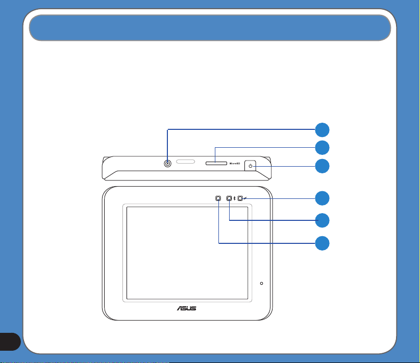
1.1 Layout features
ASUS R300 is a professional portable navigation device (PND) which provides reliable
navigation and positioning function. R300 also provide you with phone and multi-media
functions.
Front and top features
1
2
3
4
5
6
12
Page 13
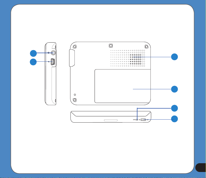
Rear and side features
7
8
9
10
11
12
13
Page 14
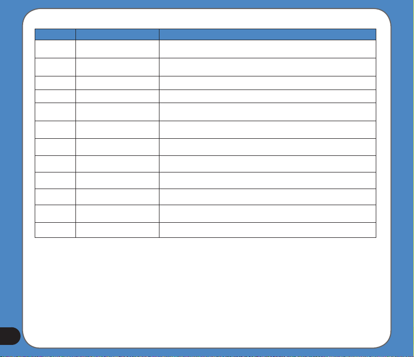
Number Item Description
Connects to an external antenna for better signal performance (the external
antenna is optional)
Insert the external Micro SD memory card to this slot
Press to turn on the device, or to enter into sleep mode
Red- charging, Yellow- full charged
When function turning on, it's lighting Blue
Automatically adjusts the backlight according to the light in the environment
Use to connect headsets or two-channel speakers
Connects to other devices through a Mini USB cable
Allows you to listen to music, the navigation voice, and system warning
Battery cover
Push to perform reset function
Turns the main power on/off
10
11
12
1
2
3
4
5
6
7
8
9
ExternalAntennaport
MicroSDSlot
SleepModeButton
ChargingLED
BluetoothLED
LightSensor
AudioJack
MiniUSB
Speaker
Battery
Reset
Mainpowerswitch
14
Page 15
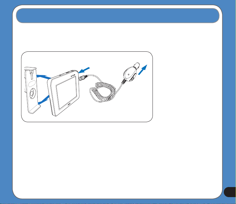
1.2 Charging the Battery
You can charge the device using a car charger kit. Plug any of these cables to the mini-USB
port on the right side of the device.
NOTE:
Car charger kit
When the Main Power
Switch is set to Off,
the device can not be
charged.
While charging, the
power LED lights up in
red. When the battery is
fully charged, the power
LED turns to yellow.
You can use the
device while charging.
However, the device
takes much less time
to be fully charged in
sleep mode.
15
Page 16
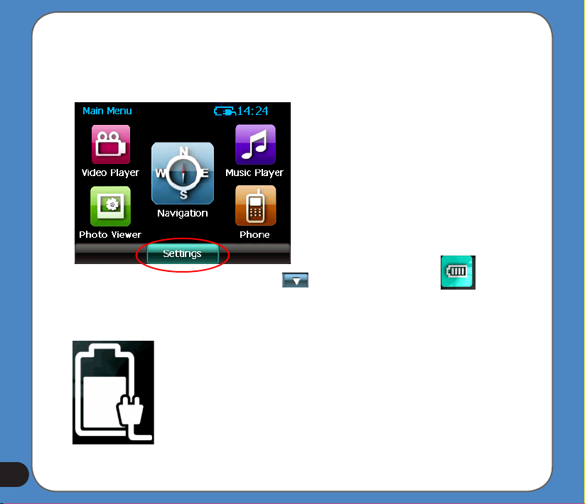
Checking battery status
To check how much battery power remains:
(1) From the main menu, tap Settings.
(2) The Sub-menu Settings appears. Tap to display Battery icon .
(3) The Battery screen appears and displays a battery icon indicating the battery power
that remains (see the gure below).
16
Page 17
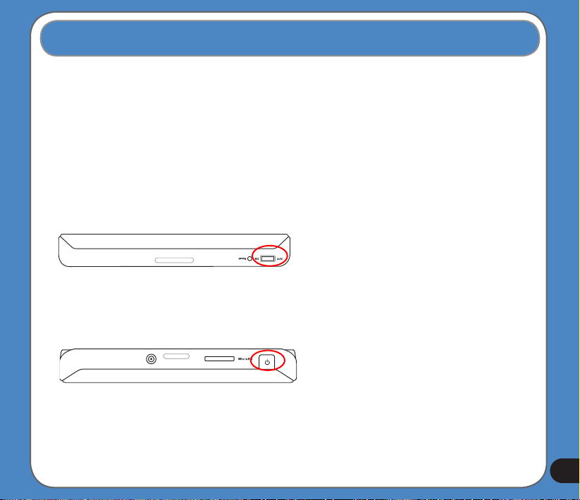
1.3 Turning on the Device
To turn on the device:
- Turn on the main power switch on the bottom of device (gure 1).
To enter/wake up from the sleep mode:
- Press the Sleep Mode Button on the top of the device (gure 2).
gure 1
gure 2
Main power switch
Sleep Mode Button
Note:
When the main power switch is set
to Off, the device is not able to be
charged.
If you press the Sleep Mode button
when the device is on, it enters into
sleep mode.
When the device is on, it takes
longer time for the battery to be
fully charged. When the device is in
sleep mode, the battery can be fully
charged quickly.
17
Page 18
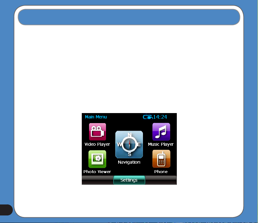
1.4 Main Menu
The following menu appears after you turn on the device. From the main menu, you can:
- Tap Navigation to enter the navigation system.
- Tap Settings to adjust the device settings.
- Tap Video Player to play videos.
- Tap Music Player to play music.
- Tap Photo Viewer to view photos.
- Tap Phone to use phone through the bluetooth connection.
Note: The FM transmitter icon only appears when the FM transmitter function is enabled.
18
Page 19
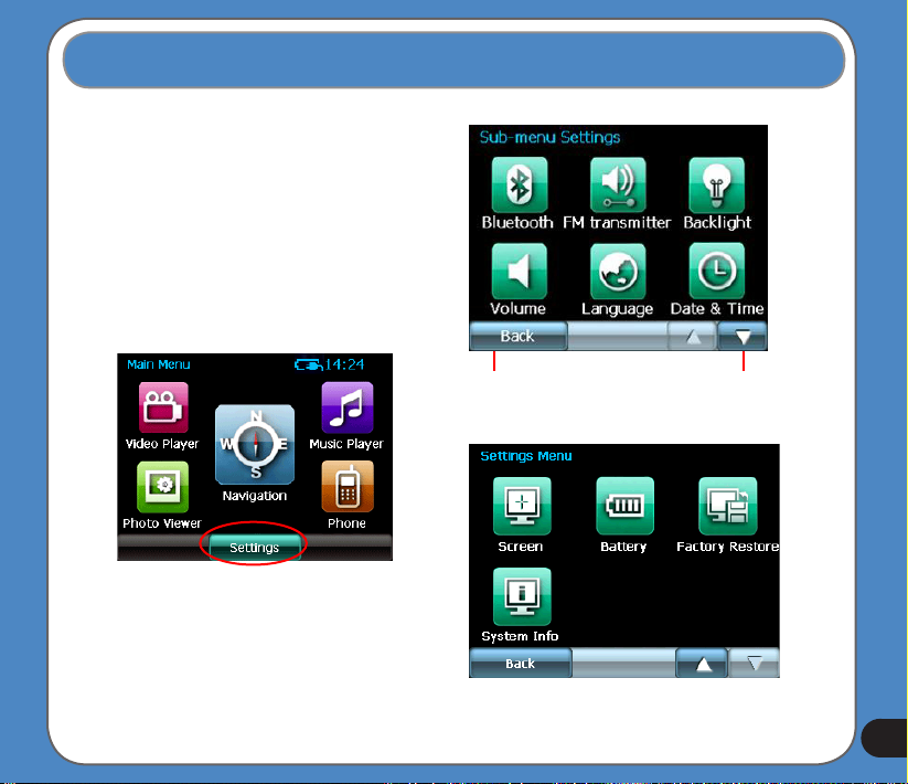
1.5 Adjust the basic settings
You can launch the basic settings menu
by tapping Settings on the main menu.
The settings menu allows you to adjust
language settings, backlight, Date and
time, bluetooth settings, volume, to align
screen, and to view system information.
tap to back
to the main
menu
tap to move
to the next
page
19
Page 20
System Infomation
System information screen display the ROM
version, Software Version and the screen
resolution and color information.
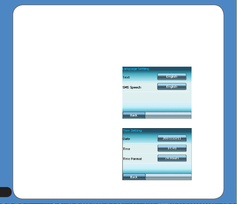
Language
You can choose the language for displaying
the text. Simply tap the bars behind the Text
to select the language.
Date and Time
To set the date and time, tap
from the settings menu. Tap the bars behind
Date, Time
them.
and
Time Format
Date and Time
to adjust
20
Page 21
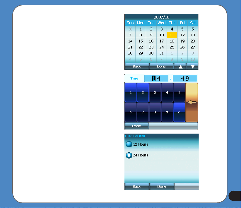
Set Date
Set time
Set time format
21
Page 22
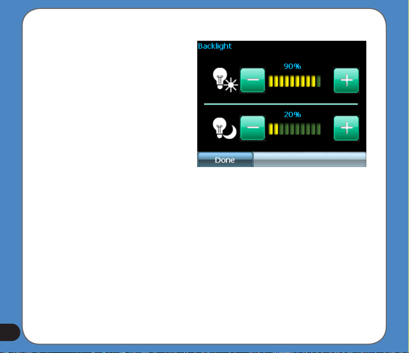
LCD brightness
Note: The device provides two LCD
brightness adjusting modes for you to
choose, one is Fix backlight brightness,
the other is Adjust by environment
brightness.
To adjust LCD brightness in Fix backlight
brightness mode, simply tap + or -.
To adjust LCD brightness in Adjustment by
environment brightness mode:
- tap the + or - behind the sun light icon
to adjust the LCD brightness in a lighter
environment
- tap the + or - behind the moon light icon
to adjust the LCD brightness in a darker
environment
22
Page 23
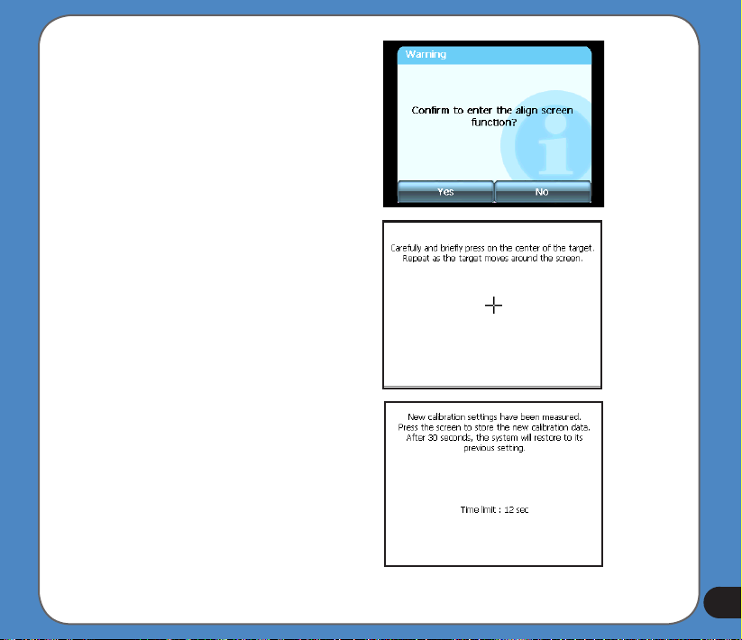
Screen calibration
Screen calibration ensures that the screen
accurately responds to the stylus.
To calibrate screen:
1. Carefully press and briey hold stylus on
the center of the target. Repeat as the target
moves to other coordinates on the screen.
2. When done, tap anywhere on the screen
for the settings to take effect; otherwise,
the new settings will be canceled after 30
seconds.
3. Tap on the screen to exit.
23
Page 24
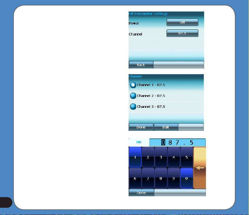
FM Transmitter
The FM transmitter allows you to transmit
navigation voice instruction and music/video
sounds to your car audio system through the
FM radio.
To use FM Transmitter function:
1. Tap FM Transmitter from the settings
menu.
2. Tap to turn on the Power and then to set
the Channel. Set the same channel as the
one on your car stereo.
The sound of R300 then can be broadcasted
and plays through your car stereo.
24
Page 25
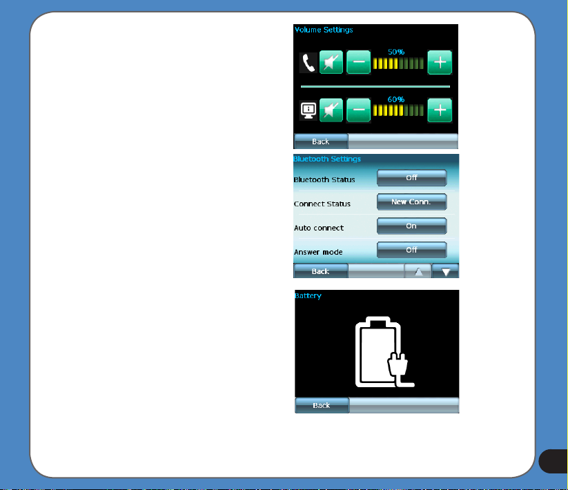
Volume
Tap
or
to adjust the volume for the
+
-
device and for the phone, or mute the device
and the phone.
Bluetooth
Enable bluetooth function to connect to a cell
phone.
Battery
Allows you to view battery status.
25
Page 26
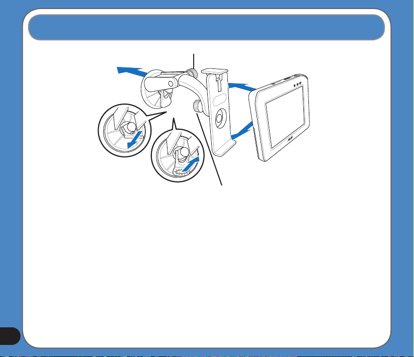
1.6 Installing the car kit
26
3
screwcap A
5
screwcap B
1
2
To install the car kit:
1. Attached the cupula to the windshield inside your car.
2. Press the lever to secure the cupula on the windshield surface.
Note: Rise the lever (3) to release the cupula from the windshield.
3. Adjust the angle of the gooseneck and secure it by fastening screwcap A.
4. Adjust the angle of the cradle and secure it by fastening screwcap B.
5. Carefully place and slide the device into the cradle.
Page 27
Chapter
Navigation System
Note: the screens and procedures in this chapter may not be exactly the same with those of
your device, please take them as reference only.
2
27
Page 28

2.1 Warnings and safety information
ASUS GO is a navigation system that helps you nd your way to your selected destination.
It will determine your exact location with the help of the built-in GPS device. The position
information obtained from the GPS receiver will not be transmitted anywhere, so others will
not be able to track you by the help of this program.
If you are the driver of the vehicle, we recommend that you operate ASUS GO before
beginning your journey. The driver’s attention should always be on the road. Plan your route
before departure and pull over if you need to change route parameters. ASUS GO has a
built-in (optional) Safety Mode that will prevent you from using the screen functions if your
car is in motion. Unless a passenger will be the only one to operate ASUS GO, we strongly
encourage you to turn on the Safety Mode.
It is also important that you look at the display only if it is absolutely safe to do so.
You should always observe trafc signs and road geometry before you obey any instruction
from ASUS GO. If you need to deviate from the recommended direction, ASUS GO will
suggest a modied route according to the new situation.
Never place the PNA where it can obstruct the view of the driver, is within the deployment
zone of airbags, or where it can cause injuries in case of an accident.
For further information, please consult the End User License Agreement.
28
Page 29
2.2 General information
ASUS GO is a navigation system optimised for in-car use. It provides door-to-door navigation
for both single and multi-point routes using adaptable route parameters. ASUS GO is capable
of planning routes throughout the whole installed map set. Unlike some other products,
ASUS GO does not require that you change maps or switch to a poorly detailed general map
to navigate between map segments or countries. You always have complete freedom to go
wherever you wish. Just select your destination and go.
You do not need a stylus to use ASUS GO. All screen buttons and controls are designed so
that you can operate them with your ngertips.
You can access all functions of the program by using hardware and screen buttons. With
the help of these buttons you can travel through all the screens of the program. Most of
the screens (especially menu functions and settings) can be accessed from several other
screens, minimising the number of actions needed to reach the desired function.
When using ASUS GO, you do not need to ‘double tap’ or ‘tap & hold’ the touch screen as
these functions cannot be used reliably in a moving vehicle. A single tap triggers most of the
screen controls. The only exceptions are ‘drag & drop’ for moving the map, or scaling it in Map
mode (Page 33).
Most of the screens have a Return button in the top left corner. This arrow returns to
the previous screen or directly to one of the map screens.
Settings screens also have a Help button in the top right corner. This will show a
detailed description of the current settings screen.
29
Page 30
30
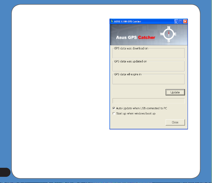
Instant Fix feature
Instant Fix allows you to update R300’s
GPS data and provide more accurate
satellite navigation services. Install this
application from the Bonus CD following the
procedures below:
1. Insert the R300 Bonus CD into the optical
drive. Open Instant Fix setup le to install it
in your PC.
2. Use the Mini USB cable to connect R300
to your PC.
3. Launch Instant Fix and click Update,
the system will connect to ASUS server
automatically and update the GPS data that
is stored in your R300.
4. If you want your R300 to automatically
update the GPS data when it is connected
to a PC (that has a internet connection),
check the Auto-Update when USB
connected to PC option, otherwise check
Start up when windows boot up.
Note: While using this feature, make sure
your R300 has a microSD card installed and
it is connected to a PC via Mini USB cable.
Page 31

2.3 Operating ASUS GO (Controls)
ASUS GO is designed for easy operation. All controls are operable by ngertips. Wherever
possible, pushbuttons and lists are provided to make accessing functions or changing settings
as easy as possible.
2.3.1 Hardware buttons
There are only a few hardware buttons on your ASUS R300.
The majority of the ASUS GO functions can be accessed using the touch screen. The
hardware buttons are the following:
Power on/off
Use this button to turn the power of the ASUS R300 on or off any time.
If the device power is turned off while ASUS GO is running, when you turn the device back
on, ASUS GO will continue the navigation as soon as the built-in GPS determines the location
again.
While the device is switched off, the GPS will not work, no position will be calculated, track log
will not be saved, and navigation will stop.
2.3.2 Screen buttons and controls
The primary input channel of ASUS GO is the touch screen. If you read on, you will realise that
most parts of the screen are not only used to display information but also to initiate functions
by tapping. Below you will nd a list of the most frequently used controls in the program.
31
Page 32

List selectors
When the values in the list need to be named, only the current value is shown (sometimes
together with a short description) in a horizontal stripe with arrows at both ends.
The arrows are buttons. Tap to move left in the list or move right. You need not conrm your
selection. As soon as you leave the screen, the selected value becomes effective.
Sliders
When a feature has several different unnamed (numeric) values, ASUS GO will show sliders
that look like analogue potentiometers to set the desired value.
If the value limits are not displayed at the ends of the slider, the leftmost position means the
minimum value, while the rightmost position represents the maximum value.
With most sliders you can check the current value on the left.
This control can be operated in two ways. Either drag the handle to move the slider to its
new position, or tap the slider where you want the handle to appear (the thumb jumps there
immediately). As with the list selectors, there is no need to conrm your selection. As soon as
you leave the screen, the selected value becomes effective.
32
Page 33

Switches
When a function can only have two values (mainly Enabled and Disabled), a switch is used.
Unlike with list selectors, the horizontal line contains the name of the function and not the
actual status. There is a lamp on the left to show whether the function is active or not.
When the lamp is dark , the function is not selected. When it is lit , the function is
enabled. The whole strip works as a button. Tap anywhere to toggle between the enabled and
disabled status.
Switches in the Quick menu
The switches of the Quick menu behave as normal switches but they look different in order to
t in with the other menu buttons.
Tap the button to toggle between the enabled and disabled states.
33
Page 34

Virtual keyboards
ASUS GO is designed in a way that you only need to enter letters or numbers when it is
inevitable. In these cases a full screen keyboard pops up that can easily be operated with
your ngertips. You can choose between a separate ABC and numeric keypad, or a set of
QWERTY-type keyboards that contain both letters and numbers. ASUS GO will remember
your last choice and offer it the next time you need to enter data.
The alphabetic keyboards in ASUS GO do not contain special characters, because you do not
need to enter accents when searching for a destination. Type only the base letters (the letter
most similar to the accented one) and ASUS GO will search for all their combinations in the
database (e.g. for the French street ‘Cité Bergère ’ you only need to type ‘Cite Bergere’, and
the rest is done by the program).
When you type in POI or track log names, ASUS GO will automatically turn all initials into
capitals to create names that look pleasant.
ABC-type keyboards
These keyboards contain only letters (Latin, Hebraic, Greek or Cyrillic). If you wish to enter
numbers, you need to tap the Keys button to switch to the numeric keyboard.
Use Backspace (arrow pointing left) to delete the last letter you have entered if you have
made a mistake, tap Space to enter more words, and hit Done to nish entering the text.
34
Page 35

This type of keyboard has large, nger-friendly buttons.
Note: If you have chosen a program language that uses Latin letters, only the ABC keyboard
appears. If you choose the Greek language, an additional keyboard appears with Greek
letters. Similarly Hebraic and Cyrillic letters are available when Hebrew or Russian is chosen
in Setup / Languages.
If you are used to computer keyboards, you may consider trying one of the QWERTY-type
keypads.
35
Page 36

QWERTY-type keyboards
QWERTY-type keyboards have both letters and numbers on them. Their layout is the same
as of the standard QWERTY, QWERTZ (German) and AZERTY (French) keyboards. To
switch to your desired QWERTY-type keyboard, press the Keys button repeatedly until the
appropriate keyboard appears.
The special keys described in the previous section are also available here.
The numeric keyboard
The numeric keyboard only contains numbers, on huge buttons. The special keys you nd
on the other keyboards (except Space) are available here as well.
36
Page 37

Although QWERTY-type keyboards also contain number keys, when entering a house
number, the program offers the more convenient numeric keypad.
2.3.3 Installing, updating or removing maps
You can upload new maps or update the maps with ASUS Navigation PCTool.
Requirements
• ASUS Navigation PCTool copied onto a PC running Windows XP
• Card reader in your PC that supports an SD card reader
Note: ASUS GO will only use the maps that are included in your ASUS GO licence.
To install or update maps
1. Download or copy the map(s) that you want to update or install into a folder on the PC.
2. Remove the SD card from ASUS R300 and put it into the card reader of the PC.
3. Start maploader.exe from the folder into which you have copied ASUS Navigation PCTool.
ASUS Navigation PCTool is launched: the maps on the PC are listed in the left-hand side of
the window, the maps on the SD card are listed on the right-hand side of the window.
4. Check which maps on the PC are marked with a green upward arrow .These are the
maps that are not available on the SD card or for which a newer version is available on the
PC.
5. Select the map(s) that you want to install or update (you can use Ctrl+Click and
SHIFT+Click to select several maps).
37
Page 38

6. Click Install below the PC map list. The selected maps are copied onto the SD card. The
up-to-date maps on the SD card are marked with a icon that has two parallel blue bars .
7. Remove the card from the reader on the PC and put it into the card reader of ASUS R300.
8. Start ASUS GO. The updated and new maps will be available for navigation.
To delete maps from the SD card
1. In the SD card list, select the map(s) that you want to remove (you can use Ctrl+Click and
SHIFT+Click to select several maps).
2. Click Remove below the SD card map list. The selected maps are copied from the SD
card to the following folder on the PC:
C:\Documents and Settings\<username>\Application Data \ASUS\maps\
You can back up the maps on the PC or copy them back to the SD card later.
3. Remove the card from the reader on the PC and put it into the card reader of ASUS R300.
4. Start ASUS GO. The deleted maps will not be available for navigation but you can copy
them back to the SD card at any time.
38
Page 39

2.4 Discovering the program through the screens
The best way to discover ASUS GO is to explore each screen in detail, and to nd out how to
move from one to another. Read this chapter for a guided tour.
2.4.1 Main menu
ASUS GO starts by displaying the Main menu. This is the root of the screen hierarchy, but
you need to return here very rarely while using the program. Screens are also accessible from
each other to reduce the number of actions needed to initiate a function or change a setting.
Most parts of the program are directly accessible from here by using the buttons described
below.
1 ASUS GO logo
2 Battery Status indicator
3 Button to open Cockpit screen
39
Page 40

4 Button to open Find menu
5 Button to open Settings
6 Button that displays GPS Status and opens the GPS Data screen
7 Button to minimise ASUS GO (navigation will not stop*)
8 Current position
9 Current date and time
10 Button to open Map screen
11 Button to open About screen
12 Button to exit ASUS GO** (navigation stops)
* Depends on program settings
** Same as removing the SD card
2.4.2 About screen
Tap About on the Main menu screen to open this screen. The About screen is not used in
normal navigation. It is there to inform you about the map licenses you have, the creators of
ASUS GO and the legal aspects of using the program.
40
Page 41

2.4.3 The map
The most important and most frequently used screens of ASUS GO are the two screens with
the map (Map screen and Cockpit screen). They are similar in look and in possible controls
but are optimised for different uses. The map they display is common. The elements of the
map are described here. For the controls and special functions of the two map screens see
Page 29.
The current version of ASUS GO is primarily intended for land navigation. That is why maps
in ASUS GO look similar to paper roadmaps (when using daytime colours and 2D map
mode). However, ASUS GO provides much more than regular paper maps can. The look
and the contents can be changed.
2D and 3D map views
Besides the classical top down view of the map (called 2D mode), you have the possibility
to tilt the map to have a perspective view (3D mode) that gives a view similar to that seen
through the windscreen with the possibility to see far ahead.
41
Page 42

42
It is easy to change between 2D and 3D modes. You have two options. You can use the Tilt
up and down buttons to tilt the map seamlessly between 2D and all 3D angles, or you can
use the switch in the Quick menu to quickly switch between the two modes.
Note: You may nd that 2D mode is more useful in North-up Map mode when looking
for a certain part of the map or an object to select as destination. On the other hand, 3D
mode in Track-up Cockpit mode with Smart Zoom makes navigation very comfortable. The
description of these modes will come later in this manual.
Note: 3D view is only useful for navigation. As you zoom out, the view angle will
automatically be raised. Finally 2D view will be reached. When you zoom back in, 3D view
will gradually return.
Page 43

Note: Using the Advanced settings, you can force Cockpit mode to always start in 3D Trackup view. You can still rotate and tilt the maps in either mode, but the next time you enter this
screen, the preset look will reappear. Similarly you can force Map mode to always start in 2D
North-up view.
Zoom levels
ASUS GO uses high quality vector maps that let you see the map at various zoom levels,
always with optimised content (the density of the map details can be independently set for
Map and Cockpit screens in Map settings. Street names and other text objects are always
displayed with the same font size, never upside down, and you only see as many streets and
objects as needed to nd your way around the map. Zoom in and out to see how the map
changes in either the 2D or 3D view.
Changing the scale of the map is very easy. You can drag and stretch the scale at the bottom
of the Map screen, or use the zoom icons on both Map and Cockpit screens.
Note: If you need to zoom out briey to locate your position on the map, use the Overview
mode instead of zooming out and back in. The Overview mode is a 2D North-up view that can
be started by tapping the compass button on the right.
43
Page 44

44
Note: ASUS GO has a special Smart Zoom function for navigation that automatically rotates,
scales and tilts the map in 3D map mode to always give you the optimal view in your current
situation. When approaching a turn, it will zoom in and raise the view angle to let you easily
recognise your manoeuvre at the next junction. If the next turn is at a distance, it will zoom
out and lower the view angle to at in order to let you see the road in front of you.
Daylight and night colour schemes
The different colour schemes let you adjust ASUS GO to the brightness of the environment.
Use the daylight and night colour schemes accordingly. Daylight colours are similar to
paper roadmaps, while the night colour schemes use dark tints for large objects to keep
the average brightness of the screen low, with carefully selected colours to still keep you
informed about all the necessary information on the screen.
You can change between day and night views manually in the Quick Menu or let ASUS GO
do it automatically for you.
Note: The automatic day/night mode is based upon the current date and GPS position by
which ASUS GO calculates the exact sunrise and sunset times on the particular day at the
particular location. Using that information ASUS GO can automatically switch between the
colour schemes a few minutes before sunrise, when the sky has already turned bright, and a
few minutes after sunset before it gets dark.
Page 45

Tip: There are several daytime and night colour schemes included with ASUS GO. To select
the one that suits your needs the best, make your selection in Settings.
Tip: To further enhance the effect of the night colour scheme, you can instruct ASUS GO to
decrease the display backlight when the night colours are used. Set the desired backlight
levels for both daylight and night modes.
Note: The colours mentioned and screenshots included in this manual refer to the default
daytime and night colour schemes. They may not look the same in the schemes you have
chosen.
Tip: If you use ASUS GO after sunrise or before sunset, look for the sun in the sky in the
map background using a at 3D view. It is displayed at its actual position to give you another
way to orientate, and also to provide some eye candy.
Streets and roads
The similarity of ASUS GO to paper roadmaps is also convenient when it comes to streets,
the most important elements of the map concerning navigation. ASUS GO uses similar
colour codes to those you are accustomed to, and the width of the streets also refers to their
importance, so it will not be difcult to tell a highway from a small street.
Streets and roads have names or numbers for identication. Of course, this information
can be displayed on the map. ASUS GO uses two different ways to show street labels. The
conventional way is the same as a roadmap – it displays the name of the street aligned with
the street. The alternative is a kind of virtual signpost stuck into the street itself.
45
Page 46

46
You need not choose between the two modes. ASUS GO will use the one best for the
current tilt and zoom level. Zoom in to have only a few streets on the map, and start tilting up
and down to see how ASUS GO switches between the two modes in an instant.
Note: The automatic switching is on even when using Smart Zoom. At rst you may nd it
odd, but later you will discover how it adjusts the displayed information to the current view of
the map. It is important, as the driver must be able to read the map at a glance.
Tip: If you do not want to be bothered by street names during navigation, turn them off in
Map Options.
Tip: Major roads usually have alternative names (numbering) besides the primary name.
You can choose whether to display these alternative names or not. You can set this in Map
Options.
Other objects
To help orientate you, the map also contains objects that have no other navigating function
than to help you recognise your location on the map. These are surface-waters, large
buildings, forests, etc.
Page 47

Tip: These objects are normally displayed using textured polygons that look natural to the eye.
You may wish to switch the textured display off to free some of the resources of your PNA by
replacing textures with plain coloured surfaces.
Current position and Lock-on-Road
When your GPS position is available, an arrow shows your location on the map.
The direction of the arrow represents your heading. The arrow is sized and vertically rotated
with the zoom and tilt levels to always look realistic.
ASUS GO has a built-in Lock-on-Road feature that always puts the position arrow on the
road, on the axis of the street in case of one-way streets, or on the side of the road where you
drive (e.g. on the right in Germany and on the left in the U.K.) on two-way roads.
47
Page 48

The location received from the GPS receiver is shown as a blue dot on the map. This can
help you locate your position if the GPS accuracy is poor, and the Lock-on-Road system
puts you on the wrong street. It is also the location saved in the track log.
Note: The Lock-on-Road feature can be turned off in Advanced settings (Page 78) for
pedestrian use. When switched off, the arrow is displayed at the position reported by the
GPS receiver.
When the GPS position is lost, the arrow turns grey, but the journey continues on the
recommended route for a short period of time with the speed last detected before the GPS
position was lost. When the next route event is reached, or after 40 seconds, the arrow
stops, and remains grey until GPS reception returns. This way short tunnels can be crossed
without losing the position.
Selected map point, also known as the Cursor
If you tap the map somewhere or select a specic item in Find, it will become the selected
point on the map, marked with a small red dot and permanently radiating red circles to make
it conspicuous at all zoom levels, even when it is in the background of a 3D map view. You
can use this point as starting point, via point, or destination of your route, you can search for
a POI near to it, mark it with a drawing-pin, or save it as a POI. The cursor, when visible, is
also the reference point for map scaling.
48
Page 49

Note: When your GPS position is available, and Lock-to-Position is active, the cursor is
the current GPS position, the arrow. When you select another point by tapping the map,
or using the Find menu, the new Cursor is shown on the display with the red dot and the
radiating red circles.
Marked map points (Pin)
The Cursor can be marked with a Pin. Pins are shown as being stuck in the map. A Pin is
visible at all zoom levels and remains in its position until you unpin it, or delete all Pins in
Advanced settings.
The colour of the Pin is automatically selected by ASUS GO. Different colours help you
identify a Pin in the History list later. There they are shown together with their address and
GPS Coordinates.
Tip: There is a quick way to save the current GPS position as a Pin. Press the Record button
(hardware button with an audio cassette icon on it) to save the Pin instantly.
Tip: A quick way to tell the coordinates of a location you found on the map is to Pin it, and
then look for the coordinates in the History list.This way you also save the coordinates with
the Pin for later reference. If you do not need the coordinates later, just select the point and
start Find Coordinates.
Visible POIs (Points of Interest)
ASUS GO comes with thousands of built-in POIs, and you can create your own POI
database as well. Having all of them displayed on the map would make the map too
crowded. To avoid this, ASUS GO lets you select which POIs to show and which ones to
hide using their categories and subcategories.
49
Page 50

POIs are represented by icons on the map. For a built-in POI it is the icon of the subcategory
of the actual POI. For points you create, it is the icon you had chosen when you created the
POI (it can be changed later).
These icons are large enough to recognise the symbol, and semi-transparent so as not to
cover the streets and junctions behind them.
When the map is zoomed out, the icons are not shown. As you zoom in, small dots appear at
the locations of visible POIs. Zooming in further makes the full icons appear.
50
Page 51

If two points are too close to each other so that icons overlap, a multi-POI icon is shown
instead of individual ones. Zoom in more to see them separately. (Should the two POIs
have the same icon, this icon will be displayed instead of the multi-POI icon.)
Note: When navigating, POI icons can be disabled together with street names. If you still
need this information during your journey, just drag the map to disable Lock-to-Position.
This will restore street names and POI icons immediately. Now tap Follow to reactivate
Lock-to-Position.
Tip: Tap the map on or near a POI item to see the list of the names of the nearest POIs in
a popup list, if it is enabled. To see the details of a particular POI in the list, tap the blue
’i’ icon on the right. If you have too may POIs nearby, this list may not be complete. In the
Cursor menu there is a button called POI that leads you to the screen of all nearby POI
items. There you can open them one by one to see their details, and select any of them as
a route point.
51
Page 52

52
Road safety cameras
Road safety cameras, such as speed cameras and red light cameras are special POI types
in ASUS GO.
Elements of the Active Route
ASUS GO uses a multi-destination routing system in which you have a start point (your
current location if GPS position is available), a destination, the line of the active leg of the
route, and optionally via points and inactive legs. They are all shown on the map.
The start point, via points and the destination
These points are represented by ags.
Page 53

Animated turn guidance
Animated arrows represent all route events other than the above-mentioned special points.
These arrows show the direction in which you need to continue your journey.
The active leg of the route
The active leg is the section of the route you are currently driving. If you have not added any
Via points, the whole route will be the active leg. When Via points are present, the active leg
is the part leading from your location to the next via point.
The active section is always the most conspicuous part of the map even when in the
background of a 3D map view.
53
Page 54

The line of the route is displayed on the driving side of the road for two-way and on the axis
in case of one-way streets. When the map is zoomed in and the line is wide enough, small
arrows show the direction of the route. This can be useful if you preview the route before
starting the journey or when entering a complex junction.
Inactive legs of the route
Future sections of a route are inactive. They are also shown on the map with the same
colour but a darker tint than the active one. An inactive route section becomes active as
soon as you reach its starting Via point.
54
Page 55

Roads in the route excluded by your preferences
Although you can choose whether to include or avoid some road types in Route parameter
settings, sometimes they are impossible to avoid near the starting point, via points or the
destination.
If so, ASUS GO will display those segments of the route with an alternate colour.
2.4.4 GPS Data screen
Tap the small satellite dish icon on the Main menu, Map or Cockpit screen to open this
window.
The GPS Data screen is a collection of information received from the GPS device and it also
serves as the entry point to the following screens:
• TMC,
• Time Sync.
55
Page 56

You can nd a GPS button on this screen, too, which serves as a switch for turning GPS
on/off.
Tip: You can plan routes from places other than your current position by switching the GPS
off, otherwise the starting point is always the place where the GPS signal is received. Also,
you can save battery life by turning off GPS reception.
GPS data displayed
The virtual sky on the left represents the currently visible part of the sky above you, with your
position as the centre. The satellites are shown at their current positions. The GPS receives
data from both the green and grey satellites. Signals from the grey satellites are only received,
while green ones are used by the GPS to calculate your current location. On the right you
can see the satellite signal strength bars. Grey bars are for the grey and black bars are for
the green satellites. To identify satellites use their numbers also shown in the virtual sky. The
more satellites your GPS tracks (the green ones), the better your calculated position will be.
Additional pieces of information on this screen are: current position in latitude/longitude
format, elevation, speed, date, time and calculated accuracy.
Note: Accuracy can be affected by several factors the GPS cannot take into account. Use this
accuracy information only as estimation.
There are two icons on the left to show the status of the GPS connection and the quality of
reception.
Tapping the GPS button stops and starts the GPS engine.
56
Page 57

GPS connection indicator
In the middle to the left there is a lamp similar to the ones used for switches. This one has
more colours and represents more values:
• a fast blinking green lamp means that there is communication with the GPS and data
is being received,
• other colours may not appear with a built-in GPS. Should any of these
appear, this means a faulty operation of your device.
GPS data quality indicator
In the top left corner there is a satellite dish to show the quality of the GPS position. Different
colours represent different signal quality:
• black with a red cross means there is no connection with the GPS device. This
should never be the case if your device has a built-in GPS.
• red means the GPS is connected but no GPS position is available,
• yellow means 2D reception. A GPS position has been acquired, ASUS GO is ready
for navigation, but the GPS is using enough satellites for calculating the horizontal position
only. Elevation data is not provided, and the position error may be signicant.
• green means 3D reception. The GPS receiver has enough satellites to calculate
altitude. Position is generally correct (yet it can still be inaccurate due to different
environmental factors). ASUS GO is ready for navigation.
57
Page 58

Time synchronization
In the top right corner of the screen you have another button that leads to a new screen
where you can synchronize the clock of your PNA to the very accurate time provided by the
connected GPS.
Turn on the Auto Correction switch to let ASUS GO frequently check and correct the internal
clock of the device with the GPS time.
Below that button you will see the current values of the GPS and the device clocks. You can
check here whether any correction is needed. Tap the downward arrow button to manually
synchronize the time.
Below the PNA time you have hour and minute controls to manually correct the time
with or without a valid GPS time. It also gives you the chance to correct the time after
synchronization if your PNA does not support time zones or daylight saving time.
58
Page 59

2.4.5 Screens with map
Having explained the contents of the map, the description of the other parts of the map
screens follows. There are two map screens: the Map screen and the Cockpit screen. The
way they show the map is the same but their look and controls are optimised for different
purposes.
The Map screen is to be used mainly without a GPS, to browse the map, create user POI
items, or to plan your route based on map points. The Map screen is designed to give you
the maximum map area. This screen is usually used in 2D North-up mode.
You can set ASUS GO so it always opens the Map screen in 2D North-up mode (Page
73).
The Cockpit screen is for driving purposes. Besides showing the map, it contains some
additional travel information if you are just cruising (speed, current street you are driving
in, speed limit for the current street), and some more route data if you are navigating (e.g.
next street in your route, distance to travel, type of the next route event). This screen is
typically used in 3D Track-up mode.
You can make ASUS GO always open the Cockpit screen in 3D Track-up mode.
There are several controls that function in a similar fashion on the two screens. They are
described on the following pages.
59
Page 60

Map screen contents:
Cockpit screen contents:
1 (Cockpit only) Turn preview. Opens Route menu*
2 Zooms in (optional)
60
Page 61

3 Zooms out (optional)
4 Tilts down (optional)
5 Tilts up (optional)
6 Indicates that Lock to GPS position and heading is inactive. Re-enables Lock-to-Position /
Smart Zoom
7 Selected map point (Cursor). Opens Popup Info and Cursor menu
8 (Map only) Map scale. Zooms in/out by dragging
9 Menu (Find, Quick, Route, Main)
10 Map orientation and Overview. Switches North-up, Track-up and Overview
11 GPS position quality. Opens GPS Data screen
12 Battery status. Opens settings
13 Sound on or muted. Enables/disables muting
14 Track Log recording or playback. Opens Track Logs screen
15 Opens Cursor menu
16 (Cockpit only) Current street. Opens Route Information screen
17 (Cockpit only) Travel and Route data**. Opens Route Information screen
18 (Cockpit only) Distance to next turn***
61
Page 62

62
19 (Cockpit only) Next street***
20 (Cockpit only) Approaching next turn****
* On Map screen only when a route is active
** Contents differ when a route is active
*** Appears only when a route is active
**** Appears only when a route is active and the next turn is near
Turn preview (No. 1)
On the Cockpit screen this eld shows a graphic illustration of the next manoeuvre. For
example when you approach a turn, an arrow will show whether it is a slight, normal or sharp
turn. When showing a roundabout, the number of the exit is also given in the picture.
This eld also serves as a button. Tap it to get to the Route menu. The Map screen will show
a button called Route here if there is an active route. This also leads to the Route menu.
Zoom in and out (No. 2 & 3)
These semi-transparent buttons are only displayed if “Zoom & Tilt” is enabled in the
Quick menu.
Page 63

Zoom will change the scale of the map. Zoom out shows a larger part of the map, while
Zoom in shows a smaller part of the map in more detail.
The automatic Smart Zoom function will do the necessary zooming for you when navigating
(zooms out if the next turn is at a distance to let you see far ahead and zooms in when
approaching a turn to give you a better view of the upcoming manoeuvre). If you manually
change the zoom level, Smart Zoom will no longer scale the map by itself (automatic tilting
and rotating remains active).
You need to tap the Follow button to return the zoom control to Smart Zoom. You can also
set ASUS GO to do this automatically after a few seconds in case of the Cockpit screen.
Tilt up and down (No. 4 & 5)
These semi-transparent buttons are only displayed if “Zoom & Tilt” is enabled in the
Quick menu.
This function modies the vertical viewing angle of the map in 3D mode. You can change the
angle in a wide range starting from a top down view (2D view is seamlessly integrated) all
the way to a at view that lets you see far ahead.
The automatic Smart Zoom function will do the necessary tilting for you when navigating
(gives a at view if the next turn is at a distance to let you see far ahead and raises the
angle when approaching a turn to give you a better view of the upcoming manoeuvre). If you
manually change the view angle, Smart Zoom will no longer tilt the map by itself (automatic
zooming and rotating remains active).
You need to tap the Follow button to return the tilt control to Smart Zoom. You can also set
ASUS GO to do this automatically after a few seconds.
63
Page 64

Follow mode - lock to GPS position and heading (No. 6)
This semi-transparent icon is displayed if GPS position is available, and the map
has been moved. It also appears when you scale or tilt the map while Smart Zoom is
enabled.
This semi-transparent icon is displayed if GPS position is available, and the map has been
moved or rotated. It also appears when you scale or tilt the map while Smart Zoom is enabled.
Normally ASUS GO positions the map to keep the GPS position visible somewhere on the
map (when North-up orientation is selected), or always at the bottom centre of the map (when
Track-up orientation is selected).
If you manually move the map, it will freeze the map in the new position. To return to the GPS
position, use this Follow button.
When Smart Zoom is enabled, scaling or tilting the map also stops the automatic zooming or
automatic tilting respectively. To reactivate Smart Zoom, tap this button.
Tip: In Advanced settings you can set a delay time after which ASUS GO pushes the Follow
button for you on the Cockpit screen automatically. This can be turned on for re-enabling both
Lock-to-Position and Smart Zoom.
Cursor (No. 7)
As described earlier, if you tap the map somewhere or select one specic item in Find, it will
become the selected point on the map, marked with a small red dot and radiating red circles
to make it conspicuous. You can use this point as starting point, via point or destination for
your route, you can search for a POI near it, mark it with a pin, or save it as a POI.
64
Page 65

Note: When GPS position is available, the Follow button will appear indicating that you
have disabled Lock-to-Position. Tapping the Follow button will re-enable the position lock
and move the cursor back to the current GPS position. The same happens when ASUS
GO restores Lock-to-Position automatically on the Cockpit screen, if it is set in Advanced
settings.
Map scale (No. 8)
The scale indicator is only available on the Map screen. In 2D map view it represents the
scale of the map. In 3D view it is the scale of the nearest part of the map only.
You can use it in both 2D and 3D modes to scale the map. Drag and pull it right to zoom in,
or left to zoom out.
Menu (No. 9)
This button opens the Menu with the Find engine, the Quick menu, the Route menu and the
exit button that takes you to the Main menu screen. The Menu will be described in detail
later.
Map orientation and Overview (No. 10)
You can view the map screens in three different presentation modes. This switch will cycle
through them in the following order.
The usual map orientation for navigation is Track-up. It means ASUS GO rotates the
map during navigation to always face the direction of your travel. In this mode an arrow
(compass) points towards North.
65
Page 66

Tap this icon to switch to North-up mode. Now the map is xed to keep facing North. The
icon changes to show the new rotation mode.
Tap the icon again to enter Overview mode. This mode looks similar to the North-up mode
with one difference: the zoom level in this mode has a xed default to give you a better look
of where you are on the map. You can change the zoom level at any time, this will not cause
the Follow button to appear, but when entering Overview mode later, the default zoom level
will be restored.
The arrow representing your position will be xed in the middle of the screen. When you
move the map in Overview mode, the Follow button will appear, and when pushed, it will
move the map to have your current position in the middle of the map again.
You cannot rotate the map in Overview mode. This mode is strictly north-up.
You can set up ASUS GO so that it will switch to Overview mode during navigation when the
next turn is far away. You can specify this distance and the xed zoom level of Overview in
Advanced settings.
An aeroplane icon indicates Overview mode.
Tap the icon again to return to Track-up (automatic rotation) mode.
GPS position quality (No. 11)
Similarly to the icon found on the GPS Data screen, the map screens also inform you about
the GPS signal:
66
Page 67

• The black satellite dish with the red exclamation mark shows there is no connection
with the GPS receiver. GPS navigation is not possible. Devices with a built-in GPS receiver
are permanently connected, so this icon may not appear under normal circumstances.
• Red shows there is a connection, but the signal is too weak to give a position. GPS
navigation is not possible.
• Black shows there is a GPS position, and navigation is possible. When only one arc
is shown, the position is 2D (no altitude available), and position error may be signicant, yet
ASUS GO is ready to navigate.
• A black dish and two arcs represent a 3D GPS position. ASUS GO is ready to
navigate.
• When small car symbols are displayed under the dish, TMC information is available.
Battery status (No. 12)
The status of the battery is also shown by ASUS GO. You can estimate the available power
reserve from the length of the bar inside. Some examples:
• The thunderbolt in the battery shows the battery is being charged.
• Battery is not charging, but it is at full capacity.
• Battery in not full, but there is sufcient reserve capacity.
• When the inside of the battery turns red, the battery needs recharging.
67
Page 68

Sound muting (No. 13)
By tapping this button you can quickly mute all sounds of the PNA. This will not modify the
volume level and the enabled or disabled status of the voice guidance or the key sounds
(all to be set on the Sound Settings screen, just mutes the sound output. When muting is
enabled, the speaker icon is crossed out.
Tap again to re-enable sounds.
Note: Sound can be muted in Sound settings, too. There you have a Master switch that
works together with the switch described above. There is also a Master slider on that screen.
That you can use to fully turn down the volume of the device. Setting the volume low is
different from muting, therefore it will not show up on the mute indicator.
Track Log recording/playback indicator (No. 14)
When a track log is being recorded, a red icon is displayed on the map screens. This icon
also functions as a button leading to the Track Log screen (Page 48) where you can stop the
recording or make the track log visible on the map.
During track log playback a green icon will blink. Tapping this icon (in fact, tapping the
screen anywhere) stops the simulation.
68
Page 69

Cursor menu (No. 15)
The Cursor is the selected point on the map (marked by a red dot and radiating red circles
around it), or the current GPS position when it is available and Lock-to-Position is enabled.
When you tap the screen to place the Cursor, the Cursor menu pops up automatically to
give you the list of possible functions you can use the Cursor for. At the same time Popup
Info (street name, house number and the list of POIs nearby) appears near the selected
map point if Popup Info is enabled in the Quick menu.
If you do not use the Cursor menu in a few seconds, it will automatically vanish back to
the bottom of the screen, and Popup Info disappears, too. You can have them reappear by
reopening the Cursor menu using the arrow in the bottom right corner. When you open the
menu manually, it will stay on until you close it or switch to another screen.
Tip: If you want to see the map around the Cursor, close the Cursor menu and reopen it.
When this menu is opened manually, the map is always moved to have the cursor in the
centre.
The content of the Cursor menu depends on the screen (Map or Cockpit) and it is slightly
different if there is an active route already planned. You have the following options:
69
Page 70

70
• Start: use the Cursor as the departure point for your route. This menu point is available
only in Map mode and when there is no active route. In Cockpit mode the departure point of
the route is always the GPS position or if it is not available, the last known GPS position.
• Route To: use the Cursor as the destination of your route. This button is to start a new
route. The previous route (if it exists) will be deleted and replaced. If a multi-point route is
active, ASUS GO will ask you whether you really want to delete it together with all its via
points.
• Add Via: by inserting the selected map point as a via, you instruct ASUS GO to cross this
location before the destination of the route. This is the way to build a multi-point route in
reverse order (when you wish to insert a stopover ‘go to A but rst get some fuel at B’ or
want to inuence the direction of the route). This menu point works only if a route is already
active.
• Remove Via: removes the ‘via point’ near or at the Cursor. The route will be recalculated
immediately excluding the deleted point. This menu point replaces Add Via and is available
only if the Cursor is near or at a via point.
• Continue: add a new destination to be reached after the previous destination. The new
destination replaces the old one, which is now demoted to a via point. This is the way to
build your multi-point route in straight order (when you wish to visit several destinations ‘go
to A then to B’). This menu point is available only if a route is already active.
• Pin: push a coloured pin in the map at the selected point for later use. This pin is visible
at all zoom levels and also appears in the History list together with its exact position. The
colour of the pin is automatically selected by ASUS GO.
• Unpin: remove the pin near or at the Cursor. This menu point replaces Pin and is available
only if the selected point is near or at a pin.
Page 71

• POI: opens the list of POIs near the selected point. These are the POIs shown in the
Popup Info window. This menu point is only available on the Map screen. If you want to
add a new POI at the cursor, you can do so by tapping Add POI in the bottom left corner.
You can also add a new road safety camera if you tap Add Cam, and set the parameters
(type, direction, and speed). If a camera already exists near the cursor, this button is
inactive, and you can change the parameters of the camera by tapping it in the list.
Current street (No. 16)
This eld of the Cockpit screen shows the name or number (as available) of the current
street or road you are driving on.
Tip: Some roads have an alternative name (or number). This is normally shown together
with the primary name in this eld. You can hide these alternative names in Map settings.
Travel and Route data (No. 17)
The contents of these three elds are different when cruising (without an active route) or
navigating (following an active route).
While cruising, the elds show the present speed, the current speed limit and the time of
day.
While navigating a route, these elds show the estimated time needed to reach the
destination (ETE), the distance to destination, and the estimated arrival time at the
destination (ETA) by default.
71
Page 72

You can choose what to display in these three elds during navigation, by going to Advanced
settings / Display Options. See the following list for your options. The only restriction is that
you cannot select a value that already appears in another eld. The possible eld contents
are:
• Distance to destination (default value for the left eld)
• Time to destination (estimated time en route, default value for the middle eld)
• Distance to next via point
• Time to next via point
• Time to next manoeuvre (next route event)
• Speed
• Speed limit
• Arrival at next via point
• Arrival at destination (default value for the right eld)
Distance to next turn (No. 18)
This eld shows the distance to go before reaching the next route event (turn, roundabout,
exit, etc.)
This eld is only displayed when navigating a route.
72
Page 73

Next street / Next settlement (No. 19)
This eld shows the road or street that comes next in the route itinerary.
If you are not yet in the settlement where this next street is, ASUS GO will display the name
of the settlement instead of the name of the road or street. A bullet symbol will appear next
to the name of settlements to help you tell them apart from street names.
This eld is only displayed when navigating a route.
Approaching next turn (No. 20)
This bar is only visible when approaching the next route event. It appears on the screen to
visualise the distance when you get closer than 300 meters (1000 feet) to the next turn, and
it remains visible till you reach the turn.
This eld is displayed only when navigating a route.
73
Page 74

Bluetooth or Phone call status
When Bluetooth is turned off or the Bluetooth-capable device is not connected, the Bluetooth
icon is not displayed.
When Bluetooth is turned on and the Bluetooth-capable device is connected, the Bluetooth
icon is displayed:
If you tap the icon, ASUS GO pauses and the Bluetooth Dialer screen appears.
During a phone call using the ASUS R300 as a handsfree tool for your mobile phone ASUS
GO is paused, and you see the phone call screen. You can continue navigation without
stopping the phone call with the button in the top right corner. Then navigation continues
without voice guidance (sound is reserved for the phone call), and an icon depicting a
telephone handset is shown here.
Tap the icon to pause ASUS GO to go to the In Call Screen.
When you hang up the call, the icon returns to the blue Bluetooth logo.
74
Page 75

2.4.6 Route Information screen
The Route Information screen has all the data and some of the functions you need while
you navigate. Some additional functions can be found in the Route menu. Without an active
route one of the buttons is inactive and route data cannot be displayed.
As a reminder, you can open this screen two ways: tapping the Info button in the Route
menu, or tapping one of the Route Data elds on the Cockpit screen.
Route data displayed (for destination and via points)
In the top section of the screen you see information about the current route. These elds are
continuously updated while you keep this screen open.
When you open the screen, all elds contain information on reaching your nal destination.
Tap any of the elds to see data on the via points starting from the rst one through the nal
destination again.
75
Page 76

76
Route line
The upper part of this screen shows your planned route as a horizontal line. Its leftmost
point is the start of the route, the rightmost one is the nal destination, and you can see your
via point ags along the line, spaced in proportion to their distance.
The arrow representing your position will travel from the left to the right, giving you visual
feedback of your journey.
When you reach a via point, it becomes the starting point of the route, the past will be
deleted, the line with all the other via points will be modied instantly, and the arrow jumps
back to the left.
Page 77

When ASUS GO needs to recalculate the route, the arrow will not jump back to the left as
when reaching a via point, but it may drift a bit as the length of the new route may be different
from the previous one.
When the data corresponding to the entire route is displayed in the elds below, the line is
coloured the same way as the route line shown on the map. When you see data that belongs
to a via point, the route is coloured only up to that via point. The rest of the line remains grey.
Distance Left
This value can also be displayed in one of the Route data elds on the Cockpit screen as
‘Distance to destination’. This is the distance you need to travel on the route before reaching
your nal destination.
If via points exist, tap and tap again any of the elds to see the distance to reach the rst,
second, etc. via point.
Method
This eld shows how the route was calculated. It either displays the ‘Route’ or the ‘Vehicle’
eld from the Route parameter settings. If you have chosen Car, Taxi, Bus or Lorry, the type of
the route (Fast, Short or Economical) will be displayed here; if you have selected Emergency,
Bicycle or Pedestrian, this information will be displayed here.
Time Left
This is an estimated value that can also be displayed in one of the Route data elds on the
Cockpit screen as ‘Time to destination’. It shows the time needed to reach the nal destination
of the route based on information available for the remaining segments of the route. The
calculation cannot take into account trafc jams and other possible delays.
77
Page 78

If via points exist, tap and tap again any of the elds to see the time needed to reach the
rst, second, etc. via point.
Estimated Arrival
This is an estimated value that can also be displayed in one of the Route data elds on
the Cockpit screen as ‘ETA to destination’. It shows the estimated arrival time at the nal
destination of the route based on information available for the remaining segments of the
route. The calculation cannot take into account trafc jams and other possible delays.
If via points exist, tap and tap again any of the elds to see the estimated arrival at the rst,
second, etc. via point.
Destination / Via point
This eld shows the exact address (or its coordinates if the address is not available) of the
nal destination.
If via points exist, tap and tap again any of the elds to see the address or coordinates of the
rst, second, etc. via point.
Warning icons
The following 5 squares are normally grey. Some of them turn red and show a graphical
symbol in case warning(s) are attached to the planned route. These are warnings, so icons
always show information for the whole route, even if the data elds display values from your
current position to a via point only.
Click on any of the icons to show its description.
78
A few samples of the available icons:
Page 79

• This icon shows that you need to pay toll on the recommended route.
• This icon shows that the route contains motorways. Tap the icon to see the total
length of the motorways in the recommended route.
• This icon shows that toll motorways are included in the recommended route.
• This icon shows that you need to board a ferry along the recommended route.
• This icon shows that you need to pay for the ferry.
• This icon is displayed when ASUS GO could not plan a route with all your road type
preferences respected. Sometimes it is impossible to nd a suitable route near the start or
the destination.
• This icon warns you that ASUS GO had to recommend a route that does not match
all your preferences given at the Route Parameters settings.
• The recommended route contains areas only accessible to pedestrians.
• The recommended route contains unpaved roads.
• The recommended route contains roads that require a permit or permission to enter.
• Information – any other piece of relevant but not categorised information. Tap the
icon to see the content.
• Next page – displayed when more than 5 warnings apply for the recommended
route.
79
Page 80

Fit to screen
Tap this button to display an overview of the whole recommended route. You will jump to the
Map screen with a 2D North-up view so that you can check where the route takes you.
Parameters
This button opens the Route parameter settings screen (Page 68) otherwise opened from the
Route menu.
2.4.7 Menu
The Menu button can be found in the bottom left corner of the map screens.
Tapping this button brings up a menu that allows you to access some of the most frequently
used functions of ASUS GO.
Find tab
The rst page of the Menu is Find. It lets you select a destination without rst having to locate
it on the map.
80
Page 81

Quick tab
This provides quick access to some congurable options.
3D Map (switch)
When the light is on, the map shows a perspective view. You can use hardware buttons 1
and 2 to change the angle of the view. When the green light is off, the map is displayed in a
conventional top-down view. This 2D view is also the end of the tilt range, so it can also be
accessed by tilting the map up. Conversely, 3D mode can be switched on by tilting down in
2D mode.
81
Page 82

Note: When you reach 2D view by tilting the map, Smart Zoom will tilt the map as you press
the Follow button or it disappears after the timeout (set in Advanced settings) expires. Use
the 3D Map toggle to permanently switch to 2D view.
Note: If the map is zoomed out so that the view angle is automatically raised to a top down
view, this button will have no immediate effect. When you zoom back in, the view angle will
or will not change according to the new state of the button.
Zoom & Tilt (switch)
When the light is on, additional transparent buttons appear on the left side of the map
screens for zooming and tilting without the use of hardware buttons.
The Tilt buttons appear only at higher zoom levels. If you zoom out, they disappear.
82
Page 83

Night Mode (switch)
Turn on or off the night colours manually to override the automatic colour scheme switching.
Note: Using this option turns off the Automatic Night Colours feature. You need to re-enable
it at the General settings screen to have the colours change automatically again.
Manage POI (Points of Interest)
Here you can set all the parameters of POIs that you have created and the visibility of the
built-in POIs that come with the map.
Manage built-in POI visibility
The maps in ASUS GO come with a huge number of POIs. Displaying all of them would
make the maps too crowded (to see how POI items are shown on the map. In order to avoid
that, you can decide which POI groups to show and which ones to hide on the map. ASUS
GO has a multi-level POI category system. You can set the visibility of the top two levels. All
levels below that will be shown or hidden according to their respective category (i.e. you can
set the visibility of Petrol Stations in the Services category, but all brands listed under that
will either be shown or suppressed together).
83
Page 84

84
Groups shown with a tick mark are visible on the map; groups without a tick mark are
hidden, while the ones shown with a pale tick mark have some of their subcategories
shown and some others hidden.
If you highlight any of the POI groups, the button in the bottom left corner will become Show
if the POI group is hidden, or Hide if the group is shown or partly shown.
Tip: To make a partly shown group fully shown, tap this button twice. First you will hide the
whole group, and then you will have it displayed with all its subgroups.
Tapping again the highlighted POI group (except for My POI – described later) opens the list
of subcategories of that group. Here you cannot see partly shown subgroups, as visibility
can only be set for the top two levels of categories. Showing and hiding a subgroup is done
the same way as for the main groups.
Page 85

Manage My POI
By highlighting then tapping again the My POI switch on the Manage POI main screen you
can manage the POI groups and items that you have created.
Note: The group Unnamed only appears if you have previously saved a POI item without
creating a new POI group for it.
85
Page 86

Tapping any of the group names will open a list of POIs saved in that group. This list is
similar to the list of POI results in Find. The POIs are ordered based on their distance from
your current position. If GPS position is not available or you have disabled Lock-to-Position
by tapping the map, the POIs will be ordered by their distance from the Cursor.
When the My POI Groups are displayed, you have the following options:
• Show/Hide: similarly to built-in POIs, you have the possibility to show or hide all POIs of
the selected category on the map. Groups with a tick mark are displayed; all other groups
are hidden.
• New: you can create a new My POI group by tapping this button. You need to select an
icon, a name, and the maximum zoom level at which the POI is still visible on the map
(provided you let the POI group be displayed at all). You do not necessarily need to create
POI groups in advance. You can do it while saving a new POI.
• Delete: you can delete any of your previously saved My POI groups. This will delete all
POIs in that group. ASUS GO will ask you to conrm this action.
86
Page 87

• Edit: you can edit the attributes (name, icon, visibility level) of a previously created My
POI group.
• Left/right arrows: if your groups ll several pages, these buttons will let you browse
through them. The green eld left of these buttons shows the current page number and the
number of pages.
When the list of My POIs is displayed, you have the following options:
• Search: you can shorten the list of matching POI items by ltering. Just like in Find, enter
a few letters of the desired POI name. When the number of matching items can t in one
page, ASUS GO will automatically display the list. If you tap Done any time before this
happens, you receive the list of matches on multiple pages.
• ABC/Distance: by tapping this button you can have the POIs sorted in an alphabetical
order. Tapping again will return to the distance-based order.
87
Page 88

When you tap on any of your POIs in the list, you will open a new window with the details of
the selected POI.
Here you have the following options:
• OK: if you tap this button, the map screen returns with the selected POI in the middle.
• Edit: you can edit the attributes (name, icon and group) of the selected POI.
88
Page 89

• Delete: you can delete any of your previously saved POIs. ASUS GO will ask you to
conrm this action.
Popup Information (switch)
When this feature is enabled, tapping the screen (activating the Cursor, a radiating red dot)
on either of the map screens also opens a pop-up box with the selected street name, house
number and the name of the nearby POIs, if any.
Tip: Tapping one of the blue Information icons behind the POI names shows the details of
the appropriate POI item.
89
Page 90

Manage Track Logs
Using ASUS GO it is also possible to save the track logs of your journeys. This screen lets
you manage all your track logs. When it comes up, it shows a list of all track logs already
saved.
The original name of a track log is the date and time when it was recorded. You can change
their name to something more meaningful if you wish.
Each track log has a colour, shown to the left of its name when the track log is visible on
the map. If the track is not visible, a horizontal line is shown here. Tapping the line of the
highlighted track log will toggle between showing and hiding that log. The track log will be
drawn on the map using the colour next to its name.
90
Page 91

When a track log is being recorded, a new line appears in this list with a horizontal line, as
newly recorded track logs are not shown in the map normally.
Tip: If you wish to see the track log currently being recorded, highlight its line then tap again
to make it visible.
In this screen you have the following options:
• Record: this will initiate track log recording. A new line appears in the list, and GPS position
data will be saved until you stop the recording or exit ASUS GO. A red icon is shown on the
map screens to let you know that a recording is in progress. Tapping that icon opens this
Track Log screen.
• Stop recording: if recording is in progress, this buttons stops it.
• Info: this button opens a screen that shows the track log details, and lets you:
• change the name of the track log (Rename button),
• change the colour of the track log (Colour on the map selector),
91
Page 92

• have it displayed on the map (Fit to screen button),
• or export the data to the SD card in GPX format (Export button).
• Replay: push this button to see a simulation of the saved track log on the map. A green
icon will appear on the map screens to let you know it is a simulation only.
• Delete: you can delete a track log if it is not needed any more. ASUS GO will ask you to
conrm this action.
• Track log options: this button in the upper right corner leads to a settings screen where you
can set up the track logging parameters:
• Update interval is how often track points will be saved. Position information is normally
received once a second from the GPS. If you do not need such a detailed log, you can
increase this number to save track log space.
92
Page 93

• Current autosave track size: this gure shows how much memory is used by the
automatically saved track logs.
• Enable auto-saving: when auto-saving is enabled, you do not need to turn track log saving
on and off manually. ASUS GO will automatically start recording the track log as soon as
GPS position is available.
• Limit track DB size: here you can set whether or not to maximise the size of the database
where the automatically saved track logs are kept.
• Maximum track database size: here you can set the maximum database size if the track
database size limit is enabled using the previous switch.
• Create NMEA/SIRF log: independently of the normal track log, you can instruct ASUS
GO to record the native GPS data received from the GPS device. ASUS GO is capable of
working with GPS devices using either the NMEA or the SiRF protocol, so the saved data will
be in one of these formats. These logs are saved as separate text les on the SD card, and
they cannot be shown or replayed in ASUS GO. They are for post-processing needs, should
you have any. Be careful when saving native GPS data, as it can soon eat up available
memory.
93
Page 94

Route tab
This menu contains options to manage different settings in the program.
Recalculate
This menu point is only available if an active route exists and GPS position is present.
It brings up a menu with four options. Using one of these functions you can modify the
current route.
94
Page 95

Recalculate
This function repeats the route calculation based on the same settings as used to calculate
previously. This possibility is typically used when automatic off-route recalculation is
disabled. However you may consider using it when you travel on a road parallel to that
recommended by the route. In this case ASUS GO may not recalculate the route for some
time, but you can force recalculation here. This is also the button you will most frequently
use when the window appears automatically, provided that the manual route recalculation is
set.
Drop Next Via Point / Delete Route
You can modify the route to skip the next via point if you decide it is no longer needed. For
example, you may have added the via point only to inuence the route but you do not want
to actually reach it; or you have already almost reached it, and ASUS GO still keeps on
navigating towards that point. When there are no via points left (only the destination), the
name of this button turns to Delete Route, and it cancels the navigation.
Bypass
When you run into a trafc jam or roadblock, you may want to have ASUS GO calculate a
route that departs the original route as soon as it can. You will need to select the minimum
distance along the original route where your new route is allowed to rejoin the original route.
Select the one you feel appropriate for the trafc difculty you face.
95
Page 96

96
Note: This function is to give you an alternative for the next section of the recommended
route. To change later parts of the route or to avoid specic streets or turns, use the Avoid
function in Itinerary instead.
Note: When you use this feature, ASUS GO will keep on excluding the same part of the map
from later routes until you manually delete the route (Page 52), or restart ASUS GO.
Cancel
This option returns directly to the map screen without recalculating the active route. If you
choose this option when manual route recalculation is congured (Page 65), navigation
stops and will be activated again when you are back on your original route.
Delete
Tap Delete to erase the active route along with all its route points (start, via points and
destination). If you later decide that you need the same route again, you will have to rebuild
it from scratch. ASUS GO will warn you before deleting route data.
Page 97

This function has a special role if you have used the Avoid feature during your journey.
When you arrive at your destination, the route line disappears on the map and navigation
stops. The route is now practically deleted, but if you plan a new route, the roads,
manoeuvres and areas excluded from your route will also be avoided when planning the
new route. Tap Delete to completely delete your previous route together with its Avoid
restrictions.
Note: When a POI item is used as a route waypoint, deleting the route will not delete the
POI item itself, just its role in the route.
Itinerary
This function opens the itinerary (route event list) of the active route. The Itinerary has three
different display modes and two functions.
Display modes
Display modes are different only in the number of events displayed in the list. List items are
always shown with all information available including pictograms of the needed action and
distance of the event from the previous list item.
The Itinerary is live and constantly updated when navigating a route. The list item coming
next in navigation is the highlighted one until you highlight another one by tapping. After that,
the highlight remains on the item you have selected.
• Detailed Instructions: this is the list displayed when Itinerary is opened. It is the list of
events in full detail. All signicant junctions are shown in the list, even ones to be passed.
97
Page 98

• Instructions: by tapping the Mode button once you will see the list of events that need your
attention, i.e. the list of manoeuvres during the route. These are the events shown in the
Turn preview eld and announced by the voice instructions.
• Route summary: tapping the Mode button again will show an overview of the route that
contains only the signicant roads and intersections.
Show
Tap this button to see the highlighted list item on the map. This will help you identify route
events in the list.
Avoid
Tap this button to show a list of possibilities for modifying the route. They let you recalculate
the route avoiding the highlighted event and sometimes also some of the subsequent ones.
98
Page 99

• Manoeuvre: this option avoids the highlighted action. For example if you nd a turn too
difcult during rush hour trafc, ASUS GO will recalculate the route excluding that turn. If the
next street is important in the route, it is likely that ASUS GO will replace the turn with several
easier ones to get to the same street.
• Road: when you exclude a road, ASUS GO will calculate a route that does not use that road.
It is useful when you anticipate a trafc jam in a street used in your route, or a roadblock is
announced on the radio, and you nd that road in your Itinerary.
• Distances: you can also nd some distance buttons in this list. They are similar to the ones
in the Bypass list of the Recalculate menu, but these can also be used for distant parts of the
route.
Note: You need not open Itinerary if you run into a roadblock or trafc jam. To get an
immediate alternative route use the Bypass function of Recalculate.
Note: When you use this feature, ASUS GO will keep on excluding the same part of the map
from later routes until you manually delete the route, or restart ASUS GO.
99
Page 100

Fly Over
This feature has no navigation function, it merely provides a quick view of the route. It will
present a simulation of the route showing what you will see later when navigating.
Lifelike simulation
Tap the Fly Over button.
In this mode the simulation is run at normal speed (using the speed limit of the streets and
roads in the route), and voice instructions are also played.
This mode is mainly useful for demonstrating ASUS GO, or to learn the way it works before
you start your rst journey.
Tap anywhere on the screen to stop the simulation.
Edit
Tap Edit to see the list of all points used in the route. The rst item in the list is the departure
point of the route without a valid GPS position, the last reached via point if you open the list
during navigation, or the point where ASUS GO most recently recalculated the route. This
means the list is permanently updated, and via points drop out during the journey. The last
item in the list is your nal destination.
100
 Loading...