


Mini PC
PN50
User Manual

CA16255
First Edition
July 2020
COPYRIGHT INFORMATION
No part of this manual, including the products and software described in it, may be reproduced,
transmitted, transcribed, stored in a retrieval system, or translated into any language in any form or by
any means, except documentation kept by the purchaser for backup purposes, without the express
written permission of ASUSTeK COMPUTER INC. (“ASUS”).
ASUS PROVIDES THIS MANUAL “AS IS” WITHOUT WARRANTY OF ANY KIND, EITHER EXPRESS
OR IMPLIED, INCLUDING BUT NOT LIMITED TO THE IMPLIED WARRANTIES OR CONDITIONS OF
MERCHANTABILITY OR FITNESS FOR A PARTICULAR PURPOSE. IN NO EVENT SHALL ASUS, ITS
DIRECTORS, OFFICERS, EMPLOYEES OR AGENTS BE LIABLE FOR ANY INDIRECT, SPECIAL, INCIDENTAL,
OR CONSEQUENTIAL DAMAGES (INCLUDING DAMAGES FOR LOSS OF PROFITS, LOSS OF BUSINESS,
LOSS OF USE OR DATA, INTERRUPTION OF BUSINESS AND THE LIKE), EVEN IF ASUS HAS BEEN ADVISED
OF THE POSSIBILITY OF SUCH DAMAGES ARISING FROM ANY DEFECT OR ERROR IN THIS MANUAL OR
PRODUCT.
Products and corporate names appearing in this manual may or may not be registered trademarks or
copyrights of their respective companies, and are used only for identication or explanation and to
the owners’ benet, without intent to infringe.
SPECIFICATIONS AND INFORMATION CONTAINED IN THIS MANUAL ARE FURNISHED FOR
INFORMATIONAL USE ONLY, AND ARE SUBJECT TO CHANGE AT ANY TIME WITHOUT NOTICE, AND
SHOULD NOT BE CONSTRUED AS A COMMITMENT BY ASUS. ASUS ASSUMES NO RESPONSIBILITY OR
LIABILITY FOR ANY ERRORS OR INACCURACIES THAT MAY APPEAR IN THIS MANUAL, INCLUDING THE
PRODUCTS AND SOFTWARE DESCRIBED IN IT.
Copyright © 2020 ASUSTeK COMPUTER INC. All Rights Reserved.
LIMITATION OF LIABILITY
Circumstances may arise where because of a default on ASUS’ part or other liability, you are entitled to
recover damages from ASUS. In each such instance, regardless of the basis on which you are entitled
to claim damages from ASUS, ASUS is liable for no more than damages for bodily injury (including
death) and damage to real property and tangible personal property; or any other actual and direct
damages resulted from omission or failure of performing legal duties under this Warranty Statement,
up to the listed contract price of each product.
ASUS will only be responsible for or indemnify you for loss, damages or claims based in contract, tort
or infringement under this Warranty Statement.
This limit also applies to ASUS’ suppliers and its reseller. It is the maximum for which ASUS, its
suppliers, and your reseller are collectively responsible.
UNDER NO CIRCUMSTANCES IS ASUS LIABLE FOR ANY OF THE FOLLOWING: (1) THIRD-PARTY
CLAIMS AGAINST YOU FOR DAMAGES; (2) LOSS OF, OR DAMAGE TO, YOUR RECORDS OR DATA; OR (3)
SPECIAL, INCIDENTAL, OR INDIRECT DAMAGES OR FOR ANY ECONOMIC CONSEQUENTIAL DAMAGES
(INCLUDING LOST PROFITS OR SAVINGS), EVEN IF ASUS, ITS SUPPLIERS OR YOUR RESELLER IS
INFORMED OF THEIR POSSIBILITY.
SERVICE AND SUPPORT
Visit our multi-language web site at https://www.asus.com/support/

Contents
About this manual .................................................................................................................5
Conventions used in this manual ....................................................................................6
Typography .............................................................................................................................6
Package contents ..................................................................................................................7
Getting to know your Mini PC
Features .....................................................................................................................................10
Front view ................................................................................................................................10
Left view ...................................................................................................................................12
Right view ................................................................................................................................13
Rear view ..................................................................................................................................14
Using your Mini PC
Getting started .......................................................................................................................18
Connect the AC power adapter to your Mini PC........................................................18
Connect a display panel to your device ........................................................................20
Connect the USB cable from keyboard or mouse .....................................................25
Turn on your Mini PC ...........................................................................................................26
Turning your Mini PC o .....................................................................................................27
Putting your Mini PC to sleep ............................................................................................27
Entering the BIOS Setup ......................................................................................................27
Load default BIOS settings .................................................................................................28
Upgrading your Mini PC
Removing the bottom cover .............................................................................................30
Replacing the bottom cover ..............................................................................................31
Installing memory modules ...............................................................................................32
Installing 2.5” HDD or SSD ..................................................................................................33
Installing the M.2 SSD (on selected models) ...............................................................34
Installing the wireless card .................................................................................................35
PN Series
3

Appendix
Safety information .................................................................................................................38
Setting up your system .......................................................................................................38
Care during use ......................................................................................................................38
Regulatory notices ................................................................................................................40
4
PN Series

About this manual
This manual provides information about the hardware and software features
of your Mini PC, organized through the following chapters:
Chapter 1: Getting to know your Mini PC
This chapter details the hardware components of your Mini PC.
Chapter 2: Using your Mini PC
This chapter provides you with information on using your Mini PC.
Chapter 3: Upgrading your Mini PC
This chapter provides you with information on how to upgrade the
memory modules, wireless modules, and hard disk drive / solid state
drive of your Mini PC.
Appendix
This section includes notices and safety statements your Mini PC.
PN Series
5

Conventions used in this manual
To highlight key information in this manual, some text are presented as
follows:
IMPORTANT! This message contains vital information that must be
followed to complete a task.
NOTE: This message contains additional information and tips that
can help complete tasks.
WARNING! This message contains important information that must
be followed to keep you safe while performing certain tasks and
prevent damage to your Mini PC's data and components.
Typography
Bold text Indicates a menu or an item to select.
Italic
This indicates sections that you can refer to in this manual.
6
PN Series
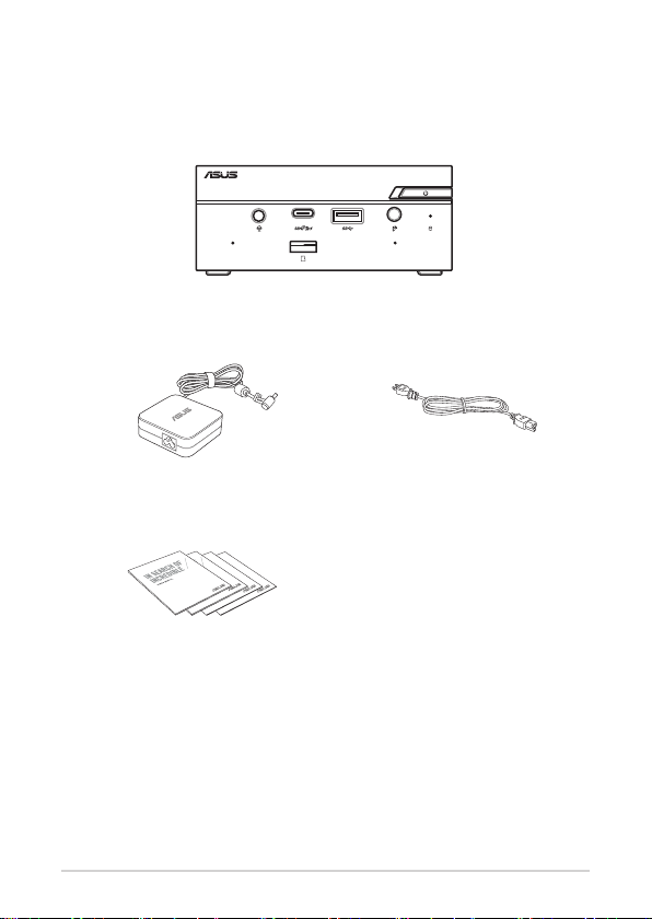
Package contents
Your Mini PC package contains the following items:
ASUS Mini PC PN Series
AC power adapter* Power cord*
Technical documentations
PN Series
7

NOTE:
• *The bundled power adapter may vary by model and territories.
• Some bundled accessories may vary with dierent models.
For details on these accessories, refer to their respective user
manuals.
• The device illustration is for reference only. Actual product
specications may vary with models.
• If the device or its components fail or malfunction during
normal and proper use within the warranty period, bring the
warranty card to the ASUS Service Center for replacement of
the defective components.
8
PN Series

1
Getting to know your Mini PC
Features
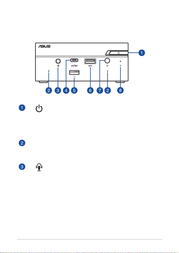
Front view
Power button
The power button allows you to turn the Mini PC on or o.
You can use the power button to put your Mini PC to sleep
mode or press it for four (4) seconds to force shutdown
your Mini PC.
Microphone
The built-in microphone can be used for video
conferencing, voice narrations, or simple audio recording.
Headphone/Headset/Microphone jack
This port allows you to connect amplied speakers or
headphones. You can also use this port to connect your
headset or an external microphone.
10
PN Series
USB 3.2 Gen 2 Type-C®/DisplayPort combo port
This USB Type-C® (Universal Serial Bus) port provides a
transfer rate of up to 10 Gbit/s, and supports Display port
1.4. Use a USB Type-C® adapter to connect your Mini PC
to an external display. This port also supports the Battery
Charging 1.2 technology that allows you to charge your
USB devices.
NOTE:
• Battery Charging 1.2 technology is only
available on selected models, and provides a
maximum of 5V / 1.5A output.
• When using only this port as a display output
source, this port will support a resolution
of up to 7680 x 4320 @30Hz, or 5120 x 2280
@120Hz. The resolution may also be aected
by the cabling and output device.
Memory card slot
The built-in memory card reader enables your Mini PC to
read and write data to and from Micro SD cards.
USB 3.2 Gen 1 port
The USB 3.2 Gen 1 (Universal Serial Bus) port provides a
transfer rate up to 5 Gbit/s.
IR receiver
The remote sensor detects signal from your remote
control, allowing you to access the control panel from a
distance.
NOTE: The remote control is purchased separately
Drive activity indicator
This indicator lights up when your Mini PC is accessing the
internal storage drive.
PN Series
11
Left view
Air vents (intake vent)
The air vents allow cooler air to enter your Mini PC chassis.
IMPORTANT: For an optimum heat dissipation and
air ventilation, ensure that the air vents are free
from obstructions.
12
PN Series
Right view
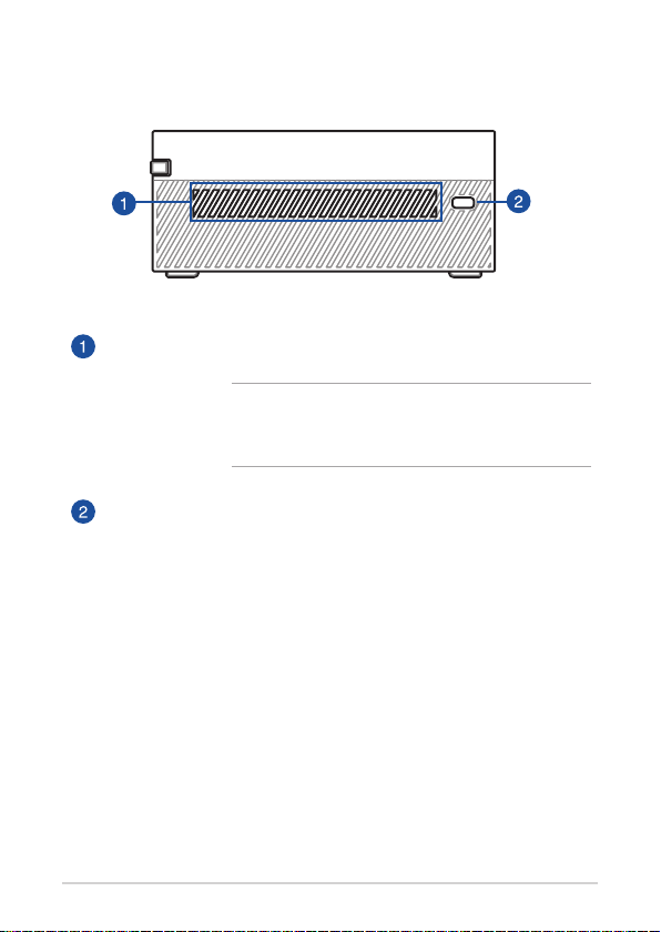
Air vents (intake vent)
The air vents allow cooler air to enter your Mini PC chassis.
IMPORTANT: For an optimum heat dissipation and
air ventilation, ensure that the air vents are free
from obstructions.
Kensington security slot
The Kensington security slot allows you to secure your
Mini PC using Kensington® security products.
PN Series
13
Rear view
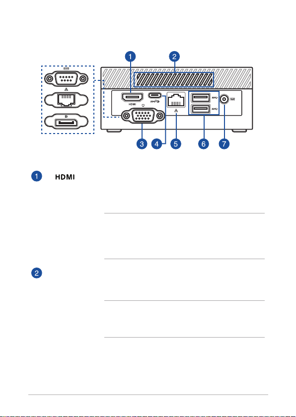
HDMI™ port
The HDMI™ (High Denition Multimedia Interface) port
supports a Full-HD device such as an LCD TV or monitor to
allow viewing on a larger external display.
NOTE: When using only this port as a display
output source, this port will support a resolution of
up to 3840 x 2160 @60Hz. The resolution may also
be aected by the cabling and output device.
Air vents (exhaust vent)
The air vents allow your Mini PC chassis to expel hot air
out.
IMPORTANT: For an optimum heat dissipation and
air ventilation, ensure that the air vents are free
from obstructions.
14
PN Series
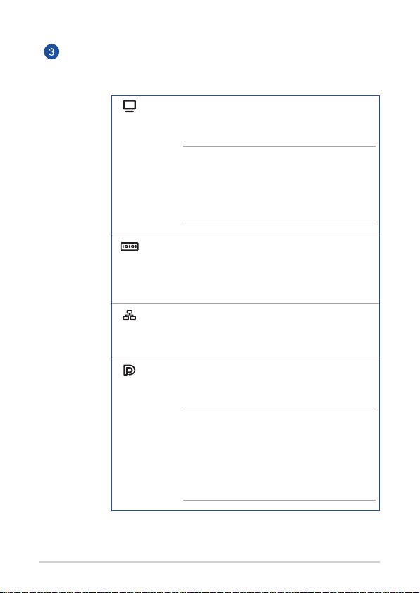
Congurable port
This port varies between models and consists of the
following port options:
VGA port
This port allows you to connect your Mini PC to an
external display.
NOTE: When using only this port as
a display output source, this port will
support a resolution of up to 1920 x 1200
@60Hz. The resolution may also be aected
by the cabling and output device.
Serial (COM) connector
The 9-pin serial (COM) connector allows you to
connect devices that have serial ports such as
mouse, modem, or printers.
LAN port
The 8-pin RJ-45 LAN port supports a standard
Ethernet cable for connection to a local network.
DisplayPort
This port allows you to connect your Mini PC to an
external display.
NOTE: When using only this port as
a display output source, this port will
support a resolution of up to 7680 x 4320
@30Hz, or 5120 x 2280 @120Hz. The
resolution may also be aected by the
cabling and output device.
PN Series
15
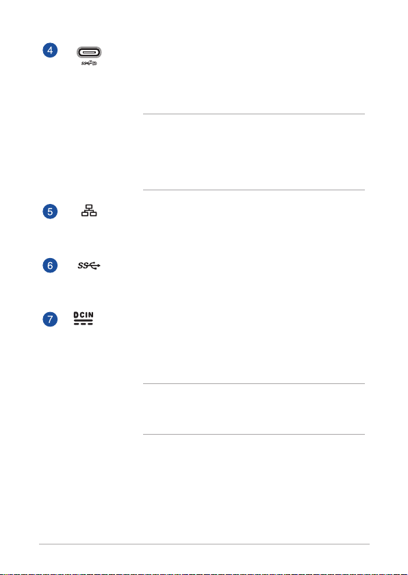
USB 3.2 Gen 2 Type-C®/DisplayPort combo port
This USB Type-C® (Universal Serial Bus) port provides a
transfer rate of up to 10 Gbit/s, and supports Display port
1.4. Use a USB Type-C® adapter to connect your Mini PC to
an external display.
NOTE: When using only this port as a display
output source, this port will support a resolution of
up to 7680 x 4320 @30Hz, or 5120 x 2280 @120Hz.
The resolution may also be aected by the cabling
and output device.
LAN port
The 8-pin RJ-45 LAN port supports a standard Ethernet
cable for connection to a local network.
USB 3.2 Gen 1 port
The USB 3.2 Gen 1 (Universal Serial Bus) port provides a
transfer rate up to 5 Gbit/s.
Power input
The supplied power adapter converts AC power to DC
power for use with this jack. Power supplied through this
jack supplies power to the Mini PC. To prevent damage to
the Mini PC, always use the supplied power adapter.
WARNING! The power adapter may become warm
to hot when in use. Do not cover the adapter and
keep it away from your body.
16
PN Series

Using your Mini PC
2
Getting started
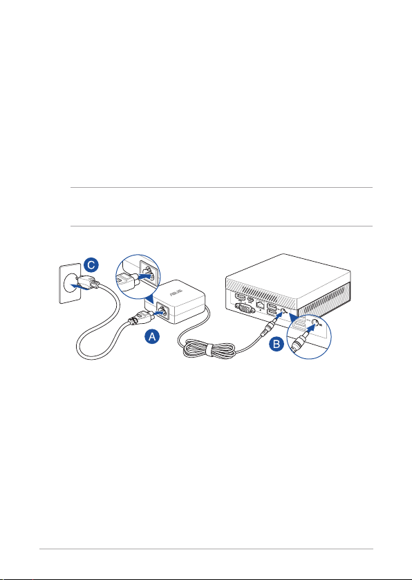
Connect the AC power adapter to your Mini PC
To connect the AC power adapter to your Mini PC:
A. Connect the power cord to the AC power adapter.
B. Connect the DC power connector into your Mini PC’s power (DC)
input.
C. Plug the AC power adapter into a 100V~240V power source.
NOTE: The power adapter may vary in appearance, depending on
models and your region.
18
PN Series

IMPORTANT!
• We strongly recommend that you use only the AC power
adapter and cable that came with your Mini PC.
• We strongly recommend that you use a grounded wall socket
while using your Mini PC.
• The socket outlet must be easily accessible and near your Mini
PC.
• To disconnect your Mini PC from its main power supply, unplug
your Mini PC from the power socket.
NOTE:
The power adapter may vary between models and territories, please
refer to the following for more information on the dierent adapters:
65W Power adapter
• Input voltage: 100-240 Vac
• Input frequency: 50-60 Hz
• Rating output current: 3.42 A / 3.33 A (65.0 W)
• Rating output voltage: 19.0 V / 19.5 V
90W Power adapter
• Input voltage: 100-240 Vac
• Input frequency: 50-60 Hz
• Rating output current: 4.74A / 4.62 A (90.0 W)
• Rating output voltage: 19.0V / 19.5 V
PN Series
19

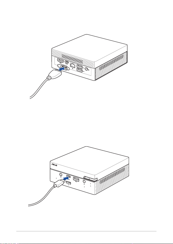
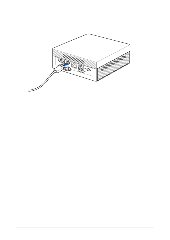
Connect a display panel to your device
You can connect a display panel or projector to your device that has the
following connectors:
• VGA connector
• DisplayPort
• HDMI™ connector
• USB Type-C®/DisplayPort connector
NOTE: These ports may vary per model.
To connect a display panel to your Mini PC:
Connect one end of a VGA, DisplayPort, HDMI™ or USB Type-C® cable to an
external display, and the other end of the cable to your Mini PC’s VGA port,
DisplayPort, HDMI™ port, or one of the USB 3.2 Gen 2 Type-C®/DisplayPort
combo ports.
20
PN Series

NOTE:
• Up to four display panels may be connected simultaneously
when using both front and rear USB 3.2 Gen 2 Type-C
®
/
DisplayPort combo ports, HDMI™ port, and congurable port*.
• Using a one of the ports listed below as the only display output
source will provide the following maximum resolution**:
- Front USB 3.2 Gen 2 Type-C®/DisplayPort combo port
Supports a resolution of up to 7680 x 4320 @30Hz, or 5120 x
2280 @120Hz.
- Rear USB 3.2 Gen 2 Type-C®/DisplayPort combo port
Supports a resolution of up to 7680 x 4320 @30Hz, or 5120 x
2280 @120Hz.
- HDMI™ port
Supports a resolution of up to 3840 x 2160 @60Hz.
- Congurable VGA por t
Supports a resolution of up to 1920 x 1200 @60Hz.
- Congurable DisplayPort port
Supports a resolution of up to 7680 x 4320 @30Hz, or 5120 x
2280 @120Hz.
* This port may vary per model. Please refer to the Features section for the location of the ports.
** The maximum resolution may be aected by the cabling and output device.
PN Series
21
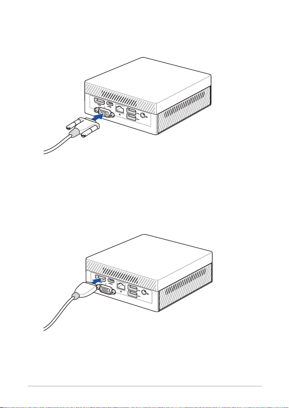
Connect display via VGA port
Connect display via HDMI™ port
22
PN Series
Connect display via DisplayPort
Connect display via front USB 3.2 Gen 2 Type-C®/DisplayPort combo port
PN Series
23
Connect display via rear USB 3.2 Gen 2 Type-C®/DisplayPort combo port
24
PN Series
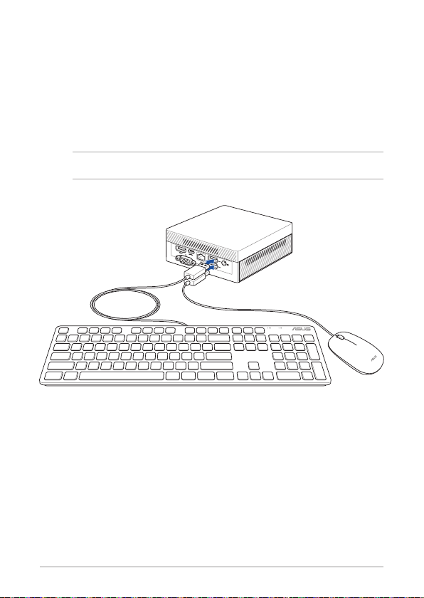
Connect the USB cable from keyboard or mouse
You can connect generally any USB keyboard and mouse to your Mini PC.
You can also connect a USB dongle for a wireless keyboard and mouse set.
To connect a keyboard and mouse to your Mini PC:
Connect the USB cable from your keyboard and mouse to any of the USB
ports of your Mini PC.
NOTE: The keyboard varies with country or region.
PN Series
25
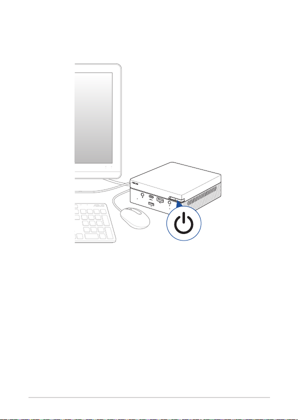
Turn on your Mini PC
Press the power button to turn on your Mini PC.
26
PN Series

Turning your Mini PC o
If your Mini PC is unresponsive, press and hold the power button for at least
four (4) seconds until your Mini PC turns o.
Putting your Mini PC to sleep
To set your Mini PC to enter Sleep mode by pressing the Power button
once, search for Control Panel in the Windows Search Box, then navigate to
Hardware and Sound > Power Options > Choose what the power button
does, and set When I press the power button to Sleep.
Entering the BIOS Setup
BIOS (Basic Input and Output System) stores system hardware settings that
are needed for system startup in the Mini PC.
In normal circumstances, the default BIOS settings apply to most conditions
to ensure optimal performance. Do not change the default BIOS settings
except in the following circumstances:
• An error message appears on the screen during the system bootup and
requests you to run the BIOS Setup.
• You have installed a new system component that requires further BIOS
settings or update.
WARNING! Inappropriate BIOS settings may result to instability
or boot failure. We strongly recommend that you change the BIOS
settings only with the help of a trained service personnel.
PN Series
27

Load default BIOS settings
To load the default values for each of the parameters in your BIOS:
• Enter the BIOS by pressing <F2> or <DEL> on the POST screen.
NOTE: POST (Power-On Self Test) is a series of software controlled
diagnostic tests that run when you turn on your Mini PC.
• Navigate to the Exit menu.
• Select the Load Optimized Defaults option, or you may press <F5>.
• Select OK to load the default BIOS values.
28
PN Series
 Loading...